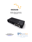
1
9 5 2 2 A L- Ba nd Tr a ns cei ver P r o d uc t I nf or m a t i o n G ui de Revision 1.01 Iridium Satellite LLC 6701 Democracy Blvd., Suite 500 Bethesda, MD 20817 USA www.iridium.com Toll Free: +1.866.947.4348 [US Only] International +1.480.752.5155 email: [email protected] Unit 11 – 33 Riley Road – Woodmead + 27 11 612 3660 [email protected] www.gc-sat.com Iridium Satellite LLC 9522A L-Band Transceiver Product Information Guide V1.1 032405 Contents Revision History............................................................................................................................................ 2 1.0 Product Overview ............................................................................................................................ 3 2.0 Standards Compliance .................................................................................................................... 3 2.1 FCC Compliance ......................................................................................................................... 3 2.2 CE Compliance ........................................................................................................................... 3 3.0 Physical Specifications .................................................................................................................... 4 3.1 Environmental ............................................................................................................................. 4 3.2 Dimensions.................................................................................................................................. 4 3.3 Interface Connectors ................................................................................................................... 6 3.3.1 Multi-Interface Connector ................................................................................................... 6 3.3.2 Antenna Connector............................................................................................................. 7 3.3.3 SIM Chip Reader ................................................................................................................ 7 3.4 Mounting...................................................................................................................................... 7 3.5 Connector Sealing in Harsh Environments ................................................................................. 7 4.0 Electrical Interfaces ......................................................................................................................... 8 4.1 DC Power Interface ..................................................................................................................... 8 4.1.1 DC Power Interface Signal Descriptions ............................................................................ 8 4.1.2 DC Power Input Specifications ........................................................................................... 8 4.2 Control/Digital Audio (DPL bus) Interface ................................................................................... 8 4.2.1 Control/Digital Audio Interface Signal Descriptions............................................................ 8 4.3 RS232 Data Interface.................................................................................................................. 9 4.3.1 RS232 Data Signal Descriptions ........................................................................................ 9 4.3.2 Autobaud ............................................................................................................................ 9 4.4 Analog Audio Interface ................................................................................................................ 9 4.4.1 Analog Audio Interface Signal Descriptions ....................................................................... 9 4.5 SIM Interface ............................................................................................................................... 9 4.6 RF Interface............................................................................................................................... 10 4.6.1 R F Inte r f ac e S p ec if ic a ti o ns ..................................................................................... 10 4.6.2 R a d i o C ha r ac ter is t ic s ................................................................................................ 10 5.0 Ins tr uc tions f or t h e s a f e Ins tallation a n d u s e of t h e 9 5 2 2 A L B T ................................. 11 5.1 Ins tr uc tions f or t h e Integrator.............................................................................................. 11 5.2 Instructions from the integrator to the user ............................................................................... 11 6.0 Modem Commands and Configuration.......................................................................................... 11 Revision History Revision V1.0 V1.01 Date 02 14 2005 03 24 2005 Comment First revision Revised upper range of operating temperature specification in Section 3.1 Export Compliance Information This product is controlled by the export laws and regulations of the United States of America. The U.S. Government may restrict the export or re-export of this product to certain individuals and/or destinations. For further information, contact the U.S. Department of Commerce, Bureau of Industry and Security or visit www.bis.doc.gov. 2 Iridium Satellite LLC 9522A L-Band Transceiver Product Information Guide V1.1 032405 1.0 Product Overview The 9522A L-Band Transceiver (LBT) is designed to be integrated into a specific application with other hardware and software to produce a solution designed for a specific application or vertical market. Some examples of these solutions include a maritime voice telephony terminal or a vehicle tracking solution. TheLBTf unc t i onal l ys uppor t sal lofI r i di um’ sv oi ceanddat as er v i c es. Applications can be built to use one or multiple services using the voice and data interfaces. The 9522A is a functional replacement to the 9522 “ Sebr i ng”LBT.Howev eri ts houl dbenot edt hatt her ear esome differences to the voice interface. The 9522A is regulatory approved for FCC, Canada, and CE assuming an antenna with a gain of ~3 dBi. This allows the LBT to be integrated into a variety of subscriber products, or retrofitted into existing LBTbased products. These products, when integrated together will require regulatory testing to be conducted by the integrator. TheLBTi ses sent i al l ypr ov i dedasa‘ bl ackbox’wi t hal li nt er f aces provided via a DB25 connector. The product provides the core transceiver module and SIM card reader. All other functions and hardware such as keypad, display, power supply, antenna etc. must be provided by the solution developer. The DB25 provides the following interfaces and connections: Analog Audio Control / Digital Audio RS232 Power Input On / Off 2.0 Standards Compliance The 9522A is designed to comply with the standards for Radio Emissions Compliance, Electromagnetic Compatibility, and AC Safety in the United States, European Union and Canada. 2.1 FCC Compliance The 9522A is certified under 47 CFR Part 25 as FCC ID:Q639522A. It also complies with Part 15 of the FCC Regulations. Operation is subject to the condition that this device does not cause harmful interference. Any changes or modifications, including the use of a non-standard antenna, not expressly approved by the party responsible for compliance could void the user's authority to operate the equipment. IMPORTANT: To comply with FCC RF exposure requirements, a minimum separation of 20 cm is required between the antenna and all persons. 2.2 CE Compliance This product, when marked with the CE symbol, complies with the European Community Council Directive for R&TTE, 99/5/EC, provided that the integrator/user adheres to the instructions detailed in this LBT Interface Specification. This product is in compliance with applicable ETSI standards. Compliance with the requirements of ETSI EN 301 489 requires the use of a shielded digital data interface cable. 3 Iridium Satellite LLC 9522A L-Band Transceiver Product Information Guide V1.1 032405 3.0 Physical Specifications The 9522A is depicted in Figure 1 below. Figure 1: Top View of 9522A 3.1 Environmental The environmental specifications of the 9522A LBT are summarized in Table 1 below. Table 1: Environmental Specifications Parameter Operating Temperature Range Operating Humidity Range Storage Temperature Range Storage Humidity Range Value -20ºC to + 60ºC ≤75% RH -40ºC to + 85ºC ≤93% RH 3.2 Dimensions The overall dimensions of the 9522A LBT and its weight are summarized in Table 2 below. Dimensioned views of the 9522A LBT are shown in Figures 2-5 which follow. Table 2: Mechanical Dimensions Parameter Length (including antenna connector) Length (excluding antenna connector) Width Depth Weight (approximate) Value 216.1 mm ( 8. 51” ) 196.4 mm ( 7. 73” ) 82.6 mm ( 3. 25” ) 39.0 mm ( 1. 54” ) 659 g Figure 2: Side View 4 Iridium Satellite LLC 9522A L-Band Transceiver Product Information Guide V1.1 032405 Figure 3: Bottom View Figure 4: Antenna Connector End View Figure 5: Multi-Interface Connector End View 5 Iridium Satellite LLC 9522A L-Band Transceiver Product Information Guide V1.1 032405 3.3 Interface Connectors The 9522A LBT incorporates three interface connectors: Multi-Interface Connector (located on the end of the 9522A LBT) Antenna Connector (located on the end of the 9522A LBT; opposite to the multi-interface connector) Subscriber Identity Module (SIM) Chip Connector (located beneath a cover plate atop the 9522A LBT) 3.3.1 Multi-Interface Connector The multi-interface connector is a 25 pin D-subminiature type that includes four interfaces: DC Power Control/Digital Audio (DPL bus) RS232 Data Analog Audio The pin out information for this connector is given in Table 3 below. Table 3: 25-way connector pin-out Contact 1 2 3 4 5 6 7 8 9 10 11 12 13 14 15 16 17 18 19 20 21 22 23 24 25 Signal EXT_ON_OFF EXT_11HZ EXT_GND EXT_PWR SPKR_AUD DA_TX DF_RI DF_RTS DF_S_TX DF_DCD DA_FS DA_CLK DF_S_RX 0V MIC_AUD EXT_PWR EXT_GND DPL_TX DF_DTR DPL_RX DF_DSR DF_CTS 0V DA_RX 0V Description External connection for On / Off key input to Daytona LBT 90ms“ f r amesy nc”si gnal ( usedi nt est i ng) Power Ground input to Daytona LBT Power input to Daytona LBT Speaker audio output from Daytona LBT PCM digital audio output from Daytona LBT Data / Fax Ring Indication output from Daytona LBT Data / Fax Request to Send input to Daytona LBT Data / Fax (UART) data input to Daytona LBT Data / Fax Data Carrier Detect output from Daytona LBT PCM digital audio frame sync output from Daytona LBT PCM digital 2.048MHz audio clock output from Daytona LBT Data / Fax data (UART) output from Daytona LBT Signal ground, 0V signal reference and return Microphone audio input to Daytona LBT Power input to Daytona LBT Power Ground input to Daytona LBT Digital Peripheral Link (UART) data output from Daytona LBT Data / Fax Data Terminal Ready input to Daytona LBT Digital Peripheral Link (UART) data input to Daytona LBT Data / Fax Data Set Ready output from Daytona LBT Data / Fax Clear to Send output from Daytona LBT Signal ground, 0V signal reference and return PCM digital audio input to Daytona LBT Signal ground, 0V signal reference and return 6 Iridium Satellite LLC 9522A L-Band Transceiver Product Information Guide V1.1 032405 3.3.2 Antenna Connector The 9522A LBT provides a single 50 Ω, TNC type antenna connector both transmit and receive. 3.3.3 SIM Chip Reader An integrated SIM chip reader is provided on the 9522A LBT. This connector allows installation of the chip form of the SIM beneath a cover plate on the 9522A LBT housing. 3.4 Mounting The 9522A LBT incorporates (6) mounting holes on its bottom surface that can aid in its mounting. See Figure 3 for locations of these features. It is recommended that a thread-forming screw be used to mount the 9522A LBT via these features. Particularly, a Textron Camcar® Taptite® II Thread-Rolling Fastener of M3.5x0.6 thread type is recommended. This fastener has a 15IP Torx Plus® pan head and is available in lengths of 6, 8, 12, 16, and 20 mm as part number 3BE-P802-00, 3BE-P803-00, 3BE-P8185-00, 3BEP804-00, 3BEP8186-00, and 3BE-P8187-00 respectively. Length should be chosen to ensure that penetration into the 9522A LBT housing does not exceed 11 mm. If a 6-32 thread type is desired, a Textron Camcar® Taptite® II Thread-Rolling Fastener with a 15IP Torx Plus® pan head is available in lengths of 1/4, 5/16, 3/8, 1/2, 5/8, 3/4, and 1 inch as part number 3BE-P814-00, 3BE-P8123-00, 3BEP815-00, 3BE-P816-00, 3BE-P8124-00, 3BE-P817-00, and 3BE-P818-00 respectively. A 10IP Torx Plus® flat head version is also available in a single length of 1/2 inch as part number 3BE-P801-00. Another 6-32 thread type option is to insert a helical coil insert with a 6-32 internal thread into these features thus accommodating 6-32 threaded fasteners as mounting hardware for the 9522A LBT. National Aerospace Standard NASM122238 serves as a technical reference for the recommended helical coil insert. 3.5 Connector Sealing in Harsh Environments If the 9522A LBT is to be used in a harsh environment with exposure to high humidity or water, the mating of the multi-interface connector must be further sealed to protect from moisture entry. It is recommended t hatabeadofRTVsi l i coneseal antbepl acedont heconnect ormat i ngt ot he9522ALBT’ smul t i -interface connector where shown in Figure 6 below. A material similar to Permatex 16B should be used. Figure 6: Placement of Silicone RTV bead around t heconnect ormat i ngt ot he9522A’ smul t i -interface connector. 7 Iridium Satellite LLC 9522A L-Band Transceiver Product Information Guide V1.1 032405 4.0 Electrical Interfaces The subsections to follow contain interface information for the electrical interfaces of the 9522A LBT. 4.1 DC Power Interface 4.1.1 DC Power Interface Signal Descriptions The DC power interface is comprised of the DC power inputs and a control signal as summarized in Table 4 below. The EXT_PWR and GND inputs are used to supply DC power to the 9522A LBT. The EXT_ON_OFF control input is pulled to a GND level to toggle the 9522A LBT on and off. Note that both pairs of pins should be connected for EXT PWR and EXT GND. Table 4: Control/Audio Interface Signal Descriptions Signal Name EXT_PWR (pin 4 and 16) EXT_GND (pin 3 and 17) EXT_ON_OFF (pin 1) Signal Description External power +4.4VDC input External power GND input Power on/off control input 4.1.2 DC Power Input Specifications The DC power requirements for the 9522A LBT are summarized in Table 5 below. Note that these requirements apply to DC power measured at the 9522A LBT multi-interface connector input. Table 5: DC Power Input Specifications Parameter Main Input Voltage Range Main Input Voltage - Nominal Main Input Voltage –Ripple Value +4.0 VDC to +4.8 VDC 4.4VDC 40 mV peak to peak Consumption at +4.4 VDC Input Standby Power (average) Peak Transient Current –Transmit Current Average –Continuous Transmit at Maximum RF Power (see note) Power Average –Voice/Data Call (see note) Value 570mW 2.5A 1.0A 2200mW Note: The average power consumption depends on the view of the satellite constellation from the antenna. 4.2 Control/Digital Audio (DPL bus) Interface 4.2.1 Control/Digital Audio Interface Signal Descriptions The control/digital audio interface enables peripherals such as handsets and SIM card readers to be interfaced to the 9522A LBT. The interface utilizes an Iridium Proprietary communication bus not detailed in this fact sheet. Details can be made available after appropriate Non-Disclosure and/or License Agreements are executed. 8 Iridium Satellite LLC 9522A L-Band Transceiver Product Information Guide V1.1 032405 4.3 RS232 Data Interface 4.3.1 RS232 Data Signal Descriptions The RS232 data interface is comprised of eight standard RS232 data, control, and status signals plus a ground level signal reference. This interface allows a connected Data Terminal Equipment (DTE) to utilize t he9522A LBT’ smodem f unct i onal i t yvi aATcommandcont r ol .A 3-wire RS232 Data minimal interface may also be implemented however the 9 wire interface offers better control and is the recommended implementation. 4.3.2 Autobaud Autobaud is enabled by default. Aut obaudwi l loccuront hef ol l owi ngchar act er s‘ a’ ,‘ A’ ,or CR (carriage return). Autobaud will also occur on the escape sequence character, provided this is an odd number c har ac t er .Nor mal l yt hi si ssett o‘ +’ i nr egister S2. See the AT Command Reference for details. 4.4 Analog Audio Interface 4.4.1 Analog Audio Interface Signal Descriptions The analog audio interface is comprised of the analog audio input and output signals referenced to the 0V signal ground as summarized in Table 6 below. Table 6: Analog Audio Interface Signal Descriptions Signal Name MIC_AUD (pin 15) SPKR_AUD (pin 5) 0V (pins 14, 23 and 25) Signal Description Analog audio input to LBT Analog audio output from LBT Signal ground 4.5 SIM Interface An integrated SIM chip reader is provided on the 9522A LBT. An external SIM card reader may also be interfaced as a peripheral to the 9522A LBT via the DPL bus (control/audio interface). A SIM card in the external reader will take precedence over the SIM chip in the integrated connector when both are present. 9 Iridium Satellite LLC 9522A L-Band Transceiver Product Information Guide V1.1 032405 4.6 RF Interface 4.6.1 R F Interface Specifications The RF interface requirements for the 9522A LBT are summarized in Table 7 below. Table 7: General RF Parameters Parameter Value Frequency Range 1616 MHz to 1626.5 MHz Duplexing Method TDD (Time Domain Duplex) Oscillator Stability ± 1.5 ppm Input/Output Impedance 50Ω Multiplexing Method TDMA/FDMA 4.6.2 Radio Characteristics The tables within this section contain radio characteristics of the 9522A LBT. Table 8: In-Band Characteristics Parameter Average Power during a transmit slot (max) Average Power during a frame (typical) Receiver Sensitivity at 50W (typical) Receiver Spurious Rejection at offsets > 1 MHz (typical) Value 7W 0.6 W -118.5 dBm 60 dB Table 9: Link Margin Configuration 9522A LBT with accessory antennas (Note 1) Cable Loss 2 dB (Note 2) Link Margin 13.1 dB (Note 3) Note 1: Other antenna options are available Note 2: Cable losses should be minimized Note 3: Link Margin given for free space 10 Iridium Satellite LLC 9522A L-Band Transceiver Product Information Guide V1.1 032405 5.0 Instructions for the safe Installation and use of the 9522A LBT The 9522A LBT is intended for integration into a finished product. The integrator of the 9522A LBT is required to connect a power supply, antenna, and user interface to the 9522A LBT. To ensure that the 9522A LBT is correctly installed the following general instructions (sub-section 5.1) are provided for the installer. The integrator will be required to supply the end user of the integrated product, incorporating the 9522A LBT, with operating instructions and any other information relating to the maintenance and safety of the equipment (sub-section 5.2). 5.1 Instructions for the Integrator The 9522A LBT must be installed by an appropriately qualified installer and mounted securely as described in section 3.4 of this document. The power supply used to power the 9522A LBT must be checked to ensure it meets the requirements of sub-section 4.1.2 of this document. Electrical connections to the 9522A LBT multi-interface connector shall be as designated in Table 3 of sub-section 3.3.1 of this document. The current and voltage rating of the multi-interface connector cable shall meet the requirements of the LBT DC power input. The electrical characteristics of the multi-interface connector cable shall not degrade the 9522A LBT digital communications and analog audio signals. The multi-interface connector cable will provide adequate screening from external electromagnetic interference. The 9522A LBT shall not be located in close proximity to sources of extreme temperature which will cause it to be operated outside of its temperature specification. The 9522A LBT shall not be operated without an appropriate antenna connected to its Antenna connector via a suitable 50 Ohm coaxial cable. This antenna shall be sited at least 20cm away from any person. 5.2 Instructions from the integrator to the user To comply with the requirements of sub-clause 1.7.2 (Safety instructions) of the European Information technology equipment safety standard EN60950-1:2002 the integrator must ensure that: ‘ Suf f i ci enti nf or mat i ons hal lbepr ov i dedt ot heUSER c onc er ni ngany condition necessary to ensure that, when used as prescribed by the manufacturer, the equipment is unlikely to present a hazard within the meaning of this standard. If it is necessary to take special precautions to avoid the introduction of hazards when operating, installing, servicing, transporting or storing equipment, the necessary instructions shall be madeav ai l abl e. ’ As part of these instructions the installer should inform the user that they should not service the 9522A LBT. 6.0 Modem Commands and Configuration The 9522A is configured through the use of AT commands. A full listing of the supported AT commands can be found in the AT Command Reference document. 11