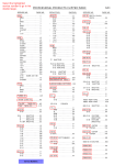
1
Sunny Island 5048U
Product Training
Agenda
n What is Sunny Island ?
n Configuration options
n Hardware and Wiring
n Battery & BMS
n Generators & GMS
n System Management
n MMC/SD card
n Communication
2
What is Sunny Island 5048U
What is Sunny Island 5048 ?
n A modular, bi-directional, battery based
inverter designed for off-grid and backup
power applications
n A utility-interactive grid-tied inverter for
use with 48 Vdc sources
n A hybrid system controller for systems
with multiple energy sources
o Battery charge control
o Generator management
o System management
n A data logger and
communications device
o Optimize system performance
o Troubleshooting
o Remotely monitor, program
and control system
4
Overview - Off-Grid Power System
n Typically in remote areas
n Stand-alone power supply
n Multiple energy sources are
typically present
n Flexible system architecture
adapts to local supplies and
conditions
5
Overview - Backup Power System
n Grid-feeding when grid is
operating normally
n Power supply during short
or long term grid failures
n Transparent “near UPS”
switching times (16 ms)
n Charge and maintain battery
when grid returns
6
Sunny Island – Basic Tasks
n Grid monitoring
n Grid forming
o
o
Supply and control of frequency
Supply and control of voltage
n Supply of power
o
o
Supply of active power
Supply of reactive power
n Transfer and conversion of energy
o
o
Conversion from AC into DC for battery charging
Conversion from DC into AC for supply of energy
n Control of external loads and energy sources
o
Load control
o
Generator start /stop
7
Sunny Island Family
8
Sunny Island Development History
Sunny Island
4248/4248U
Sunny Islands
5048 / 5048U
Sunny Island
4500
2001
CHP applications,
Special applications
ROW Only
2004
Small systems, Single
device applications
US and ROW Versions
2007
Multicluster systems,
High Power, variety of
functions
US and ROW Versions
9
Sunny Island Products – Overview
Properties
SI4500
SI4248U
SI5048U
Parallel operation
ü
ü
3-phase operation
ü
ü
Grid and generator
support
ü
ü
DC-coupling
possible
Extended battery,
load and generator
management
Quick Configuration
Guide
Data logging and
Programming with
MMC/SD Card
ü
ü
ü
ü
ü
ü
ü
10
SI 5048U – Technical Data
Nominal AC power (25°C)
5.0 kW Continuous
Nominal AC voltage
120 V
Nominal frequency
60 Hz
6.5 kW30min / 8.4 kW1min
Maximum AC Output current 120 Amps
Nominal DC voltage
48 V
Maximum efficiency
>95%
Integrated Isolation Relay
56 Amps Continuous
Losses Idle/Standby
25W/4W
Maximum System Size
1~/2~/3~
Other Features
SD/MMC Card, Single Point of Operation
AC Coupling/DC Coupling/Both
112 Amps (26.9 kW) with
stacked Sunny Islands
20 kW/20 kW/ 15 kW
11
Efficiency optimized for off grid systems
n High efficiency in both invert and charge modes
o
o
o
Max. Efficiency > 95 %
Optimized for low load operation (η > 90 % from P= 5 - 100%)
Power dependant “sleep mode” for parallel slave units
1,00
0,90
0,80
Efficiency
0,70
0,60
0,50
ETA
0,40
0,30
0,20
0,10
0,00
0
1000
2000
3000
4000
5000
AC-Power [W]
12
Sunny Island 5048U
Hardware and Connections
Front Panel - Easy To Use
n Single Point of Operation
o
o
Master unit is the only user interface
- Settings, observe values, initiate switching & timers
Master unit monitors and controls Slave units
- Software updates at Master, Master updates the Slaves
n Integrated MMC Card
o
o
o
o
Logging of all data and parameters
(last 100 Days)
Logging of all event, warning, and
failure messages (last100 Days)
Software-Update via MMC Card
Logging of all settings and
parameters on MMC Card
14
Sunny Island Enclosure
n Corrosion resistant painted die cast aluminum
n Incorporates SMA‘s patented Opticool system
o
o
o
No air blowing on sensitive electronics
Large ambient temperature range (-25 to +50°C)
Maintains output power at high temperatures (4 kW at 45°C)
Warm
exhaust air
Cold air
intake
15
Sunny Island 5048 – Interior View
Inverter bridge
board
Display and
Keypad
SD/MMC Card
DC Breaker
Control board
DC Connections
AC Connections
Communication
area
Programmable
Relays
16
Sunny Island 5048 – Knockouts
(2) ¾” knock outs for
AC connections
(1) 1.5” knock out
for DC
(2) ¾” knockouts for
communications
17
1 ½ ” knock out for DC Conductors
PE
+
Two 1/0 positive
-
Two 1/0 Negative
Equipment Ground #4 AWG
18
Sunny Island 5048 – Wiring
* DC Equip. Ground– 1/0
DC Pos./Neg. – Dual 1/0
Communication
Cables
RJ-45 “Ethernet”
CAN Buss for
Inverter control
AC1 L/N
AWG 6/4
AC2 L/N
AWG 6/4
AC Equip. Ground
AWG 6/4
Control Relays
AWG 24 typical
* Suggestion: Ground DC negative at battery terminal
19
Connections to Sunny Island 5048
20
Sunny Island 5048U
AC and DC Coupling
What is “Coupling“?
Supply bus
n Supply line from the source to the load forms a “bus“
Charge
controller
DC bus
n DC coupling: Connection of sources and loads via a DC bus
22
AC Coupling
AC bus
n AC coupling: Connection of sources and loads via an AC bus
23
Advantages of AC Coupling: Planning
n Simple design
o
o
Manageable
Modular
n Special knowledge is not required
o
o
Standard energy sources
Standard installation technologies can be used
n Little efforts
o
o
Low planning costs
Little planning time
24
Advantages of AC Coupling: Flexibility
AC bus
Up to miles
n Large selection of loads, energy sources, and system components
n Great distances between components are possible
n Simple expansion even after some years
25
Advantages of AC Coupling: Components
n Independent selection of components
o
o
o
Free choice due to grid compatibility
Free choice due to variety of AC sources
Free choice due to variety of AC loads
n Low costs of components due to
o
o
strong market competition
availability almost worldwide
26
Advantages of AC Coupling: Expandable
n Adding Sunny Islands
o
o
o
without changing other components
without reconfiguring the wiring
independent of distances
n Extension of phase number
o
o
from 1-phase to 3-phase
from 1-phase to split phase
n Increase of source power without additional costs
n Addition of loads without additional costs
27
Efficiency with AC coupling (92% Inverter)
Lead acid battery:
η = 80 .. 85 .. 90 %
NiCd-Battery:
η = 55 .. 60 .. 65 %
LiIon-Battery:
η = 90 .. 92 .. 95 %
PV Usage:
η = 95 %
Sunny Island
Assumption: 40 % of energy is
consumed directly!
direct consumption:
η = 92 .. 95 .. 98 %
Sunny Boy
120/240V/60Hz
Discharging:
η = 92 %
Charging:
η = 90 .. 92 .. 95 %
Direct Consumption = E x 40 % x 95 % =
38 % E
Via Battery = E x 60 % x 95 % x 92 % x 85 % x 92 % = 41 % E
} ∑ 79 %
28
Efficiency of MPP DC coupling (92% inverter)
Lead acid battery:
η = 80 .. 85 .. 90 %
Assumption: 40 % of energy
is consumed directly!
MPP Charge controller
Charge Controller:
95 ..97..99 %
Sunny Island
120/240V/60Hz
Inverter
Inverter:
88.. 92..94 %
Direct consumption = E x 40 % x 97 % x 92 % =
36 % E
Over Battery = E x 60 % x 97 % x 85 % x 92 % =
45 % E
} ∑ 81 %
29
Efficiency with MPP DC coupling (92% inverter)
95%
90%
Sy ste m e fficie ncy
85%
80%
75%
AC co up ling SI5 0 4 8
70%
DC co up ling SI5 0 4 8
65%
60%
55%
50%
10%
20%
30%
40%
50%
60%
70%
80%
90%
D ire ct co nsum p t io n
30
Efficiency with MPP DC coupling (90% Inverter)
Lead acid battery:
η = 80 .. 85 .. 90 %
Assumption: 40 % of energy
is consumed directly!
MPP Charge Controller
Charge Controller:
95 ..97..99 %
Inverter
230V/50Hz
Inv:
85.. 90..94 %
Direct consumption = E x 40 % x 97 % x 90 % =
35 % E
Over battery = E x 60 % x 97 % x 85 % x 90 % =
44 % E
} ∑ 79 %
31
Efficiency with MPP DC coupling (90% inverter)
95%
90%
Sy stem efficiency
85%
80%
75%
A C co up ling
70%
DC co up ling
65%
60%
55%
50%
10%
20%
30%
40%
50%
60%
70%
80%
90%
D ir e ct co nsum p t io n
32
Efficiency with PWM DC coupling
Lead acid battery:
η = 80 .. 85 .. 90 %
Approach: 40 % are
consumed directly!
PWM Charger
Inverter
Charge Controller:
99 %
“MPP Factor:”
Factor”:
70..80..90%
120/240V/50Hz
Inv:
85.. 90..94 %
Direct consumption = E x 40 %x 99 % x 80% x 90 % =
Over battery = E x 60 %
29 % E
∑ 65 %
}
x 99 % x 80% x 85 % x 90 % = 36 % E
33
Efficiency with PWM DC coupling
95%
90%
Sy ste m e fficie ncy
85%
80%
75%
A C co up ling
70%
DC co up ling
65%
60%
55%
50%
10%
20%
30%
40%
50%
60%
70%
80%
90%
D ire ct co nsum p t o n
34
Overview of AC / DC Coupling
Requirement
AC Coupling
DC Coupling
Installation
++
standard
specific
Distances
+
in the miles range
-in the feet range
Extensibility
++
extendable
0
very limited
Costs
++
standard products, modular
-expensive loads/wiring
Loads to be supplied
++
all
Dc only
Power
++
up to MW
-lower kW range
Black Start Capability
limited – requires load shed
relay function
++
occurs automatically
35
Sunny Island 5048U
System Configuration Options
Single Phase Configuration (120V )
Stand-alone plus
optional 120/240V
autoformer
One Master and one to 4 slaves
37
Dual Split Phase (Single Phase 240)
38
Three Phase
39
Definition – Cluster / Mulit-cluster (SI Collective)
n Cluster = Several Sunny Islands, One Battery, Common Load
n * Multi-cluster = Several Clusters in parallel operation (SI Collective)
* Multi-Cluster configuration NOT available in US Today
40
Planned village power supply (78kW)
41
System Design - Conclusions
n Highest Flexibility
o
o
o
o
o
AC and/or DC coupled systems are possible
Single phase, split phase, and three phase configurations
Interactive operation with generator and/or public grid
For Off-Grid Systems up to 20 kW per cluster in (Single- or Split
phase), 15 kW per cluster in 3 Phase
Larger systems possible in future with multi-cluster box (MCB)
=
=
...
MCB
Multi-ClusterBox
42
Configuring Sunny Island 5048U
Easy Configuration
Quick Start Guide – Several Options
n "Start System" (if you have accidentally accessed the QCG and
only would like to restart the system)
n "New System" (if you would like to start a new system or perform
changes to the system configuration) –
n "New Battery" (if you would like to change the main battery
settings, but retain the system configuration) –
n "Emerg Charge" (if you would like to charge a deeply discharged
battery using an external source
44
New System
n Quick Configuration Guide
o
Only 6 steps for initial startup of the system
1. System Configuration ( See Overview Table )
2. Device Configuration ( Master or Slave# )
a. Slave configuration stops here.
3. Date and Time
4. Battery (type and capacity)
5. Nominal voltage (see below)
6. Maximum generator current and generator interface
n Change of system voltage (DC) in case of failed battery cells
o
o
48V, 46V, 44V, 42V adjustable
Over all, 3 cells can quit working
45
5048U System Management
Sunny Island – System Management
n System Management
o
o
o
o
Control of other Sunny Islands
Connection to additional sources
Regulation and control of energy sources
Programmable relay controls
n Battery Management
Efficient battery charge and discharge
o Sophisticated charge control algorithms prolong service life
o b
n Load Management
o Connection and disconnection of loads
o
– Based on battery SOC, time of day, load level, etc.
o
Overload capability for motor starting
47
System Management Functions
n Power Control of other AC-Energy Sources
o
(Sunny Boy, Windy Boy, Generator)
n Automatic start and stop of generators
o
SOC dependent
o
Load dependent
o
Time dependant
n Load shedding
o
SOC dependent
o
Load dependent
n Load dependent control of other Sunny Islands
o
(Sleep-Mode)
48
Power management - Droop Mode
n Parallel operation of multiple battery inverters with diesel generators
and/or public grid
n Based on P/f - and Q/V-Statics of energy sources (analogous to
conventional public power supplies)
n Statistics are implemented within Sunny Island® battery inverters
VAC
f
f0
V0
∆f
Frequency
Droop
0
∆V
-2%
-6%
Voltage
Droop
Pno
m
P
0
Qno
Q
m
49
Power control of Sunny Boys
n Frequency Shift Power Control
Pac (%)
Fac-Start delta (1Hz)
Fac-delta- (4,5Hz)
100
Fac-Limit delta (2Hz)
50
Fac-delta+ (4,5Hz)
-4
o
o
-3
-2
-1
f0
+1
+2
+3
+4
Fac (Hz)
No additional communication necessary
A rising grid frequency lowers the energy output of the Sunny
Boys
50
Examples for usage of Droop-Mode
3 Sunny
Islands
SI5048
3 Sunny
Islands
SI5048
51
Relay control
n Relay control by Sunny Island 5048
o
o
o
2 integrated relays in each inverter
Functions are selectable for each relay
More than 15 different functions available today
– Other functions can be added as needed by market
o
o
More Sunny islands equals more functions (4x Sunny Island
within a Cluster = 8 Relays)
Relays have common, NO & NC connections
52
Relay control functions SI5048U
n SOC dependent (in %)
o
o
o
At what SOC does the relay close
At what SOC the relay open
What is time of day ?
– 2 independent time periods with programmable SOC limits
n Power dependent (in kW and minutes)
o
o
o
o
At what power does the relay close
How long has the power been above the limit before activated
At what power does the relay open
How long has the power been below the limit before
deactivated
53
Other Relay Control Functions
n Time dependent (Timer based)
o
o
o
o
2 independent timers
Cyclic usage
(every day at 10:00 / every Friday)
Usage of date and time (on 12.04.2009)
Usage of a running time (01:20:45)
n Other functions
o
o
o
o
o
o
o
Close/open while in absorption phase
Close/open when a warning or failure occurs
Close/open while Sunny Island is in operation
Close/open while the generator is in operation
Close/open while the grid is present
Control of battery room fan
Control of battery bubbler (electrolyte circulation pump)
54
System management – System security
n Silent Mode
o
o
o
Operation grid tied as backup system
Battery is fully charged
Loads are completely supplied by grid
n Benefits:
Ø
Ø
Ø
Ø
Ø
Ø
Stops switching operation
Lowers SI internal power consumption (25 Watts >> 4 Watts)
Still transfers loads seamlessly in case of a grid failure
Reduces energy needed to keep batteries charged
Switches to float charge periodically to keep battery at high
SOC
Protects batteries against over charging
55
System management – System security
n Short circuit detection
o
o
o
o
o
Short circuit in Off-Grid system
or in an external source
Current limit is five times the
nominal current
Disconnection of external
sources within 20ms
Carrying of a short circuit
current (120 Amps AC) for
100ms
Allows tripping of over current
devices
56
Overview of Safety Features
§
DC reverse polarity protection, short circuit safe
§
Integrated DC breaker
§
AC current limitation for generator / grid
§
Over and under voltage detection AC/DC
§
Over and under AC frequency
§
Temperature compensated battery charging
§
High battery temperature shut down
§
Reactive power compensation of the generator
§
Generator Relay failure detection
§
Generator: Reverse Power Detection
§
Over temperature protection
57
Battery Management System
n Battery types
o
FLA:
Flooded Lead Acid
o
VRLA:
Valve Regulated Lead Acid
o
NiCd:
Nickel Cadmium/Nickel Iron
n Battery capacities
o
Capacity range: 100 – 10,000 Ah
o
Adjustable battery voltages:
48V, 46V, 44V, 42V
n Accurate evaluation of State-of-Charge
o
Adaptive algorithm learns over time
o
Based on Voltage, Current, and cycle
history
58
BMS Description “State-of-Charge“
n The “State of Charge“ (SOC) describes the amount of energy
contained in the battery as a percentage of it’s capacity
n If there was a battery with a capacity of 100 Ah and there is 70 Ah
of energy remaining in this battery, the SOC is 70%.
n In Sunny Island systems the SOC represents a central value,
which is decisive for almost every switching operation within a
system.
59
Generator start and load shedding by SOC
SOC
100%
4 different battery states
n Normal
n Battery “Low“
(Normal)
70%
(Warning)
50%
n Battery discharged
(Low)
40%
n Battery deeply discharged
(Critical)
Note: No real SOC is being calculated. The SOC is being approximated
out of the current-voltage curve.
60
Adjustable battery SOC limits –1
SOC
n SocLim1 – State-of-Charge Limit
100%
1
o
Value in %, e.g. 70%
70%
n Normal >> Warning
o
Generator start requested
50%
40%
61
Adjustable battery SOC Limits - 2
SOC
n SocLim2 – State-of-Charge Limit
100%
2
o
Value in %, e.g. 50%
70%
n Warning >> Low
o
Load shedding active
50%
40%
Generator Failure !
62
Adjustable battery SOC Limits - 3
SOC
n SocLim3 – State-of-Charge Limit
100%
3
o
Value in %, e.g. 40%
70%
n Low >> Critical
o
Sunny Island switches to
standby
50%
40%
Generator Failure !
63
Time dependant SOC generator control
n Two time periods with independent SOC levels can be defined
Lower generator start SOC can be specified to prevent generator
operation during night time hours, i.e. “quiet time”
o Still allows generator start request if battery becomes critically low
during “quiet time”
n Additional time dependant generator run time or load activation can also
be scheduled using other programmable relay options on a daily or
weekly schedule
o
SOC %
GenSOCTm1Stp
75%
GenPwrStr
GenSOCTm2Stp
50%
GenSOCTm1Str
GenSOCTm2Stp
25%
Time 2
Time 1
12h
Time 2
18h
Tm
en
G
en
Tm
Time of Day
24h
2S
tr
6h
1S
tr
0h
G
GenPwrStp
64
Load dependent generator control
n When load power exceeds the programmable Generator Power Start
(GenPwrStr) level the generator will be requested
n The generator continues to run as long as load power stay above the
programmable Generator Power Stop (GenPwrStp) level, or for the
minimum generator running time, whichever is greater.
n Both Start and Stop commands require the power to be outside the limits
for a programmable time period (GenPwrAvgTm) to avoid starting or
stopping due to transient conditions
Pac
GenPwrStr
GenPwrStr
GenPwrStp
m
gT
Pw
rA
v
en
time
G
G
en
Pw
rA
v
gT
m
GenPwrStp
65
Batteries in Sunny Island Systems
Sunny Island Workshop
General Questions on Batteries
n What is application ?
o
Off grid or grid backup
n What is the electrical load on the system ?
o
Are some loads non-critical
n How large is the PV array ?
n Are other energy sources present ?
o
o
o
Generator
Wind Turbine
Hydro turbine
n Sizing off grid systems
67
Objectives of the Battery Management System (BMS)
n High availability and safety of operation by
o
o
o
Disconnection in case of over temperature
Disconnection in case of exhaustive discharge
Disconnection in case of overcharge
n Long battery service life by
o
Automatic full and equalizing charge
– Doubling of service life
o
Prevention of exhaustive discharge by SOC
monitoring
– utilization of battery capacity increased by 30%
n Exact SOC determination for user and operational
control
o SI 5048 has an integrated SOC calculation
68
Functions of the Battery Management
n
Monitoring of the limit values
n
Calculation of capacity
n
Discharge monitoring / limiting
n
Control of battery charging
n
Display of the state of charge (SOC )
69
Battery Management: SOC Determination
n Not Possible:
o
Direct measurement of SOC
n Possible:
o
Mathematic modeling and calculation
o
Complex algorithms are required
n Many different variables affect an exact
determination
n Battery, history, age, temperature,
discharging current, etc. affect the
amount of energy available within the
battery
SOC determination in the Sunny Island:
Combination of Ah accumulation and self-adapting current/voltage model
70
Charge Modes
n Boost Charge
o
High voltage, short term
– SOC of 85 .. 95% SOC
n Full Charge
o
Medium voltage, medium term
– SOC of 92 .. 97%
n Equalizing Charge
o
Medium voltage, long term
– SOC of 95 .. 100%
n Float Charge
o
Maintaining of battery voltage and state of charge
– Maintaining SOC of 95 .. 100%
n Silent Mode
o
Prevention of current flowing into and out of the battery
– SOC can be reduced (depending on battery type)
71
Battery Management System
Manual Equalize
Cha rging Pha ses
Charging Process
Bulk Charge
(CI Phase)
2
1
3
Boost Charge
(CV Phase)
2 Hours
4
Full Charge
(CV Phase)
5 Hours
5
4
2
Equalization Charge
(CV Phase)
12 Hours
4
Float Charge
(CV Phase)
Legend:
6
7
Silent Mode
(No Charging)
(1) If VBat = VbatChg
(2) After time = CycTmEqu (#225.05)
(3) After time = CycTmFuln(#225.04)
(4) IF AptTm Rmg =0 (#120.04)
(5) If SOC < 70% (#120.01)
(6) After time SilentTmFlo (#224.02), Note: in grid tied mode only.
(7) After time SilentTmMax (#224.03), Note: in grid tied mode only.
72
Si
No lent M
Ch od
a
e
S
Flo ile rging
a n
CN
ono Ct, Vt Mo
st. ha Ph de
Vorginase
lt a g
ge
Flo
C o a t, V
ns
t. Ph
FloS Volt ase
aile ag
CN
ono t,nVt M e
sC
t. hVa Phoad
orlgt i see
angg
e
S il
No ent M
Ch od
a
e
Sil rgin
FNlo ent g
t , Mo
Co oaC
ns hVarP de
t. V ghina
olt gse
ag
Flo
e
Flo a
Co Satt, V
Cons il,eV P
Nnostt. VntPMhha
.CVol oasse
hoalttag d e
rgaige
neg
lk,
I
Co Pha
n
C u s t. s e
rre
Ab
nt
Abso
sorp
Co rpttion
Cons ion,
n s t. V , V
t. Vo V P
h
ollttagPhaasse
age e
e
Ab
so
rF
Co ptliooant
nCso ,, VV
t.nVs
P
ot. Phh
Flo ltVaoglt aassee
Co at, V eage
ns
t. V Pha
olt se
ag
e
Bu
2 hours
Battery Voltage
Charge Current
Sunny Island Charging Process
Equalize
Boost
Full Charge
Charge
Charge
5 hours
hours 5 hours 12 hours 512
hours
hours 5 hours12 5
hours
hours 12 hours 512
hours
hours
5 hours 10
Max.
Max.
Max.
Max.
Max.
time
73
Simple Configuration of the BMS
Parameters:
n Battery type
o
FLA:
Flooded Lead Acid
(liquid electrolyte)
o
VRLA: Valve Regulated Lead Acid
(defined electrolyte
lead-gel and ???fleece
batteries AGM)
o
NiCd: Nickel-Cadmium
n
Nominal battery voltage
o FLA/VRLA: 48 V (48 .. 42 V)
o NiCd:
45.6 V (48 .. 43,2 V)
n
Battery capacity
o 100 Ah (100Ah .. 10.000 Ah)
Ø
All other values are correctly set
automatically
74
Optimum Protection for the Battery
n Integrated Load management for lead-acid batteries with gel,
AGM, or flooded electrolytes
n Display of state of charge (SOC) and “state of health“ (SOH)
n Temperature-compensated battery charge
n Control of electrolyte circulation and ventilation of the battery
box by the Sunny Island
n Optimum protection and long service life for the battery
75
Sunny Island 5048U
Generators and GMS
Generators – Lots of Choices
§ Fixed or mobile
§ Diesel, bio-diesel, gasoline,
§
§
§
§
§
propane, or natural gas
With or without enclosure
With or without sound
absorption
From 0.6 kW to 50 MW
With or without simultaneous
use of heat (CHP)
1800 RPM or 3600 RPM
§ 1800 RPM – Off Grid
§ 3600 RPM – Backup
Power
77
Grid-Forming Generators
Grid-forming
Generator is functioning as voltage
source
Advantages and Disadvantages
C Backup supply of loads is possible
D Parallel operation of several units is
very complex
What types are these ?
Ø All backup style generators
Ø All synchronous generators
Ø Most with asynchronous generators
(excitation via capacitors)
Operation with Sunny Island?
C all
78
Supplementary Grid-Feeding Generators
Grid-feeding
Generator is functioning as current source
Advantages and Disadvantages
C Simple parallel operation
D Backup supply is not possible
What types are these ?
Ø All generators identified as
supplementary grid-feeding generators
Ø Most of small combined heat and
power (CHP) units
Operation with Sunny Island?
D Senertec, Solo
C Ecopower
C Others in process
79
Generator Management
n Generator start:
o
o
o
o
Manual
State of charge (SOC)
Load
Time
n Generator control via:
o
o
o
Current
Frequency
Optimization of reactive power
n Generator support with full Sunny Island
power
n Other Generator protective functions:
o
Adjustable warming-up time
o
Adjustable minimum operating time
o
Ramped generator loading
o
Run-on or cooling time
80
Generator Management
n Automatic or manual Start and Stop
o
Dry contact relay closure (NO, Com, NC)
o
Two wire type generators only
n Generator support (power addition)
o
Automatically reduces charging current to
limit load on generator
o
Will discharge battery to support generator if
needed
n Generator protection
o
Reverse power protection
o
Over / under voltage and frequency
81
Sunny Island 5048U
Data Storage with SD Card
Application: Memory space for settings
n Saving of system settings (Parameter lists)
o
o
o
o
Backup for user after incorrect settings
Backup of all data for the installer
Automatic re-importing of parameters after software update
2 different parameter sets can be stored
n Customized parameter lists by mail
o
o
o
Typical system settings can be
mailed or emailed easily
Possible settings don‘t have to be
set at the unit.
Can be programmed and sent by
installer or SMA
83
SD Card Files – Parameter Lists
n Three separate parameter lists can be used
Factory default settings are used when system is initialized
or re-initialized
o Two additional parameter lists can be stored or loaded
o File names: SIPAR1.LST and SIPAR2.LST
Parameter Lists should be stored before and after making
changes to system
o Allows return to old settings if changes resulted in
undesirable operation
o If parameters were accidentally changed
Proven or “favorite” parameter sets can be stored on SD cards
and carried from job to job to speed up programming
Parameters can be edited using PC and stored on SD card
Parameter lists are invaluable when troubleshooting system
o
n
n
n
n
84
Application: Firmware-Update
n Automatic updating of firmware via SD/MMC card
o
o
o
SI automatically detects firmware version
Master automatically self updates
Master automatically updates slave units
n Manual “downgrading” of firmware is possible if needed
o
Master automatically downgrades Slave firmware
n Convenient updating of operating firmware
o
o
o
Easy mailing of firmware via Internet or “snail mail”
Download of firmware via SMA websites in future
Firmware / parameters can be updated by untrained users
– No service personnel needed
– No complicated hardware exchange necessary
– “Just insert the SD card”
85
Application: Service
Data/Information
Analysis/Solutions
n Saving all operating data in 1-minute-intervals
n Logging of events, warning, and failure codes with date & time
n Delivery of data via internet or “snail mail”
o
o
o
o
Very low shipping costs
Easy handling
Very fast analysis and help
Quickly resolve system problems
86
Using data to troubleshoot a system
n EXAMPLE: Off Grid Beta Test System in Northern California
n System Configuration:
o
o
o
o
(2) SI5048U inverters in split phase
(2) SB1800U inverters with approx. 3.5 kW PV
Battery = 660 Ahrs @ 48 Vdc
20 kW Generator (Propane)
n Customer reported system shut down on June 13, 2007
o
o
o
System shut down in the morning
System was not charging batteries even with generator running
What happened ?
87
SD Card Files – Log and Event Files
n File Name - Log Files: SI130607.LOG
LOG = data log
07 = Year
06 = Month
13 = Day
n File Name - Event Files: SI130607.EVT
EVT = event history
07 = Year
06 = Month
13 = Day
n Event Files and Log files are generated daily
n Stored data is approximately 1 MB per day
88
Importing Data into Excel
n Make a copy of the data files stored on the SD card
Do not use original files to maintain data integrity !
n Open a blank worksheet in Excel
n Click on the Data Tab on the toolbar
o Select import External Data, Import Data
n Find the sub-directory where the LOG and EVT files are stored
o Choose “all files (*.*)” in the file type bar at the bottom of the
page.
o Click on the file of interest, e.g. SI130607.LOG
o In the import wizard screen select “delimited” then click Next
o Check the “tab” and “semicolon” boxes the click Next
o Click Finish
o Select the cell where the data will be place, e.g. $A$1
o
– Note: when adding multiple days choose a cell below the last day
imported, e.g. $A$1402
89
Example of Log File
#################
#
#SI5048 - Log Data
#
#################
#
# SN : 1260000196
# SN1 : 1260000234
# SN2 :
0
# SN3 :
0
#
TimeStamp
HsTmp (Max) HsTmpSlv1 (Max) HsTmpSlv2 (Max) HsTmpSlv3 (Max) TrfTmp (Max) TrfTmpSlv1 (Max) TrfTmpSlv2 (Max) TrfTmpSlv3 (Max) BatTmp (Max) BatSoc (Avg) BatVtg (Min)
DD.MM.YYYY hh:mm degC
degC
degC
degC
degC
degC
degC
degC
degC
%
V
6/13/2007 00:00
35
31
0
0
47
43
0
0
25.4
66
6/13/2007 00:01
35
31
0
0
47
43
0
0
25.4
66
6/13/2007 00:02
35
31
0
0
47
43
0
0
25.4
66
6/13/2007 00:03
35
31
0
0
47
44
0
0
25.4
66
6/13/2007 00:04
35
31
0
0
47
44
0
0
25.4
66
6/13/2007 00:05
35
31
0
0
47
44
0
0
25.4
66
6/13/2007 00:06
35
31
0
0
47
43
0
0
25.4
66
6/13/2007 00:07
34
31
0
0
47
43
0
0
25.4
66
6/13/2007 00:08
35
31
0
0
47
43
0
0
25.4
66
6/13/2007 00:09
35
31
0
0
47
43
0
0
25.4
66
6/13/2007 00:10
35
31
0
0
47
43
0
0
25.4
66
6/13/2007 00:11
34
31
0
0
47
43
0
0
25.4
65
6/13/2007 00:12
34
31
0
0
47
43
0
0
25.4
65
6/13/2007 00:13
34
31
0
0
47
43
0
0
25.4
65
6/13/2007 00:14
34
31
0
0
47
43
0
0
25.4
65
6/13/2007 00:15
34
31
0
0
47
43
0
0
25.4
65
6/13/2007 00:16
35
31
0
0
47
43
0
0
25.2
65
6/13/2007 00:17
35
31
0
0
47
43
0
0
25.2
65
6/13/2007 00:18
34
31
0
0
47
43
0
0
25.2
65
6/13/2007 00:19
34
31
0
0
47
43
0
0
25.2
65
6/13/2007 00:20
34
31
0
0
47
43
0
0
25.2
65
6/13/2007 00:21
34
31
0
0
47
43
0
0
25.2
65
6/13/2007 00:22
34
31
0
0
47
43
0
0
25.2
65
6/13/2007 00:23
35
31
0
0
47
43
0
0
25.2
65
6/13/2007 00:24
35
31
0
0
47
43
0
0
25.2
65
6/13/2007 00:25
34
31
0
0
47
43
0
0
25.2
65
6/13/2007 00:26
34
31
0
0
47
43
0
0
25.2
65
90
Parameters Stored in Log Files
TimeStamp
HsTmp (Max)
HsTmpSlv1 (Max)
HsTmpSlv2 (Max)
HsTmpSlv3 (Max)
TrfTmp (Max)
TrfTmpSlv1 (Max)
TrfTmpSlv2 (Max)
TrfTmpSlv3 (Max)
BatTmp (Max)
BatSoc (Avg)
BatVtg (Min)
BatVtg (Max)
BatVtg (Avg)
BatChrgVtg (Avg)
TotBatCur (Min)
TotBatCur (Max)
TotBatCur (Avg)
InvVtg (Min)
InvVtg (Max)
InvVtg (Avg)
InvVtgSlv1 (Min)
InvVtgSlv1 (Max)
InvVtgSlv1 (Avg)
InvVtgSlv2 (Min)
InvVtgSlv2 (Max)
InvVtgSlv2 (Avg)
InvFrq (Min)
InvFrq (Max)
InvFrq (Avg)
InvCur (Max)
InvCurSlv1 (Max)
InvCurSlv2 (Max)
InvCurSlv3 (Max)
InvPwrAt (Min)
InvPwrAt (Max)
InvPwrAt (Avg)
InvPwrAtSlv1 (Min)
InvPwrAtSlv1 (Max)
InvPwrAtSlv1 (Avg)
InvPwrAtSlv2 (Min)
InvPwrAtSlv2 (Max)
InvPwrAtSlv2 (Avg)
InvPwrAtSlv3 (Min)
InvPwrAtSlv3 (Max)
InvPwrAtSlv3 (Avg)
InvPwrRt (Min)
InvPwrRt (Max)
InvPwrRt (Avg)
InvPwrRtSlv1 (Min)
InvPwrRtSlv1 (Max)
InvPwrRtSlv1 (Avg)
InvPwrRtSlv2 (Min)
InvPwrRtSlv2 (Max)
InvPwrRtSlv2 (Avg)
InvPwrRtSlv3 (Min)
InvPwrRtSlv3 (Max)
InvPwrRtSlv3 (Avg)
ExtVtg (Min)
ExtVtg (Max)
ExtVtg (Avg)
ExtVtgSlv1 (Min)
ExtVtgSlv1 (Max)
ExtVtgSlv1 (Avg)
ExtVtgSlv2 (Min)
ExtVtgSlv2 (Max)
ExtVtgSlv2 (Avg)
ExtFrq (Min)
ExtFrq (Max)
ExtFrq (Avg)
ExtCur (Max)
ExtCurSlv1 (Max)
ExtCurSlv2 (Max)
ExtPwrAt (Min)
ExtPwrAt (Max)
ExtPwrAt (Avg)
ExtPwrAtSlv1 (Min)
ExtPwrAtSlv1 (Max)
ExtPwrAtSlv1 (Avg)
ExtPwrAtSlv2 (Min)
ExtPwrAtSlv2 (Max)
ExtPwrAtSlv2 (Avg)
ExtPwrRt (Min)
ExtPwrRt (Max)
ExtPwrRt (Avg)
ExtPwrRtSlv1 (Min)
ExtPwrRtSlv1 (Max)
ExtPwrRtSlv1 (Avg)
ExtPwrRtSlv2 (Min)
ExtPwrRtSlv2 (Max)
ExtPwrRtSlv2 (Avg)
GnStt
GnDmdSrc
Rly1Stt
Rly2Stt
BatChrgOp
OpStt
RmgTmEqu (Min)
RmgTmFul (Min)
AptTmRmg
91
Excel Chart of System on June 13, 2007
Knowles Ranch 6/13/07
200
BatVtg (Avg) V
TotBatCur (Avg) A
ExtVtg (Avg)
Battery Voltage (Vdc)
70
150
65
100
60
50
55
0
50
-50
45
-100
40
-150
35
00:00
03:00
06:00
09:00
12:00
15:00
18:00
21:00
battyer Current (Amps) / External Voltage (Vac)
75
-200
00:00
Time of Day
92
Example – Event File 1
06/13/2007 04:55:29;E;402;;
06/13/2007 09:53:22;E;222;;
06/13/2007 14:40:38;E;609;;
#################
06/13/2007 04:55:29;E;601;;
06/13/2007 09:53:22;E;101;;
06/13/2007 14:43:38;E;402;;
#
06/13/2007 05:00:29;E;401;;
06/13/2007 09:55:11;E;102;;
#SI5048 - Event/Failure History
06/13/2007 05:00:29;E;602;;
06/13/2007 09:55:13;E;103;;
#
06/13/2007 05:04:29;E;402;;
06/13/2007 10:04:03;E;222;;
#################
06/13/2007 05:04:29;E;601;;
06/13/2007 10:04:03;E;101;;
#
06/13/2007 05:09:29;E;401;;
06/13/2007 10:32:17;E;102;;
# SN : 1260000196
06/13/2007 05:09:29;E;602;;
06/13/2007 10:32:19;E;103;;
06/13/2007 17:46:53;E;609;;
# SN1 : 1260000234
06/13/2007 05:13:29;E;402;;
06/13/2007 10:37:17;E;222;;
06/13/2007 17:51:53;E;402;;
# SN2 :
0
06/13/2007 05:13:29;E;601;;
06/13/2007 10:37:17;E;101;;
06/13/2007 17:51:53;E;601;;
# SN3 :
0
06/13/2007 09:13:08;E;222;;
06/13/2007 12:38:41;E;705;;
#
06/13/2007 09:13:08;E;101;;
06/13/2007 12:38:42;E;402;;
TimeStamp;Type;Number;;
06/13/2007 09:14:54;E;102;;
06/13/2007 12:38:42;E;101;;
06/13/2007 04:33:29;E;401;;
06/13/2007 09:14:55;E;103;;
06/13/2007 12:38:43;E;204;;
06/13/2007 04:33:29;E;602;;
06/13/2007 09:19:54;E;222;;
06/13/2007 12:38:44;W;734;;
06/13/2007 09:19:54;E;101;;
06/13/2007 12:38:44;E;711;;
06/13/2007 09:39:16;E;102;;
06/13/2007 12:38:44;E;603;;
06/13/2007 09:39:18;E;103;;
06/13/2007 12:38:45;E;619;;
06/13/2007 04:42:29;E;602;;
06/13/2007 09:44:16;E;222;;
06/13/2007 12:43:46;E;222;;
06/13/2007 04:46:29;E;402;;
06/13/2007 09:44:16;E;101;;
06/13/2007 13:01:44;E;102;;
06/13/2007 04:37:29;E;402;;
06/13/2007 04:37:29;E;601;;
06/13/2007 04:42:29;E;401;;
06/13/2007 04:46:29;E;601;;
06/13/2007 04:51:29;E;401;;
06/13/2007 09:48:22;E;102;;
06/13/2007 09:48:24;E;103;;
06/13/2007 14:48:38;E;401;;
06/13/2007 14:48:38;E;602;;
06/13/2007 14:49:26;E;610;;
06/13/2007 14:49:26;E;104;;
06/13/2007 13:01:46;E;103;;
06/13/2007 13:02:22;E;610;;
93
Example – Event File 2
#################
#
#SI5048 - Event/Failure History
#
#################
#
# SN : 1260000196
# SN1 : 1260000234
# SN2 :
0
# SN3 :
0
#
TimeStamp;Type;Number;;
06/13/2007 04:33:29;E;401;;
06/13/2007 04:33:29;E;602;;
06/13/2007 04:37:29;E;402;;
06/13/2007 04:37:29;E;601;;
Generator Start Attempts
06/13/2007 04:42:29;E;401;;
06/13/2007 04:42:29;E;602;;
06/13/2007 04:46:29;E;402;;
06/13/2007 04:46:29;E;601;;
06/13/2007 04:51:29;E;401;;
94
Example – Event File 3
06/13/2007 04:55:29;E;402;;
#################
06/13/2007 04:55:29;E;601;;
#
06/13/2007 05:00:29;E;401;;
#SI5048 - Event/Failure History
06/13/2007 05:00:29;E;602;;
#
06/13/2007 05:04:29;E;402;;
#################
06/13/2007 05:04:29;E;601;;
#
06/13/2007 05:09:29;E;401;;
# SN : 1260000196
06/13/2007 05:09:29;E;602;;
# SN1 : 1260000234
06/13/2007 05:13:29;E;402;;
# SN2 :
0
06/13/2007 05:13:29;E;601;;
# SN3 :
0
06/13/2007 09:13:08;E;222;;
#
06/13/2007 09:13:08;E;101;;
TimeStamp;Type;Number;;
06/13/2007 09:14:54;E;102;;
06/13/2007 04:33:29;E;401;;
06/13/2007 09:14:55;E;103;;
06/13/2007 04:33:29;E;602;;
06/13/2007 09:19:54;E;222;;
06/13/2007 04:37:29;E;402;;
06/13/2007 04:37:29;E;601;;
06/13/2007 04:42:29;E;401;;
06/13/2007 09:39:16;E;102;;
06/13/2007 09:39:18;E;103;;
06/13/2007 09:44:16;E;222;;
06/13/2007 04:46:29;E;402;;
06/13/2007 09:44:16;E;101;;
06/13/2007 04:51:29;E;401;;
Shut Downs
06/13/2007 09:19:54;E;101;;
06/13/2007 04:42:29;E;602;;
06/13/2007 04:46:29;E;601;;
Generator Start Attempts
06/13/2007 09:48:22;E;102;;
06/13/2007 09:48:24;E;103;;
95
Example – Event File 4
06/13/2007 04:55:29;E;402;;
06/13/2007 09:53:22;E;222;;
#################
06/13/2007 04:55:29;E;601;;
06/13/2007 09:53:22;E;101;;
#
06/13/2007 05:00:29;E;401;;
06/13/2007 09:55:11;E;102;;
#SI5048 - Event/Failure History
06/13/2007 05:00:29;E;602;;
06/13/2007 09:55:13;E;103;;
#
06/13/2007 05:04:29;E;402;;
06/13/2007 10:04:03;E;222;;
#################
06/13/2007 05:04:29;E;601;;
06/13/2007 10:04:03;E;101;;
#
06/13/2007 05:09:29;E;401;;
06/13/2007 10:32:17;E;102;;
# SN : 1260000196
06/13/2007 05:09:29;E;602;;
06/13/2007 10:32:19;E;103;;
# SN1 : 1260000234
06/13/2007 05:13:29;E;402;;
06/13/2007 10:37:17;E;222;;
# SN2 :
0
06/13/2007 05:13:29;E;601;;
06/13/2007 10:37:17;E;101;;
# SN3 :
0
06/13/2007 09:13:08;E;222;;
06/13/2007 12:38:41;E;705;;
#
06/13/2007 09:13:08;E;101;;
06/13/2007 12:38:42;E;402;;
TimeStamp;Type;Number;;
06/13/2007 09:14:54;E;102;;
06/13/2007 12:38:42;E;101;;
06/13/2007 04:33:29;E;401;;
06/13/2007 09:14:55;E;103;;
06/13/2007 12:38:43;E;204;;
06/13/2007 04:33:29;E;602;;
06/13/2007 09:19:54;E;222;;
06/13/2007 12:38:44;W;734;;
06/13/2007 09:19:54;E;101;;
06/13/2007 12:38:44;E;711;;
06/13/2007 09:39:16;E;102;;
06/13/2007 12:38:44;E;603;;
06/13/2007 09:39:18;E;103;;
06/13/2007 12:38:45;E;619;;
06/13/2007 04:42:29;E;602;;
06/13/2007 09:44:16;E;222;;
06/13/2007 12:43:46;E;222;;
06/13/2007 04:46:29;E;402;;
06/13/2007 09:44:16;E;101;;
06/13/2007 13:01:44;E;102;;
06/13/2007 04:37:29;E;402;;
06/13/2007 04:37:29;E;601;;
06/13/2007 04:42:29;E;401;;
06/13/2007 04:46:29;E;601;;
06/13/2007 04:51:29;E;401;;
06/13/2007 09:48:22;E;102;;
06/13/2007 09:48:24;E;103;;
06/13/2007 13:01:46;E;103;;
06/13/2007 13:02:22;E;610;;
Shut Downs
Manual Start
Shut Down
Inverter Restart
Transfer Relay
Closed
96
Example – Event File 5
#################
06/13/2007 04:55:29;E;601;;
Transfer
Open
06/13/2007Relay
09:53:22;E;222;;
Generator
Stop
06/13/2007
09:53:22;E;101;;
#
06/13/2007 05:00:29;E;401;;
06/13/2007
09:55:11;E;102;;
Generator
Start
#SI5048 - Event/Failure History
06/13/2007 05:00:29;E;602;;
06/13/2007 09:55:13;E;103;;
#
06/13/2007 05:04:29;E;402;;
06/13/2007 10:04:03;E;222;;
#################
06/13/2007 05:04:29;E;601;;
#
06/13/2007 05:09:29;E;401;;
# SN : 1260000196
06/13/2007 05:09:29;E;602;;
# SN1 : 1260000234
06/13/2007 05:13:29;E;402;;
06/13/2007 10:37:17;E;222;;
06/13/2007 17:51:53;E;402;;
# SN2 :
0
06/13/2007 05:13:29;E;601;;
06/13/2007 10:37:17;E;101;;
06/13/2007 17:51:53;E;601;;
# SN3 :
0
06/13/2007 09:13:08;E;222;;
06/13/2007 12:38:41;E;705;;
#
06/13/2007 09:13:08;E;101;;
06/13/2007 12:38:42;E;402;;
TimeStamp;Type;Number;;
06/13/2007 09:14:54;E;102;;
06/13/2007 12:38:42;E;101;;
06/13/2007 04:33:29;E;401;;
06/13/2007 09:14:55;E;103;;
06/13/2007 12:38:43;E;204;;
06/13/2007 04:33:29;E;602;;
06/13/2007 09:19:54;E;222;;
06/13/2007 12:38:44;W;734;;
06/13/2007 09:19:54;E;101;;
06/13/2007 12:38:44;E;711;;
06/13/2007 09:39:16;E;102;;
06/13/2007 12:38:44;E;603;;
06/13/2007 09:39:18;E;103;;
06/13/2007 12:38:45;E;619;;
06/13/2007 04:42:29;E;602;;
06/13/2007 09:44:16;E;222;;
06/13/2007 12:43:46;E;222;;
06/13/2007 04:46:29;E;402;;
06/13/2007 09:44:16;E;101;;
06/13/2007 13:01:44;E;102;;
06/13/2007 04:55:29;E;402;;
06/13/2007 04:37:29;E;402;;
06/13/2007 04:37:29;E;601;;
06/13/2007 04:42:29;E;401;;
06/13/2007 04:46:29;E;601;;
06/13/2007 04:51:29;E;401;;
06/13/2007 09:48:22;E;102;;
06/13/2007 09:48:24;E;103;;
Transfer Relay Closed
06/13/2007 10:04:03;E;101;;
Generator Running
06/13/2007 10:32:17;E;102;;
Transfer Relay Open
06/13/2007 10:32:19;E;103;;
Generator Stop
06/13/2007 14:40:38;E;609;;
06/13/2007 14:43:38;E;402;;
06/13/2007 14:48:38;E;401;;
06/13/2007 14:48:38;E;602;;
06/13/2007 14:49:26;E;610;;
06/13/2007 14:49:26;E;104;;
06/13/2007 17:46:53;E;609;;
06/13/2007 13:01:46;E;103;;
06/13/2007 13:02:22;E;610;;
97
Application: Information carrier
n In addition to SI-Data and parameters also other information can be
stored on SD card.
o User manual can be stored on card
o White papers and or applications notes
o Digital pictures of system and/or problem components
o Detailed instructions to users for specific problems
98