1
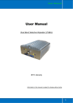
Rover AMP, LLC 9625 Wes Kearney Way • Riverview, FL 33578 • 866.232.7683 User Manual Wide Tri Band Booster (30dBm) Information in this manual is subject to change without notice LATAM & EMEA Tel France: (33) 01 56 83 72 30 Tel Mobile: +34 607 92 18 43 www.RoverAMP.com All http://www.cht-supply.com Exclusive distributor in Europe, Africa and Latin America rights reserved 1 Rover AMP, LLC 9625 Wes Kearney Way • Riverview, FL 33578 • 866.232.7683 Table of Contents 1 Description................................................................................................. 3 2 Technical Specifications............................................................................. 4 3 System Diagram ........................................................................................ 5 4 Product Features ....................................................................................... 6 5 Applications Example ................................................................................ 6 6 5.1 Minimum Signal Levels .................................................................... 7 5.2 How to check your signal levels ....................................................... 8 5.3 Custom Applications ......................................................................... 8 5.4 Isolation and Separation................................................................... 9 Production Operation ............................................................................... 11 6.1 Notices ........................................................................................... 11 6.2 Installation ...................................................................................... 11 6.3 Commissioning ............................................................................... 12 Important Notice Don’t power on Power supply for repeater before donor and service antenna connects to repeater. LATAM & EMEA Tel France: (33) 01 56 83 72 30 Tel Mobile: +34 607 92 18 43 www.RoverAMP.com All http://www.cht-supply.com Exclusive distributor in Europe, Africa and Latin America rights reserved 2 Rover AMP, LLC 9625 Wes Kearney Way • Riverview, FL 33578 • 866.232.7683 1 Description The wide triple band booster (POTRP30) is a bi-directional amplifier used to enhance signals between a mobile and a base station. This repeater type is used for digital telecommunication system: 1) -It picks up the strongest signal from BTS via the External Antenna, 2) -Linearly amplifies the signal and then retransmits it via the Indoor Signal Distribution System to the weak/blind coverage area. 3) -And the mobile signal is also amplified and retransmitted to the BTS via the opposite direction. It is commonly used in the area there are three type of mobile network, such as GSM/ /DCS/UMTS. It will reduce site deployment cost by using one tri band donor antenna, one tri band service antenna, and tri band repeaters in one enclosure. It is applied to small, medium-size areas such as corporation office, shop mall, bus station, factory etc. This model booster is commonly used in situations where large numbers of frequency carriers are to be repeated or when base station synthesized frequency hopping is used. LATAM & EMEA Tel France: (33) 01 56 83 72 30 Tel Mobile: +34 607 92 18 43 www.RoverAMP.com All rights reserved http://www.cht-supply.com Exclusive distributor in Europe, Africa and Latin America 3 Rover AMP, LLC 9625 Wes Kearney Way • Riverview, FL 33578 • 866.232.7683 This model booster does not separate out specific carriers but amplify and retransmit all signals within a defined frequency band. Inter-modulation distortion caused by band selective repeaters usually means that lower output power per carrier can be realized compared to channel selective repeaters. 2 Technical Specifications Band A Network(Customized) Band B Band C GSM900 DCS1800 UMTS2100 Uplink 55dB 55dB 55dB Downlink 70dB 70dB 70dB Uplink 30dBm 30dBm 30dBm Downlink 15dBm 15dBm 15dBm Gain Output Power Gain Adjust Scope MGC≥30 Gain Adjust Step 1dB Gain Adjust precision 0~10dB/±1dB#10~20dB/±1.5dB#20~31dB/±2dB Band Ripple ±4 ALC Scope 20dB Frequency Error ≤±0.05 I/O Impedance 50Ω/N connector VSWR ≤2 Noise figure ≤5 Spurious Emission ≤-36dBm@9KHz~1GHz/≤-30dBm@1~12.75GHz IM3 -40dBc Delay ≤0.5μs Max Input Power Level(1minute) -10dBm RF Connector N-Type (Female) Temperature Range Operation: -25°C ~ + 55°C;Storage: -30°C ~ +60°C Relative humidity 5~95% RH Power consumption 30W Power Supply AC220V Power Supply(Customized) AC220V±10% Power Supply Socket(Customized) Connector Type B Weight 3.5kg Shipment Dimensions 250mm X 300mm X 30 mm Shipment Weight 5.0kg UL LED Indicator DL LED - Green flash - Red flash - Green flash - Red flash 60Hz @ AC power on @ output power>25dBm @ output power>5dBm @ output power>15dBm LATAM & EMEA Tel France: (33) 01 56 83 72 30 Tel Mobile: +34 607 92 18 43 www.RoverAMP.com All rights reserved http://www.cht-supply.com Exclusive distributor in Europe, Africa and Latin America 4 Rover AMP, LLC 9625 Wes Kearney Way • Riverview, FL 33578 • 866.232.7683 3 System Diagram The RF link (donor) towards the base station is typically fed from an outdoor antenna while the coverage area is fed by an indoor antenna The signal from the base station is received via the wide band Donor antenna, then forwarded through a combiner filter (QPX), is amplified in a low noise amplifier (LNA), and enters the band selective amplifier board (BSA). The first mixer stage on the BSA amplifier board, which is controlled by a synthesizer, converts the received frequency down to the IF frequency. The signal is then filtered by an IF SAW band-pass filter and amplified before it is fed to the second mixer stage, controlled by the same synthesizer as the previous one, for converting back to the original frequency. The output signal from the mixer is then amplified in the power amplifier, which is controlled by the CU(Control Unit board).The output LATAM & EMEA Tel France: (33) 01 56 83 72 30 Tel Mobile: +34 607 92 18 43 www.RoverAMP.com All rights reserved http://www.cht-supply.com Exclusive distributor in Europe, Africa and Latin America 5 Rover AMP, LLC 9625 Wes Kearney Way • Riverview, FL 33578 • 866.232.7683 signal passes a combiner filter (QPX), before it is fed to the wide band MS antenna which retransmits the signal at the same frequency to the aim areas. 4 Product Features High gain>70dB, High output power 30dBm Light weight, small dimensions, easy to install Easy set DL/UL gain via local PIN switch manually, Gain adjustment of uplink and downlink; gain adjust step is 1dB and the adjust scope is 30dB. Smart Automatic Level Control (ALC) to reduce interference to BTS Linear power amplification to effectively suppress inter-modulation and spurious emission An alarm interface with unique color LEDs to indicate power supply and signal level of uplink and downlink Simple installation with external AC/DC adapter Dual ports and full duplex design 5 Applications Example LATAM & EMEA Tel France: (33) 01 56 83 72 30 Tel Mobile: +34 607 92 18 43 www.RoverAMP.com All rights reserved http://www.cht-supply.com Exclusive distributor in Europe, Africa and Latin America 6 Rover AMP, LLC 9625 Wes Kearney Way • Riverview, FL 33578 • 866.232.7683 1) The signal strength (includes external antenna) from external BTS must be 5dB larger than from neighbor BTS lists and signal level>-50dBm, so the repeater can amplifier in high efficiency with full output power. 2) The External antenna should have line of sight (LOS) with the BTS antenna. If the signal strength is adequate, LOS may in some cases not be necessary. 3) Donor antenna gains are typically 9 to 14 dB, and have a horizontal and vertical beam width of less than 30° to correctly select the donor BTS. 4) There is large physical separation between the antennas in order to prevent degradation of signal quality and risk of oscillation (Antenna isolation). Ways to achieve this can be usage of highly directional antennas with good front-to-back interference ratio or external shielding between the antennas (For example, your building has a metal roof and you install the External antenna above the roof and the Coverage antenna below the roof.). Another option is to use a Frequency Translating Repeater or ICS repeater. 5.1 Minimum Signal Levels You must have a minimum signal level in the place where you would install the External antenna. Failure to provide sufficient input signal will only result in a poor coverage inside the building for this repeater system. LATAM & EMEA Tel France: (33) 01 56 83 72 30 Tel Mobile: +34 607 92 18 43 www.RoverAMP.com All http://www.cht-supply.com Exclusive distributor in Europe, Africa and Latin America rights reserved 7 Rover AMP, LLC 9625 Wes Kearney Way • Riverview, FL 33578 • 866.232.7683 5.2 How to check your signal levels To check your signal levels, use the phone in the place where antenna be install (on the roof) and observe the signal bars on the phone. It is also helpful to be on a call for immediate registration of the signal/reception. Carefully walk around the roof with the phone to see where the signal is best. The External (outside) antenna should be placed in the location where you get the most signal. 5 Bars 4 Bars 3 Bars 2 Bars 1 Bars NOKIA NONE >-85dBm -85~-90dBm -90~-95dBm -95~-100dBm Anycall >-85dBm -85~-90dBm -90~-95dBm -95~-100dBm -100~-105dBm Motorola >-80dBm -80~-90dBm -90~-95dBm -95~-100dBm -100~-105dBm Simens NONE >-70dBm -70~-80dBm -80~-90dBm -90~-100dBm Errison >-75dBm -75~-85dBm -85~-90dBm -90~-95dBm -95~-105dBm SAGEM >-80dBm -80~-90dBm -90~-95dBm -95~-105dBm -110~-105dBm It is important to investigate and understand what is causing your reception difficulties. If your building is made of concrete, steel, steel roof, copper roof, brick, aluminum siding, concrete roofing tiles, metal roofing tiles or any other signal stopping material, a repeater is usually the ideal solution for your situation. Signal outside is 3-5 bars and falls off when you enter the building. This is an indicator that the building is the problem and a repeater system will usually solve that problem by bringing that reception from the outside to cover the inside of your building. 5.3 Custom Applications Most homes or buildings are easily covered by one of our base repeater systems. Some buildings are larger or have multiple areas inside that need coverage. You may need longer cables, more than 2 coverage antennas or other items in order to fully cover your building. We can make (almost) any cable length and can help design a system that fits your application. LATAM & EMEA Tel France: (33) 01 56 83 72 30 Tel Mobile: +34 607 92 18 43 www.RoverAMP.com All rights reserved http://www.cht-supply.com Exclusive distributor in Europe, Africa and Latin America 8 Rover AMP, LLC 9625 Wes Kearney Way • Riverview, FL 33578 • 866.232.7683 5.4 Isolation and Separation Isolation refers to the proper distance or separation needed to keep the Donor antenna signal pattern and the Coverage antenna signal pattern away from each other. Isolation becomes particularly problematic when Omni-directional antennas are used for both the Donor and the Coverage antennas. Since these antennas transmit in a circle (or more accurately a sphere) it is very easy for these spheres to overlap and thus negate the repeater system. Antenna isolation is an essential issue for the performance of a repeater. As a repeater only amplifies a received signal, it can act as an oscillator under certain circumstances. The feedback path in this amplifier system is the two antennas: coverage antenna and donor antenna. In order to prevent oscillation of the system, the feedback must be lower than the amplifier’s gain. This loss in the feedback path is called the Antenna Isolation. It must be 15 dB higher than the repeater gain to guarantee an adequate protection against self-oscillation of the repeater. Isolation(dB)=Tx- Riso(dB) Several factors have influence on the antenna isolation: 1) Antenna pattern (Horizontal and vertical) The optimum is a combination of donor and coverage antennas that are mounted the way that there is a null in the antenna pattern in the direction pointing towards the LATAM & EMEA Tel France: (33) 01 56 83 72 30 Tel Mobile: +34 607 92 18 43 www.RoverAMP.com All http://www.cht-supply.com Exclusive distributor in Europe, Africa and Latin America rights reserved 9 Rover AMP, LLC 9625 Wes Kearney Way • Riverview, FL 33578 • 866.232.7683 other antenna. A null means minimum antenna gain in the specified direction. As both antennas are usually mounted in opposite directions, it is useful to chose both donor and coverage antenna types that have a high front-to-back ratio. 2) Vertical separation Typical antennas that are used for repeater sites have a narrower aperture in the vertical antenna pattern, the vertical distance of the antenna influences the isolation of the antenna system. In a typical configuration, when both antennas are mounted on a pole, there is a null in the antenna pattern pointing vertically up and down from the antenna’s feeding point. If there is a horizontal separation between the antennas, additional lobes in the vertical antenna pattern have to be taken into account. 3) Environment of both antennas The environment of the antennas is a very important factor. The reflection and attenuation properties of all materials near the antenna can influence the antenna isolation drastically. - The waves transmitted by antennas are reflected by surfaces, depending on the materials. If there is a reflection from a building towards the pole with the mounted antennas, this can decrease the antenna isolation by more than 10 dB. - The material of the tower itself has also an effect on the isolation: If both antennas are mounted on a tower made of concrete, this improves the antenna isolation, as signals are attenuated and reflected by the material of the tower. A steel grid tower however might not increase antenna isolation particularly, as the distances between the single elements might be bigger than half a wavelength, which means that radiated power can pass the tower almost unattenuated. In this case, antenna isolation is more dependent on the antenna patterns. Shielding grids mounted near the antennas have also an effect on the isolation. Generally, isolation can be improved using a shielding grid by approximately 5 dB. This depends on the shape of the shielding grid. Grids that are shaped according to the antenna outlook are better than simple ones. LATAM & EMEA Tel France: (33) 01 56 83 72 30 Tel Mobile: +34 607 92 18 43 www.RoverAMP.com All http://www.cht-supply.com Exclusive distributor in Europe, Africa and Latin America rights reserved 10 Rover AMP, LLC 9625 Wes Kearney Way • Riverview, FL 33578 • 866.232.7683 6 Production Operation 6.1 Notices Follow below safety items carefully before installation, implementation, maintenance and operation for this product Repeater amplifies BTS uplink and downlink signal, it can extend BTS coverage area in downlink, but also effect BTS receive sensitivities in uplink. BS and MS port must be connected to donor antenna and service antenna when powers supply on; otherwise the equipment will be damage for long term use. When use repeater for outdoor, the distance between donor antenna and service antenna must be >20metes, otherwise the repeater will be damage because isolation problem for long term use. Donor antenna need to be lighting proof and lighting rod need to be install for donor antenna installation pole outside Check input power, require input power less than maximum input power of repeater, otherwise the repeater cannot work well. Keep clear for label and indicator on surface of repeater to be identified. 6.2 Installation Installing a repeater system is really quite simple. The most difficult task in installing the system is running the cable and does connectors. Step 1: Start by taking your phone up to the roof or other location outside to find where the signal is strongest. Step 2: Temporarily mount the Donor (outside) antenna in that location. You may need to adjust and move the antenna later. Step 3: Run coaxial cable into the building to a convenient location where you can also get standard 220VAC power for the repeater. LATAM & EMEA Tel France: (33) 01 56 83 72 30 Tel Mobile: +34 607 92 18 43 www.RoverAMP.com All rights reserved http://www.cht-supply.com Exclusive distributor in Europe, Africa and Latin America 11 Rover AMP, LLC 9625 Wes Kearney Way • Riverview, FL 33578 • 866.232.7683 Step 4: Place the repeater in that location and connect the coaxial cable to the Donor Side of the repeater and the donor antenna. Step 5: Mount your coverage (inside) antenna in a productive location. You may need to adjust or move the antenna later. Step 6: Connect coaxial cable between the coverage antenna and the repeater output port. Step 7: Power up the system and check for signal inside the building. If needed, tune system by moving and or pointing the Donor and Coverage antennas until they get the most signal possible. Step 8: Secure all antennas and cables, securely mount the repeater and clean up the installation. 6.3 Commissioning After switch on power supply, please check indication LED as following items. - You can switch attenuation value by using repeater side switch, If you want to set attenuation 18, you push switch PIN 4 and switch PIN1 on. - Make sure the repeater full output power LED (Downlink output power) is on when finishes commissioning. LATAM & EMEA Tel France: (33) 01 56 83 72 30 Tel Mobile: +34 607 92 18 43 www.RoverAMP.com All http://www.cht-supply.com Exclusive distributor in Europe, Africa and Latin America rights reserved 12 Rover AMP, LLC 9625 Wes Kearney Way • Riverview, FL 33578 • 866.232.7683 - And set UL ATT> DL ATT+5dB to balance the downlink and uplink and limited the interference to BTS in uplink direction. - You can change donor antenna direction or installation position to get bigger signal; - You can set attenuation to add or reduce repeater gain; or you can check cable and connector link status to reduce cable loss and insert loss between repeater and antenna. Licensed under Motorola Mobility LATAM & EMEA Tel France: (33) 01 56 83 72 30 Tel Mobile: +34 607 92 18 43 www.RoverAMP.com All rights reserved http://www.cht-supply.com Exclusive distributor in Europe, Africa and Latin America 13