1
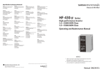
HF-320α
Operating and Maintenance Manual
HF-320α Series
Single phase input 200V class 0.2~2.2kW
Three phase input 200V class 0.2~7.5kW
Three phase input 400V class 0.4~7.5kW
NOT IC E
1. Make s ure that this operating and maintenance
manual is delivered to the end user of inverter unit.
2. R ead this manual before ins talling or operating
the inverter unit, and s tore it in a s afe place for
reference.
Home page http://www.shi.co.jp/ptc/
Specifications, dimensions and other items in the
catalog are subject to change without notice.
DM2001E-1.0
2004.9
Operating and Maintenance Manual˴DM2001E-1.0
S afety precaution
Introduction
C ontents
R ead firs t
C onnection equipment
Operations
B as ic HF -320 α
operations
B as ic parameters
E xtended parameters
Applied operations
Monitoring the
operation s tatus
T aking meas ures
to s atis fy the
C E directive
P eripheral devices
T able of parameters
and data
S pecifications
B efore making a s ervice
call-T rip information and
remedies
Ins pection and
maintenance
Warranty
Dis pos al of the inverter
I.
I
Safety precautions
The items described in these instructions and on the inverter itself are very important so that you can use the inverter safely prevent injury to yourself and other people around you as well as prevent damage to property in the
area. Thoroughly familiarize yourself with the symbols and indications shown below and then continue to read the
manual. Make sure that you observe all warnings given.
Explanation of markings
Marking
Meaning of marking
Danger
Indicates that errors in operation may lead to death or serious injury.
Warning
Indicates that errors in operation may lead to injury (*1) to people or that these errors may
cause damage to physical property. (*2)
(*1) Such things as injury, burns or shock that will not require hospitalization or long periods of outpatient treatment.
(*2) Physical property damage refers to wide-ranging damage to assets and materials.
Meanings of symbols
Marking
Meaning of marking
Indicates prohibition (Don't do it).
What is prohibited will be described in or near the symbol in either text or picture form.
Indicates something mandatory (must be done).
What is mandatory will be described in or near the symbol in either text or picture form.
Indicates danger.
What is dangerous will be described in or near the symbol in either text or picture form.
Indicates warning.
What the warning should be applied to will be described in or near the symbol in either text or picture form.
■ Limits in purpose
This inverter is used for controlling speeds of three-phase induction motors in general industrial use.
Safety precautions
The inverter cannot be used in any device that would present danger to the human body or from which
malfunction or error in operation would present a direct threat to human life (nuclear power control device, aviation and space flight control device, traffic device, life support or operation system, safety device, etc.). If the inverter is to be used for any special purpose, first get in touch with the people in
charge of sales.
This product was manufactured under the strictest quality controls but if it is to be used in critical equipment, for example, equipment in which errors in malfunctioning signal output system would cause a major accident, safety devices must be installed on the equipment.
Do not use the inverter for loads other than those of properly applied three-phase induction motors in
general industrial use. (Use in other than properly applied three-phase induction motors may cause an
accident.)
1
I
■ General Operation
Danger
See item
• Never disassemble, modify or repair.
This can result in electric shock, fire and injury. For repairs, call your sales agency.
2.
• Never remove the front cover when power is on or open door if enclosed in a cabinet.
The unit contains many high voltage parts and contact with them will result in electric shock.
• Don't stick your fingers into openings such as cable wiring hole and cooling fan covers.
This can result in electric shock or other injury.
• Don't place or insert any kind of object into the inverter (electrical wire cuttings, rods, wires).
This can result in electric shock or fire.
• Do not allow water or any other fluid to come in contact with the inverter.
This can result in electric shock or fire.
• Turn power on only after attaching the front cover or closing door if enclosed in a cabinet.
If power is turned on without the front cover attached or closing door if enclosed in a cabinet. This can result in electric shock or other injury.
• If the inverter begins to emit smoke or an unusual odor, or unusual sounds, immediately
turn power off.
If the equipment is continued in operation in such a state, the result may be fire. Call your
local sales agency for repairs.
• Always turn power off if the inverter is not used for long periods of time since there is a
possibility of malfunction caused by leaks, dust and other material. If power is left on with
the inverter in that state, it may result in fire.
2.1
Disassembly
prohibited
Prohibited
Mandatory
Warning
2.
2.
2.
2.1
3.
3.
See item
• Do not touch heat radiating fins or discharge resistors.
These device are hot, and you'll get burned if you touch them.
3.
• Avoid operation in any location where there is direct spraying of the following solvents or
other chemicals.
The plastic parts may be damaged to a certain degree depending on their shape, and
there is a possibility of the plastic covers coming off and the plastic units being dropped.
If the chemical or solvent is anything other than those shown below, please contact us in
advance.
(Table 1) Examples of applicable chemicals
(Table 2) Examples of unapplicable
and solvents
chemicals and solvents
Acetic acid (density of 10% or less)
Acetone
Hydrochloric acid (density of 10% or less)
Benzene
Sulfuric acid (density of 10% or less)
Chloroform
Sodium chloride
Ethylene chloride
Hexane
Ethyl acetate
Triethylene glycol
Glycerin
Tetrachloroethylene
Trichloroethylene
Xylene
1.4.4
Prohibited
contact
Prohibited
2
■ Transportation & installation
I
Danger
Prohibited
Mandatory
• Do not install or operate the inverter if it is damaged or any component is missing.
This can result in electric shock or fire. Please consult your local sales agency for repairs.
Call your local sales agency for repairs.
• Do not place any inflammable objects nearby.
If a flame is emitted due to malfunction, it may result in a fire.
• Do not install in any location where the inverter could come into contact with water or
other fluids.
This can result in electric shock or fire.
• Must be used in the environmental conditions prescribed in the instruction manual.
Use under any other conditions may result in malfunction.
• Mount the inverter on a metal plate.
The rear panel gets very hot. If installation is in an inflammable object, this can result in
fire.
• Do not operate with the front panel cover removed. This can result in electric shock. Failure to do so can lead to risk of electric shock and can result in death or serious injury.
• An emergency stop device must be installed that fits with system specifications (e.g. shut
off input power then engage mechanical brake). Operation cannot be stopped immediately
by the inverter alone, thus risking an accident or injury.
• All options used must be those specified by Sumitomo.
The use of any other option may result in an accident.
Warning
Prohibited
Mandatory
• When transporting or carrying, do not hold by the front panel covers.
The covers may come off and the unit will drop out resulting in injury.
• Do not install in any area where the unit would be subject to large amounts of vibration.
That could result in the unit falling, resulting in injury.
• The main unit must be installed on a base that can bear the unit's weight.
If the unit is installed on a base that cannot withstand that weight, the unit may fall resulting in injury.
• If braking is necessary (to hold motor shaft), install a mechanical brake.
The brake on the inverter will not function as a mechanical hold, and if used for that purpose, injury may result.
See item
1.4.4
1.4.4
2.
1.4.4
1.4.4
1.4.4
1.4.4
1.4.4
See item
2.
1.4.4
1.4.4
1.4.4
■ Wiring
Danger
Prohibited
• Do not connect input power to the output (motor side) terminals (U/T1,V/T2,W/T3).
That will destroy the inverter and may result in fire.
• Do not connect resistors to the DC terminals (across P(+)-N(-) or P1-N(-)).
That may cause a fire.
Connect a resistor in accordance with 6.13.4.
• Within ten minutes after turning off input power, do not touch wires of devices (MCCB)
connected to the input side of the inverter.
That could result in electric shock.
3
See item
2.2
2.2
2.2
I
Danger
Mandatory
• Electrical construction work must be done by a qualified expert.
Connection of input power by someone who does not have that expert knowledge may result in fire or electric shock.
• Connect output terminals (motor side) correctly.
If the phase sequence is incorrect, the motor will operate in reverse and that may result in
injury.
• Wiring must be done after installation.
If wiring is done prior to installation that may result in injury or electric shock
• The following steps must be performed before wiring.
(1) Turn off all input power.
(2) Wait at least ten minutes and check to make sure that the charge lamp is no longer lit.
(3) Use a tester that can measure DC voltage (800VDC or more), and check to make sure
that the voltage to the DC main circuits (across P(+)-N(-)) is 45V or less.
If these steps are not properly performed, the wiring will cause electric shock.
• Tighten the screws on the terminal board to specified torque.
If the screws are not tightened to the specified torque, it may lead to fire.
• Check to make sure that the input power voltage is +10%, -15% of the rated power voltage written on the rating label (d10% when the load is 100% in continuous operation).
If the input power voltage is not +10%, -15% of the rated power voltage (d10% when the
load is 100% in continuous operation) this may result in fire.
• Ground must be connected securely.
If the ground is not securely connected, it could lead to electric shock or fire when a
malfunction or current leak occurs.
See item
2.1
2.1
2.1
2.1
2.1
1.4.4
2.1
2.2
Be Grounded
Warning
• Do not attach equipment (such as noise filters or surge absorbers) that have built-in capacitors to the output (motor side) terminals.
That could result in a fire.
See item
2.1
Prohibited
■ Operations
Danger
Prohibited
Mandatory
• Do not touch inverter terminals when electrical power is going to the inverter even if the
motor is stopped.
Touching the inverter terminals while power is connected to it may result in electric shock.
• Do not touch switches when the hands are wet and do not try to clean the inverter with a
damp cloth.
Such practices may result in electric shock.
• Do not go near the motor in alarm-stop status when the retry function is selected.
The motor may suddenly restart and that could result in injury.
Take measures for safety, e.g. attaching a cover to the motor, against accidents when the motor unexpectedly restarts.
• Turn input power on after attaching the front cover.
When storing inside the cabinet and using with the front cover removed, always close the
cabinet doors first and then turn power on. If the power is turned on with the front cover or
the cabinet doors open, it may result in electric shock.
• Make sure that operation signals are off before resetting the inverter after malfunction.
If the inverter is reset before turning off the operating signal, the motor may restart
suddenly causing injury.
4
See item
3.
3.
3.
3.
3.
Warning
• Observe all permissible operating ranges of motors and mechanical equipment. (Refer to
the motor's instruction manual.)
Not observing these ranges may result in injury.
See item
3.
Prohibited
When sequence for restart after a momentary failure is selected (inverter)
Warning
Mandatory
• Stand clear of motors and mechanical equipment.
If the motor stops due to a momentary power failure, the equipment will start suddenly after power recovers. This could result in unexpected injury.
• Attach warnings about sudden restart after a momentary power failure on inverters, motors and equipment for prevention of accidents in advance.
See item
6.12.1
6.12.1
When retry function is selected (inverter)
Warning
Mandatory
• Stand clear of motors and equipment.
If the motor and equipment stop when the alarm is given, selection of the retry function will
restart them suddenly after the specified time has elapsed. This could result in unexpected
injury.
• Attach warnings about sudden restart in retry function on inverters, motors and equipment
for prevention of accidents in advance.
See item
6.12.3
6.12.3
Maintenance and inspection
Danger
See item
• Do not replace parts.
This could be a cause of electric shock, fire and bodily injury. To replace parts, call the local sales agency.
14.2
• The equipment must be inspected every day.
If the equipment is not inspected and maintained, errors and malfunctions may not be discovered and that could result in accidents.
• Before inspection, perform the following steps.
(1) Turn off all input power to the inverter.
(2) Wait at least ten minutes and check to make sure that the charge lamp is no longer lit.
(3) Use a tester that can measure DC voltages (800VDC or more), and check to make
sure that the voltage to the DC main circuits (across P(+)-N(-)) is 45V or less.
If inspection is performed without performing these steps first, it could lead to electric
shock.
14.
Prohibited
Mandatory
5
14.
I
I
Disposal
Warning
Mandatory
See item
• If you throw away the inverter, have it done by a specialist in industry waste disposal(*).
If you throw away the inverter by yourself, this can result in explosion of capacitor or produce noxious gases, resulting in injury.
(*) Persons who specialize in the processing of waste and known as "industrial waste product collectors and transporters" or "industrial waste disposal persons. "If the collection,
transport and disposal of industrial waste is done by someone who is not licensed for
that job, it is a punishable violation of the law. (Laws in regard to cleaning and processing
of waste materials)
16.
Attach warning labels
Shown here are examples of warning labels to prevent, in advance, accidents in relation to inverters, motors and other
equipment.
Be sure to affix the caution label where it is easily visible when selecting the auto-restart function (6.13.1) or the retry
function (6.13.3).
If the inverter has been programmed for restart
sequence of momentary power failure, place warning
labels in a place where they can be easily seen and
read.
(Example of warning label)
If the retry function has been selected, place warning
labels in a location where they can be easily seen and
read.
(Example of warning label)
Warning (Functions programmed for retry)
Warning (Functions programmed for restart)
Do not go near motors and equipment.
Motors and equipment that have stopped
temporarily after an alarm will restart suddenly
after the specified time has elapsed.
Do not go near motors and equipment.
Motors and equipment that have stopped temporarily after momentary power failure will restart
suddenly after recovery.
6
II. Introduction
Thank you for your purchase of the Sumitomo "HF-320ǩ” inverter.
Please be informed that CPU version will be frequently upgraded.
■ Features
1. Built-in noise filter
1)
2)
3)
All models in both the 200V and 400V series have a noise filter inside.
Compliant with European CE marking standard
Reduces space requirements and cuts down on time and labor needed in wiring.
2. Simple operation
1)
2)
Automatic functions (torque boost acceleration/deceleration time, function programming)
Just by wiring the motor to the power supply allows instant operation without the need to program parameters.
The potentiometer dial and the RUN/STOP button allow easy operation.
3. Superior basic performance
1)
2)
3)
4)
5)
200% or more starting torque
Smooth operation : Reduced rotation ripple through the use of Sumitomo's unique dead-band compensation.
Built-in current surge suppression circuit : Can be safely connected even if power load is low.
Maximum 500Hz high frequency output : Optimum for use with high speed motors such as those in
lumber machinery and milling machines.
Maximum carrier frequency : 16kHz quiet operation
Sumitomo's unique PWM control reduces noise at low carrier.
4. Globally compatible
1)
2)
3)
Compatible with 240V and 500V power supplies
Conforms to CE marking and with UL and CSA.
Sink/source switching of control input/output.
5. Options allow use with a wide variety of applications
•
•
•
•
Internal communications devices (RS485, Modbus RTU, DeviceNET, LonWorks)(Under preparation)
Extension panel/Parameter writer
Foot-mounted type noise reduction filter (EMC directive: For class A and class B) (Under preparation)
Other options are common to all models
7
II
Contents
I
Safety precautions......................................................................................................................................................... 1
II
Introduction.................................................................................................................................................................... 7
1. Read first ....................................................................................................................................................................... A-1
1.1
Check product purchase.................................................................................................................................... A-1
1.2
1.3
1.4
Contents of the product ..................................................................................................................................... A-3
Names and functions......................................................................................................................................... A-4
Notes on the application .................................................................................................................................... A-16
2. Connection equipment................................................................................................................................................... B-1
2.1
Cautions on wiring ............................................................................................................................................. B-1
2.2
Standard connections ........................................................................................................................................ B-3
2.3
Description of terminals ..................................................................................................................................... B-6
3. Operations..................................................................................................................................................................... C-1
3.1
Simplified operation of the HF-320α................................................................................................................. C-2
3.2
How to operate HF-320α.................................................................................................................................. C-7
4. Basic HF-320α operations............................................................................................................................................ D-1
4.1
How to set parameters....................................................................................................................................... D-3
5. Basic parameters........................................................................................................................................................... E-1
5.1
Setting acceleration/deceleration time ............................................................................................................... E-1
5.2
Increasing starting torque .................................................................................................................................. E-3
5.3
Specifying an operation mode, using parameters.............................................................................................. E-7
5.4
Selection of operation mode .............................................................................................................................. E-8
5.5
Meter setting and adjustment ............................................................................................................................ E-10
5.6
Standard default setting ..................................................................................................................................... E-13
5.7
Forward/reverse run selection (operation panel operation) ............................................................................... E-14
5.8
Maximum frequency .......................................................................................................................................... E-15
5.9
Upper limit and lower limit frequencies .............................................................................................................. E-15
5.10 Base frequency.................................................................................................................................................. E-16
5.11 Selecting control mode ...................................................................................................................................... E-17
5.12 Manual torque boost - increasing torque boost at low speeds........................................................................... E-22
5.13 Setting the electronic thermal ............................................................................................................................ E-22
5.14 Preset-speed operation (speeds in 15 steps) .................................................................................................... E-26
6. Extended parameters .................................................................................................................................................... F-1
6.1
Input/output parameters..................................................................................................................................... F-1
6.2
Input signal selection ......................................................................................................................................... F-5
i
6.3
Terminal function selection.................................................................................................................................F-7
6.4
Basic parameters 2 ............................................................................................................................................F-15
6.5
Frequency priority selection ...............................................................................................................................F-16
6.6
6.7
Operation frequency...........................................................................................................................................F-23
DC braking .........................................................................................................................................................F-24
6.8
Auto-stop in case of lower-limit frequency continuous operation .......................................................................F-27
6.9
Jog run mode .....................................................................................................................................................F-28
6.10
Jump frequency-jumping resonant frequencies .................................................................................................F-30
6.11
6.12
6.13
6.14
6.15
6.16
6.17
6.18
6.19
6.20
6.21
6.22
6.23
Preset-speed operation frequencies ..................................................................................................................F-31
PWM carrier frequency ......................................................................................................................................F-31
Trip-less intensification.......................................................................................................................................F-33
Drooping control.................................................................................................................................................F-44
Braking setting functions....................................................................................................................................F-45
Conducting PID control ......................................................................................................................................F-45
Setting motor constants .....................................................................................................................................F-50
Acceleration/deceleration Patterns 2 and 3........................................................................................................F-54
Protection functions............................................................................................................................................F-60
Adjustment parameters ......................................................................................................................................F-72
Operation panel parameter ................................................................................................................................F-74
Communication function (Common serial) .........................................................................................................F-81
Parameters for options.......................................................................................................................................F-86
7. Applied operation ...........................................................................................................................................................G-1
7.1
Setting the operation frequency .........................................................................................................................G-1
7.2
Setting the operation mode ................................................................................................................................G-5
8. Monitoring the operation status......................................................................................................................................H-1
8.1
Status monitor mode ..........................................................................................................................................H-1
8.2
Display of trip information...................................................................................................................................H-6
9. Taking measures to satisfy the CE directive...................................................................................................................I-1
9.1
How to cope with the CE directive .....................................................................................................................I-1
10. Peripheral devices..........................................................................................................................................................J-1
10.1 Selection of wiring materials and devices ..........................................................................................................J-1
10.2 Installation of a magnetic contactor....................................................................................................................J-3
10.3 Installation of an overload relay..........................................................................................................................J-4
10.4 Optional external devices...................................................................................................................................J-5
11. Table of parameters and data.........................................................................................................................................K-1
11.1 User parameters ................................................................................................................................................K-1
11.2 Basic parameters ...............................................................................................................................................K-1
11.3 Extended parameters.........................................................................................................................................K-4
ii
12. Specifications................................................................................................................................................................. L-1
12.1
Models and their standard specifications........................................................................................................... L-1
12.2
Outside dimensions and mass........................................................................................................................... L-4
13. Before making a service call - Trip information and remedies ....................................................................................... M-1
13.1
Trip causes/warnings and remedies .................................................................................................................. M-1
13.2
Restoring the inverter from a trip ....................................................................................................................... M-6
13.3
If the motor does not run while no trip message is displayed ............................................................................ M-7
13.4
How to determine the causes of other problems ............................................................................................... M-8
14. Inspection and maintenance.......................................................................................................................................... N-1
14.1 Regular inspection............................................................................................................................................. N-1
14.2 Periodical inspection.......................................................................................................................................... N-2
14.3 Making a call for servicing ................................................................................................................................. N-4
14.4 Keeping the inverter in storage.......................................................................................................................... N-5
15. Warranty ........................................................................................................................................................................ O-1
16. Disposal of the inverter .................................................................................................................................................. P-1
iii
1. Read first
1.1
Check product purchase
Before using the product you have purchased, check to make sure that it is exactly what you ordered.
Warning
Mandatory
Use an inverter that conforms to the specifications of power supply and three-phase induction motor being used. If the inverter being used does not conform to those specifications, not only will
the three-phase induction motor not rotate correctly, but it may cause serious accidents through
overheating and fire.
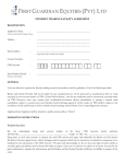
Rating label
Inverter main unit
Warning label
Pet name
Power supply
Motor capacity
HF-320
1PH-200/240V-0.75kW/1HP
Carton box
Name plate
Warning label
Name plate
Type indication label
Inverter Type
Inverter rated output capacity
Power supply
Related input current
Related output current
Model: HF3212-A20
0.2kW-0.6kVA-1/4HP
INPUT
OUTPUT
U(V)
3PH 200/240 3PH 200/240
50/60
0.5/200
F(Hz)
1.6
1.8
I(A)
S.CKT5000A FUSE CC/J 3max
Cu AWG14: 75͠
0.8Nm 7.1lb.in
Instrucution manual
This manual
A-1
Lot No.03E XXXXXXX
Serial No.XXXXXXXXXXXX
Motor Protective Device Class 10
DANGER
1
1.2
Contents of the product
Here is explained the type and form written on the label.
Type Form
1
㧴 㧲 㧟
㧞
㧝
㧞
Model
Input(AC) voltage
HF-320
series
2Ჴthree-phase 200V᳸240᳐
SᲴsingle-phase200V᳸240V
4Ჴthree-phase 380V᳸500V
㧙
㧭
㧞
㧜
Application motor
capacity
A20Ჴ0.2kW
A40Ჴ0.4kW
A75Ჴ0.75kW
1A5Ჴ1.5kW
2A2Ჴ2.2kW
3A7Ჴ3.7kW
5A5Ჴ5.5kW
7A5Ჴ7.5kW
011Ჴ11kW
015Ჴ15kW
* You can switch from one input/output logic to the other using slide switch SW1. (See 2.3.2)
Warning: Always shut power off first then check the ratings label of inverter held in a cabinet.
A-2
1.3
Names and functions
1.3.1
Outside view
Percent(%) lamp
RUN lamp
Lights when an ON command is issued but
no frequency signal is sent out. It binks
when operation is started.
Lights when a numeric
value is displayed in %.
PRG lamp
Hertz(Hz) lamp
Lights when the inverter
is in parameter setting
mode.
Blinks when the inverter
is placed in AUH Gr.U
mode.
Lights when a numeric
value is displayed in Hz.
MON lamp
Operation frequency
can be changed when
the built-in potentiometer lamp is it.
Built-in potentiometer
lamp
Lights when the inverter
is in monitor mode.
Blinks when the inverter
is placed in trip record
display mode.
MON key
Displays operation
frequency,parameters,
and error causes.
Up key
Up/Down key lamp
Store key
Pressing up or down key
when this lamp is lighted
allows the setting of
operation frequency.
Built-in potentiometer
STOP/RESET key
Down key
RUN key
RUN key lamp
Lights when the RUN
Key is enabled.
Pressing this key while
the RUN key lamp is
lights starts operation.
[Front panel 1]
A-3
Every pressing of this
key while the RUN key
lamp is it will cause a
slowdown stop.
Pressing this key while
the inverter trip reset
the inverter.
1
Unlock position mark
The front panel is unlocked when
the dot on the locking screw is on
this (upper) side.
Charge lamp
1
Indicates that high voltage is still
present within the inverter. Do not
open the terminal board cover
while this is lit.
Front panel locking screw
The inverter came with this
screw in the locked position.
So from this position, turn the
screw 90° counterclockwise
to unlock the front panel, or
turn it 90° clockwise to lock
the front panel.
The screw does not turn 360°. So
avoid damage to the screw, do
not use excessive force when
turning it.
Front panel
The front panel of the inverter or
terminal board
To avoid touching the terminal
board by mistake, be sure to
close the front panel before
starting operation.
DANGER
Lock position mark
The front panel is locked when the
dot on the locking screw is on this
(lower) side.
A-4
Top warning label
Note1)
Control cable port
Cooling fin
Communication
connector hole
Main circuit
cable port
Ventilation slit
Name plate
[Bottom]
Note 1)
[Right side]
Remove this seal when installed where the ambient temperature will rise above 40°C.
Example of the label
40˚C
50mm
A-5
1
1.3.2
Main circuit and control circuit terminal boards
1) Main circuit terminal board
When using lug connector, cover the lug connector with insulated tube, or use the insulated lug connector.
1
Screw size
tightening torque
M3.5 screw
0.9N y m
7.1lb y in
M4 screw
1.3N y m
10.7lb y in
M5 screw
2.5N y m
22.3lb y in
M6 screw
4.5N y m
40.1lb y in
HF3212-A20 ∼ A75
M3.5 screw
Shorting-bar
P1
P(+)
PR
N(-)
Screw hole of EMC plate
Note 1
Note 1: EMC plate is optional.
A-6
Grounding terminal
(M5 screw)
HF3212-1A5 ∼ 3A7
M3.5 screw (1A5 only)
M4 screw (2A2,3A7)
1
P1
P(+)
PR
N(-)
Shorting-bar
Screw hole of EMC plate
Note 1
Grounding terminal
(M5 screw)
HF321S-A20 ∼ A75
Grounding capacitor
disconnecting switch
Shorting-bar
M3.5 screw
P1
P(+)
PR
N(-)
Screw hole of EMC plate
Note 1
Note 1: EMC plate is optional.
A-7
Grounding terminal
(M5 screw)
HF321S-1A5,2A2
Grounding capacitor
disconnecting switch
M4 screw
1
P1
PR
P(+)
N(-)
Shorting-bar
Grounding terminal
(M5 screw)
Screw hole of EMC plate
Note 1
HF3214-A40 ∼ 3A7
Grounding capacitor
disconnecting switch
M4 screw
P1
P(+)
PR
N(-)
Shorting-bar
Screw hole of EMC plate
Note 1
Note 1: EMC plate is optional.
A-8
Grounding terminal
(M5 screw)
HF3212-5A5, 7A5
HF3214-5A5, 7A5
Grounding capacitor
disconnecting tap M4 screw
(HF3214 only)
1
M5 screw
PR
P1
N(-)
P(+)
Shorting-bar
Screw hole of EMC plate
Note 1
Note 1: EMC plate is optional.
A-9
Grounding terminal
(M5 screw)
HF3212-011, 015
HF3214-011, 015
Grounding capacitor
disconnecting tap M4 screw
(HF3214 only)
1
M6 screw
PR N(-)
P1
P(+)
Shorting-bar
Screw hole of EMC plate
Note 1
Grounding terminal
(M5 screw)
In case of the lug connector, cover the lug connector with insulated tube, or use the insulated lug connector.
Note 1: EMC plate is optional.
A-10
2) Grounding capacitor disconnecting switch and taps
Warning
The grounding capacitor disconnecting tap is provided with a protection cover. To avoid shock hazards,
always attach the cover after connecting or disconnecting the capacitor to or from the tap.
Mandatory
Every single-phase 200V/three-phase 400V model has a built-in high-attenuation noise filter, which is
grounded through a capacitor.
If you want to disconnect the capacitor from the grounding line to reduce the amount of leakage current,
you can do so easily using the switch or tap. Keep in mind, however, that disconnecting the capacitor
from the grounding line causes the inverter to become incompliant with the EMC directive. Also note
that the inverter must always be turned off before the capacitor is disconnected or reconnected.
3.7kW or less : Switch
To connect the capacitor from the grounding, push this
switch. (Factory default position)
To disconnect the capacitor from the grounding, pull up this
switch.
A-11
1
5.5kW or more : Tap
To disconnect the capacitor from the grounding, connect the lug
terminal to this tap.
1
To connect the capacitor from the grounding, connect the lug
terminal to this tap. (Factory default setting)
A-12
3) Control circuit terminal board
The control circuit terminal board is common to all equipment.
PCS
P24V DRV OM FRQ COM
FA
FRQ VRF
+V
V side
VRF VRF2 COM
FB
FC
RY
PCS DFL DFM DFH
I side
FR
1
RC
M3 screw
(0.5Nm)
RR RST COM
Optional connector
(RJ45)
Wire size
2
Solid wire: 0.3 ∼ 1.5㧔mm 㧕
Factory default settings of slide switches
SW1: SINK side
Stranded wire: 0.3 ∼ 1.5㧔mm2㧕
㧔AWG 22 ∼ 16㧕
Sheath strip length: 6 (mm㧕
SOURCE side
FRQ: V side
VRF: V side
Screwdriver: Small-sized flat-blade screwdriver
(Blade thickness: 0.4 mm or less, blade width: 2.2 mm or less)
See 2.3.2 for details on all terminal functions.
A-13
1.3.3
How to open the front (terminal board) cover
To wire the terminal board, remove the front lower cover in line with the steps given below.
(2)
(1)
1
Turn the locking screw on the right
side of the front panel 90q
counterclockwise to align the dot on the
screw with the unlock position mark
(upper side). To avoid damage to the
screw, Do not apply excessive force to
turn the screw more than 90qdegrees.
Pull the front panel toward you
and swing it open to the left.
A-14
1.4
Notes on the application
1.4.1
Motors
When the HF-320ǩ and the motor are used in conjunction, pay attention to the following items.
Warning
Mandatory
Use an inverter that conforms to the specifications of power supply and three-phase induction motor being used. If the inverter being used does not conform to those specifications, not only will the three-phase
induction motor not rotate correctly, but it may cause serious accidents through overheating and fire.
Comparisons with commercial power operation.
The HF-320ǩInverter employs the sinusoidal PWM system. However, the output voltage and output
current do not assume a precise sine wave, they have a distorted wave that is close to sinusoidal waveform. This is why compared to operation with a commercial power there will be a slight increase in motor temperature, noise and vibration.
Operation in the low-speed area
When running continuously at low speed in conjunction with a general purpose motor, there may be a
decline in that motor's cooling effect. If this happens, operate with the output decreased from rated load.
To carry out low-speed operation continuously at the rated torque, we recommend to use a “AF motor”
designed for use with an inverter. When operating in conjunction with a “AF motor”, you must change
the inverter's motor overload protection level to AF motor use (QNO).
Adjusting the overload protection level
The HF-320ǩInverter protects against overloads with its overload detection circuits (electronic thermal).
The electronic thermal's reference current is set to the inverter's rated current, so that it must be adjusted in line with the rated current of the general purpose motor being used in combination.
High speed operation at and above 60Hz
Operating at frequencies greater than 60Hz will increase noise and vibration. There is also a possibility
that such operation will exceed the motor's mechanical strength limits and the bearing limits so that you
should inquire to the motor's manufacturer about such operation.
Method of lubricating load mechanisms
Operating an oil-lubricated reduction gear and gear motor in the low-speed areas will worsen the lubricating effect. Check with the manufacturer of the reduction gear to find out about operable gearing area.
A-15
1
Low loads and low inertia loads
The motor may demonstrate instability such as abnormal vibrations or overcurrent trips at light loads of
50 % or under of the load percentage, or when the load's inertia moment is extremely small. If that happens reduce the carrier frequency.
Occurrence of instability
1
Unstable phenomena may occur under the load and motor combinations shown below.
㨯 Combined with a motor that exceeds applicable motor ratings recommended for the inverter
㨯 Combined with special motors
To deal with the above lower the settings of inverter carrier frequency.
㨯 Combined with couplings between load devices and motors with high backlash
When using the inverter in the above combination, use the S-pattern acceleration/deceleration function,
or when sensorless vector control is selected, adjust the speed control response/stability factor or
switch to V/f control mode.
㨯 Combined with loads that have sharp fluctuations in rotation such as piston movements
In this case, adjust the response time (inertial moment setting) during sensorless vector control or
switch to V/f control.
Braking a motor when cutting off power supply
A motor with its power cut off goes into free-run, and does not stop immediately. To stop the motor
quickly as soon as the power is cut off install an auxiliary brake. There are different kinds of brake devices, both electrical and mechanical. Select the brake that is best for the system.
Load that produces regenerative torque
When combined with a load that produces regenerative torque, the overvoltage or overcurrent protection function may be activated to trip the inverter. For this kind of situation, you must install a dynamic
braking resistor, etc. that complies with the load conditions.
Motor with brake
If a motor with brake is connected directly to the output side of the inverter, the brake will not release
because voltage at startup is low. Wire the brake circuit separately from the motor's main circuits.
MC2
MC2
B
B
MC1
MC1
IM
IM
Three-phase
power
supply
FB
FC
ST
COM
Three-phase
power supply
RY
ųųRC
MC3
MC1
MC3
MC2
MC3
MC2
Circuit Configuration 2
Circuit Configuration 1
A-16
In circuit configuration 1, the brake is turned on and off through MC2 and MC3. If the circuit is configured in some other way, the overcurrent trip may be activated because of the locked rotor current when
the brake goes into operation.
Circuit configuration 2 uses low-speed signal RY to turn on and off the brake.
Turning the brake on and off with a low-speed signal may be better in such applications as elevators.
Please confer with us before designing the system.
Measures to protect motors against surge voltages
In a system in which a 400V-class inverter is used to control the operation of a motor, very high surge
voltages may be produced, applied to the motor coils repeatedly for a long time and cause deterioration
of their insulation, depending on the cable length, cable routing and types of cables used.
Here are some examples of measures against surge voltages.
(1) Lower the inverter’s carrier frequency.
(2) Set the parameter H (Carrier frequency control mode selection) to 2 or 3.
(3) Use a motor with high insulation strength.
(4) Insert an AC reactor or a surge voltage suppression filter between the inverter and the motor.
1.4.2
Inverters
Protecting inverters from overcurrent
The inverter has an overcurrent protection function. However because the programmed current level is
set to the inverter's maximum applicable motor, if the motor is one of small capacity and it is in operation, the overcurrent level and the electronic thermal protection must be readjusted. If adjustment is
necessary, see 5-13, and make adjustments as directed.
Inverter capacity
Do not use small-capacity (kVA) inverter to control the operation of a large-capacity, motor no matter
how light the load is. Current ripple will raise the output peak current making it easier to set off the overcurrent trip.
A-17
1
Power factor improving capacitor
Power factor improving capacitors cannot be installed on the output side of the inverter. When a motor
is run that has a power factor improving capacitor attached to it, remove the capacitors. This can cause
inverter malfunction trips and capacitor destruction.
U
1
Inverter
IM
V
W
Remove the power factor improving
capacitor and surge absorber
Power factor improving capacitor
Operating at other than rated voltage
Connections to voltages other than the rated voltage described in the rating label cannot be made. If a
connection must be made to a power supply other than one with rated voltage, use a transformer to
raise or lower the voltage to the rated voltage.
Circuit interrupting when two or more inverters are used on the same power line.
MCCB1
MCCB2 (circuit interupting fuse)
INV1
MCCB3
INV2
MCCBn+1
INVn
Breaking of selected inverter
There is no fuse in the inverter's main circuit. Thus, as the diagram above shows, when more than one
inverter is used on the same power line, you must select interrupting characteristics so that only the
MCCB2 will trip and the MCCB1 will not trip when a short occurs in the inverter (INV1). When you cannot select the proper characteristics install a circuit interrupting fuse between the MCCB2 and the INV1.
If power supply distortion is not negligible
If the power supply distortion is not negligible because the inverter shares a power distribution line with
other systems causing distorted waves, such as systems with thyristors or large-capacity inverters, install an input reactor to improve the input power factor, to reduce higher harmonics, or to suppress external surges.
A-18
■ Disposal
If an inverter is no longer usable, dispose of it as industrial waste.
1.4.3
What to do about the leak current
Warning
Current may leak through the inverter's input/output wires because of insufficient electrostatic capacity on the motor with
bad effects on peripheral equipment.
The leak current's value is affected by the carrier frequency and the length of the input/output wires. Test and adopt the
following remedies against leak current.
(1) Effects of leak current across ground
Leak current may flow not just through the inverter system but also through ground wires to other systems. Leak current will cause earth leakage breakers, leak current relays, ground relays, fire alarms
and sensors to operate improperly, and it will cause superimposed noise on the CRT screen or display
of incorrect current amounts during current detection with the CT.
Power
supply
ELCB
Inverter
ELCB
Inverter
M
M
Leak current path across ground
Remedies:
1.If there is no radio-frequency interference or similar problem, detach the built-in noise filter capacitor, using the grounding capacitor disconnecting switch or tap. (See 1.3.2-2)
2.Reduce PWM carrier frequency.
The setting of PWM carrier frequency is done with the parameter H.
3. Use high frequency remedial products for earth leakage breakers. PWM carrier frequency.
4.If the sensors and CRT are affected, it can be remedied using the reduction of PWM carrier
frequency described in 1 above, but if this cannot be remedied since there is an increase in the
motor's magnetic noise, please consult with Toshiba.
A-19
1
(2) Affects of leak current across lines
Thermal relays
1
CT
Inverter
Power
supply
M
A
Leak current path across wires
(1)
Thermal relays
The high frequency component of current leaking into electrostatic capacity between inverter output wires will increase the effective current values and make externally connected thermal relays
operate improperly. If the wires are more than 50 meters long, it will be easy for the external thermal relay to operate improperly with models having motors of low rated current (several
A(ampere) or less), especially the 400V class low capacity (3.7kW or less) models, because the
leak current will increase in proportion to the motor rating.
Remedies:
1.Use the electronic thermal built into the inverter. (See 5.13)
The setting of the electronic thermal is done using parameter QNO, VJT.
2.Reduce the inverter's PWM carrier frequency. However, that will increase the motor's magnetic
noise.
The setting of PWM carrier frequency is done with the parameter H. (See 6.12)
3.This can be improved by installing 0.1µ~0.5µF - 1000V film capacitor to the input/output terminals of
each phase in the thermal relay.
U/T1
V/T2
IM
W/T3
Thermal relays
A-20
(2)
CT and ammeter
If a CT and ammeter are connected externally to detect inverter output current, the leak current's high
frequency component may destroy the ammeter. If the wires are more than 50 meters long, it will be
easy for the high frequency component to pass through the externally connected CT and be superimposed on and burn the ammeter with models having motors of low rated current (several A(ampere) or
less), especially the 400V class low capacity (3.7kW or less) models, because the leak current will increase in proportion to the motor's rated current.
1
Remedies:
1.Use a meter output terminal in the inverter control circuit.
The output current can be output on the meter output terminal (FRQ). If the meter is connected, use
an ammeter of 1mAdc full scale or a voltmeter of 7.5V-1mA full scale.
2.Use the monitor functions built into the inverter.
Use the monitor functions on the panel built into the inverter to check current values.
1.4.4
Installation
■ Installation environment
The HF-320ǩInverter is an electronic control instrument. Take full consideration to installing it in the proper
operating environment.
Danger
• Do not place any flammable substances near the HF-320ǩInverter.
If an accident occurs in which flame is emitted, this could lead to fire.
Prohibited
• Operate under the environmental conditions prescribed in the instruction manual.
Operations under any other conditions may result in malfunction.
Mandatory
Warning
• Do not install the HF-320ǩInverter in any location subject to large amounts of vibration.
This could cause the unit to fall, resulting in bodily injury.
Prohibited
Mandatory
• Check to make sure that the input power voltage is +10%, -15% of the rated power voltage written on
the rating label (±10% when the load is 100% in continuous operation) If the input power voltage is not
+10%, -15% of the rated power voltage (±10% when the load is 100% in continuous operation) this
may result in fire.
A-21
Warning
• Avoid operation in any location where there is direct spraying of the following solvents or other chemicals. The plastic parts may be damaged to a certain degree depending on their shape, and there is a
possibility of the plastic covers coming off and the plastic units being dropped. If the chemical or solvent is anything other than those shown below, please contact us in advance.
Prohibited
(Table 2)
Examples of unapplicable
chemicals and solvents
Chemical
Solvent
Phenol
Gasoline,
kerosene, light oil
Benzenesulfonic Turpentine oil
acid
Benzol
Thinner
(Table 1)
Examples of applicable chemicals
and solvents
Chemical
Solvent
Hydrochloric acid
Methanol
(density of 10% or less)
Sulfuric acid
Ethanol
(density of 10% or less)
Nitric acid
Triol
(density of 10% or less)
Caustic soda
Mesopropanol
Ammonia
Glycerin
Sodium chloride (salt)
1
Note:
•
The plastic cover has resistance to deformation by the above applicable solvents. They are
not examples for resistance to fire or explosion.
• Do not install in any location of high temperature, high humidity,
moisture condensation and freezing and avoid locations where
there is exposure to water and/or where there may be large
amounts of dust, metallic fragments and oil mist.
• Do not install in any location where corrosive gases or grinding fluids are present.
Operate in areas where ambient temperature ranges from -10°C to 50°C. Operation over 40°C is
allowed when peel off the top warning label.
50͠
5cm
5cm
Measurement position
5cm
-10͠
Note:
Measurement position
The inverter is a heat-emitting body. Make sure to provide proper space and ventilation when installing in the cabinet. When installing inside a cabinet, we recommend peel of the top seal although
40°C or less.
A-22
•
Do not install in any location that is subject to large amounts of vibration.
Note:
If the HF-320ǩInverter is installed in a location that is subject to vibration, anti-vibration measures are required.
Please consult with Sumitomo about these measures.
1
•
If the HF-320ǩInverter is installed near any of the equipment listed below, provide measures to insure
against errors in operation.
Solenoids:
Brakes:
Magnetic contactors:
Fluorescent lights:
Resistors:
Attach surge suppressor on coil.
Attach surge suppressor on coil.
Attach surge suppressor on coil.
Attach surge suppressor on coil.
Place far away from HF-320ǩInverter.
Resistors
■ How to install
Danger
• Do not install or operate the inverter if it is damaged or any component is missing.
This can result in electric shock or fire. Please consult your local sales agency for repairs. Call your local sales agency for repairs.
Prohibited
Mandatory
• Mount the inverter on a metal plate.
The rear panel gets very hot. If installation is in an inflammable object, this can result in fire.
• Do not operate with the front panel cover removed.
This can result in electric shock.
• An emergency stop device must be installed that fits with system specifications (e.g. shut off input
power then engage mechanical brake).
Operation cannot be stopped immediately by the inverter alone, thus risking an accident or injury.
• All options used must be those specified by Sumitomo.
The use of any other option may result in an accident.
Warning
Mandatory
• The main unit must be installed on a base that can bear the unit's weight.
If the unit is installed on a base that cannot withstand that weight, the unit may fall resulting in injury.
• If braking is necessary (to hold motor shaft), install a mechanical brake.
The brake on the inverter will not function as a mechanical hold, and if used for that purpose, injury
may result.
A-23
■ How to install
Install the inverter in a well-ventilated indoor place and mount it on a flat metal plate in portrait orientation.
If you are installing more than one inverter, the separation between inverters should be at least 5 centimeters, and
they should be arranged in horizontal rows. It is necessary to decrease the current if the inverter is operated at
over 40°C. For more information, refer to “Load Reduction and Thermal Environment Instruction Manual.”
•Standard installation
1
•Bad installation
10 centimeters or more
5 centimeters or more
HF-320
HF-320
5 centimeters or more
If the space on top and bottom is
less than 10 cm, the temperature
rise of the inverter increase.
It may result in malfunction.
10 centimeters or more
The space shown in the diagram is the minimum allowable space. Because air cooled equipment has cooling
fans built in on the top or bottom surfaces, make the space on top and bottom as large as possible to allow
for air passage.
Note: Do not install in any location where there is high humidity or high temperatures and where there are
large amounts of dust, metallic fragments and oil mist. If you are going to install the equipment in any
area that presents a potential problem, please consult with Sumitomo before doing so.
A-24
■ Watt loss values of the inverter and the required ventilation
About 5% of the rated power of the inverter will be lost as a result of conversion from AC to DC or from DC to
AC. In order to suppress the rise in temperature inside the cabinet when this loss becomes heat loss, the interior of the cabinet must be ventilated and cooled.
The amount of forcible air-cooling ventilation required and the necessary heat discharge surface quantity
when operating in a sealed cabinet according to motor capacity are as follows.
Voltage class
Single-phase
200V class
Three -Phase
200V class
Three-Phase
400V class
Operating motor
capacity
㧔kW㧕
0.2
0.4
0.75
1.5
2.2
0.2
0.4
0.75
1.5
2.2
3.7
5.5
7.5
11
15
0.4
0.75
1.5
2.2
3.7
5.5
7.5
11
15
Watt loss Values
Inverter type
HF321S-
HF3212-
HF3214-
A20
A40
A75
1A5
2A2
A20
A40
A75
1A5
2A2
3A7
5A5
7A5
011
015
A40
A75
1A5
2A2
3A7
5A5
7A5
011
015
Carrier
frequency
4kHz
Carrier
frequency
12kHz
23
47
74
142
239
21
43
67
131
168
330
450
576
750
942
30
44
77
103
189
264
358
490
602
29
60
88
169
270
26
54
79
150
195
374
510
635
820
1035
42
57
99
134
240
354
477
650
808
Amount of forcible air
cooling ventilation re3
quired (m /min)
Heat discharge surface
area required for sealed
2
storage cabinet(m )
0.23
0.29
0.40
0.60
0.80
0.23
0.29
0.40
0.60
0.80
1.2
1.7
2.3
3.4
4.6
0.32
0.40
0.60
0.80
1.2
1.7
2.3
3.4
4.6
0.8
1.0
1.4
2.1
2.8
0.8
1.0
1.4
2.1
2.8
4.3
6.1
8.1
12.0
16.0
1.1
1.4
2.1
2.8
4.3
6.1
8.1
12.0
16.0
Notes
1)
The heat loss for the optional external devices (input reactor, DC reactor, radio noise reduction filters,
etc.) is not included in the calorific values in the table
2)
Case of 100% Load Continuation operation.
■ Panel designing taking into consideration the effects of noise
The inverter generates high frequency noise. When designing the control panel setup, consideration must be
given to that noise. Examples of measures are given below.
• Wire so that the main circuit wires and the control circuit wires are separated. Do not place them in the
same conduit, do not run them parallel, and do not bundle them.
• Provide shielding and twisted wire for control circuit wiring.
• Separate the input (power) and output (motor) wires of the main circuit. Do not place them in the same
conduit, do not run them parallel, and do not bundle them.
• Ground the inverter ground terminals ( ).
• Install surge suppressor on any magnetic contactor and relay coils used around the inverter.
• Install noise filters if necessary.
A-25
1
■ Installing more than one unit in a cabinet
If you are installing two or more inverters in one cabinet, pay attention to the following.
• When using inverters where the ambient temperature will rise above 40°C, leave a space of 5 cm or
more between them and remove the caution label from the top of each inverter, or operate each inverter
at a current lower than the rated one. For more information, refer to “Load Reduction and Thermal Environment Instruction Manual.”
1
• Ensure a space of at least 20 centimeters on the top and bottom of the inverters.
• Install an air deflecting plate so that the heat rising up from the inverter on the bottom does not affect the
inverter on the top.
Ventilation fan
Inverter
Air deflecting plate
Inverter
A-26
2. Connection equipment
Danger
• Never disassemble, modify or repair.
This can result in electric shock, fire and injury. For repairs, call your sales agency.
Disassembly
prohibited
Prohibited
• Don't stick your fingers into openings such as cable wiring hole and cooling fan covers.
This can result in electric shock or other injury.
• Don't place or insert any kind of object into the inverter (electrical wire cuttings, rods, wires). This can
result in electric shock or fire.
• Do not allow water or any other fluid to come in contact with the inverter.
That may result in electric shock or fire.
Warning
• When transporting or carrying, do not hold by the front panel covers.
The covers may come off and the unit will drop out resulting in injury.
Prohibited
2.1
Cautions on wiring
Danger
• Never remove the front cover when power is on or open door if enclosed in a cabinet.
The unit contains many high voltage parts and contact with them will result in electric shock.
Prohibited
Mandatory
• Turn power on only after attaching the front cover or closing door if enclosed in a cabinet.
If power is turned on without the front cover attached or closing door if enclosed in a cabinet. This can
result in electric shock or other injury.
• Electrical construction work must be done by a qualified expert.
Connection of input power by someone who does not have that expert knowledge may result in fire or
electric shock.
• Connect output terminals (motor side) correctly.
If the phase sequence is incorrect, the motor will operate in reverse and that may result in injury.
• Wiring must be done after installation.
If wiring is done prior to installation that may result in injury or electric shock.
• The following steps must be performed before wiring.
(1) Shut off all input power.
(2) Wait at least ten minutes and check to make sure that the charge lamp is no longer lit.
(3) Use a tester that can measure DC voltage (800VDC or more), and check to make sure that the
voltage to the DC main circuits (across P(+)-N(-)) is 45V or less.
If these steps are not properly performed, the wiring will cause electric shock.
• Tighten the screws on the terminal board to specified torque.
If the screws are not tightened to the specified torque, it may lead to fire.
B-1
2
Danger
• Ground must be connected securely.
If the ground is not securely connected, it could lead to electric shock or fire when a malfunction or current leak occurs.
Be Grounded
Warning
2
• Do not attach devices with built-in capacitors (such as noise filters or surge absorber) to the output
(motor side) terminal.
This could cause a fire.
Prohibited
■ Preventing radio noise
To prevent electrical interference such as radio noise, separately bundle wires to the main circuit's power
terminals (R/L1, S/L2, T/L3) and wires to the motor terminals (U/T1, V/T2, W/T3).
■ Control and main power supply
The control power supply and the main circuit power supply for the HF-320α are the same.
If a malfunction or trip causes the main circuit to be shut off, control power will also be shut off. When
checking the cause of the malfunction or the trip, use the trip holding retention selection parameter. (See
6.19.3)
■ Wiring
• Because the space between the main circuit terminals is small use sleeved pressure terminals for the
connections. Connect the terminals so that adjacent terminals do not touch each other.
• For ground terminal use wires of the size that is equivalent to or larger than those given in table 10.1
and always ground the inverter (200V voltage class: D type ground [former type 3 ground]; 400V class: C
type ground [former special type 3 ground]).
Use as large and short a ground wire as possible and wire it as close as possible to the inverter.
• For the sizes of electric wires used in the main circuit, see the table in 10.1.
• The length of the main circuit wire in 10-1 should be no longer than 30 meters. If the wire is longer than
30 meters, the wire size (diameter) must be increased.
B-2
2.2
Standard connections
Danger
Prohibited
• Do not connect input power to the output (motor side) terminals (U/T1, V/T2, W/T3).
Connecting input power to the output could destroy the inverter or cause a fire.
• Do not insert a resistor between DC terminals (between P(+) and N(-), or between P1 and N(-)).
It could cause a fire.
See 6.13.4 for the connection of a resistor.
• First shut off input power and wait at least 10 minutes before touching wires on equipment (MCCB) that
is connected to inverter power side.
Touching the wires before that time could result in electric shock.
• Securely connect to ground with a ground wire.
It could lead to electric shock or fire when a malfunction or current leak occurs.
Be Grounded
B-3
2
2.2.1
Standard connection diagram 1
This diagram shows a standard wiring of the main circuit.
Standard connection diagram-sink (common:COM)
DC reactor(DCL)
*2 (option)
2
Braking resister (option)
P1
Main circuit power supply
200V class: three-phase 200-240V
-50/60Hz
400V class: three-phase 380-500V
-50/60Hz
MCCB
PR
P(+)
N(-)
Motor
R/L1
S/L2
Noise
filter
T/L3
Main circuit
*1
Protective function
activation output
MCCB (2P)
Power supply
1200᳸240V
-50/60Hz
R/L1
FC
Control
circuit
FB
HF-320α
Operation panel
FA
IM
W/T3
FR
Forward (rotation signal)
RR
Reverse (rotation signal)
RST
Reset
DFL
Preset-speed 1
DFM
Preset-speed 2
Connector for
common serial
communications DFH
S/L2
RY
*1: The T/L3 terminal is not provided
for single-phase models.
Use the R/L1 and S/L2 terminal
as input terminals.
*2: The inverter came with the P1
and the P(+) terminals shorted by
means of a shorting bar.
Before installing the DC reactor (DCL),
remove the bar.
*3: When using the DRV output terminal in
sink logic mode, short-circuit the OM and
COM terminals.
U/T1
V/T2
FRQ VRF
SW1
V
SOURSE V
RC
Preset-speed 3
Common
COM
P24V
PCS
Ry
DRV
SINK
++
Driving
signal output
OM
*3
FRQ
Meter
COM VRF VRF2
+V
COM
+ Voltage signal: 0-10V
+
Frequency
meter
(am meter)
-
(Current signal: 4-20mA)
External potentiometer (1-10k )
(or input voltage signal across VRF2-COM terminals: 0-10V)
B-4
2.2.2
Standard connection diagram 2
Standard connection diagram-source (common:P24V)
DC reactor (DCL)
*2 (option)
Braking resister (option)
P1
Main circuit power supply
200V class: three-phase 200-240V
-50/60Hz
400V class: three-phase 380-500V
-50/60Hz
MCCB
0
PR
P(+)
R/L1
S/L2
T/L3
Noise
filter
V/T2
W/T3
Main circuit
*1
R/L1
FC
FB
HF-320α
Operation panel
FA
FR
Forward (rotation signal)
RR
Reverse (rotation signal)
RST
Reset
DFL
Preset-speed 1
Connector for
common serial
communications DFM
S/L2
RY
*1: The T/L3 terminal is not provided
for single-phase models.
Use the R/L1 and S/L2 terminal
as input terminals.
*2: The inverter came with the P1
and the P(+) terminals shorted by
means of a shorting bar.
Before installing the DC reactor (DCL),
remove the bar.
*3: When using the OM output terminal in
sink logic mode, short-circuit the P24V
and COM terminals.
IM
P24V
Control
circuit
Protective function
activation output
MCCB(2P)
Power supply
1200᳸240V
-50/60Hz
Motor
U/T1
FRQ VRF
SW1
V
SOURSE V
RC
Preset-speed 2
Preset-speed 3
DFH
P24V
*3
PCS
DRV
SINK
FRQ
Meter
++
COM VRF VRF2
+V
OM
Ry
COM
Driving
signal output
+ Voltage signal: 0-10V
+
Frequency
meter
(am meter)
-
-
(Current signal: 4-20mA)
External potentiometer (1-10k )
(or input voltage signal across VRF2-COM terminals: 0-10V)
B-5
2
2.3
Description of terminals
2.3.1
Main circuit terminals
This diagram shows an example of wiring of the main circuit. Use options if necessary.
■ Power supply and motor connections
Power supply
2
HF-320α
Power lines are
connected to R.,S., and T.
Motor lines are
connected to U.,V., and W.
Motor
Non-fuse
breaker
■ Connections with peripheral equipment
No-fuse Magnetic Input AC
braker connector reactor
noise reduction
filter (Soon to be
released)
Surge suppression
filter
Inverter
R/L1
Power
supply
/L2
IM
V/T2
W/T3
T/L3
PR
Motor
U/T1
P(+)
Braking resistor
P1
Zero-phase
reactor
DC reactor
Note: The T/L3 terminal is not provided for any single-phase 200V model. So if you are using a single-phase
200V model, use the R/L1 and S/L2 terminals to connect power cables.
B-6
■ Main circuit
Terminal symbol
R/L1,S/L2,T/L3
U/T1,V/T2,W/T3
P(+),PR
N(-)
P1,P(+)
Terminal function
Grounding terminal for connecting inverter. There are 3 terminals in total. 2 terminals in
the terminal board, 1 terminal in the cooling fin.
200V class: single-phase 200~240V-50/60Hz
three-phase 200~240V-50/60Hz
400V class: three-phase 380~500V-50/60Hz
* Single-phase input: R/L1 and S/L2 terminals
Connect to a (three-phase induction) motor.
Connect to braking resistors.
Change parameters H, H, H, H if necessary.
This is a negative potential terminal in the internal DC main circuit. DC common power
can be input across the P(+) terminals (positive potential).
Terminals for connecting a DC reactor (DCL: optional external device). Shorted by a
short bar when shipped from the factory. Before installing DCL, remove the short bar.
B-7
2
2.3.2
Control circuit terminals (sink logic)
The control circuit terminal board is common to all equipment.
PCS
2
P24V DRV
OM FRQ COM
FA
FB
FC
RY
RC
FRQ VRF
+V
VRF VRF2 COM
V side
PCS DFL DFM DFH
I side
FR
M3 screw
(0.5N・m)
RR RST COM
Optional connector
(RJ45)
Wire size
2
Solid wire: 0.3 ∼ 1.5(mm )
Factory default settings of slide switches
SW1: SINK side
2
Stranded wire: 0.3 ∼ 1.5(mm )
(AWG 22 ∼ 16)
Sheath strip length: 6 (mm)
SOURCE side
FRQ: V side
VRF: V side
Screwdriver: Small-sized flat-blade screwdriver
(Blade thickness: 0.4 mm or less, blade width: 2.2 mm or less)
B-8
Terminal
symbol
Input/output
Electrical
specifications
Function
Shorting across FR-COM causes
forward rotation; open causes slowdown and stop. (When ST is always
ON)
Shorting across RR-COM causes
reverse rotation; open causes slowdown and stop. (When ST is always
ON)
Shorting across RST-COM causes a
held reset when the inverter protector
function is operating. Note that when
the inverter is operating normally, it
will not operate even if there is a
short across RST-COM
Shorting across DFL-COM causes
preset speed operation.
Shorting across DFM-COM causes
preset speed operation.
Shorting across DFH-COM causes
preset speed operation.
External 24Vdc power input
When the source logic is used, a common
terminal is connected.
Input
RR
Input
RST
Input
DFL
Input
DFM
Input
DFH
Input
PCS
Input
(common)
COM
Common to
Input/output
Control circuit's equipotential terminal (3
terminals)
+V
Output
Analog input setting power output
Multifunction programmable contact input
FR
VRF
Input
By changing parameter setting, this terminal can also be used as a multifunction
programmable contact input terminal.
When using the sink logic, be sure to insert a resistor between P24V-VRF (4.7
kΩʊ1/2 W). Also turn the VRF slide
switch to the V position.
B-9
SW1
PCS
No voltage
contact input
24Vdc-5mA or less
PCS
*Sink/Source/PCS
selectable using
SW1
2
FR∼
DFH
24VDC
(Insulation resistance: DC50V)
COM
10Vdc
(permissible load
current: 10mAdc)
Multifunction programmable analog input.
Factory default setting: 0~10Vdc and
0~60Hz frequency input.
The function can be changed to
4~20mAdc (0~20mA) current input by flipping the slide switch to the I position.
Inverter internal circuits
+V
10Vdc
(internal impedance:
30kΩ)
VRF
VRF
4-20mA
(internal impedance:
250Ω)
Terminal
symbol
Input/output
Electrical
specifications
Function
Inverter internal circuits
Multifunction programmable analog input.
Standard default setting: 0~10Vdc input
and 0~60Hz frequency
VRF2
Input
2
FRQ
P24V
DRV
OM
Output
Output
Output
By changing parameter setting, this terminal can also be used as a multifunction
programmable contact input terminal.
When using the sink logic, be sure to insert a resistor between P24V and VRF.
(4.7 kΩʊ1/2 W)
Multifunction programmable analog output. Standard default setting: output frequency. Connect a 1mAdc full-scale ammeter or 7.5Vdc (10Vdc)-1mA full-scale
voltmeter.
The function can be changed to 0-20mAdc
(4-20mA) current input by flipping the FRQ
slide switch to the I position.
24Vdc power output
Output
1mA full-scale DC
ammeter or 7.5Vd
(10Vdc)1mA fullscale DC voltmeter
Multifunction programmable open collector
output. Standard default settings detect
and output driving signal output frequencies.
Multifunction output terminals to which two
different functions can be assigned.
The OM terminal is an isoelectric output
terminal. It is insulated from the COM terminal.
Multifunction programmable relay contact
output. Contact ratings: 250 Vac-1A(cosφ=1),
30Vdc-0.5A, 250Vac-0.5A(cosφ=0.4). Detects the operation of the inverter's protection
function.
Contact across FA-FC is closed and FB-FC is
opened during protection function operation.
B-10
VRF2
FRQ
FRQ
0-20mA (4-20mA)
full-scale DC ammeter
24Vdc-100mA
By changing parameter settings, these
terminals can also be used as multifunction programmable pulse train output terminals.
FA
FB
FC
10Vdc
(internal impedance: 30kΩ)
P24V
Open collector output
24Vdc-50mA
To output pulse
trains,
a current of 10mA
or more needs to
be passed.
DRV
OM
Pulse frequency
range:
38∼1600Hz
FA
250Vac-1A
(cosφ=1)
: at resistance load
30Vdc-0.5A
250Vac-0.5A
(cosφ=0.4)
FB
FC
Terminal
symbol
RY
RC
Input/output
Output
Function
Electrical
specifications
Multifunction programmable relay contact
output. Contact ratings: 250 Vac1A(cosφ=1), 30Vdc-0.5A, 250Vac0.5A(cosφ=0.4).
Multifunction output terminals to which two
different functions can be assigned.
250Vac-1A
(cosφ=1)
: at resistance load
30Vdc-0.5A
250Vac-0.5A
(cosφ=0.4)
Inverter internal circuits
2
B-11
■ Sink logic/source logic (When the inverter's internal power supply
is used)
Current flowing out turns control input terminals on. These are called sink logic terminals.
The general used method in Europe is source logic in which current flowing into the input terminal turns it
on.
Sink logic terminals and source logic terminals are sometimes referred to as minus common terminals and
positive common terminals, respectively.
Each logic is supplied with electricity from either the inverter's internal power supply or an external power
supply, and its connections vary depending on the power supply used.
2
<Examples of connections when the inverter's internal power supply is used>
Slide switch SW1:SINK
Slide switch SW1:SOURCE
Sink logic
Source logic
24VDC
24VDC
Input
Output
Common P24V
Input
FR
Output
FR
Common COM
24VD
Programmable
controller
24VDC
Output
Common P24V
P24V
Input
DRV
DRV
OM
OM
Input
COM
Common COM
Programmable
controller
Inverter
B-12
Inverter
Output
■ Sink logic/source logic (When an external power supply is used)
The PCS terminal is used to connect to an external power supply or to insulate a terminal from other input
or output terminals. As for input terminals, turn the SW1 slide switch to the PCS position.
<Examples of connections when an external power supply is used>
Slide switch SW1:PCS
Slide switch SW1:PCS
Sink logic
Source logic
24VDC
24VDC
Common
PCS
Output
FR
Input
Input
Output
FR
Common PCS
24VDC
Output
24VDC
Output
Common DRV
Input
DRV
Input
OM
Common OM
Programmable
controller
Inverter
Programmable
controller
Inverter
■ Selecting the functions of the VRF and VRF2 terminals between analog input and
contact input
The functions of the VRF and VRF2 terminals can be selected between analog input and contact input by
changing parameter settings (H). (Factory default setting: Analog input)
When using these terminals as contact input terminals in a sink logic circuit, be sure to insert a resistor between the P24V and VRF terminals or between the P24V and VRF2 terminals. (Recommended resistance:
4.7KΩ-1/2W)
When using the VRF terminal as a contact input terminal, be sure to turn the VRF switch to the V position. If
no resistor is inserted or the VRF slide switch is not turned to the V position, contact input will be left always
ON, which is very dangerous.
Switch between analog input and contact input before connecting the terminals to the control circuit terminals. Otherwise the inverter or devices connected to it may be damaged.
B-13
2
■ Logic switching/Voltage-current output switching (slide switch)
(1)
Logic switching
Use SW1 to switch between logics.
Switch between logics before wiring to the inverter and without supplying power. If switching between
sink, source and PCS is done when power is turned on after switching or when the inverter is supplied
with power, the inverter might become damaged. Confirm it before supplying power.
(2)
Voltage-current output switching
Use the FRQ switch to switch between voltage output and current output.
Switch the FRQ terminal's voltage-current output before wiring to inverter or without supplying power.
2
FRQ VRF
PCS
V side
V side
I side
I side
Factory default settings of slide switches
SW1 : SINK side
SOURCE side
FRQ : V side
VRF : V side
*
After you have selected a logic between sink and source, take measures to prevent the logic from
being changed.
B-14
3. Operations
Danger
Prohibited
Mandatory
• Do not touch inverter terminals when electrical power is going to the inverter even if the motor is
stopped.
Touching the inverter terminals while power is connected to it may result in electric shock.
• Do not touch switches when the hands are wet and do not try to clean the inverter with a damp cloth.
Such practices may result in electric shock.
• Do not go near the motor in alarm-stop status when the retry function is selected.
The motor may suddenly restart and that could result in injury.
Take measures for safety, e.g. attaching a cover to the motor, against accidents when the motor unexpectedly restarts.
• Turn power on only after attaching the front cover or closing door if enclosed in a cabinet.
If power is turned on without the front cover attached or closing door if enclosed in a cabinet, that may
result in electric shock or other injury.
• If the inverter begins to emit smoke or an unusual odor, or unusual sounds, immediately turn power off.
If the equipment is continued in operation in such a state, the result may be fire. Call your local sales
agency for repairs.
• Always turn power off if the inverter is not used for long periods of time.
• Turn input power on after attaching the front cover.
When enclosed inside a cabinet and using with the front cover removed, always close the cabinet
doors first and then turn power on. If the power is turned on with the front cover or the cabinet doors
open, it may result in electric shock.
• Make sure that operation signals are off before resetting the inverter after malfunction.
If the inverter is reset before turning off the operating signal, the motor may restart suddenly causing
injury.
Warning
• Do not touch heat radiating fins or discharge resistors.
These device are hot, and you'll get burned if you touch them.
Contact
prohibited
• Observe all permissible operating ranges of motors and mechanical equipment. (Refer to the motor's
instruction manual.)
Not observing these ranges may result in injury.
Prohibited
C-1
3
3.1
Simplified Operation of the HF-320α
The procedures for setting operation frequency and the methods of operation can be selected from the following.
: (1) Start and stop using the operation panel keys
(2) Run and stop from the operation panel
Start / Stop
Setting the frequency
3
: (1) Setting using the potentiometer on the inverter
main unit
(2) Setting using the operation panel
(3) Setting using external signals to the terminal board
(0-10Vdc, 4-20mAdc)
Use the basic parameters EOQF (Operation command mode selection),
HOQF (Speed setting mode selection).
Title
*
Function
EOQF
Command mode selection
HOQF
Frequency setting mode
Adjustment range
0: Terminal board
1: Panel
0: Internal potentiometer setting
1: VRF
2: VRF2
3: Operation panel
4: Serial communication
5: External contact up/down
6: VRF+VRF2 (Override)
See 5.4 for HOQF=4, 5 and 6.
C-2
Default setting
1
0
3.1.1
How to start and stop
[Example of a EOQF setting procedure]
Key operated
LED display
Operation
Displays the operation frequency (operation stopped).
(When standard monitor display selection H=ҏ [Operation
frequency])
CWJ
MON
EOQF
STR
STR
Displays the first basic parameter [History (CWJ)].
Press either the
or
key to select “EOQF”.
Press STR key to display the parameter setting. (Default setting:).
Change the parameter to (terminal board) by pressing the
⇔EOQF
key.
Press the STR key to save the changed parameter. EOQF and the
parameter set value are displayed alternately.
(1) Start and stop using the operation panel keys (EOQF=)
Use the
and
STOP
RESET
keys on the operation panel to start and stop the motor.
: Motor starts.
STOP
RESET
: Motor stops.
(2) RUN/STOP by means of an external signal to the terminal board (EOQF=):
Sink logic
Use external signals to the inverter terminal board to start and stop the motor.
Short FR and COM terminals: run forward
Open FR and COM terminals: slow down
and stop
Frequency
FR-COM
Slow down and
stop
ON
OFF
* Coast stop
The standard default setting is for slowdown
stop. To make a coast stop, assign a "1(ST)"
terminal function to an idle terminal using the
programmable terminal function.
Change to H=.
For coast stop, open the ST-COM when
stopping the motor in the state described at
left.The monitor on the inverter at this time will
display QHH.
Motor
speed
FR-COM
ST-COM
C-3
Coast stop
ON
OFF
ON
OFF
3
3.1.2
How to set the frequency
[Example of a HOQF setting procedure]
Key operated
LED display
Operation
Displays the operation frequency (operation stopped).
(When standard monitor display selection H=ҏ [Operation
frequency])
MON
CWJ
HOQF
STR
3
STR
*
Displays the first basic parameter [History (CWJ)].
Press either the
key or
key to select “HOQF”.
Press STR key to display the parameter setting. (Default setting: ).
Change the parameter to (Operation panel) by pressing the
ҏ⇔HOQF
key.
Press the STR key to save the changed parameter. HOQF and the
parameter set value are displayed alternately.
Pressing the MON key twice returns the display to standard monitor mode (displaying operation frequency).
(1) Setting the frequency using the potentiometer on the inverter main unit
(HOQF=)
Set the frequency with the notches on the potentiometer.
Move clockwise for the higher frequencies.
The potentiometer has hysteresis. So the set value may slightly change
when the inverter is turned off, and then turned back on.
(2) Setting the frequency using the operation panel (HOQF=)
Set the frequency with the operation panel..
: Moves the frequency up
: Moves the frequency down
C-4
■ Example of operating a run from the panel
Key operated
LED display
STR
⇔HE
Operation
Displays the operation frequency.
(When standard monitor display selection H= [Operation
frequency])
Set the operation frequency.
Press the STR key to save the operation frequency. HE and the
frequency are displayed alternately.
Pressing the key or the
even during operation.
key will change the operation frequency
3
C-5
(3) Setting the frequency using the operation panel (HOQF= or )
■ Frequency setting
1)
Setting the frequency using external potentiometer
ŬPotentiometer
Setting frequency using the potentiometer (1-10kΩ, 1/4W)
For more detailed information on adjustments, see 6.5.
+V
VRF2
: Setting frequency
using potentiometer
60Hz
Frequency
COM
0
MIN
3
MAX
* The input terminal VRF can be used in the same way.
HOQF=: VRF effective, HOQF=: VRF2 effective
For more details, see 6.5.
2)
Setting the frequency using input voltage (0~10V)
+
VRF
-
COM
ŬVoltage signal
Setting frequency using voltage signals (0∼10V).
For more detailed information on adjustments, see 6.5.
: Voltage signal 0-10mAdc
60Hz
Frequency
0
0Vdc
10Vdc
* The input terminal VRF2 can be used in the same way.
ųHOQF=: VRF effective, HOQF=: VRF2 effective
ųFor more details, see 6.5.
Note: Be sure to turn the VRF slide switch to the V (voltage) position.
3)
+
Setting the frequency using current input (4~20mA)
ŬCurrent Signal
Current signal Setting frequency using current signals (4~20mA).For
more detailed information on adjustments, see 6.5.
VRF
: Current signal 4-20mAdc
-
COM
60Hz
Frequency
0
* Setting of parameters also allow 0-20mAdc.
Note: Be sure to turn the VRF slide switch to the I (current) position.
C-6
4mAdc
20mAdc
3.2
How to operate the HF-320α
Overview of how to operate the inverter with simple examples.
Setting the operation frequency using built-in potentiometer and running and stopping using the operation panel.
Ex.1
(1)
Wiring
P(+)
P1
PR
N(-)
Motor
MCCB
R/L1
S/L2
T/L3
U/T1
Noise
filter
Main circuit
V/T2
IM
W/T3
Braking
circuit
Parameter setting (default setting)
Title
(3)
Function
Programmed value
EOQF
Command mode selection
1
HOQF
Frequency setting mode selection 1
0
Operation
Run/stop: Press the
and
STOP
RESET
keys on the panel.
Frequency setting: Set adjusting position of notches on the potentiometer.
C-7
3
Setting the operation frequency using the operation panel and running and stopping using the operation panel.
Ex.2
(1)
Wiring
P1
P(+)
PR
N(-)
Motor
MCCB
R/L1
S/L2
T/L3
U/T1
Noise
filter
3
Main circuit
V/T2
IM
W/T3
Braking
circuit
(2)
Parameter setting
Title
EOQF
(3)
HOQF
Operation
Function
Programmed value
Command mode selection
1
Frequency setting mode selection 1
3
Run/stop: Press the
and
STOP
RESET
keys on the panel.
Frequency setting: Set with the
keys on the operation panel.
To store the set frequencies in memory, press the STR key.
HEand the set frequency will flash on and off alternately.
C-8
Setting the operation frequency using built-in potentiometer and running and stopping using external signals.
Ex.3
(1)
Wiring
P1
MCCB
P(+)
PR
N(-)
Motor
R/L1
S/L2
T/L3
U/T1
Noise
filter
Main circuit
Braking
circuit
V/T2
W/T3
FR
RR
COM
(2)
Run forward
signal
Run
backward
signal
Common
Parameter setting
Title
EOQF
(3)
IM
Function
Command mode selection
Programmed value
0
Frequency setting mode selection
0
HOQF
Operation
Run/stop: ON/OFF input to FR-COM, RR-COM. (Set SW1 to Sink logic)
Frequency setting: Set adjusting position of notches on the potentiometer.
C-9
3
Operation frequency setting, running and stopping using external
signals.
Ex.4
(1)
Wiring
P1
MCCB
PR
N(-)
Motor
R/L1
S/L2
T/L3
3
P(+)
U/T1
Noise
filter
V/T2
Main circuit
IM
W/T3
Braking
circuit
FR
Run forward signal
RR
Run backward signal
COM
Common
Current signal: 4∼20mA
VRF
COM
VRF
VRF2
+V
Voltage signal: 0∼10V
External potentiometer
(Otherwise, input voltage signal (0~10V) between the terminals VRF-COM.)
(2)
Parameter setting
Title
EOQF
(3)
HOQF
Operation
Function
Programmed value
Command mode selection
0
Frequency setting mode selection
1or2
Run/stop: ON/OFF input to FR-COM, RR-COM. (Set SW1 to Sink logic)
Frequency setting: VRF and VRF2: 0-10Vdc (External potentiometer)
VRF: Input 4-20mAdc.
* Use the VIA slide switch to switch between voltage and current to the VRF terminal.
Voltage input: V side
Current input: I side
C-10
4. Basic HF-320 operations
The HF-320 has the following three monitor modes.
Standard monitor mode
: The standard inverter mode. This mode is enabled when
inverter power goes on.
This mode is for monitoring the output frequency and setting the frequency
designated value. In it is also displayed information about status alarms during
running and trips.
• Setting frequency designated values ⇒ see 3.2.2
• Status alarm
If there is an error in the inverter, the alarm signal and the frequency will flash
alternately in the LED display.
E:
When a current flows at or higher than the overcurrent stall level.
R:
When a voltage is generated at or higher than the over voltage stall
level.
N:
When a load reaches 50% or higher of the overload trip value.
J:
When the temperature reaches the overheating protection alarm level.
Setting monitor mode
: The mode for setting inverter parameters.
How to set parameters ⇒ see 4.1
Status monitor mode
: The mode for monitoring all inverter status.
Allows monitoring of set frequencies, output current/voltage and terminal
information.
For more on how to use the monitor ⇒ see 8.1.
Pressing the key MON will move the inverter through each of the modes.
MON
Standard monitor
mode
Status monitor
mode
MON
Setting monitor
mode
MON
D-1
4
: This mode allows you to jog the motor by controlling the
operation from the operation panel.
Panel jog mode
This mode is hidden by default.
To use the panel jog mode, set the parameter H to.
Here is the sequence in which modes change each time you press the MON key.
MON
Standard monitor
mode
MON
Setting monitor
mode
Status monitor
mode
4
MON
Panel jog mode
MON
Note: When the inverter is in operation (RUN lamp is blinking) or when an operation command is issued (RUN lamp is lit),
the inverter cannot be switched to panel jog mode.
D-2
4.1
How to set parameters
Standard monitor mode
The standard default parameters are programmed before the unit is shipped from the factory. Parameters can be
divided into 4 major categories. Select the parameter to be changed or to be searched and retrieved.
Basic parameters
Extended parameters
User parameters
(automatic edit function)
History parameter
*
: The basic parameters that must be programmed before the first use. (See 4.1.1)
: The parameters for detailed and special setting.
(See 4.1.2)
: Indicates parameters that are different from the
standard default setting parameters. Use them to
check after setting and to change setting.
(Parameter title: I4W). (See 4.1.3)
: This parameter has the function of displaying, in
reverse chronological order, the five parameters that
were changed last. This function comes in very handy
when you adjust the inverter repeatedly using the
same parameter. (Parameter name: CWJ). (See
4.1.4)
Adjustment range of parameters
JK: An attempt has been made to assign a value that is higher than the programmable range. Or, as a
result of changing other parameters, the programmed value of the parameter that is now selected
exceeds the upper limit.
NQ: An attempt has been made to assign a value that is lower than the programmable range. Or, as a
result of changing other parameters, the programmed value of the parameter that is now selected
exceeds the lower limit.
If the above alarm is flashing on and off, no setting can be done of values that are equal to or greater
than JK or equal to or lower than NQ.
D-3
4
4.1.1
Basic parameters
How to set the basic parameters
All of the basic parameters can be set by the same step procedures.
[Steps in key entry for basic parameters]
Switches to the setting monitor mode.
Selects parameter to be changed.
4
Reads the programmed parameter
setting.
STR
* Parameters were
factory-set by default
before shipment.
* Select the parameter to
be changed from "Table
of parameters".
* If there is something
that you do not
understand during the
operation, press the
MON key to return to
the indication.
* See 11.2 for basic
parameters.
Changes the parameter setting.
Saves the changed value of the
parameter setting.
STR
Steps in setting are as follows (the example shown is one of changing the maximum frequency from 80Hz to
60Hz).
Key operated
LED display
Operation
Displays the operation frequency (operation stopped).
(When standard monitor display selection H= [Operation
frequency])
CWJ
HJ
STR
Press either the
STR
or
key to select “HJ”.
Pressing the STR key reads the maximum frequency.
Press the
key to change the maximum frequency to 60Hz.
Press the STR key to save the maximum frequency. HJ and the
frequency are displayed alternately.
→Displays the same
→Switches to the
→Displays names of
programmed padisplay in the
other parameters.
rameter.
status monitor
mode.
⇔HJ
STR
After this,
The first basic parameter “CWJ” (history function) is displayed.
D-4
4.1.2
How to set extended parameters
The HF-320 has extended parameters to allow you to make full use of its functions.
All extended parameters are expressed with H and three digits.
Basic parameters
STR
H᳸H
H
MON
Press the ▲ key or the ▼ key to
change the set value. Pressing
the STR key allows the reading of
parameter setting.
Press the MON key once and use the ▲▼ key
to select H from the basic parameters.
[Steps in key entry for extended parameters]
MON
: switches to the setting monitor mode.(Displays CWJ)
* See 11.3 for extended
parameters.
: Selects "H" from basic parameters.
STR
: The first extended parameter “HK” (Low-speed signal output frequency) is displayed.
: Selects the extended parameter whose setting needs to be changed.
STR
: Reads the programmed parameter setting.
: Changes the parameter setting.
STR
Saves the changed value of the extended parameter setting.
Pressing the
MON
key instead of the
D-5
STR
key moves back to the previous status.
4
■ Example of parameter setting
Steps in setting are as follows
(Example of changing the dynamic braking selection H from 0 to 1.)
Key operated
LED display
.
CWJ
STR
4
STR
STR
Operation
Displays the operation frequency (operation stopped).
(When standard monitor display selection H= [Operation
frequency])
The first basic parameter “CWJ” (history function) is displayed.
H
Press either the
H.
or the
to change to the parameter group
H
Press the STR key to display the first extended parameter H.
H
Press the
key to change to the dynamic braking selection H.
Pressing the STR key allows the reading of parameter setting.
Press the
.
⇔H
key to change the dynamic braking selection from to
Pressing the STR key alternately flashes on and off the parameter
and changed value and allows the save of those values.
If there is anything you do not understand during this operation, press the MON key several times to
start over from the step of CWJ display.
4.1.3
Search and resetting of changed parameters (I4W )
Automatically searches for only those parameters that are programmed with values different from the
standard default setting and displays them in the user parameter group I4W. Parameter setting can also be
changed within this group.
Notes on operation
• If you reset a parameter to its factory default, the parameter will no longer appear in I4W.
■ How to search and reprogram parameters
The operations of search and resetting of parameters are as follows.
Key operated
LED display
Operation
Displays the operation frequency (operation stopped).
(When standard monitor display selection H= [Operation
frequency])
CWJ
The first basic parameter “CWJ” (history function) is displayed.
ITW
Press
D-6
or
key to select I4W.
Key operated
LED display
STR
W
STR
or
STR
STR
WH
(WT)
↓
CEE
Operation
Press the STR key to enable the user parameter automatic edit
function.
Searches for parameters that are different in value from the standard
default setting and displays those parameters. Press the STR key or
the key to change the parameter displayed. (Pressing the key
moves the search in the reverse direction).
Press the STR key to display the set value.
Press the
key and
key to change set value.
⇔CEE
Press the STR key to save the changed value. The parameter name
and the programmed value will flash on and off alternately.
After the change has been saved, “W“ is displayed.
WH
(WT)
Use the same steps as those given above to display parameters that
you want to search for or change setting with the key and key.
ITW
ITW
↓
HTH
↓
When IT. W appears again, the search is ended.
A search can be canceled by pressing the MON key. Press the MON
key once while the search is underway to return to the display of
parameter setting mode.
After that you can press the MON key to return to the status monitor
mode or the standard monitor mode (display of operation frequency).
If there is anything you do not understand during this operation, press the
start over from the step of auh display.
4.1.4
key several times to
Searching for a history of changes, using the history
function (CWJ)
History function (CWJ):
Automatically searches for 5 latest parameters that are programmed with values different from the
standard default setting and displays them in the CWJ. Parameter setting can also be changed
within this group CWJ.
Notes on operation
• If no history information is stored, this parameter is skipped and the next parameter “CWK” is displayed.
• JGCF and GPF are added respectively to th efirst and last parameters in a history of changes.
D-7
4
■ How to use the history function
Key operated
LED display
STR
STR
STR
4
Operation
Displays the operation frequency (operation stopped).
(When standard monitor display selection H= [Operation
frequency])
CWJ
The first basic parameter “CWJ” (history function) is displayed.
CEE
The parameter that was set or changed last is displayed.
Press the STR key to display the set value.
Press the
key and
key to change set value.
⇔CEE
Press the STR key to save the changed value. The parameter name
and the programmed value will flash on and off alternately.
****
Use the same steps as those given above to display parameters that
you want to search for or change setting with the key and key.
JGCF
(GPF)
Parameter
display
↓
CWJ
↓
HTH
↓
JGCF: First historic record
GPF: Last historic record
Press the MON key to return to the parameter setting mode “CWJ.”
After that you can press the MON key to return to the status monitor
mode or the standard monitor mode (display of operation frequency).
D-8
4.1.5
Parameters that cannot be changed while running
For reasons of safety, the following parameters have been set up so that they cannot be reprogrammed while
the inverter is running. Stop operation (“0.0” or “off” is displayed) before changing parameter settings.
[Basic parameters]
CW (Automatic acceleration/deceleration)
CW (Automatic torque boost)
CW (Automatic function setting)
EOQF(Command mode selection)
Set H, and they can be changed while
HOQF(Frequency setting mode selection 1)
the inverter is running.
V[R (Default setting)
HJ
(Maximum frequency)
XN
(Base frequency 1)
XNX (Base frequency voltage1)
RV
(V/F control mode selection 1)
[Extended parameters]
H
: Priority selection
H∼H
: Input terminal selection parameters
H∼H
: Output terminal selection parameters
H
: Base frequency 2
H
: Base frequency voltage 2
H
: Jog stopping pattern
H∼H
: Protection parameters
H
: Carrier frequency control mode selection
H
: Braking mode selection
H
: Release frequency
H
: Creeping frequency
H
: Auto-tuning
H∼H
: Motor constant parameters
H
: Exciting strengthening coefficient
H
: Stall cooperation gain at field weakening zone 1
H
: Stall cooperation gain at field weakening zone2
H
: Motor adjustment factor
H
: Emergency stop selection
H
: Output phase failure detection mode selection
H
: Input phase failure detection mode selection
H
: Detection of output short-circuit during start-up selection
H
: Over-voltage stall protection level
H
: Under voltage trip/alarm selection
H
: Logic output/pulse train output selection (OUT-NO)
The setting of any parameter other than the above can be changed even during operation.
Keep in mind, however, that when the parameter H (prohibition of change of parameter settings) is set to (prohibited), no parameters can be set or changed.
D-9
4
4.1.6
Returning all parameters to standard default setting
Setting the standard default setting parameter V[R=, all parameters can be returned to the those factory
default settings.
Note: For more details on the standard default setting parameter V[R, see 5.6.
Notes on operation
• We recommend that before this operation you write down on paper the values of those parameters,
because when setting V[R=, all parameters with changed values will be returned to standard factory default setting.
• Note that HO, HOUN, H, H and H will not be reset to their factory default settings.
■ Steps for returning all parameters to standard default setting
4
Key operated
LED display
STR
STR
Operation
Displays the operation frequency (perform during operation stopped).
CWJ
The first basic parameter “CWJ” (history function) is displayed.
V[R
Press the
KPKV
key or the
key to change to V[R.
Pressing the STR key displays the programmed parameters. (V[R
will always display "(zero)" on the right, the previous setting on the
left.)
Press the key or the key to change the set value.
To return to standard factory default setting, change to "".
Pressing the STR key displays "KPKV" while returning all
parameters to factory default setting.
The monitor returns to the display of setup parameters.
If there is anything you do not understand during this operation, press the
start over from the step of CWJ display.
D-10
key several times to
5. Basic parameters
Before you operate the inverter, the parameters that you must first program are the basic parameters.
5.1
Setting acceleration/deceleration time
CW 㧦Automatic acceleration/deceleration
CEE 㧦Acceleration time 1
FGE 㧦Deceleration time 1
• Function
1) For acceleration time 1 CEE programs the time that it takes for the inverter output frequency to go from
0Hz to maximum frequency HJ.
2) For deceleration time 1 FGE programs the time that it takes for the inverter output frequency to got
from maximum frequency HJ to 0Hz.
5.1.1
Automatic acceleration/deceleration
This automatically adjusts acceleration and deceleration time in line with load size.
CW =
* Adjusts the acceleration/deceleration time automatically within the range of 1/8 to 8 times as long as the
time set with the CEE or FGE, depending on the current rating of the inverter.
CW =
* Automatically adjusts speed during acceleration only. During deceleration, speed is not adjusted
automatically but reduced at the rate set with FGE.
Output
frequency (Hz)
Output
frequency (Hz)
When load is small
When load is large
HJ
HJ
0
0
Acceleration
time
Deceleration
time
Time
[sec]
Acceleration
time
Acceleration/deceleration time
Set CW (automatic acceleration/deceleration) to or .
E-1
Deceleration
time
Acceleration/deceleration time
Time
[sec]
5
[Parameter setting]
Title
CW
Function
Adjustment range
0: Disabled (manual)
1: Automatic
2: Automatic (only at acceleration)
Automatic acceleration/deceleration
Default setting
0
$ When automatically setting acceleration/deceleration time, always change the acceleration/deceleration
time so that it conforms with the load. The acceleration/deceleration time changes constantly with load
fluctuations. For inverters that requires a fixed acceleration/deceleration time, use the manual settings
(CEE, FGE).
$ Setting acceleration/deceleration time (CEE,FGE) in conformance with mean load allows optimum setting that conforms to further changes in load.
$ Use this parameter after actually connecting the motor.
$ When the inverter is used with a load that fluctuates considerably, it may fail to adjust the acceleration or
deceleration time in time, and therefore may be tripped.
5
[Methods of setting automatic acceleration/deceleration]
Key operated
LED display
Operation
Displays the operation frequency.
(When standard monitor display selection H is set to [Op
eration frequency])
MON
STR
The first basic parameter “CWJ” (history function) is displayed.
CWK
Press the
key to change the parameter to CWK.
Pressing the STR key allows the reading of parameter setting.
Press the
⇔CW
STR
5.1.2
CWJ
key to change the parameter to or .
Press the STR key to save the changed parameter. CW and the
parameter are displayed alternately.
Manually setting acceleration/deceleration time
Set acceleration time from 0 (Hz) operation frequency to maximum frequency HJ and deceleration time as
the time when operation frequency goes from maximum frequency HJ to 0 (Hz).
Output frequency (Hz)
HJ
CW = (Manual)
O
Time [sec]
CEE
FGE
E-2
[Parameter setting]
Title
Function
Adjustment range
Default setting
CEE
Acceleration time 1
0.0-3200 sec.
10.0
FGE
Deceleration time 1
0.0-3200 sec.
10.0
Note: When the acceleration/deceleration time is set at 0.0 seconds, the inverter speed increases or reduces
speed within 0.05 seconds.
$ If the programmed value is shorter than the optimum acceleration/deceleration time determined by load
conditions, overcurrent stall or overvoltage stall function may make the acceleration/deceleration time
longer than the programmed time. If an even shorter acceleration/deceleration time is programmed, there
may be an overcurrent trip or overvoltage trip for inverter protection. (For further details, see 13.1)
5.2
Increasing starting torque
CW : Automatic torque boost
• Function
Simultaneously switches inverter output (V/F) control and programs motor constants automatically (Online automatic-tuning function) to improve torque generated by the motor. This parameter integrates the
setting of special V/F control selection such as vector control.
Title
CW
Function
Automatic torque boost
Adjustment range
0: Disabled
1: Automatic torque boost + auto-tuning
2: Sensorless vector control + auto-tuning
3: Energy saving + auto-tuning
Default setting
0
Note: Parameter displays on the right always return to after setting. The previous setting is displayed on the left.
Ex. 1) Increasing torque automatically according to the load
Set the automatic control CW is set to (automatic torque boost + auto-tuning)
When the automatic control parameter CW is set to 1 (automatic torque boost + auto-tuning), the inverter
keeps track of the load current in any speed range and automatically adjusts the output voltage to ensure
enough torque and stable operation.
E-3
5
[Setting methods]
Key operated
LED display
. MON
STR
CWJ
The first basic parameter “CWJ” (history function) is displayed.
CW
Press the
boost)
Pressing the STR key allows the reading of parameter setting.
STR
5
Operation
Displays the operation frequency. (Perform during operation stopped.)
(When standard monitor display selection H is set to [Operation frequency])
⇔ CW
key to change the parameter to CW (automatic torque
Press the key to change the parameter to 1 (sensorless vector
control + auto-tuning). (Programmed value at the right and the history at the left)
Press the STR key to save the changed parameter. CW and the
parameter are displayed alternately.
Note 1: The same characteristic can be obtained by setting the V/F control mode selection parameter RV to
(automatic torque boost control) and the auto-tuning parameter H to (auto-tuning).
⇒ See 5.12
Note 2: Setting CW to automatically programs RV to .
Note 3: The accuracy of auto-tuning can be increased by specifying the rated current of the driven motor, using the motor rated current setting parameter H.
2) When using sensorless vector control
(increasing starting torque and high-precision operations)
Set the automatic control CW to (sensorless vector control + auto-tuning)
Setting Automatic control CW to (sensorless vector control + auto-tuning) provides high starting torque
bringing out the maximum in motor characteristics from the low-speed range. This suppresses changes in
motor speed caused by fluctuations in load to provide high precision operation. This is an optimum feature for
elevators and other load transporting machinery.
E-4
[Setting methods]
Key operated
LED display
. MON
STR
STR
Operation
Displays the operation frequency. (Perform during operation
stopped.)
(When standard monitor display selection H is set to [Operation frequency])
CWJ
The first basic parameter “CWJ” (history function) is displayed.
CW
Press the ٌ key to change the parameter to CW (automatic torque
boost)
Pressing the STR key allows the reading of parameter setting.
⇔ CW
Press the ٌ key to change the parameter to (sensorless vector
control + auto-tuning). (Programmed value at the right and the history at the left)
Press the STR key to save the changed parameter. CW and the
parameter are displayed alternately.
Note 1: The same characteristic can be obtained by setting the V/F control mode selection parameter RV to
(Sensorless vector control) and the auto-tuning parameter H to (auto-tuning).⇒ See 5.12
Note 2: Setting CW to automatically programs RV to .
3) Energy-saving operation
Automatic torque boost parameter CW is set to (automatic energy saving + auto-tuning)
When the automatic control parameter CW is set to (automatic torque boost + auto-tuning), the inverter
always passes a current appropriate to the load for energy saving.
[Setting methods]
Key operated
LED display
. MON
STR
STR
Operation
Displays the operation frequency. (Perform during operation stopped.)
(When standard monitor display selection H is set to [Operation frequency])
CWJ
The first basic parameter “CWJ” (history function) is displayed.
CW
Press the ٌ key to change the parameter to CW (automatic torque
boost)
Pressing the STR key allows the reading of parameter setting.
Change the parameter setting to 3 (energy saving + auto-tuning), using the ٌ key.
⇔ CW
Press the STR key to save the changed parameter. CW and the
parameter are displayed alternately.
Note 1: The same characteristic can be obtained by setting the V/F control mode selection parameter RV to
(automatic energy saving) and the auto-tuning parameter H to (auto-tuning).
Note 2: When CW is set to , RV is automatically set to .
E-5
5
If sensorless vector control cannot be programmed....
First read the precautions about vector control in 5.11, 8.
1) If the desired torque cannot be obtained
Ј see 6.17,2
Ј see 6.17,3
2) If auto-tuning error “GVP” appears
■ CW(automatic torque boost) and RV (V/F control mode selection 1)
Automatic torque boost is the parameter for setting V/F control mode selection 1 (RV) and autotuning (H) together. That is why all parameters related to change automatically when CW is
changed.
Automatically programmed parameters
CW
5
RV
Displays after resetting
-
Check the programmed value of RV. (If
CW is not changed, it becomes 0 (V/F
constant)
Automatic torque boost
Automatic torque boost +
auto-tuning
Sensorless vector control +
auto-tuning
Sensorless vector control
Energy saving + auto-tuning
Automatic energy saving
H
Executed
( after execution)
Executed
( after execution)
Executed
( after execution)
4) Increasing torque manually (V/F constant control)
This is the setting of constant torque characteristics that are suited for such things as conveyors. It can also
be used to manually increase starting torque.
If V/F constant control is programmed after changing CW,
Set V/F control mode selection 1 RV = (V/F constant).
⇒ see 5.11
Note 1: To further increase torque, increase the torque boost amount 1XD.
How to set the torque boost amount 1XD
⇒ see 5.12
Note 2: V/F control selection 1 RV= 1 (variable torque) is an effective setting for the load on such
equipment as fans and pumps.
⇒ see 5.11
E-6
5.3
Specifying an operation mode, using parameters
CW : Automatic function setting
• Function
Automatically programs all parameters (parameters described below) related to the functions by selecting
the inverter's operating method.
The major functions can be programmed simply.
[Parameter setting]
Title
CW
Function
0:
1:
2:
3:
4:
Automatic function setting
Adjustment range
Disabled
Coast stop
3-wire operation
External input UP/DOWN setting
4-20mA current input operation
Automatically programmed functions and parameter set values
Default setting
1: Coast stop
2: 3-wire
operation
Default setting
0:
3: External input
UP/DOWN
setting
4: 4-20mA
current input
operation
0: Terminal board
0: Terminal board
EOF
1: Operation
panel
0: Terminal board
0: Terminal board
HOF
0: Potentiometer
0: Potentiometer
0: Potentiometer
H (Always)
1: ST
0: Disabled
1: ST
5: UP/DOWN
from external
contact
1: ST
H (FR)
2: FR
2: FR
2: FR
2: FR
2: FR
1: VRF
1: ST
H (RR)
3: RR
3: RR
3: RR
3: RR
3: RR
H (RST)
10: RST
10: RST
10: RST
10: RST
10: RST
H (DFL)
6: DFL
6: DFL
6: DFL
41:UP
6: DFL
H (DFM)
7: DFM
7: DFM
7: DFM
42: DOWN
7: DFM
H (DFH)
8: DFH
1: ST
49: HD
43: CLR
38: FCHG
H
0 (%)
-
-
-
20 (%)
Note) See K-15 for input terminal functions.
Disabled (CW=)
Input terminals and parameters are standards programmed at the factory.
Coast stop (CW=)
Setting for coast stopping. In sink logic mode, closing the circuit between the DFH and COM terminals
places the inverter in standby mode and opening the circuit places it in coast stop mode, because ST
(standby signal) is assigned to the DFH terminal.
E-7
5
3-wire operation (CW=)
Can be operated by a momentary push-button. HD (operation holding) is assigned to the terminal DFH. A selfholding of operations is made in the inverter by connecting the stop switch (b-contact) to the DFH terminal and
connecting the running switch (a-contact) to the FR terminal or the RR terminal.
Refer to 7.2(3) for details.
External input UP/DOWN setting (CW=)
Allows setting of frequency with the input from an external contact. Can be applied to changes of frequencies from several locations.
UP (frequency up signal input from external contact) is assigned to the DFL terminal, and DOWN (frequency down signal input from external contact) are assigned to the DFM and CLR (frequency up/down
clear signal input from external contact) are assigned to the DFH terminals respectively. Frequencies can
be changed by input to the DFL and DFM terminals.
Refer to 6.5.2(3) for details.
4-20 mA current input(CW=)
Used for setting frequencies with 4-20mA current input. Switching between remote control and manual control (different frequency commands) can be made by turning on or off the DFH terminal, because FCHG
(forced change of frequency commands) is assigned to the DFH terminal with priority to current input.
5
5.4
Selection of operation mode
EOQF : Command mode selection
HOQF : Frequency setting mode selection 1
• Function
These parameters are used to specify which input device (operation panel or terminal board) takes priority
in entering an operation stop command or a frequency setting command (internal potentiometer, VRF,
VRF2, operation panel, serial communication device, external contact up/down, VRF+VRF2).
<Command mode selection>
Title
Function
EOQF
Command mode selection
Programmed value
Terminal board
: operation
:
Operation panel
operation
Adjustment range
0: Terminal board
1: Operation panel
Default setting
1
ON and OFF of an external signal Runs and stops operation.
Press the
and
STOP
RESET
keys on the operation panel to Run and stop a run.
(Performs the Run and stop of a run when the optional expansion panel is used.)
E-8
* There are two types of function: the function that conforms to commands selected by EOQF, and the function
that conforms only to commands from the terminal board. See the table of input terminal function selection in
Chapter 11.
* When priority is given to commands from a linked computer or terminal board, they have priority over the setting of EOQF.
<Frequency setting mode selection>
Title
HOQF
Function
Frequency setting mode selection 1
Adjustment range
0: Built-in potentiometer
1: VRF
2: VRF2
3: Operation panel
4: Serial communication
5: UP/DOWN from external contact
6: VRF+VRF2 (Override)
Default setting
0
[Programmed value]
:
Potentiometer
The internal potentiometer to the inverter is used for setting frequencies. Turning
the notches clockwise raises the frequency.
:
VRF input
A frequency command is set by means of a signal from an external input device
(VRF terminal: 0-10Vdc or 4-20mAdc).
:
VRF2 input
An external signal (VRF2 terminal: 0-10Vdc) is used to specify a frequency
command.
:
Operation panel
Press the
key or the
key on either the operation panel or the expansion panel (optional) to set frequency.
:
Communication
Frequencies are set by commands from an external control unit.
:
UP/DOWN frequency
Terminals are used to specify an up/down frequency command.
The sum of the values entered through the VRF and VRF2 terminals is used as
a frequency command value.
$ No matter what value the command mode selection EOQF and the frequency setting mode selection
HOQF are set to the control input terminal functions described below are always in operative state.
• Reset terminal (default setting: RST, valid only for tripping)
• Standby terminal (when programmed by programmable input terminal functions).
• External input tripping stop terminal command (when so set using the programmable input terminal function)
:
VRF+VRF2 (Override)
E-9
5
$ To make changes in the command mode selection EOQF and the frequency setting mode selection 1
HOQF, first stop the inverter temporarily.
(Can be changed while in operation when H is set to .)
■ Preset-speed operation
EOQF: Set to (Terminal board).
HOQF: Valid in all setting values.
5.5
Meter setting and adjustment
HOUN : Meter selection
HO : Meter adjustment
•
5
Function
The signal output from the FRQ terminal is an analog voltage signal.
For the meter, use either a full-scale 0-1mAdc ammeter or full-scale 0-7.5Vdc (or 10Vdc-1mA) voltmeter.
Switching to 0-20mAdc (4-20mAdc) current input can be made by turning the FRQ slide switch to
the I position. When switching to 4-20mAdc current input, make adjustments using H (analog output gradient) and H (analog output bias).
[Connected meter selection parameters]
Title
Function
HOUN
HO
Meter selection
Meter adjustment
Adjustment range
0: Output frequency
1: Output current
2: Set frequency
3: DC voltage
4: Output voltage command value
5: Input power
6: Output power
7: Torque
8: Torque current
9: Motor cumulative load factor
10: Inverter cumulative load factor
11: DBR (braking resistor) cumulative load
factor
12: Frequency setting value (after PID)
13: VRF Input value
14: VRF2 Input value
15: Fixed output 1 (Output current: 100%)
16: Fixed output 2 (Output current: 50%)
17: Fixed output 3
(Other than the output current: 100%)
18: Serial communication data
19: For adjustments (fm set value is displayed.)
-
E-10
Default setting
0
-
■ Resolution
All FRQ terminals have a maximum of 1/256.
■ Example of 4-20mA programmed output (for details, see 6.20.2)
H=1, H=0
H=1, H=20
(mA)
20
(mA)
20
HO
HO
4
0
0
100%
H
H
0
0
=
100%
Note) Note that, if fmsl is set to 7 (torque), data will be updated at intervals of more than 40 ms.
■ Adjustment scale with meter adjustment HO parameter
Connect meters as shown below.
<Frequency meter>
FRQ
<Ammeter>
+
Meter: Frequency meter
(default setting)
FRQ
Meter: ammeter
+ (HOUN=)
HF-320
HF-320
COM
The reading of the
frequency meter
will fluctuate during
scale adjustment.
COM
The reading of the
ammeter will
fluctuate during
scale adjustment.
* Optional frequency meter
* Make the maximum ammeter scale at least 150 percent
of the inverter's rated output current.
E-11
5
[Example of how to adjustment the FRQ terminal frequency meter]
*
Use the meter's adjustment screw to pre-adjust zero-point.
Key operated
LED display
Operation
Displays the operation frequency.
. (When standard monitor display selection H is set to [Operation
frequency])
MON
CWJ
HO
STR
. The first basic parameter “CWJ” (history function) is displayed.
Press either the
or the
key to select “HO”.
Press the STR key to display the operation frequency
Press either the key or the key to adjust the meter.
The meter reading will change at this time but be careful because there
will be no change in the inverter's digital LED (monitor) indication.
. 5
STR
Њ HO
MON + MON
. [Hint]
It's easier to make the adjustment if you
push and hold for several seconds.
The adjustment is complete. HO and the frequency are displayed alternately.
The display returns to its original indications.
(When standard monitor display selection H is set to [Operation
frequency])
■ Adjusting the meter in inverter stop state
If, when adjusting the meter for output current, there are large fluctuations in data during adjustment, making
adjustment difficult, the meter can be adjusted in inverter stop state.
When setting HOUN to for fixed output 1 (100% output current), a signal of absolute values will be output (inverter's rated current = 100%). In this state, adjust the meter with the HO (Meter adjustment) parameter.
Similarly, if you set HOUN to for fixed output 2 (output current at 50%), a signal that is sent out when
half the inverter's rated current is flowing will be output through the FRQ terminal.
After meter adjustment is ended, set HOUN to (output current).
E-12
5.6
Standard default setting
V[R : Default setting
•
Function,
Allows setting of all parameters to the standard default setting, etc. at one time.
Note that HO, HOUN, H, H and H will not be reset to their factory default settings.
Title
Function
V[R
Default setting
Adjustment range
0: 1: 50Hz default setting
2: 60Hz default setting
3: Don’t choose
4: Trip record clear
5: Cumulative operation time clear
6: Initialization of type information
7: Don’t choose
8: Standard default setting
(Initialization)
9: Cumulative fan operation time record clear
Default setting
0
# This function will be displayed as 0 during reading on the right. This previous setting is displayed.
Example: # V[R cannot be set during the inverter operating. Always stop the inverter first and then program.
Programmed value
Trip clear (V[R = )
Setting V[R to initializes the past four sets of recorded error history data.
$ The parameter does not change.
Cumulative operation time clear (V[R = )
Setting V[R to resets the cumulative operation time to the initial value (zero).
Cumulative operation time clear (V[R = )
Setting typ to clears the trips when an GV[R format error occurs. But if the GV[R displayed, call us.
Default setting (V[R = )
Setting V[R to will return all parameters to the standard values that were programmed at the factory.
$ When is programmed, <KPV will be displayed for a short time after setting and will then be
erased and displayed the original indication 0.0. Trip history data will be cleared at this time.
E-13
5
Cumulative fan operation time record clear (V[R = )
Setting V[R to resets the cumulative operation time to the initial value (zero).
Set this parameter when replacing the cooling fan, and so on.
5.7
Forward/reverse run selection
(Operation panel operation)
HT : Forward/reverse run selection (Operation panel operation)
•
5
Function
Program the direction of rotation of the motor when the running and stopping are made using the RUN
key and STOP/RESET key on the operation panel.
Valid when EOQF (command mode) is set to (operation panel).
■ Parameter setting
Title
HT
Function
Adjustment range
Forward/reverse run selection (Operation panel operation)
0: Forward run
1: Reverse run
2: Forward run
(F/R switching possible)
3: Reverse run
(F/R switching possible)
Default setting
0
# When HT is set to or and an operating status is displayed, pressing the
key with the STR key
held down changes the direction of rotation from reverse to forward after displaying the message
“HTH” Pressing the
key again with the STR key held down changes the direction of rotation from
forward to reverse after displaying the message “HTT”
# Check the direction of rotation on the status monitor. For monitoring, see8.1
HTH: Forward run
HTT: Reverse run
# When the FR and RR terminals are used for switching between forward and reverse rotation from the
terminal board, the HT forward/reverse run selection parameter is rendered invalid.
Short across the FR-COM terminals: forward rotation
Short across the RR-COM terminals: reverse rotation.
# The inverter was factory-configured by default so that shorting terminals FR-COM and terminals RRCOM simultaneously would cause the motor to slow down to a stop. Using parameter H, however,
you can choose between stop and reverse run.
Using the parameter H, however, you can select between forward run and reverse run.
# This function is valid only when EOQF is set to (operation panel).
E-14
5.8
Maximum frequency
HJ: Maximum frequency
•
Function
1) Programs the range of frequencies output by the inverter (maximum output values).
2) This frequency is used as the reference for acceleration/deceleration time.
Output frequency
(Hz)
80Hz
When HJ=80Hz
60Hz
ȷThis function determines the value
in line with the ratings of the motor
and load.
ȷMaximum frequency cannot be
adjusted during operation.To
adjust, first stopthe inverter.
When HJ=60Hz
0
100%
Frequency setting signal (%)
5
# If HJ is increased, adjust the upper limit frequency WN as necessary.
■ Parameter setting
Title
HJ
5.9
Function
Adjustment range
Maximum frequency
Default setting
30.0-500.0 (Hz)
60.0
Upper limit and lower limit frequencies
WN: Upper limit frequency
NN: Lower limit frequency
•
Function
Programs the lower limit frequency that determines the lower limit of the output frequency and the upper
limit frequency that determines the upper limit of that frequency.
Output frequency (Hz)
HJ
Upper limit
frequency
Output frequency (Hz)
HJ
Lower limit
frequency
WN
NN
0ųųųųųųųųųųų100%
Frequency setting signal
* Frequencies that go
higher than WN will not
be output.
E-15
0ųųųųųųųųųųų100%
Frequency setting signal
* The output frequency
cannot be set at less than
NN.
■ Parameter setting
Title
Function
Adjustment range
Factory default
setting
WN
Upper limit frequency
0.5 - HJ (Hz)
60.0
NN
Lower limit frequency
0.0 - WN (Hz)
0.0
5.10 Base frequency
XN : Base frequency 1
XNX : Base frequency voltage 1
•
Function
Sets the base frequency and the base frequency voltage in conformance with load specifications or the
Base frequency.
Note: This is an important parameter that determines the constant torque control area.
5
Output voltage [V]
Base frequency voltage
XNX
0
Title
XN
XNX
XN
Function
Base frequency 1
Base frequency voltage1
E-16
Output frequency (Hz)
Adjustment range
Factory default setting
25.0-500.0 (Hz)
60.0
50-330 (V) : 200V class
50-660 (V) : 400/600V class
200 (200V class)
400 (400V class)
5.11
Selecting control mode
RV : V/F control mode selection
•
Function
With HF-320 , the V/F controls shown below can be selected.
{V/F constant
{Variable torque
{Automatic torque boost control *1
{Sensorless vector control *1
{Automatic energy saving *1
{Dynamic automatic energy-saving (for fans and pumps)
(*1) "Automatic torque boost": CW parameter can automatically set this parameter and auto-tuning at a time.
■ Parameter setting
Title
RV
Function
Adjustment range
0: V/F constant
1: Variable torque
2: Automatic torque boost control
3: Sensorless Vector control
4: Automatic energy-saving
5: Dynamic automatic energysaving (for fans and pumps)
6: Don’t choose
V/F control mode selection 1
Default setting
0
Steps in setting are as follows
(In this example, the V/F control mode selection parameter RV is set to (sensorless vector control).
[Setting V/F control mode selection to 3 (sensorless vector control)]
Key operated
MON
STR
STR
LED display
Operation
. Displays the operation frequency. (Perform during operation stopped.)
(When standard monitor display selection H is set to [Operation frequency])
CWJ
The first basic parameter “CWJ” (history function) is displayed.
RV
Press the key to change the parameter to RV (V/F control mode
selection).
Press the STR key to display the parameter setting. (Standard
default setting: (automatic torque boost control)).
Press the
⇔ RV
key to change the parameter to (vector control).
Press the STR key to save the changed parameter. RV and
parameter set value “” are displayed alternately.
E-17
5
Warning:
When setting the V/F control mode selection 1 parameter (RV) to any number between and , be sure
to set at least the following parameters.
H (Motor rated current): See the motor's nameplate.
H (No-load current of motor): Refer to the motor test report.
H (Rated rotational speed of motor): See the motor's nameplate.
Set also other torque boost parameters (H to H), as required.
1) Constant torque characteristics
Setting of V/F control mode selection RV to (V/F constant)
This is applied to loads with equipment like conveyors and cranes that require the same torque at low
speeds as at rated speeds.
Output voltage
Base frequency voltage
XNX
5
XD
0
Base frequency XN
Output frequency (Hz)
* To increase the torque further, increase the setting value of the manual torque boost XD.
⇒ For more details, see 5.12.
2) Setting for fans and pumps
Setting of V/F control mode selection RV to (variable torque)
This is appropriate for load characteristics of such things as fans, pumps and blowers in which the torque in
relation to load rotation speed is proportional to its square.
XNX
Output voltage(%)
Base frequency voltage
XD
0
Base frequency XN
E-18
Output frequency (Hz)
3) Increasing starting torque
Setting of V/F control mode selection RV to (automatic torque boost control)
Detects load current in all speed ranges and automatically adjusts voltage output (torque boost) from inverter.
This gives steady torque for stable runs.
Output voltage(%)
Base frequencyvoltage
XNX
ųųųAutomatically
adjusts the
amountof torque
boost
0
Base frequency XN
Output frequency(Hz)
Note: This control system can oscillate and destabilize runs depending on the load. If that should
happen, set V/F control mode selection RV to 0 (V/F constant) and increase torque manually.
# Motor constant must be set
If the motor you are using is a 4P Sumitomo AF motor and if it has the same capacity as the inverter, there is
basically no need to set the motor constant. In any other case, be sure to set the parameters H to
H properly.
Be sure to set H (rated current of motor) and H (rated speed of motor) correctly, as specified on
the motor’s nameplate. For the setting of H (no-load current of motor), refer to the motor test report.
There are three procedures for setting the other motor constants.
1) Auto torque boost and a motor constant (auto-tuning) can be set at once.
To do so, set the basic parameter CW to .
ЈFor details, see 1 in 5.2.
2) The motor constant can be automatically set (auto-tuning). Set the extended parameter H to .
Ј For details, see selection 2 in 6.17.
3) Each motor constant can be set individually.
Ј For details, see selection 3 in 6.17.
4) Sensorless vector control - increasing starting torque and achieving highprecision operation.
Setting of V/F control RV to 3 (Sensorless vector control)
Using sensor-less vector control with a Sumitomo AF motor will provide the highest torque at the low speed
ranges.
(1) Provides large starting torque.
(2) Effective when stable operation is required to move smoothly up from the low speeds.
(3) Effective in elimination of load fluctuations caused by motor slippage.
E-19
5
# Motor constant must be set
If the motor you are using is a 4P Sumitomo AF motor and if it has the same capacity as the inverter, there is
basically no need to set the motor constant. In any other case, be sure to set the parameters H to
H properly.
Be sure to set H (rated current of motor) and H (rated speed of motor) correctly, as specified on
the motor’s nameplate. For the setting of H (no-load current of motor), refer to the motor test report.
There are three procedures for setting the other motor constants.
1) The sensorless vector control and motor constants (auto-tuning) can be set at a time.
Set the basic parameter CW to .
Ј For details, see 1 in 5.2.
2) The motor constant can be automatically set (auto-tuning).
Set the extended parameter H to .
Ј For details, see selection 2 in 6.17.
3) Each motor constant can be set individually.
Ј For details, see selection 3 in 6.17.
5) Energy-saving
Setting of V/F control mode selection RV to (automatic energy-saving)
5
Energy can be saved in all speed areas by detecting load current and flowing the optimum current that fits
the load.
# Motor constant must be set
If the motor you are using is a 4P Sumitomo AF motor and if it has the same capacity as the inverter, there is
no need to set the motor constant. In any other case, be sure to set the parameters H to H properly.
Be sure to set H (rated current of motor) and H (rated speed of motor) correctly, as specified on
the motor’s nameplate. For the setting of H (no-load current of motor), refer to the motor test report.
There are three procedures for setting the other motor constants.
1) Automatic energy-saving operation and a motor constant can be set at once. Set the basic parameter
CW to .
Ј For details, see 1 in 5.2.
2) The motor constant can be automatically set (auto-tuning). Set the extended parameter H to .
Ј For details, see selection 2 in 6.17.
3) Each motor constant can be set individually.
Ј For details, see selection 3 in 6.17.
6) Achieving further energy savings
Setting of V/F control mode selection RV to (dynamic automatic energy-saving)
More substantial energy savings than those provided by setting RV to can be achieved in any speed
range by keeping track of the load current and passing a current appropriate to the load. The inverter cannot
respond to rapid load fluctuations, so that this feature should be used only for loads, such as fans and pumps,
that are free of violent load fluctuations.
E-20
# Motor constant must be set
If the motor you are using is a 4P Sumitomo AF motor and if it has the same capacity as the inverter, there is
no need to set the motor constant. In any other case, be sure to set the parameters H to H properly.
Be sure to set H (rated current of motor) and H (rated speed of motor) correctly, as specified on
the motor’s nameplate. For the setting of H (no-load current of motor), refer to the motor test report.
For other types of motors, there are two ways to set a motor constant.
1) The motor constant can be set automatically (auto-tuning). Set the extended parameter H to .
2) Each motor constant can be set individually
⇒ For details, see selection 2 in 6.17.
⇒ For details, see selection 3 in 6.17.
7) Precautions on sensorless vector control
1) When exercising sensorless vector control, be sure to set the extended parameters H to H
properly. Be sure to set H (rated current of motor) and H (rated speed of motor) correctly, as
specified on the motor’s nameplate. For the setting of H (no-load current of motor), refer to the motor test report.
2) The sensorless vector control exerts its characteristics effectively in frequency areas below the base frequency (XN). The same characteristics will not be obtained in areas above the base frequency.
3) Set the base frequency to anywhere from 40 to 120Hz during sensorless vector control (RV=).
4) Use a general purpose squirrel-cage motor with a capacity that is the same as the inverter's rated capacity or
one rank below.
The minimum applicable motor capacity is 0.1kW.
5) Use a motor that has 2-8 P.
6) Always operate the motor in single operation (one inverter to one motor). Sensorless vector control cannot be used when one inverter is operated with more than one motor.
7) The maximum length of wires between the inverter and motor is 30 meters. If the wires are longer than 30
meters, set standard auto-tuning with the wires connected to improve low-speed torque during sensorless
vector control.
However the effects of voltage drop cause motor-generated torque in the vicinity of rated frequency to be
somewhat lower.
8) Connecting a reactor or surge voltage suppression filter between the inverter and the motor may reduce
motor-generated torque. Setting auto-tuning may also cause a trip (GVP) rendering sensorless vector
control unusable.
E-21
5
5.12 Manual torque boost - increasing torque boost at low
speeds
XD : Torque boost 1
•
Function
If torque is inadequate at low speeds, increase torque by raising the torque boost rate with this
parameter.
Output voltage
[V]/(%)
Base frequency voltage
XNX
5
XD
Base frequency XN
[Parameters]
Title
XD
Function
Torque boost 1
Adjustment range
0.0 - 30.0 (%)
Output frequency (Hz)
Default setting
According to model
(See Chapter 11, K-14 )
# Valid when RV is set to 0 (V/F constant) or 1 (square reduction)
Note 1: The optimum value is programmed for each inverter capacity. Be careful not to increase the torque boost
rate too much because it could cause an overcurrent trip at startup.
5.13 Setting the electronic thermal
VJT: Motor electronic-thermal protection level 1
QNO: Electronic thermal protection characteristic selection
•
Function
This parameter allows selection of the appropriate electronic thermal protection characteristics according
to the particular rating and characteristics of the motor.
E-22
■ Parameter setting
Title
VJT
QNO
Function
Motor electronic thermal protection level 1
Electronic-thermal protection
characteristic selection
Setting
value
0
1
2
3
4
5
6
7
Adjustment range
Default setting
10 - 100㧔%㧕
100
Standard
motor
AF motor
(inverter
motor)
Overload
protection
{
{
×
×
{
{
×
×
Overload
stall
×
{
×
{
×
{
×
{
{
* { : valid, × : invalid
1) Setting the electronic thermal protection characteristics selection QNO and
motor electronic thermal protection level 1 VJT
The electronic thermal protection characteristics selection QNO is used to enable or disable the motor overload trip function (QN) and the overload stall function.
While the inverter overload trip (QN) will be in constant detect operation, the motor overload trip (QN)
can be selected using the parameter QNO
Explanation of terms
Overload stall: This is an optimum function for equipment such as fans, pumps and blowers with
variable torque characteristics that the load current decreases as the operating speed
decreases.
When the inverter detects an overload, this function automatically lowers the output
frequency before the motor overload trip QN is activated. This function operates a
motor at frequencies that allow the load current to keep its balance so that the inverter can continue operation without being tripped.
Note: Do not use the overload stall function with loads having constant torque characteristics (such as
conveyor belts in which load current is fixed with no relation to speed).
[Using standard motors (other than motors intended for use with inverters)]
When a motor is used in the lower frequency range than the rated frequency, that will decrease the cooling
effects for the motor. This speeds up the start of overload detection operations when a standard motor is
used in order to prevent overheating.
E-23
5
■ Setting of electronic thermal protection characteristics selection QNO
Setting value
Overload protection
Overload stall
{
×
{
{
×
×
×
{
{ : valid, × : invalid
■ Setting of motor electronic thermal protection level 1 VJT
If the capacity of the motor is smaller than the capacity of the inverter, or the rated current of the motor
is smaller than the rated current of the inverter, adjust the electronic thermal protection level 1 VJT so
that it fits the motor's rated current.
Output current reduction factor
[%]/[A]
VJT×1.0
5
VJT×0.55
0
30Hz
Note:
Output frequency (Hz)
The motor overload protection start level is fixed at 30Hz.
[Example of setting: When the HF3212-A75 is running with a 0.4kW motor having 2A rated current]
Key operated
LED display
Operation
Displays the operation frequency. (Perform during operation
stopped.)
(When standard monitor display selection H is set to 0
[Operation frequency])
MON
STR
CWJ
The first basic parameter “CWJ” (history function) is displayed.
VJT
Press either the
VJT.
Press the STR key to display the parameter setting. (Standard default setting: 100%)
Press the key to change the parameter to %
(=motor rated current/inverter output rated current x
100=2.0//4.8×100).
Press the STR key to save the changed parameter. VJT and the
parameter are displayed alternately.
STR
Note:
¶Њ¶VJT
key or the
key to change the parameter to
The rated output current of the inverter should be calculated from the rated current for frequencies below
4kHz, regardless of the setting of the PWM carrier frequency parameter (H).
E-24
[Using a AF motor (motor for use with inverter)]
■ Setting of electronic thermal protection characteristics selection QNO
Setting value
Overload protection
Overload stall
{
×
{
{
×
×
×
{
{ : valid, × : invalid
AF motors (motors designed for use with inverters) can be used in frequency ranges lower than those
for standard motors, but their cooling efficiency decreases at frequencies below 6Hz.
■ Setting of motor electronic thermal protection level 1VJT
If the capacity of the motor is smaller than the capacity of the inverter, or the rated current of the motor
is smaller than the rated current of the inverter, adjust the electronic thermal protection level 1 VJT so
that it fits the motor's rated current.
* If the indications are in percentages (%), then 100% equals the inverter's rated output current (A).
Output current reduction factor [%]/[A]
VJT×1.0
VJT×0.6
0
6Hz
Setting the motor overload starting level
E-25
Output frequency (Hz)
5
2) Inverter over load characteristics
Set to protect the inverter unit. Cannot be changed or turned off by parameter setting.
To prevent the inverter overload trip function (QN) from being activated too easily, lower the stall prevention level (H) or increase the acceleration time (CEE) or deceleration time (FGE).
Inverter overload
Time [sec]
100% = inverter rated output current
60
Output current [%]
0
110%
150%
Inverter overload protection characteristics
5
*
To protect the inverter, overload trip activates in a short period of time when output current reaches 150% or higher.
5.14 Preset-speed operation (speeds in 15 steps)
UT - UT : Preset-speed operation frequencies 1-7
H - H : Preset-speed operation frequencies 8-15
•
Function
A maximum of 15 speed steps can be selected just by switching an external contact signal. Multi-speed
frequencies can be programmed anywhere from the lower limit frequency NN to the upper limit frequency
WN.
When fire-speed control is assigned to the terminal board, the function of setting fire-speed operation frequencies
is assigned to H.
See 6.11.2, "Fire-speed control.
[Setting method]
1)
Run/stop
The starting and stopping control is done from the terminal board.
Title
Function
Adjustment range
EOQF
Command mode selection
0: Terminal board
1: Operation panel
Setting value
1
Note: If speed commands (analog signal or digital input) are switched in line with preset-speed operations, select
the terminal board using the frequency setting mode selection HOQF.
Ј See 3) or 5.4
E-26
2)
Preset-speed frequency setting
Set the speed (frequency) of the number of steps necessary.
Setting from speed 1 to speed 7
Title
Funtion
Preset-speed operation frequencies
UT- UT
1-7
Setting from speed 8 to speed 15
Title
Function
Preset-speed operation frequencies
f287- f294
8-15
Adjustment range
Setting value
See Chapter 11,
K-3
NN- WN(Hz)
Adjustment range
Setting value
See Chapter 11,
K-7
NN- WN(Hz)
Examples of preset-speed contact input signals: Slide switch SW1 set to sink logic
O: ON -: OFF (Speed commands other than preset-speed commands are valid when all are OFF)
COM
Terminal
1
2
3
4
5
6
7
8
9
10
11
12
13
14
15
DFLCOM
{
-
{
-
{
-
{
-
{
-
{
-
{
-
{
DFMCOM
-
{
{
-
-
{
{
-
-
{
{
-
-
{
{
DFHCOM
-
-
-
{
{
{
{
-
-
-
-
{
{
{
{
RSTCOM
-
-
-
-
-
-
-
{
{
{
{
{
{
{
{
DFL
DFM
DFH
RES
Preset-speed
$ Terminal functions are as follows.
Terminal DFL .......... Input terminal function selection 4 (DFL)
H= (Preset-speed command 1: DFL)
Terminal DFM ......... Input terminal function selection 5 (DFM)
H= (Preset-speed command 2: DFM)
Terminal DFH.......... Input terminal function selection 6 (DFH)
H= (Preset-speed command 3: DFH)
Terminal RST .......... Input terminal function selection 3 (RST)
H= (Preset-speed command 4: DFHH)
$ DFHH is not allocated to standard default setting. Use the input terminal function selection to allocate
DFHH an idle terminal. In the above example the RST terminal is used for DFHH.
E-27
5
[Example of a connection diagram] (SW1 set to sink logic)
5
3)
FR (Forward run)
Forward
RR (Reverse run)
Reverse
COM
Common
DFL
Preset-speed 1 (DFL)
DFM
Preset-speed 2 (DFM)
DFH
Preset-speed 3 (DFH)
RST
Preset-speed 4 (DFHH)
Using other speed commands with preset-speed command
Command mode selection
EOQF
Frequency setting
mode selection HOQF
Entered
Preset-speed
command
Not
entered
Note)
0: Terminal board
0: Built-in
potentio
meter
1: VRF
2: VRF2
5: UP/DOWN
or
6: VRF + VRF2
1: Operation panel
3: Operation
panel
4:Comm
unicati
on
Preset-speed command valid Note)
Potentiometer command valid
Terminal command valid
Operation
panel command valid
Communi
cation
command
valid
0: Built-in
potentio
meter
1: VRF
2: VRF2
5: UP/DOWN
or
6: VRF + VRF2
3: Operation
panel
4:Commu
nication
Potentiometer
command
valid
Terminal command valid
Operation
panel command valid
Communic
ation
command
valid
(The inverter doesn't accept Preset-speed command.)
The preset-speed command is always given priority when other speed commands are input at the
same time.
Below is an example of 7-step speed operation with standard default setting.
E-28
Output frequency
[Hz]
UT
UT
UT
UT
UT
UT
UT
Time
[sec]
0
FR-COM
ON
OFF
DFL-COM
ON
OFF
DFM-COM
ON
OFF
DFH-COM
ON
OFF
Example of 7-step speed operation
E-29
5
6. Extended parameters
Extended parameters are provided for sophisticated operation, fine adjustment and other special purposes. Modify
parameter settings as required. See Section 11, Table of extended parameters.
6.1
Input/output parameters
6.1.1
Low-speed signal
H : Low-speed signal output frequency
•
Function
When the output frequency exceeds the setting of H an ON signal will be generated. This signal
can be used as an electromagnetic brake excitation/release signal.
This signal can also be used as an operation signal when H is set to 0.01, because an ON signal
is put out if the output frequency exceeds 0.0Hz.
ڎRelay output (250Vac-1A (cosφ=1), 30Vdc-0.5A, 250Vac-0.5A (cosφ=0.4)
at RY-RC, FA-FC-FB terminals.
ڎIf the inverter is so set, the signal will be put out through the open collector DRV and OM output
terminals (24 Vdc-Max. 50 mA).
[Parameter setting]
Title
H
Function
Adjustment range
Low-speed signal output frequency
Default setting
0.0 ∼ HJ (Hz)
0.0
Output frequency [Hz]
Set frequency
H
0
Low-speed signal output
RY-RC terminals
P24V-DRV terminals
FA-FC-FB terminals
Time [s]
ON
OFF
ON
OFF
Low-speed signal output:
Inverted
F-1
6
An example of the connection of the open collector DRV terminal
6
F-2
An example of the connection of the relay output terminals
6.1.2
Output of designated frequency reach signal
H : Speed reach detection band
•
Function
When the output frequency becomes equal to the setting by designated frequency ±H, an ON or
OFF signal is generated.
■ Parameter setting of designated frequency and detection band
Title
H
Function
Adjustment range
Default setting
0.0 ∼ HJ (Hz)
Speed reach detection band
2.5
■ Parameter setting of output terminal selection
Title
H
Function
Output terminal
selection 2A
(DRV-OM)
Adjustment range
0-255
(See Section 11, K-18)
Default setting
6: RCH (designated frequency - ON signal), or
7: RCHN (designated frequency - OFF signal)
Note: Select the H parameter to specify RY-RC terminal output, or the H parameter to specify
FA-FC-FB terminal output.
Output frequency [Hz]
Designated frequency + H
Designated frequency
Designated frequency − H
Set frequency speed reach signal
P24V-DRV
RY-RC
FA/FC/FB
Set frquency spped reach signal:
Inverted
F-3
0
Time [s]
ON
OFF
ON
OFF
6
6.1.3
Output of set frequency speed reach signal
H : Speed reach setting frequency
H : Speed reach detection band
•
Function
When the output frequency becomes equal to the frequency set by H±H, an ON or OFF
signal is generated.
■ Parameter setting of frequency and detection band
Title
Function
Adjustment range
Default setting
H
Speed reach setting frequency
0.0 ∼ HJ (Hz)
0.0
H
Speed reach detection band
0.0 ∼ HJ (Hz)
2.5
■ Parameter setting of output terminal selection
6
Title
Function
Adjustment range
H
Output terminal
selection 2A (DRV-OM)
0-255
(See Section 11, K-18)
Default setting
8: RCHF (designated frequency - ON
signal), or 9: RCHFN (designated
frequency - OFF signal)
Note: Select the H parameter to specify RY-RC terminal output, or set the H parameter function
No. to 8 or 9 to specify FA-FC-FB terminal output.
If the detection band value + the set frequency is less than the designated frequency
Output frequency [Hz]
H + H
H
H - H
Set frquency speed reach signal
RY-RO terminals
P24V-DRV terminals
FA-FC-FB terminals
Set frequency speed reach signal:
Inverted
F-4
0
Time [s]
ON
OFF
ON
OFF
6.2
Input signal selection
6.2.1
Priority selection (both FR-COM, RR-COM are ON)
H : Priority selection (both FR-COM, RR-COM are ON)
•
Function
This parameter allows you to select the direction in which the motor runs when a forward run (FR)
command and a reverse run (RR) command are entered simultaneously.
1) Reverse
2) Slowdown stop
■ Parameter setting
Title
H
Function
Priority selection (both FR-COM, RRCOM are ON)
Adjustment range
0: Reverse
1: Slowdown stop
Default setting
1
[H = (Stop)]: If an FR command and an RR command are entered simultaneously,
the motor will slow down to a stop.
6
Output frequency [Hz]
Set frequency
Forward run
0
Time[s]
Reverse run
ON
OFF
Run forward signal
ON
OFF
Run backward signal
F-5
[H = (Reverse)]: If an FR command and an RR command are entered simultaneously,
the motor will run in the reverse direction.
Output frequency [Hz]
Set frequency
Forward run
0
Time [s]
Reverse run
Set frequency
Run forward signal
ON
OFF
Run backward signal
6
6.2.2
ON
OFF
Changing the functions of VRF and VRF2 terminals
H : VRF/VRF2 terminal function selection
•
Function
This parameter allows you to choose between signal input and contact signal input for the VRF and
VRF2 terminals.
■ Parameter setting
Title
Function
H
Analog/contact input
function selection
(VRF/VRF2 terminal)
Adjustment range
0: VRF - analog input VRF2 - anolog input
1: VRF - anolog input VRF2 - contact input (Sink)
2: VRF - analog input VRF2 - contact input
(Source)
3: VRF - contact input (Sink) VRF2 - contact input
(Sink)
4: VRF - contact input (Source) VRF2 - contact
input (Source)
*
Default setting
0
When using the VRF and VRF2 terminals as contact input terminals in sink logic connection, be sure to
insert a resistor between the P24V terminal and the VRF/VRF2 terminals. (Recommended resistance:
4.7kΩ-1/2W)
Note: When using the VRF terminal as a contact input terminal, be sure to turn the VRF slide switch to the V
position.
F-6
6.3
Terminal function selection
6.3.1
Keeping an input terminal function always active (ON)
H : Always-active function selection
•
Function
This parameter specifies an input terminal function that is always to be kept active (ON). (Only one
function selectable)
■ Parameter setting
Title
H
6.3.2
Function
Adjustment range
Always-active function selection
0-64 (See section 11, K-15)
Default setting
1 (Standby)
Modifying input terminal functions
H : Input terminal selection 1 (FR)
H : Input terminal selection 2 (RR)
H : Input terminal selection 3 (RST)
H : Input terminal selection 4 (DFL)
H : Input terminal selection 5 (DFM)
H : Input terminal selection 6 (DFH)
H : Input terminal selection 7 (VRF2)
H : Input terminal selection 8 (VRF)
F-7
6
•
Function
Use the above parameters to send signals from an external programmable controller to various control
input terminals to operate and/or set the inverter.
The desired contact input terminal functions can be selected from 65 types (0-64). This gives system design
flexibility. (Note, however, for H and H, a function can be selected from among 13 functions
(5 - 17).)
Note that the setting 52 (forced operation) can be enabled only when the inverter is so configured at the
factory. For more information, contact your local Sumitomo dealer.
The functions of the VRF2 and VRF terminals can be selected between analog input and contact input
by changing parameter settings H.
To use the VRF and VRF2 terminals as contact input terminals, you need to set H to the number
(1 to 4) that suits your needs, since analog input (voltage signal input) is assigned to the terminals by
default.
■ Setting of contact input terminal function
6
Terminal
symbol
Title
Function
Adjustment range
Default setting
-
H
Always-active function selection
1 (ST)
FR
H
Input terminal selection 1 (FR)
2 (FR)
RR
H
Input terminal selection 2 (RR)
RST
H
Input terminal selection 3 (RST)
DFL
H
Input terminal selection 4 (DFL)
DFM
H
Input terminal selection 5 (DFM)
DFH
Input terminal selection 6 (DFH)
H
Only when H is set to 1-4, the following terminals are
valid.
VRF2
Input terminal selection 7 (VRF2)
H
VRF
H
Input terminal selection 8 (VRF)
0-64
(See section 11, K15-17)
3 (RR)
10 (RST)
6 (DFL)
7 (DFM)
8 (DFH)
5-17 (Note 2)
9 (DFHH)
5 (AD2)
Note 1: The function that has been selected using H (always-active function selection parameter) is
always activated.
Note 2: When using the VRF and VRF2 terminals as contact input terminals in sink logic connection, be sure
to insert a resistor between the P24V terminal and the VRF/VRF2 terminals. (Recommended
resistance: 4.7kΩ-1/2W)
Be sure to turn the VRF slide switch to the V position.
F-8
■ Connection method
1) A-contact input
Inv erter
Input terminal
A-c ontac t s witc h
Sink s ett ing
* This function is ac tiv ated when the input
terminal and COM (c ommon) are s hortc ircuited. Us e this func tion to s pec ify
forward/rev ers e run or a pres et-speed
operation.
COM
2) Connection with transistor output
Inv erter
Programmable c on troller
* Operation c an be c on trolled by c onnec ting the
input and COM (c ommon) terminals to the
output (no-c ontac ts s wi tc h) of the program mable
c ontroller. Us e this func tion
to s pec ify
forward/rev ers e run or a pres et-speed operation .
Us e a trans is tor tha t operates a t 24 Vdc /5m A.
Input
terminal
COM
*
Interface between programmable controller and inverter
Note 1: When using a programmable controller with open collector outputs for control, connect it to the
PCS terminal, as shown in the figure below, to prevent the inverter from malfunctioning because of a current that flows in.
Also, be sure to turn the SW1 slide switch to the PCS position.
F-9
6
3) Sink logic/source logic input
Sink logic/source logic (input/output terminal logic) switching is possible.
For more details, see 2.3.2.
6.3.3
Modifying output terminal functions
H : Output terminal selection 1A (RY-RC)
H : Output terminal selection 2A (DRV-OM)
H : Output terminal selection 3 (FA, FB, FC)
H : Output terminal selection 1B (RY-RC)
H : Output terminal selection 2B (DRV-OM)
H : Output terminal logic selection (RY-RC, DRV-OM)
•
6
Function
Use the above parameters to send various signals from the inverter to external equipment.
By setting parameters for the RY-RC, DRV-OM and FL (FA, FB and FC) terminals on the terminal
board, you can use 58 functions and functions obtained by combining them.
To assign only one function to output terminals, assign the function to H and Hwhile
leaving H to H as they are set by default.
■ Examples of application
F-10
(1) Assigning one function to an output terminal
Terminal
symbol
Function
RY - RC
H
Output terminal selection 1A
DRV - OM
H
Output terminal selection 2A
FL
(A, B, C㧕
ڏ
Title
H
Output terminal selection 3
Adjustment range
Default setting
254 (Always OFF)
0-255
14 (Run)
(See section 11.)
10(Failure FL)
When assigning one function to each output terminal, set parameters H to H only
Do not change but leave parameters H to H as they were set by default.
(Standard default setting: H=255, H=255, H=0)
(2) Assigning two functions to a group of terminals
A signal is sent out when the two functions assigned are activated simultaneously.
ڏ
ڏ
Terminal
symbol
Title
Function
RY-RC
H
DRV-OM
H
Output terminal selection 2A
RY-RC
H
Output terminal selection 1B
DRV-OM
H
Output terminal selection 2B
Adjustment range
Output terminal selection 1A
Default setting
254 (Always OFF)
0-255
(See section 11.)
14 (Run)
255 (Always ON)
Two different functions can be assigned to terminals RY-RC and terminals DRV-OM.
If parameter H is set to 0 (default), a signal will be sent out when the two functions assigned are activated simultaneously.
Terminals RY-RC: Send out a signal when the functions assigned with H and H are activated
simultaneously.
Terminals DRV-OM: Send out a signal when the functions assigned with H and H are activated
simultaneously.
ڏ
Timing chart
H
(F137)
H
(F138)
RY-RC output
(DRV-OM)
ON
OFF
ON
OFF
ON
OFF
F-11
6
ڏ
Only one function can be assigned to terminals FA-FB-FC at a time.
(3) Assigning two functions to a group of terminals
A signal is sent out when either of the two functions assigned is activated.
Terminal
Title
symbol
Function
Adjustment range
Default setting
RY - RC
H
Output terminal selection 1A
DRV - OM
H
Output terminal selection 2A
0㨪255
14 (Run)
(See section 11.)
255 (Always ON)
RY - RC
H
Output terminal selection 1B
DRV - OM
H
Output terminal selection 2B
RY - RC/
DRV - OM
H
Output terminal logic selection
6
254 (Always OFF)
255 (Always ON)
0 : H and H
H and H
1 : H or H
H and H
2 : H and H
H or H
3 : H or H
H or H
0
ڏ
ڏ
Two different functions can be assigned to terminals RY-RC and terminals DRV-OM.
If parameter H is set to 3, a signal will be sent out when either of the two functions assigned is acti-
ڏ
vated.
Terminals RY-RC: Send out a signal when either of the functions set with H and H is activated.
Terminals DRV-OM: Send out a signal when either of the functions set with H and H is activated.
Timing chart
H
(F137)
H
(F138)
RY-RC output
(DRV-OM)
ڏ
ON
OFF
ON
OFF
ON
OFF
Only one function can be assigned to terminals FA-FB-FC at a time.
(4) Assigning two functions to a group of terminals
The logical product (AND) or logical sum (OR) of the two functions assigned is put out as a signal.
F-12
■ Setting of output terminal function
Terminal
symbol
Title
RY-RC
H
Output terminal selection 1A
254 (Always OFF)
DRV-OM
H
Output terminal selection 2A
14 (Run)
FL (A,B,C)
H
Output terminal selection 3
RY-RC
H
Output terminal selection 1B
DRV-OM
H
Output terminal selection 2B
RY-RC/
DRV-OM
H
Function
Output terminal logic selection
Adjustment range
0-255
(See Section 11)
0:
1:
2:
3:
H and H
H and H
H or H
H and H
H and H
H or H
H or H
H or H
Default setting
10 (Failure FL)
255 (Always
active)
255 (Always
active)
0
Two different functions can be assigned to the output terminals (RY-RC and DRV-OM), and two logics with
different functions can be selected using H.
The logical product (AND) or logical sum (OR) of the two functions assigned is put out as a signal, depending
on the setting of parameter H.
If H = , the logical sum (AND) of H and H will be output to RY-RC.
The logical product (AND) of H and H will be output to DRV-OM.
If H = , the logical product (OR) of H and H will be output to RY-RC.
The logical sum (AND) of H and H will be output to DRV-OM.
If H = , the logical sum (AND) of H and H will be output to RY-RC.
The logical product (OR) of H and H will be output to DRV-OM.
If H = , the logical product (OR) of H and H will be output to RY-RC.
The logical product (OR) of H and H will be output to DRV-OM.
ڏ
To assign only one function to output terminals, assign the function to H and Hwhile leaving
f137 to f139 as they are set by default.
F-13
6
6.3.4
Comparing the frequency command values
H : Frequency command agreement detection range
HOQF : Frequency setting mode selection 1
H : Frequency setting mode selection 2
•
Function
If the frequency command value specified using HOQF (or H) almost agrees with the
frequency command value from the VRF terminal with an accuracy of ± the setting of H, an ON
or OFF signal will be sent out.
■ Frequency command value and agreement detection range parameter setting
6
Title
Function
Adjustment range
H
HOQF
Frequency command agreement detection
range
Frequency setting mode selection 1
H
Frequency setting mode selection 2
0.0 ∼ HJ ҏ(Hz)
0-6
(See Section 11, K-1,
5)
Default setting
2.5
0
1
Note: To put out signals to RY-RC, DRV or FA-FB-FC, set H, H, or H respectively to 52 or
53.
Note: This function can be used, for example, to send out a signal indicating whether the amount of processing and the amount of feedback agree with each other when the PID function is in use.
For an explanation of the PID function, see 6.16.
F-14
6.4
Basic parameters 2
6.4.1
Switching motor characteristics via terminal input
H : Base frequency 2
H : Base frequency voltage 2
H : Torque boost 2
H : Motor electronic-thermal protection level 2
H : Stall prevention level 2
•
Function
Use the above parameters to switch the operation of two motors with a single inverter and to select
motor V/F characteristics (two types) according to the particular needs or operation mode.
Note: The RV (V/F control mode selection) parameter is enabled only for motor1.
If motor 2 is selected, V/F control will be given constant torque characteristics.
6
■ Parameter setting
Title
Function
Adjustment range
H
Base frequency 2
25.0-500.0 (Hz)
H
Base frequency voltage 2
50-660 (V)
H
Torque boost 2
0.0-30.0 (%)
H
Motor electronic-thermal protection level 2
H
Stall prevention level 2
10-100 (%)
10-199 (%)
200 : Disabled
F-15
Default setting
60.0
200 (200V class) / 400
(400V class)
According to model
(See Section 11, K-14)
100
150
■ Setting of switching terminals
The terminal for switching to motor 2 needs to be set, since this function is not assigned under the default
setting. Assign this function to an idle terminal.
The parameters to be switched depend on the particular identification number of the input terminal selection
function. (Refer to K-15.)
5
AD2
OFF
Input terminal function number
39
40
58
VF2
MOT2
AD3
OFF
OFF
OFF
61
OCS2
OFF
Default setting:
RV, XN, XNX, XD, VJT, CEE, FGE,
HU, H
CEE ă HU, FGE ă HH ă
HU
CEE ă HUFGE ă HH
ă HU
ON
OFF
OFF
OFF
OFF
-
OFF
OFF
ON
OFF
OFF
OFF
OFF
OFF
ON
H ă H
OFF
ON
OFF
OFF
OFF
RV ă XN ă HXNX ă
H
XD ă H, VJT ă H
-
-
ON
OFF
-
6
6.5
Parameters used and applicable parameters
RV ă XN ă HXNX ă
HXD ă H, VJT ă
HH ă H, CEE ă
HUFGE ă HH ă
HU
Frequency priority selection
6.5.1
Using a frequency command according to the particular
situation
HOQF : Frequency setting mode selection 1
H : Frequency priority selection
H : Speed setting mode selection 2
•
Function
These parameters are used to switch between two types of frequency command signals.
• Setting by parameters
• Switching by frequency
• Switching via terminal board input
F-16
■ Parameter setting
Title
HOQF
Function
Frequency setting mode selection 1
H Frequency priority selection
H Speed setting mode selection 2
Adjustment range
0: Built-in potentiometer
1: VRF
2: VRF2
3: Operation panel
4: Serial communication
5: UP/DOWN from external
contact
6: VRF + VRF2 (Override)
0: HOQFҏ(Switchable to H
by the input terminal)
1: HOQF (H for output frequencies equal to or lower than
1.0 Hz)
0: Built-in potentiometer
1: VRF
2: VRF2
3: Operation panel
4: Serial communication
5: UP/DOWN from external
contact
6: VRF + VRF2 (Override)
Default setting
0
0
1
1) External switching (Input terminal function 38 : FCHG enabled)
Frequency priority selection parameter H = Switching between the command specified with HOQF and H can be made by entering a command
from a terminal board.
To do so, however, the frequency command forced switching function (input terminal function selection: 38)
needs to be set beforehand to an input terminal board.
If an OFF command is entered to the input terminal board: The command specified with HOQF will be
selected.
If an ON command is entered to the input terminal board: The command specified with H will be
selected.
2) Automatic switching by frequency command
Frequency priority selection parameter H = The switching between the command specified with HOQF and H is done automatically according to
the frequency command entered.
If the frequency set with HOQF is above 1Hz: The command specified with HOQF will be selected.
If the frequency set with HOQF is 1Hz or less: The command specified with H will be selected.
F-17
6
6.5.2
Setting frequency command characteristics
H : VRF input point 1 setting
H : VRF input point 1 frequency
H : VRF input point 2 setting
H : VRF input point 2 frequency
H : VRF2 input point 1 setting
H : VRF2 input point 1 frequency
H : VRF2 input point 2 setting
H : VRF2 input point 2 frequency
H : Point 1 setting
H : Point 1 frequency
H : Point 2 setting
6
H : Point 2 frequency
•
Function
These parameters adjust the output frequency according to the externally applied analog signal (010Vdc voltage, 4-20mAdc current) and the entered command for setting an external contact
frequency.
F-18
■ Parameter setting
Title
Function
Adjustment range
Default setting
H VRF input point 1 setting
0-100 (%)
H VRF input point 1 frequency
0.0-500.0 (Hz)
0.0
H VRF input point 2 setting
0-100 (%)
100
H VRF input point 2 frequency
0.0-500.0 (Hz)
60.0
H VRF2 input point 1 setting
0-100 (%)
H VRF2 input point 1 frequency
0.0-500.0 (Hz)
0.0
H VRF2 input point 2 setting
0-100 (%)
100
H VRF2 input point 2 frequency
0.0-500.0 (Hz)
60.0
0
0
H Point 1 setting
0-100 (%)
H Point 1 frequency
0.0-500.0 (Hz)
0
0.0
H Point 2 setting
0-100 (%)
100
H Point 2 frequency
0.0-500.0 (Hz)
60.0
Note 1: Don't set the same value between point 1 and point 2. If set the same value, the GTT is displayed.
1) 0-10Vdc voltage input adjustment (VRF, VRF2)
VRF, VRF2 terminals
ȷThe output freque ncy with
respect to the voltage input is
adjuste d accord ing to the
selected refer ence p oint.
ȷGradient an d bias ca n be set
easily.
H H
60 ( Hz )
H H
0 ( Hz )
H H
0 (%)
0
H H
100 (%)
voltage s igna l
2) 4-20mAdc current input adjustment (VRF: VRF slide switch in the I position)
VRF terminal
H 60 ( Hz )
ȷThe outpu t frequency with res pect to
the c urrent inpu t is adjus ted
ac cording to the s elec ted referenc e
point.
ȷGradient and bias c an be s e t eas ily.
ȷSet H to to c reate a c urrent
input from 0 to 20m A.
H 0 ( Hz )
H 20 (%)
4
F-19
H 100 (%)
20mA curre nt si gnal
6
6.5.3
Setting of frequency with the input from an external
contact
H : External contact input - UP response time
H : External contact input - Up frequency steps
H : External contact input - DOWN response time
H : External contact input - DOWN frequency steps
H : Initial up/down frequency
H : Change of the initial up/down frequency
•
6
Function
These parameters are used to set an output frequency by means of a signal from an external device.
Title
H
Function
External contact input - UP response
time
External contact input - Up frequency
steps
External contact input - DOWN response time
External contact input - DOWN frequency steps
H
Initial up/down frequency
H
Change of the initial up/down frequency
H
H
H
Adjustment range
Default setting
0.0 - 10.0 (S)
0.1
0.0 - FH (Hz)
0.1
0.0 - 10.0 (S)
0.1
0.0 - FH (Hz)
0.1
LL - UL (Hz)
0: Not changed
1: Setting of H changed
when power is turned off
0.0
1
* These functions take effect when parameter HOQF (frequency setting mode selection 1) is set to or parameter H (frequency setting mode selection 2) is set to is enabled.
■ Adjustment with continuous signals (Parameter-setting example 1)
Set parameters as follows to adjust the output frequency up or down in proportion to the frequency
adjustment signal input time:
Panel frequency incremental gradient = H/H setting time
Panel frequency decremental gradient = H/H setting time
Set parameters as follows to adjust the output frequency up or down almost in synchronization with the
adjustment by the panel frequency command:
H = H = 1
(CEE (or H)/HJ) ≤ (H/H setting time)
(FGE (or H)/HJ) ≤ (H/H setting time)
F-20
<<Sample sequence diagram 1: Adjustment with continuous signals>>
RUN command
Incrementing (UP) signal
Decrementing (DOWN) signal
Set frequency clearing signal
Upper limit frequency
GradientųHH
Designated frequency (Hz)
GradientųHH
Lower limit frequency
Frequency0Hz
The dotted lines represent effective output frequencies.
■ Adjustment with pulse signals (Parameter-setting example 2)
Set parameters as follows to adjust the frequency in steps of one pulse:
H, Hҏ Pulse On time
H, H = Frequency obtained with each pulse
* The inverter does not respond to any pulses with an ON time shorter than that set with H or
H. 12ms or more of clearing signal is allowed.
F-21
6
<<Sample sequence diagram 2: Adjustment with pulse signals>>
6
■ If two signals are impressed simultaneously
• If a clear single and an up or down signal are impressed simultaneously, priority will be given to the
clear signal.
• If up and down signals are impressed simultaneously, The frequency will change at the specified up
or down rate.
■ About the setting of the initial up/down frequency
To adjust the frequency starting at a specified frequency other than 0.0 Hz (default initial frequency)
after turning on the inverter, specify the desired frequency using H (initial up/down frequency).
■ About the change of the initial up/down frequency
To make the inverter automatically save the frequency immediately before it is turned off and start
operation at that frequency next time power is turned on, set H (change of initial up/down
frequency) to 1 (which changes the setting of H when power is turned off).
Keep in mind that the setting of H is changed each time power is turned off.
■ Frequency adjustment range
The frequency can be set from 0.0Hz to HJ (Maximum frequency). The lower-limit frequency will be
set as soon as the set frequency clearing function (function number 43, 44) is entered from the input
terminal.
F-22
■ Minimum unit of frequency adjustment
If H (Frequency free unit magnification) is set to 1.00, the output frequency can be adjusted in
steps of 0.11Hz.
6.6
Operation frequency
6.6.1
Starting frequency
H : Starting frequency setting
•
Function
The frequency set with H is put out as soon as operation is started.
Use the H parameter when a delay in response of starting torque according to the
acceleration/deceleration time is probably affecting operation. Setting the starting frequency to a
value from 0.5 to 3Hz is recommended. The occurrence of an overcurrent can be suppressed by
setting this frequency below the rated slippage of the motor.
[Parameter setting]
Title
H
Function
Adjustment range
Starting frequency setting
Default setting
0.5-10.0 (Hz)
0.5
Output frequency [Hz]
Starting frequency setting H
0
Time [s]
F-23
6
6.6.2
Run/stop control with frequency setting signals
H : Operation starting frequency
H : Operation starting frequency hysteresis
•
Function
The Run/stop of operation can be controlled simply with frequency setting signals.
[Parameter setting]
Title
Function
Adjustment range
Default setting
H
Operation starting frequency
0.0-HJ (Hz)
0.0
H
Operation starting frequency hysteresis
0.0-HJ (Hz)
0.0
Output frequency [Hz]
HJ
The inverter begins accelerating after
the frequency setting signal has reached
point B.
Deceleration begins when the frequency
setting signal decreases below point A.
H + H
H
6
H - H
0
6.7
A
B
100%ų Frequency command value
DC braking
6.7.1
DC braking
H : DC braking starting frequency
H : DC braking current
H : DC braking time
•
Function
A large braking torque can be obtained by applying a direct current to the motor. These parameters
set the direct current to be applied to the motor, the application time and the starting frequency.
[Parameter setting]
Title
Function
Adjustment range
Default setting
H
DC braking starting frequency
H
DC braking current
0.0-100 (%)
50
H
DC braking time
0.0- 20.0 (sec)
1.0
F-24
0.0-HJ (Hz)
0.0
Output frequenc y [Hz]
Set frequency
DC braking
DC brak ing starting frequency
H 0
Time [s]
Output current [ A]
DC brak ing current
H 0
DC brak ing time
Operation signal (FR-COM)
H ON
OFF
Note: During DC braking, the overload protection sensitivity of the inverter increases. The DC braking current
may be adjusted automatically to prevent tripping.
6.7.2
Motor shaft fixing control
H : Motor shaft fixing control
•
Function
This function is used to prevent the motor from running unexpectedly because its shaft is not restrained
or to preheat the motor.
[Parameter setting]
Title
Function
Adjustment range
H Motor shaft fixing control
0: Disabled, 1: Enabled
Default setting
0
If the motor shaft fixing control H is set to , half the braking force set with H (DC braking rate)
will be applied to the motor to continue DC braking even after the completion of ordinary DC braking. To stop
motor shaft fixing control, turn off the standby command (ST signal).
F-25
6
Output fr equency [Hz]
Set fr equency
DC injection braking st art frequency
H
LED displ ay
“ FD” is displayed.
“ FDQP” is displayed.
H 0
Time [s]
Output c urrent [A]
0
H
2
ON
Operati on si gnal (FR-COM)
OFF
ON
Operati on s tandby signal (ST-COM)
OFF
6
Note1: About the same motor shaft fixing control can be exercised by entering a DC braking command from external
contacts.
Note2: If a power failure occurs during motor shaft fixing control and the motor starts to coast, motor shaft
fixing control will be canceled.
Also, if the inverter trips during motor shaft fixing control and is restored to working order by the retry
function, motor shaft fixing control will be canceled.
F-26
6.8
Auto-stop in case of lower-limit frequency continuous
operation
6.8.1
Auto-stop in case of lower-limit frequency continuous
operation
H : Auto-stop in case of lower-limit frequency continuous operation
•
Function
If operation is carried out continuously at a frequency below the lower-limit frequency (NN) for the period
of time set with H, the inverter will automatically slow down the motor to a stop. At that time,
“NUVR” is displayed (alternately) on the operation panel.
This function will be canceled if a frequency command above the lower-limit frequency (NN).
[Parameter setting]
Title
Function
Auto-stop in case of lower-limit freH
quency continuous operation time
Adjustment range
0.0: None
0.1-600.0 (sec.)
Default setting
0.0
Output frequency [Hz]
NN+0.2Hz
NN
Time [s]
H
H
H
ON
OFF
Operation signal (FR-COM)
Note: This function is enabled even at the start of operation and during switching between forward and reverse run.
F-27
6
6.9
Jog run mode
H : Jog run frequency
H : Jog run stopping pattern
H : Panel jog run mode
•
Function
Use the jog run parameters to operate the motor in jog mode. Input of a jog run signal generates a jog
run frequency output at once, irrespective of the designated acceleration time.
Also, you can choose an operation panel start/stop mode between the ordinary start/stop mode and the
jog run start/stop mode.
The jog run function needs to be assigned to an input terminal. When assigning it to the RST terminal, set
H to .
The motor can be operated in jog mode while the jog run setting terminals are connected (RST-COM ON).
(Setting H to .)
6
[Parameter setting]
Title
Function
H
Jog run frequency
H
Jog run stopping
pattern
H
Panel jug run mode
Adjustment range
H-20.0 (Hz)
0: Slowdown stop
1: Coast stop
2: DC braking
0: Disabled
1: Panel jog run mode enabled
Default setting
5.0
0
0
[Setting of jog run setting terminal (RST-COM)]
Assign control terminal RST ([10: reset signal] in default setting) as the jog run setting terminal.
Title
Function
Adjustment range
Default setting
4
Input terminal selection (RST)
0-64
(jog run setting
H
terminal)
Note 1: During the jog run mode, there is LOW (low speed detection signal) output but no RCH (designated
frequency reach signal) output, and PID control does not work.
Note 2: When the operation panel only is used for operation in jog run mode, the jog run function does not need to
be assigned to any input terminal.
F-28
<Examples of jog run>
RST-COM (JOG) ON + FR-COM ON: Forward jog run
RST-COM (JOG) ON + RR-COM ON: Reverse jog run
( Normal operation frequency signal input + FR-COM ON: Forward run, Normal operation frequency signal input
+ RR-COM ON: Reverse run )
Set frequenc y
Forward
Rev ers e
Forward
Rev erse
0
ST-COM
FR-C OM
RR-C OM
RST-COM
( H = )
Normal operation frequenc y
s etting s ignal input
• The jog run setting terminal (RST-COM) is enabled when the operation frequency is below the jog run
frequency.
This connection does not function at an operation frequency exceeding the jog run frequency.
• The motor can be operated in jog mode while the jog run setting terminals are connected (RST-COM).
• Jog run has priority, even when a new operation command is given during operation.
• Even for H = or , an emergency DC braking becomes enabled when setting H = .
• No limits are imposed to the jog run frequency by the upper-limit frequency (parameter ul).
■ Panel jog mode (if f262 is set to 1)
• When the inverter is in panel jog mode, pressing the
key displays fjog, while pressing the
key displays rjog.
• When fjog is displayed, the inverter will be placed in forward jog run mode as long as the
key is
held down.
• When rjog is displayed, the inverter will be placed in reverse jog run mode as long as the
key is
held down.
• During jog run, the direction of rotation can be changed using the
key to run the motor in the forward direction, or press the
• If you press and hold down the
and
keys. Press the
key to run it in the reverse direction.
key for 20 seconds or more, the key failure alarm “G” will
be displayed.
F-29
6
6.10 Jump frequency - jumping resonant frequencies
H : Jump frequency 1
H : Jumping width 1
H : Jump frequency 2
H : Jumping width 2
H : Jump frequency 3
H : Jumping width 3
•
Function
Resonance due to the natural frequency of the mechanical system can be avoided by jumping the
resonant frequency during operation. During jumping, hysteresis characteristics with respect to the jump
frequency are given to the motor.
Output command frequency
(Hz)
6
Jumping width 3 (H)
Jump frequency 3(H)
Jump frequency 2 (H)
Jumping width 2 (H)
Jump frequency 1 (H)
0
[Parameter setting]
Title
Jumping width 1 (H)
Frequency setting signal
Function
Adjustment range
Default setting
H
Jump frequency 1
H
Jumping width 1
0.0-30.0 (Hz)
0.0
H
Jump frequency 2
0.0-HJ (Hz)
0.0
H
Jumping width 2
0.0-30.0 (Hz)
0.0
H
Jump frequency 3
0.0-HJ (Hz)
0.0
H
Jumping width 3
0.0-30.0 (Hz)
0.0
0.0-HJ (Hz)
ڏDo not set the jump parameters, if multiple jump frequency setting width overlap.
ڏDuring acceleration or deceleration, the jumping function is disabled for the operation frequency.
F-30
0.0
6.11
Preset-speed operation frequencies
6.11.1 Preset-speed operation frequency 8 to 15
H - H : Preset-speed operation frequency 8 to 15
See Section 5.14 for details.
6.11.2 Fire-speed control
H : Preset-speed operation frequency 15 (fire-speed)
•
Function
Fire-speed control is used when operating the motor at the specified frequency in case of an emergency.
If fire-speed control is assigned to the terminal board selection parameter and a fire-speed control signal
is given, the motor will be operated at the frequency specified with H (preset-speed operation
frequency 15). (When the terminal board selection parameter is set to 52 or 53).
6.12 PWM carrier frequency
H : PWM carrier frequency
H : Random mode
H : Carrier frequency control mode selection
•
Function
1) The H parameter allows the tone of the magnetic noise from the motor to be changed by
switching the PWM carrier frequency. This parameter is also effective in preventing the motor from
resonating with its load machine or its fan cover.
2) In addition, the H parameter reduces the electromagnetic noise generated by the inverter.
Reduce the carrier frequency to reduce electromagnetic noise. Note: Although the electromagnetic
noise level is reduced, the magnetic noise of the motor is increased.
3) The random mode reduces motor electromagnetic noise by changing the pattern of the reduced carrier
frequency.
F-31
6
[Parameter setting]
Title
Function
Adjustment range
H
PWM carrier frequency
2.0-16.0 (kHz) (*)
H
Random mode
0: Disabled, 1: Enabled
Default setting
4.0
1
0: Carrier frequency not reduced
automatically
1: Carrier frequency reduced
automatically
H
*
6
Carrier frequency control mode
selection
2: Carrier frequency not reduced
automatically
Support for 400V models
3: Carrier frequency reduced
automatically
Support for 400V models.
1
Load reduction will be required if the PWM carrier frequency is modified for each applicable motor model.
Refer to the following table.
Load reduction ratios required.
[200V Class]
HF321SHF32124kHz or less
A20
1.6A
A40
3.3A
A75
5.0A
1A5
8.0A
2A2
11.0A
3A7
17.5A
5A5
27.5A
7A5
33.0A
011
54.0A
015
66.0A
[400V Class]
Input
voltage
HF3214A40
A75
1A5
2A2
3A7
5A5
7A5
011
015
Carrier frequency
12kHz or less
1.5A
3.3A
4.4A
7.9A
10.0A
16.4A
25.0A
33.0A
49.0A
60.0A
16kHz or less
1.5A
3.3A
4.2A
7.1A
9.1A
14.6A
25.0A
29.8A
49.0A
54.0A
480V or less
more than 480V
Carrier frequency
4kHz or less 12 kHz or less 16kHz or less
1.5A
1.5A
1.5A
2.5A
2.1A
2.1A
4.1A
3.7A
3.3A
5.5A
5.0A
4.5A
9.5A
8.6A
7.5A
14.3A
13.0A
13.0A
17.0A
17.0A
14.8A
27.7A
25.0A
25.0A
33.0A
30.0A
26.0A
Carrier frequency
4kHz or less 12kHz or less 16kHz or less
1.5A
1.5A
1.2A
2.1A
1.9A
1.9A
3.8A
3.4A
3.1A
5.1A
4.6A
4.2A
8.7A
7.9A
6.9A
13.2A
12.0A
12.0A
15.6A
14.2A
12.4A
25.5A
23.0A
23.0A
30.4A
27.6A
24.0A
F-32
*
Default setting of PWM carrier frequency is 4kHz. Rated output current of rating label display at 4kHz.
If H is set to or , however, the carrier frequency will decrease automatically with increase in current
in order to secure the rated current at frequencies of 4 kHz or less.
If H is set to 0 or 2, OCP trip will occur when the current increases and reaches the level above which
the carrier frequency is decreased automatically.
*
Random control is exercised when the motor is operated in a low-frequency range where it produces annoying magnetic noise.
If the carrier frequency (H) is set above 7.1 kHz, the random control function will not be performed, be-
*
cause the level of motor magnetic noise is low at high frequencies.
When the carrier frequency control mode selection (H) is set to or , the carrier frequency (H)
should be set preferably below 4 kHz. Otherwise the output voltage may drop.
6.13 Trip-less intensification
6.13.1 Auto-restart (Restart of coasting motor)
H : Auto-restart control selection
6
Caution
• Stand clear of motors and mechanical equipment
If the motor stops due to a momentary power failure, the equipment will start suddenly when power is
restored.
This could result in unexpected injury.
• Attach warnings about sudden restart after a momentary power failure on inverters, motors and
equipment for prevention of accidents in advance.
Mandatory
•
Function
The H parameter detects the rotating speed and rotational direction of the motor during
coasting the event of momentary power failure, and then after power has been restored, restarts the
motor smoothly (motor speed search function). This parameter also allows commercial power
operation to be switched to inverter operation without stopping the motor.
During operation, "TVT[" is displayed.
Title
H
*
Function
Auto-restart control
selection
Adjustment range
0: Disabled
1: At auto-restart after momentary stop
2: When turning ST-COM on or off
3: At auto-restart or when turning ST-COM on or
off
4: At start-up
Default setting
0
If the motor is restarted in retry mode, this function will operate, regardless of the setting of this parameter.
F-33
1) Auto-restart after momentary power failure (Auto-restart function)
Input voltage
Motor speed
ON
OFF
FR-COM
ڎSetting H to , (): This function operates after power has been restored following detection of an
undervoltage by the main circuits and control power.
2) Restarting motor during coasting (Motor speed search function)
Motor speed
6
FR-COM
ON
OFF
ST-COM
ON
OFF
ڎSetting H to ҏor : This function operates after the ST-COM terminal connection has been opened
first and then connected again.
Note: The terminal function ST needs to be assigned to an input terminal, using the parameters H to
H.
F-34
3) DC braking during restart
When H is set to , a motor speed search is performed each time operation is started.
This function is useful especially when the motor is not operated by the inverter but it is running because of
external force.
Warning!!
• At restart, it takes about 300 ms for the inverter to check to see the number of revolutions of the motor.
For this reason, the start-up takes more time than usual.
• Use this function when operating a system with one motor connected to one inverter.
This function may not operate properly in a system configuration with multiple motors connected to
one inverter.
Application to a crane or hoist
The crane or hoist may have its load moved downward during the
above waiting time from input of the operation starting command to the
restart of the motor. To apply the inverter to such machines, therefore,
set the auto-restart control mode selection parameter to "H="
(Disabled), Do not use the retry function, either.
6
F-35
6.13.2 Regenerative power ride-through control/Deceleration
stop
H : Regenerative power ride-through control/Deceleration stop
•
Function
1) Regenerative power ride-through control continues the operation of the motor by utilizing motor
regenerative energy in the event of momentary power failure.
2) Slowdown stop in the event of momentary power failure: If a momentary power failure occurs during operation, the inverter stops forcibly. (Deceleration time varies with control.) When operation is
stopped, the message “UVQR” is displayed (alternately) on the operation panel.
After the forced stop, the inverter remains static until you put off the operation command momentarily.
[Parameter setting]
Title
H
6
Function
Regenerative power ride-through control /
Deceleration stop
Adjustment range
0: Disabled
1: Enabled
2: Slowdown stop
Default setting
0
Note: Even when this parameter is set, the particular load conditions may cause the motor to coast. In this
case, use the auto-restart function H along with this parameter function.
[When power is interrupted]
* The time for which the operation of the motor can be
continued depends on the machine inertia and load
conditions. Before using this function, therefore,
perform verification tests.
Input voltage
Motor speed
About 100ms
[If momentary power failure occurs]
Input voltage
Motor speed
F-36
6.13.3 Retry function
H : Retry selection (Selecting the number of times)
Caution
Mandatory
• Do not go near the motor in alarm-stop status when the retry function is selected.
The motor may suddenly restart, which could result in injury.
• Take measures for safety, e.g. attach a cover to the motor, to prevent accidents if the motor suddenly
restarts.
•
Function
This parameter resets the inverter automatically when the inverter gives an alarm. During the retry
mode, the motor speed search function operated automatically as required and thus allows smooth
motor restarting.
[Parameter setting]
Title
Function
Retry selection (number of
H
times)
Adjustment range
0: None, 1-10 times
Default setting
0
The likely causes of tripping and the corresponding retry processes are listed below.
Cause of tripping
Retry process
Canceling conditions
Momentary power Up to 10 times in succession
The retry function will be canceled at
failure
1st retry: About 1 sec after tripping
once if tripping is caused by an unusual
Overcurrent
2nd retry: About 2 sec after tripping
event other than: momentary power
Overvoltage
3rd retry: About 3 sec after tripping
failure, overcurrent, overvoltage or
Overload
…
overload.
Overheating
10th retry: About 10 sec after tripping
This function will also be canceled if
retrying is not successful within the
specified number of times.
ڎThe retry function is disabled in the following unusual events:
• QEC
• QEN
• GRJQ
• QJ
• QV
•G
• WE
• WR
• GH
• GRJ
• GV[R
: Arm overcurrent at start-up
: Overcurrent on the load side at start-up
: Output phase failure
: External thermal trip
: Overtorque trip
: External trip stop
: Small-current operation trip
: Undervoltage trip (main circuit)
: Ground fault trip
: Input phase failure
: Inverter type error
F-37
• GTT : Main unit RAM fault
• GTT : Main unit ROM fault
• GTT : CPU fault trip
• GTT : Remote control error
• GTT : Current detector fault
• GTT : Control circuit board format error
• GGR : EEPROM fault 1
• GGR : EEPROM fault 2
• GGR : EEPROM fault 3
• GVP : Auto-tuning error
• G
: VRF input detection error
• G : Main unit CPU communication error
• G : Excessive torque boost
• G : CPU fault 2
6
ڎProtective operation detection relay signals (FA, FB, FC terminal signals) are not sent during use of the
retry function. (Default setting)
ڎTo allow a signal to be sent to the protective action detection relay (FA, B and C terminals) even during
the retry process, assign the function 36 or 37 to H.
ڎA virtual cooling time is provided for overload tripping (QN,QN, QNT).
In this case, the retry function operates after the virtual cooling time and retry time.
ڎIn the event of tripping caused by an overvoltage (QR - QR), the retry function will not be activated
until the voltage in the DC section comes down to a normal level.
ڎIn the event of tripping caused by overheating (QJ), the retry function will not be activated until the temperature in the inverter comes down low enough for it to restart operation.
ڎKeep in mind that when H is set to (trip retained), the retry function will not be performed, regardless of the setting of H.
ڎDuring retrying, the blinking display will alternate between TVT[ and the monitor display specified by
status monitor display mode selection parameter H.
ڎThe number of retries will be cleared if the inverter is not tripped for the specified period of time after a
successful retry.
"A successful retry" means that the inverter output frequency reaches the command frequency without
causing the inverter to re-trip.
6
6.13.4 Dynamic (regenerative) braking - For abrupt motor stop
H : Dynamic braking selection
H : Dynamic braking resistance
H : Dynamic braking resistor capacity
•
Function
The HF-320ǩ does not contain a braking resistor. Connect an external braking resistor in the following cases to enable dynamic braking function:
1) when decelerating the motor abruptly or if overvoltage tripping (OP) occurs during deceleration
stop
2) when a continuous regenerative status occurs during downward movement of a lift or the windingout operation of a tension control machine
3) when the load fluctuates and a continuous regenerative status results even during constant speed
operation of a machine such as a press
F-38
[Parameter setting]
Title
Function
Adjustment range
0: Dynamic braking disabled
1: Dynamic braking enabled, over-load
protection enabled
H
Dynamic braking selection
H
Dynamic braking resistance
1-1000 (Ω)
H
Dynamic braking resistor
capacity
0.01-30.00 (kW)
Default setting
0
According to
model
(See Section
11, K-14)
1) Connecting an external braking resistor (optional)
S
T
6
Note 1: A TC is connected, as shown in this figure, when an MCCB with a trip coil is used instead of an MC. A
step-down transformer is needed for every 400V-class inverter, but not for any 200V-class inverter.
Note 2: As a last resort to prevent fire, be sure to connect a thermal relay (THR). Although the inverter has a
means of preventing overload and overcurrent to protect the braking resistor, the thermal relay is activated in case the protection function fails to work. Select and connect a thermal relay (THR) appropriate to the capacity (wattage) of the braking resistor.
F-39
[Parameter setting]
Title
Function
Default setting
H
Dynamic braking selection
1
H
Overvoltage limit operation
1
H
Braking resistor operation rate
Any value
H
Dynamic braking resistor capacity
Any value
ڏ
To connect a dynamic braking resistor, set the overvoltage limit operation parameter H to "1"
ڏ
(Disabled).
To use this inverter in applications that create a continuously regenerative status (such as downward
ڏ
movement of a lift, a press or a tension control machine), or in applications that require slowdown stopping of a machine with a significant load inertial moment, increase the dynamic braking resistor capacity
according to the operation rate required.
To connect an external dynamic braking resistor, select one with a resultant resistance value greater
ڏ
than the minimum allowable resistance value. Be sure to set the appropriate operation rate in H
and H to ensure overload protection.
When using a braking resistor with no thermal fuse, connect and use a thermal relay as a control circuit
for cutting power off.
6
2) Optional dynamic braking resistors
Optional dynamic braking resistors are listed below. All these resistors are 10%ED in operation rate
Braking resistor/Braking unit
Inverter type
Model number
Rating
HF321S-A20/HF3212-A20
Y135AA201 x1
200W-400Ω
HF321S-A40/HF3212-A40
Y135AA200 x1
200W-200Ω
HF321S-A75/HF3212-A75
Y135AA205 x1
300W-200Ω
HF321S-1A5/HF3212-1A5
Y135AA204 x1
300W-80Ω
HF321S-2A2/HF3212-2A2
Y135AA208 x1
400W-70Ω
HF3212-3A7
Y135AA203 x2
600W-40Ω(300W-20Ωx2S)
HF3212-5A5
X435AC069 x2
1500W-20Ω(750W-10Ωx2S)
HF3212-7A5
HF3212-011
X480AC063 x3
2250W-13.5Ω (750W-4.5Ωx3S)
HF3212-015
X480AC064 x4
3000W-10Ω (750W-2.5Ωx4S)
HF3214-A40
Y135AA202 x1
200W-750Ω
HF3214-A75
Y135AA207 x1
300W-750Ω
HF3214-1A5
Y135AA206 x1
300W-400Ω
HF3214-2A2
Y135AA209 x1
400W-250Ω
HF3214-3A7
Y135AA204 x2
600W-160Ω(300W-80Ωx2S)
HF3214-5A5
Y135AA209 x3
1200W-83Ω(400W-250Ωx3P)
HF3214-7A5
HF3214-011
X480AC068 x3
2250W-54Ω (750W-18Ωx3S)
HF3214-015
X480AC069 x4
3000W-40Ω (750W-10Ωx4S)
Note 1: The data in Rating above refer to the resultant resistance capacities (watts) and resultant resistance
values (ȍ).
The numeric values inside parentheses refer to the internal compositions of resistors.
Note 2: Braking resistors for frequent regenerative braking are optionally available. For more information,
contact your Sumitomo dealer.
F-40
3) Minimum resistances of connectable braking resistors
The minimum allowable resistance values of the externally connectable braking resistors are listed in the
table below.
Do not connect braking resistors with smaller resultant resistances than the listed minimum allowable
resistance values.
Inverter rated
[200V Class]
[400V Class]
output capacity
Resistance of
Minimum allowable
Resistance of
Minimum allowable
(kW)
standard option
resistance
standard option
resistance
0.2
400Ω
55Ω
0.4
200Ω
55Ω
750Ω
114Ω
0.75
200Ω
55Ω
750Ω
114Ω
1.5
80Ω
44Ω
400Ω
67Ω
2.2
70Ω
33Ω
250Ω
67Ω
3.7
40Ω
16Ω
160Ω
54Ω
5.5
20Ω
12Ω
83Ω
43Ω
7.5
20Ω
12Ω
63Ω
28Ω
11
13.5Ω
5Ω
54Ω
16Ω
15
10Ω
5Ω
40Ω
16Ω
6.13.5 Avoiding overvoltage tripping
H : Overvoltage limit operation
H : Overvoltage stall protection level
•
Function
These parameters are used to keep the output frequency constant or increase it to prevent overvoltage tripping in case the voltage in the DC section rises during deceleration or varying speed operation. The deceleration time during overvoltage limit operation may increase above the designated
time.
Overvoltage limit operation level
Output
Frequency
DC Voltage
HOver-voltage stall protection level
F-41
6
[Parameter setting]
Title
H
Function
Overvoltage limit operation
(Slowdown stop mode selection)
Adjustment range
0: Enabled
1: Prohibited
2: Enabled (forced quick
deceleration)
3: Enabled (dynamic quick
deceleration)
Default setting
1
200V models: 134%
400V models: 140%
ڏIf H is set to 2 (quick deceleration), the inverter will increase the voltage to the motor (overexcitation control) to increase the amount of energy consumed by the motor when the voltage reaches the
overvoltage protection level, and therefore the motor can be decelerated more quickly than normal deceleration.
ڏIf H is set to 3 (dynamic quick deceleration), the inverter will increase the voltage to the motor (overexcitation control) to increase the amount of energy consumed by the motor as soon as the motor begins
to slow down, and therefore the motor can be decelerated still more quickly than quick deceleration.
H
Overvoltage limit operation level
100-150%
6.13.6 Output voltage adjustment/Supply voltage correction
XNX : Base frequency voltage 1
6
H : Supply voltage correction (output voltage adjustment)
•
Function
Base frequency voltage1
The H parameter adjusts the voltage corresponding to the base frequency 1 XN so that no
voltage exceeding the XNX set value is put out. (This function is enabled only when H is set
to either "0" or "1".)
Supply voltage correction
The H parameter maintains a constant V/F ratio, even when the input voltage decreases. The
torque during low-speed operation is prevented from decreasing.
Maintains a constant V/F ratio, even when the input voltage fluctuates.
Output voltage adjustment ............. Limits the voltage at frequencies exceeding the base frequency. Applied
when operating a special motor with low induced voltage.
[Parameter setting]
Title
XNX
H
Function
Adjustment range
Base frequency voltage1
200V models: 50 - 330 (V)
400V models: 50 - 660 (V)
Supply voltage correction
(output voltage limited)
0: Supply voltage uncorrected,
output voltage limited
1: Supply voltage corrected,
output voltage limited
2: Supply voltage uncorrected,
output voltage unlimited
3: Supply voltage corrected,
output voltage unlimited
F-42
Default setting
200V models:
200V
400V models:
400V
3
ڏIf H is set to "" or "", the output voltage will change in proportion to the input voltage.
ڏEven if the base frequency voltage (XNX parameter ) is set above the input voltage, the output voltage
will not exceed the input voltage.
ڏThe rate of voltage to frequency can be adjusted according to the rated motor capacity. For example,
setting H to "" or "" prevents the output voltage from increasing, even if the input voltage
changes when operation frequency exceeds the base frequency.
ڏWhen the V/F control mode selection parameter (RV) is set to any number between 2 and 6, the supply
voltage is corrected regardless of the setting of H.
[0: Supply voltage uncorrected, output voltage limited]
[1: Supply voltage corrected, output voltage limited]
Input voltage
Output voltage
[᳐]
Rated voltage
High
×Input voltage
Low
0
Output frequency
Input voltage
XNX
High
Output voltage
[᳐]
XNX
Low
0
XN
Output frequency
XN
6
* The above applies when V/F control mode selection
parameter RV is set to"0" or "1".
XNX
Rated voltage
1 the output voltage can be prevented
from exceeding the input voltage.
[2: Supply voltage uncorrected, output voltage unlimited]
[3: Supply voltage corrected, output voltage unlimited]
Input voltage
×Input voltage
Low
0
Output frequency
XN
* The above applies when V/F control mode selection
parameter RV is set to"0" or "1".
XNX
Rated voltage
1 the output voltage can be prevented from
exceeding the input voltage.
F-43
Input voltage
High
XNX
Low
Output voltage
[V]
Rated voltage
Output voltage
[᳐]
XNX
High
0
Output frequency
XN
* Even if XNX is set for an output voltage lower than the
input voltage, the output voltage will exceed the voltage
adjusted by XNX when the output frequency is higher
than the base frequency 1 XN.
6.13.7 Canceling the operation command
H : Reverse-run prohibition
•
Function
This function prevents the motor from running in the forward or reverse direction when it receives the
wrong operation signal.
[Parameter setting]
Title
H
Function
Adjustment range
0: Forward/reverse run permitted
1: Reverse run prohibited
2: Forward run prohibited
Reverse-run prohibition
Default setting
0
6.14 Drooping control
Hҏ : Drooping gain
Hҏ : Drooping insensitive torque band
•
Function
These parameters are used to allow the motor to “slip” according to the load torque current. Using
these parameters, the dead zone torque and the gain can be adjusted.
Drooping gain
6
Torque current
Insensitive torque current
[Parameter setting]
Title
Function
Adjustment range
Default setting
H
Drooping gain
0-100%
0%
H
Drooping insensitive torque band
0-100%
10%
F-44
• When the torque current is above the specified dead zone torque current, the frequency is reduced
(during operation) or increased (during DC braking).
• The drooping function is activated above the torque current set with H.
• The amount of drooping varies depending on the amount of torque current.
The difference of the frequency after drooping can be calculated as follows.
Drooping speed
Note
xHx (Torque current-H)
Drooping speed = Base frequency XN
Note: If the base frequency exceeds 100Hz, count it as 100Hz.
Control is exercised between the starting frequency (H) and the maximum frequency (HJ).
6.15 Braking setting functions
H : Braking mode selection
H : Release frequency
H : Release time
6
H : Creeping frequency
H : Creeping time
6.16 Conducting PID control
H : PID control wait time
H : PID control
H : Proportional gain
H : Integral gain
H : Differential (D) gain
•
Function
Using feedback signals (4 to 20mA, 0 to 10V) from a detector, process control can be exercised, for
example, to keep the airflow, amount of flow or pressure constant.
F-45
[Parameter setting]
Title
Function
Adjustment range
Default setting
H
PID control wait time
0-2400 [sec]
0
H
PID control
0: Disabled, 1: Enabled
0
H
Proportional gain
0.01-100.0
0.30
H
Integral gain
0.01-100.0
0.20
H
Differential (D) gain
0.00-2.55
0.00
1) External connection
6
2) Types of PID control interfaces
Process quantity input data (frequency) and feedback input data can be combined as follows for the PID
control of the HF-320ǩ:
Process quantity input data (frequency setting)
Feedback input data
Frequency setting mode selection 1
Setting method
HOQFҏ / H / H
External analog input
(1) Internal potentiometer setting
VRF (DC:4-20V / DC:0-10V)
(2) Panel input setting
(3) Internal preset-speed setting
(4) External analog setting
VRF2 (DC: 0-10V)
-(EOQF=0)
Note 1: About the setting of HOQF, H and H: Do not enable VRF using these parameters, because the VRF terminal is used for feedback signals.
Note 2: To make the inverter send out a signal that indicates whether the amount of feedback agree with (or
reaches) the amount of processing, assign the function 52 or 53 to an unassigned output terminal.
You can also specify a frequency agreement detection range (H). For more information, see
6.3.4.
F-46
3) Setting PID control
Set "" in the extended parameter H (PID control)
(1)
Set parameters CEE(acceleration time), and FGE (deceleration time) to their minimum values (0.1
(2)
sec.).
To limit the output frequency, set parameters WN (upper limit frequency) and NN (lower limit
frequency). If process quantities are set from the operation panel, however, the process quantity setting
range will be limited by the settings of WN and NN.
4) Adjusting the PID control gain level
Adjust the PID control gain level according to the process quantities, the feedback signals and the object to
be controlled.
The following parameters are provided for gain adjustment:
Parameter
Setting range
Default setting
H (P-gain)
0.01-100.0
0.30
H (I-gain)
0.01-100.0
0.20
H (D-gain)
0.00-2.55
0.00
H (P-gain adjustment parameter)
This parameter adjusts the proportional gain level during PID control. A correction value proportional to
the particular deviation (the difference between the set frequency and the feedback value) is obtained
by multiplying this deviation by the parameter setting.
A larger P-gain adjustment value gives faster response. Too large an adjustment value, however,
results in an unstable event such as hunting.
Feedback amount
Process quantity setting value
Fast response
(H = Large gain)
Slow response (H = Small gain)
Time
F-47
6
H (I-gain adjustment parameter)
This parameter adjusts the integral gain level during PID control. Any deviations remaining unremoved
during proportional action are cleared to zero (residual deviation offset function).
A larger I-gain adjustment value reduces residual deviations. Too large an adjustment value, however,
results in an unstable event such as hunting.
(H = Small gain)
Feedback amount
Process quantity setting value
(H = Large gain)
Residual deviation
Time
H (D-gain adjustment parameter)
6
This parameter adjusts the differential gain level during PID control. This gain increases the speed of
response to a rapid change in deviation (difference between the frequency setting and the amount of
feedback).
Note that setting the gain more than necessary may cause great fluctuations in output frequency, and
thus operation to become unstable.
F-48
5) Adjusting analog command voltages
To use external analog setting (VRF2) or feedback input (VRF), perform voltage-scaling adjustments as
required. See Section 6.5.2 for further details.
If the feedback input data is too small, voltage-scaling adjustment data can also be used for gain adjustment.
Example of VRF2 terminal setting
Example of VRF terminal setting
Example of VRF terminal setting
(voltage input)
(current input)
H
(60Hz)
H
(60Hz)
H
(0Hz)
0V
H
0%
H
(0Hz)
10V
H
100%
H
(60Hz)
0V
H
0%
10V
H
100%
H
(0Hz) 4mA
H
20%
20mA
H
100%
6) Setting the time elapsed before PID control starts
You can specify a waiting time for PID control to prevent the inverter from starting PID control before the control system becomes stable, for example, after start-up.
The inverter ignores feedback input signals, carries out operation at the frequency determined by the amount
of processing for the period of time specified with H and enters the PID control mode after a lapse of
the specified time.
F-49
6
6.17 Setting motor constants
H : Auto-tuning
H : Slip frequency gain
H : Motor constant #1 (primary resistance)
H : Motor rated current
H : Motor no-load current
H : Motor rated speed
H : Speed control response coefficient
H : Speed control stable coefficient
H : Exciting strengthening coefficient
6
H : Stall cooperation gain at field weakening zone 1
H : Stall cooperation gain at field weakening zone 2
H : Motor adjustment factor
To use vector control, automatic torque boost and automatic energy saving, motor constant setting (motor tuning)
is required. The following three methods are available to set motor constants (for automatic torque boosting,
however, two methods are available):
In case you use the Sumitomo 4-terminal AF motor in the same capacity as the inverter, auto-tuning is not
necessary.
1)
Using the automatic torque boost (CW) for setting the V/F control mode selection (RV) and auto-tuning
(H) at the same time
2)
Setting V/F control mode selection (RV) and auto-tuning (H) independently
3)
Combining the V/F control mode selection (RV) and manual tuning
ڏ
Check to be sure that the setting of the parameter vl and that of the parameter vlv agree with the base fre-
ڏ
quency (rated rotational speed) and base frequency voltage (rated voltage) of the motor to be operated, respectively. If not, set the parameters correctly.
When using the inverter to control the operation of a motor smaller in capacity by one grade or more, be
ڏ
sure to set the motor rated current setting parameter (H) properly.
Vector control may not operate properly if the motor capacity differs from the applicable rated capacity of the
inverter by more than two grades.
If current waveforms oscillate during operation, increase the speed control stability factor (H). This is
effective in suppressing oscillation.
F-50
[Selection 1: Setting by automatic torque boost]
This is the easiest of the available methods. It conducts vector control and auto-tuning at the same time.
Set the automatic torque boost CW to (Automatic torque boost + auto-tuning)
Set the automatic torque boost CW to (Sensorless vector control + auto-tuning).
Set the automatic torque boost CW to ҏ
(Energy-saving + auto-tuning)
See Section 5.2 for details of the setting method.
[Selection 2: Setting sensorless vector control and auto-tuning independently]
This method sets sensorless vector control or automatic torque boost, and auto-tuning independently.
Specify the control mode selection parameter (RV) and then set auto-tuning.
Set the auto-tuning parameter H to (Auto-tuning enabled)
[Parameter setting]
Title
Function
H
Auto-tuning
Adjustment range
0: Auto-tuning disabled (use of internal parameters)
1: Application of individual settings of H (after
execution: 0)
2: Auto-tuning enabled (after execution: 0)
Set H to .
F-51
Default setting
0
6
ڏPrecautions on auto-tuning
(1) Conduct auto-tuning only after the motor has been connected and operation completely stopped.
If auto-tuning is conducted immediately after operation stops, the presence of a residual voltage
may result in abnormal tuning.
(2) Voltage is applied to the motor during tuning even though it barely rotates. During tuning,
“CVP” is displayed on the operation panel.
(3) Tuning is usually completed within three seconds. If it is aborted, the motor will trip with the display of GVP and no constants will be set for that motor.
(4) High-speed motors, high-slip motors or other special motors cannot be auto-tuned. For these
motors, perform manual tuning using Selection 3 described below.
(5) Provide cranes and hoists with sufficient circuit protection such as mechanical braking. Without
sufficient circuit protection, the resulting insufficient motor torque during tuning could create a risk
of machine stalling/falling.
(6) If auto-tuning is impossible or an "GVP" auto-tuning error is displayed, perform manual tuning
with Selection 3.
(7) If the inverter is tripped during auto-tuning because of an output phase failure (epho), check if the
inverter is connected correctly. A check for output phase failures is made during auto-tuning, regardless of the setting of the output phase failure detection mode selection parameter (H).
6
[Selection 3: Setting vector control and manual tuning independently]
If an "GVP" tuning error is displayed during auto-tuning or when vector control characteristics are to be
improved, independent motor constants can be set.
Title
Function
Adjustment range
0: Auto-tuning disabled
(use of internal parameters)
1: Application of individual settings of
H
(after execution: 0)
2: Auto-tuning enabled (after execution: 0)
0-150 (%㧕
Default setting
0.0-30.0 (%)
Depends on
the capacity
(See Section
11, K-14)
H
Auto-tuning
H
Slip frequency gain
H
H
Motor constant #1 (primary
resistance)
Motor rated current
H
Motor no-load current
10-90 (%)
G
Motor rated rotational speed
Speed control response
coefficient
Speed control stability
coefficient
Exciting strengthening coefficient
Stall cooperation gain at field
weakening zone 1
Stall cooperation gain at field
weakening zone 2
-1
100-32000 (min )
H
H
H
H
H
0.1-100.0 (A)
0
1-150
40
1-100
20
100-130
100
10-250
100
50-150
100
F-52
Title
Function
H Motor adjustment factor
VJT
Motor electronic thermal
protection level 1
Adjustment range
0-200
10-100 (%)
Default setting
Depends on
the capacity
100
Setting procedure Adjust the following parameters:
H: Select " " to set the motor constant independently using the H-H parameters.
H: Set the compensation gain for the slipping of the motor. A higher slip frequency reduces motor
slipping correspondingly. After setting H, set H to adjust in detail.
H: Adjust the primary resistive component of the motor. Decreases in torque due to a possible voltage
drop during low-speed operation can be suppressed by setting a large value in this parameter.
(Perform adjustments according to the actual operation.)
H: Set the rated current of the motor. For the rated current, see the motor's nameplate or test report.
H: Set the ratio of the no-load current of the motor to the rated current. Enter the value in % that is
obtained by dividing the no-load current specified in the motor's test report by the rated current.
H: Set the rated rotational speed of the motor. For the rated current, see the motor's nameplate or test
report.
H: Using this parameter along with H, adjust the speed of response to the frequency command.
H: Using this parameter along with H, adjust the speed of response to the frequency command.
* How to make adjustments according to the moment of inertia of the load
The moment of inertia of the load (including that of the motor shaft) was set at the factory on the
assumption that it would be three times as large as that of the motor shaft.
If this assumption does not hold, calculate the values to be entered in H418 and H419, using
the following equations.
H=
H=
Where a is the times by which the moment of inertia of the load is larger than that of the motor.
After the above adjustments, if necessary, make fine adjustments as described below.
• To increase the response speed: Increase the setting of H.
• To reduce the response speed: Decrease the setting of H.
• If overshooting or hunting occurs: Increase the setting of H.
• If reduction gears or the like squeak: Increase the setting of H.
• If an over-voltage trip occurs on completion of acceleration: Increase the setting of H.
When making the above adjustments, increase or decrease settings in steps of 10% or so while
checking how things change.
Note also that, depending on the settings of f418 and f, the frequency may exceed the
upper-limit frequency if the inverter is set so as to accelerate the load in the shortest possible
time.
H: Using this parameter along with H adjust characteristics in areas in which the frequency is
above the base frequency (areas where the field is weak).
F-53
6
H: Using this parameter along with H adjust characteristics in areas in which the frequency is
above the base frequency (areas where the field is weak).
* How to make adjustments where the frequency is above the base frequency (where the field is
weak).
If a heavy load is applied instantaneously (or transiently), the motor may stall before the load
current reaches the current set with the stall prevention level 1 parameter H. In many
cases, this kind of stall can be avoided by gradually reducing the setting of H.
A drop in supply voltage may cause fluctuations of the load current or vibration of the motor. In
some cases, such phenomena can be eliminated by changing the setting of H to between
80 and 90. However, this may cause an increase in load current, so that it is also necessary to
adjust the setting of the electronic thermal protective level 1 parameter (VJT) properly according to the motor capacity.
H: No need to adjust (Do not change the setting, unless otherwise instructed by Sumitomo technical
staffҗ)
VJT : If the rated capacity of the motor is one size smaller than that of the inverter, lower the thermal
protective level according to the rated current of the motor.
* Sensorless vector control may not operate properly if the motor capacity differs from the
applicable rated capacity of the inverter by more than two grades.
6
6.18 Acceleration/deceleration patterns 2 and 3
6.18.1 Selecting an acceleration/deceleration pattern
H : Acceleration/deceleration 1 pattern
H : S-pattern lower-limit adjustment amount
H : S-pattern upper-limit adjustment amount
•
Function
These parameters allow you to select an acceleration/deceleration pattern that suits the intended use.
Title
H
H
H
Function
Acceleration/ deceleration 1 pattern
S-pattern lower-limit adjustment
amount
S-pattern upper-limit adjustment
amount
F-54
Adjustment range
Default setting
0: Linear, 1: S-pattern 1, 2: S-pattern 2
0
0-50%
10%
0-50%
10%
1)
Linear acceleration/deceleration
A general acceleration/
deceleration pattern.
This pattern can usually be
used.
Output frequency
[Hz]
Maximum frequency
HJ
0
Time [s]
CEE
2)
FGE
S-pattern acceleration/deceleration 1
Select this pattern to
Output frequency
[Hz]
accelerate/decelerate the
Maximum frequency
motor rapidly to a high-speed
HJ
region with an output
Set frequency
frequency of 60Hz or more or
to minimize the shocks
applied during
acceleration/deceleration.
0
This pattern is suitable for
pneumatic transport
machines.
6
CEE
H × CEE
Time [s]
H × CEE
Actual acceleration time
3)
S-pattern acceleration/deceleration
Select this pattern to obtain
Output frequency
[Hz]
slow acceleration in a
Maximum frequency
demagnetizing region with a
HJ
small motor acceleration
Set frequency
torque. This pattern is
Base frequency
suitable for high-speed
spindle operation.
0
CEE
Actual acceleration time
F-55
Time [s]
6.18.2 Selecting an acceleration/deceleration pattern
H : Acceleration time 2
H : Deceleration time 2
H : Acceleration/deceleration 2 pattern
H: Selecting an acceleration/deceleration pattern
H : Acceleration/deceleration 1 and 2 switching frequency
H : Acceleration time 3
H : Deceleration time 3
H : Acceleration/deceleration 3 pattern
H : Acceleration/deceleration 2 and 3 switching frequency
6
•
Function
Three acceleration times and three deceleration times can be specified individually. A method of
selection or switching can be selected from among the following:
1) Selection by means of parameters
2) Switching by changing frequencies
3) Switching by means of terminals
Title
Function
Adjustment range
Default setting
H
Acceleration time 2
0.0-3200 [sec]
10.0
H
Deceleration time 2
10.0
H
Selecting an
acceleration/deceleration pattern
H
Acceleration time 3
0.0-3200 [sec]
: Acceleration/deceleration 1 pattern,
: Acceleration/deceleration 2 pattern,
: Acceleration/deceleration 3 pattern
0.0-3200 [sec]
H
Deceleration time 3
0.0-3200 [sec]
10.0
F-56
1
10.0
1)
Selection using parameters
Output frequency [Hz]
HJ
0
FGE
CEE
Time [s]
H㧩
H㧩
H㧩
H
H
H
H
Acceleration/deceleration time 1 is initially set as the default. Acceleration/deceleration time 2 and 3 can
be selected by changing the setting of the H.
Enabled if EOQF= (panel input enabled)
2)
Switching by frequencies - Switching the acceleration/deceleration time automatically at the frequency
setting of H.
Title
H
H
Function
Acceleration/deceleration 1 and 2
switching frequency
Acceleration/deceleration 2 and 3
switching frequency
Adjustment range
Default setting
0.0-WN
0.0
0.0-WN
0.0
Note: Acceleration/deceleration patterns are changed from pattern 1 to pattern 2 and from pattern 2 to
pattern 3 in increasing order of frequency, regardless of the order in which frequencies are
changed. (For example, if H is larger than f513, H pattern 1 is selected in the frequency range below the frequency set with H. )
F-57
6
(1) Acceleration at the gradient corresponding to acceleration time CEE
(2) Acceleration at the gradient corresponding to acceleration time H
(3) Acceleration at the gradient corresponding to acceleration time H
6
3)
(4) Deceleration at the gradient corresponding to deceleration time H
(5) Deceleration at the gradient corresponding to deceleration time H
(6) Deceleration at the gradient corresponding to deceleration time FGE
Switching using external terminals - Switching the acceleration/deceleration time via external
terminals
(1) Acceleration at the gradient corresponding to acceleration time CEE
(2) Acceleration at the gradient corresponding to acceleration time H
(3) Acceleration at the gradient corresponding to acceleration time H
F-58
(4) Deceleration at the gradient corresponding to deceleration time H
(5) Deceleration at the gradient corresponding to deceleration time H
(6) Deceleration at the gradient corresponding to deceleration time FGE
■ How to set parameters
a) Operating method: Terminal input
Set the operation control mode selection EOQF to .
b) Use the DFM and DFH terminals for switching. (Instead, other terminals may be used.)
DFM: Acceleration/deceleration switching signal 1
DFH: Acceleration/deceleration switching signal 2
Title
Function
Adjustment range
H
Input terminal selection #5 (DFM)
0-64
H
Input terminal selection #6 (DFH)
0-64
Setting value
5 (the second
acceleration/deceleration
mode selection)
58 (the third
acceleration/deceleration
mode selection)
■ Acceleration/ deceleration pattern
Acceleration/deceleration patterns can be selected individually, using the acceleration/deceleration 1, 2
and 3 parameters.
1) Linear acceleration/deceleration
2) S-pattern acceleration/deceleration 1
3) S-pattern acceleration/deceleration 2
Title
Function
Adjustment range
Setting value
H
Acceleration/ deceleration 1 pattern
: Linear, : S-pattern 1, : S-pattern 2
0
H
Acceleration/ deceleration 2 pattern
: Linear, : S-pattern 1, : S-pattern 2
0
H
Acceleration/ deceleration 3 pattern
: Linear, : S-pattern 1, : S-pattern 2
0
ڎFor an explanation of acceleration/deceleration patterns, see 6.18.1.
ڎBoth the settings of the S-pattern lower-limit and upper-limit adjustment parameters (H and
H) are applied to any acceleration/deceleration S-pattern.
F-59
6
6.19 Protection functions
6.19.1 Setting motor electronic thermal protection
VJT : Motor electronic thermal protection level 1
H : Motor 150%-overload time limit
•
6
Function
This parameter allows selection of the appropriate electronic thermal protection characteristics
according to the particular rating and characteristics of the motor.
■ Parameter setting
Title
Function
Motor electronic thermal protection
VJT
level 1
Motor 150%-overload time limit
H
For more details, see 5.13.
Adjustment range
Default setting
10-100 (%)
100
10-2400 [sec]
60
6.19.2 Setting current stall
H : Stall prevention level 1
H : Stall prevention level 2
Caution
Prohibited
• Do not set the stall prevention level (H) extremely low.
If the stall prevention level parameter (H) is set at or below the no-load current of the motor, the
stall preventive function will be always active and increase the frequency when it judges that
regenerative braking is taking place.
Do not set the stall prevention level parameter (H) below 30% under normal use conditions.
•
Function
This parameter adjusts the output frequency by activating a current stall prevention function against a
current exceeding the H-specified level.
■ Parameter setting
Title
Function
H
Stall prevention level 1
H
Stall prevention level 2
Adjustment range
10-199 (%),
200: Deactivated
F-60
Default setting
150
[Display during operation of the stall prevention]
During an QE alarm status, (that is , when there is a current flow in excess of the stall prevention level),
the output frequency changes. At the same time, to the left of this value, "E" is displayed flashing on
and off.
Example of display
Eҏ ڎThe switching from H to H can be performed by entering a command through terminals.
For more details, see 6.4.1.
6.19.3 Inverter trip retention
H : Inverter trip retention selection
•
Function
If the inverter trips, this parameter will retain the corresponding trip information. Trip information that
has thus been stored into memory can be displayed, even after power has been reset.
[Parameter setting]
Title
Function
Adjustment range
Default setting
0: Cleared if power is turned off
Inverter trip retention selection
1: Retained even if power is
0
H
turned off
ڎThe causes of up to four trips that occurred in the past can be displayed in status monitor mode.
ڎData (current, voltage, etc) displayed in status monitor mode when the inverter is tripped is cleared when
power is turned off. (Past trip records can be displayed.)
Š Flow of operation when H=
Occurrence of a
trip
Reset the
inverter by
panel or
terminal
operation.
Completion of reset
If the cause of the
trip is not
eliminated
Turn power off,
then turn it back
on to reset the
inverter.
If the cause of the
trip is eliminated
F-61
Normal operation
The relay trips again.
ȷDisplay of the cause
ȷFailure signal FL
activated
Trip state is retained
ȷDisplay of the cause
ȷFailure signal FL not
activated
6
6.19.4 Emergency stop
H: Emergency stop
H : Emergency DC braking time
•
Function
These parameters allow you to specify how to stop operation using an external control device when
an external trip occurs. When operation is stopped, the trip G and the FL relay also are activated.
When setting H to (emergency DC braking), set also H (DC braking rate) and H
(emergency braking time)
1) External trip stop via terminals
The external trip stop function can be executed via the a-contact. Proceed as follows to assign an
external stopping terminal and select the stopping method:
[Parameter setting]
Title
6
Function
H
Emergency stop selection
H
Emergency DC braking time
Adjustment range
0: Coast stop
1: Slowdown stop
2: Emergency DC braking
0.0 ~ 20.0 [sec]
H
DC braking current
0-100 (%)
(Example of terminal assignment): Assigning the trip stop function to the RST terminal
Title
Function
Adjustment range
H
Input terminal selection 3 (RST)
0-64
Default setting
0
1.0
50
Setting
11 (External trip
stop)
Note 1) Emergency stopping via the specified terminal is possible, even during panel operation.
Note 2) If DC braking is not needed to bring the motor to a stop under normal conditions, although H is
set to 2 (emergency DC braking), set the DC braking starting frequency (H) at 0.0 Hz.
2) Emergency stopping from the operation panel
Emergency stopping from the operation panel is possible
by pressing the STOP key on the panel twice while the inverter is not in the panel control mode.
(1) Press the STOP key............................. "GQHH" will blink.
(2) Press the STOP key once again .......... Operation will come to a trip stop in accordance with the setting
of the H parameter.
After this, "G" will be displayed and a failure detection signal
generated (FL relay deactivated).
F-62
6.19.5 Output phase failure detection
H : Output phase failure detection mode selection
•
Function
This parameter detects inverter output Phase failure. If the Phase failure status persists for one
second or more, the tripping function and the FL relay will be activated. At the same time, a trip
information GRJQ will also be displayed.
Set H to to open the motor-inverter connection by switching commercial power operation to
inverter operation.
Detection errors may occur for special motors such as high-speed motors.
H=: No tripping (FL relay deactivated).
H=: With the power on, the phase failure detection is enabled only at the start of the first operation.
The inverter will trip if the Phase failure status persists for one second or more.
H=: The inverter checks for output phase failures each time it starts operation. The inverter will trip if
the Phase failure status persists for one second or more.
H=: The inverter checks for output phase failures during operation. The inverter will trip if the Phase
failure status persists for one second or more.
H=: The inverter checks for output phase failures at the start of and during operation. The inverter will
trip if the Phase failure status persists for one second or more.
H=: If it detects an all-phase failure, it will restart on completion of reconnection.
The inverter does not check for output phase failures when restarting after a momentary power
failure.
Note: A check for output phase failures is made during auto-tuning, regardless of the setting of this parameter.
Title
H
Function
Output phase failure detection mode
selection
F-63
Adjustment range
0: Disabled
1: At start-up (Only one time after
power is turned on)
2: At start-up (each time)
3: During operation
4: At start-up + during operation
5: Detection of cutoff on output
side
Default setting
0
6
6.19.6 Input phase failure detection
H : Input phase failure detection mode selection
•
Function
This parameter detects inverter input Phase failure. If the abnormal voltage status of main circuit
capacitor persists for few minutes or more, the tripping function and the FL relay will be activated.
Therefore, input phase failures cannot always be detected. A trip information GRJK will be displayed.
If the power capacity is larger than the inverter capacity (more than 200kVA or more than 10 times),
detection errors may occur. If this actually happens, install an AC or DC reactor .
H=: No tripping (Failure signal FL not activated)
H=: Phase failure detection is enabled during operation. The inverter will trip if the abnormal voltage
status of main circuit capacitor persists for ten minutes or more. (Failure signal FL activated)
Title
6
H
Note:
Function
Adjustment range
Input phase failure detection mode
selection
0: Disabled, 1: Enabled
Default setting
1
Setting H to (input phase failure detection: disabled) may result in a breakage of the capacitor in the inverter main circuit if operation is continued under a heavy load in spite of the occurrence
of an input phase failure.
F-64
6.19.7 Control mode for small current
H : Small current trip/alarm selection
H : Small current detection current
H : Small current detection time
•
Function
The f610 parameter allows the inverter to be tripped if a current smaller than the H-specified
value flows for more than the H-specified time. When tripping is selected, enter the detection
time to tripping. Trip information is displayed as "WE".
H=: No tripping (Failure signal FL not activated).
A small current alarm can be put out by setting the output terminal function selection parameter.
H=: The inverter will trip (Failure signal FL activated) if a current below the current set with H
flows for the period of time specified with H.
Title
Function
H
Small current trip/alarm selection
H
Small current detection current
Adjustment range
0: Alarm only
1: Tripping
0-100 (%)
H
Small current detection time
0-255 [sec]
F-65
Default setting
0
0
0
6
6.19.8 Detection of output short-circuit
H : Detection of output short-circuit during start-up
•
Function
This parameter detects inverter output short-circuit. It can be usually detected in the length of the
standard pulse. When operating low-impedance motor such as high-speed motor, however, the shorttime pulse should be selected.
H=: Detection is executed in the length of the standard pulse every time you start up the inverter.
H=: Detection is executed in the length of standard pulse only during the first start-up after putting on
the power or after resetting.
H=: Detection is executed with the short-time pulse every time you start up the inverter.
H=: Detection is executed with the short-time pulse only for the first time after putting power on or
after resetting.
6
Title
Function
H
Detection of output short-circuit during
start-up
F-66
Adjustment range
0: Each time (standard pulse)
1: Only one time after power is
turned on (standard pulse)
2: Each time (short-time pulse)
3: Only one time after power is
turned on (short-time pulse)
Default setting
0
6.19.9 Over-torque trip
H : Over-torque trip/alarm selection
H : Over-torque detection level
H : Over-torque detection time
H : Over-torque detection level hysteresis
•
Function
Use the parameter to trip the inverter or to output the alarm if a torque currrent exceeding the
H-specified level flows for more than the H-specified time. Trip information is displayed
as "QV".
H=: .......... No tripping (FL relay deactivated).
An over-torque alarm can be put out by setting the output terminal function selection
parameter.
H=: .......... The inverter is tripped (FL relay activated) only after a torque current exceeding the
H-specified level has been detected for more than the H-specified time.
Title
Function
H
Over-torque trip/alarm selection
H
Over-torque detection level
Adjustment range
0: Alarm only
1: Tripping
0-250 (%)
H
Over-torque detection time
0.0-10.0 [sec]
0.5
H
Over-torque detection level hysteresis
0-100 (%)
10
F-67
Default setting
0
150
6
<Example of operation>
1) Output terminal function: 12 (OT) Over-torque detection
H= (Alarm only)
Over-torque
signal output
OFF
ON OFF
H
less thanH
H
HᲧH
Torque current (%)
6
Time [sec]
When H = (tripping), the inverter will trip if over-torque lasts for the period of time set with
H. In such a case, the over-torque signal remains ON.
2) Output terminal function: 20 (POT) Over-torque detection pre-alarm
Over-torque pre-alarm
Signal output
OFF
ON
OFF
ON
H × 0.7
H × 0.7−H
Torque current
(%)
Time [sec]
F-68
6.19.10 Cumulative operation time alarm setting
H : Cumulative operation time alarm setting
•
Function
This parameter allows you to set the inverter so that it will put out an alarm signal after a lapse of the
cumulative operation time set with H.
*
"0.1" displayed on the monitor refers to 10 hours, and therefore "1" denotes 100 hours.
Ex.: 38.5 displayed on the monitor = 3850 (hours)
Title
H
Function
Cumulative operation time
alarm setting
Adjustment range
0.0-9.999
Default setting
610.0
Š Setting of output signal l
Ex.: When assigning the cumulative operation alarm signal output function to the DRV terminal
Title
H
Function
Output terminal selection 2A
(DRV-OM)
Adjustment range
0-255
6.19.11 Over-voltage stall protection level
H : Over-voltage stall protection level
* For more details, see 6.13.5.
F-69
Setting
42 (negative
logic 43)
6
6.19.12 Undervoltage trip
H : Undervoltage trip/alarm selection
•
Function
This parameter is used for selecting the control mode when an undervoltage is detected. Trip
information is displayed as "WR".
H=: The inverter is stopped. However, it is not tripped (Failure signal FL not activated).
The inverter is stopped when the voltage does not exceed 60 % or less of its rating.
H=: Inverter is stopped. It is also tripped (Failure signal FL activated), only after detection of a voltage
not exceeding 60% or less of its rating.
H=: Inverter is stopped. However, it is not tripped (Failure signal FL not activated). The inverter stop
(Failure signal FL not activated)., only after detection of a voltage not exceeding 50% of its rating.
Be sure to connect the DC reactor specified in 10.4.
Title
6
H
Function
Undervoltage trip/alarm selection
Adjustment range
0: Alarm only (detection level below 60%)
1: Tripping (detection level below 60%)
2: Alarm only (detection level below 50%,
DC reactor needed)
F-70
Default setting
1
6.19.13 Trip at VRF low level input mode
H : Trip at VRF low level input mode
•
Function
The inverter will trip if the VRF value remains below the specified value for about 0.3 seconds. In
such a case, "G" is displayed.
H=0: Disabled ........ The detection function is disabled.
H=1-100 ................ The inverter will trip if the VRF value remains below the specified value for about
0.3 seconds.
Title
H
Function
Adjustment range
Trip at VRF low level input mode
Default setting
0: Disabled
1-100%
0
Note : The VRF input value may be judged earlier to be abnormal, depending on the degree of deviation of
the analog data detected.
6
6.19.14 Calculation for life alarms
H : Annual average ambient temperature (calculation for life alarms)
•
Function
You can set the inverter so that it will calculate the remaining useful lives of the cooling fan, main
circuit capacitor and on-board capacitor from the ON time of the inverter, the operating time of the
motor, the output current (load factor) and the setting of H, and that it will display and send out
an alarm through output terminals when each component is approaching the end of its useful life.
Title
H
Function
Annual average ambient temperature
(calculation for life alarms)
Adjustment range
1: -10 to +10°C
2: 11-20°C
3: 21-30°C
4: 31-40°C
5: 41-50°C
6: 51-60°C
Default setting
3
Note 1: Using Hѽ enter the annual average temperature around the inverter. Be careful not to enter the
annual highest temperature
Note 2: Set H at the time of installation of the inverter, and do not change its setting after the start of
use. Changing the setting may cause a life alarm calculation error.
F-71
6.20 Adjustment parameters
6.20.1 Pulse train output for meters
H : Logic output/pulse train output selection (DRV-OM)
H : Pulse train output function selection (DRV-OM)
H : Maximum nembers of pulse train
•
Function
Pulse trains can be sent out through the DRV-OM output terminals.
To do so, it is necessary to select a pulse output mode and specify the number of pulses.
Ex.: When operations frequencies (0 to 60Hz) are put out by means of 0 to 600 pulses
HJ=60.0, H=1, H=0, H=600
Title
6
H
Function
Adjustment range
Logic output/pulse train output
selection (DRV-OM)
0: Logic output
1: Pulse train output
0
0:
1:
2:
3:
4:
H
Pulse train output function selection
(DRV-OM)
Output frequency
Output current
Set frequency
DC voltage
Output voltage command
value
5: Input power
6: Output power
7: Torque
8: Torque current
9: Motor cumulative load factor
10:Inverter cumulative load factor
11: Braking reactor cumulative
load factor
12:Frequency setting value (after
PID)
13:VRF Input value
14:VRF2 Input value
15:Fixed output 1 (Output current:
100%)
16:Fixed output 2 (Output current:
50%)
17:Fixed output 3
(Other than the output current:
100%)
500-1600 (pps)
Default setting
0
Maximum numbers of pulse train
800
H
Note 1: The pulse length is fixed. Therefore, the duty is variable.
Note 2: The minimum pulse output rate is 38 PPS. Keep in mind that no pulses can be put out at any rate
smaller than 38 PPS.
F-72
6.20.2 Calibration of analog outputs
H : Inclination characteristic of analog output
H : Bias of analog output
•
Function
Output signals from FRQ terminals are analog voltage signals. Their standard setting range is from 0
to 7.5Vdc.
Using the FRQ slide switch in the inverter, you can switch to 0-20mA output. Also, using these
parameters, you can calibrate the output to 4-20mAdc or 20-4mAdc.
Title
Function
H
Inclination characteristic of analog
output
H
Bias of analog output
Adjustment range
0: Negative inclination (downward
slope)
1: Positive inclination (upward
slope)
0-100%
Note: To switch to 0-20mAdc (4-20mAdc), turn the FRQ slide switch to the I position.
■ Example of setting
ڏ
H=1, H=0
H=1, H=20
H=0, H=100
H=0, H=100
The analog output inclination can be adjusted using the parameter HO.
F-73
Default setting
1
0
6
6.21 Operation panel parameter
6.21.1 Prohibition of key operations and parameter settings
H : Prohibition of change of parameter setting
H : Prohibition of panel operation (FC)
H : Prohibition of panel operation (RUN/STOP keys)
H : Prohibition of panel emergency stop operation
H : Prohibition of panel reset operation
H : Prohibition of change of EOQF/HOQF during operation
•
6
Function
These parameters allow you to prohibit the operation of the RUN and STOP keys on the operation
panel and the change of parameters. Using these parameters, you can also prohibit various key
operations.
[Parameter setting]
Title
Function
Prohibition of change of parameter
H
setting
Panel operation prohibition (FC)
H
Prohibition of panel operation
H
(RUN/STOP keys)
Prohibition of panel emergency stop
H
operation
Prohibition of panel reset operation
H
Prohibition of change of
H
EOQF/HOQF during operation
Adjustment range
Default setting
0: Permitted, 1: Prohibited
0
0: Permitted, 1: Prohibited
0
0: Permitted, 1: Prohibited
0
0: Permitted, 1: Prohibited
0
0: Permitted, 1: Prohibited
0
0: Permitted, 1: Prohibited
1
■ Resetting method
Only the H parameter is designed so that its setting can be modified even if 1 (prohibited) is selected.
F-74
6.21.2 Changing the display unit to A/V/min-1
H :Current/voltage display mode
•
Function
These parameters are used to change the unit of monitor display.
% ⇔ A (ampere)/V (volt)
■ Example of setting
During the operation of the HF3212-3A7 (rated current: 17.5A) at the rated load (100% load), units are
displayed as follows:
1) Display in percentage terms
2) Display in amperes/volts
E
% Output current:
E
Output current:
17.5A
[
% DC voltage:
[
DC voltage:
200V (value
converted into
AC)
Title
H
*
ų ų100%
ų ų100%
Function
Current/voltage
display mode
Adjustment range
Default setting
0: %
1: A (ampere)/V (volt)
The H converts the following parameter settings:
• A display Current monitor display
Motor electronic-thermal protection level 1 and 2
VJT, H
DC braking current
H
Stall prevention level 1 and 2
H, H
Small current detection current
H
Step-out detection current level
H
(for PM motors)
• V display Voltage monitor display
Note) Base frequency voltage 1 and 2 I(XNX, H)s always displayed in the unit of V.
F-75
1
6
6.21.3 Displaying the rotational speed of the motor or the line
speed
H : Frequency free unit magnification
H : Inclination characteristic of free unit display
H : Bias of free unit display
•
Function
The frequency or any other item displayed on the monitor can be converted freely into the rotational
speed of the motor, the operating speed of the load, and so on.
The value obtained by multiplying the displayed frequency by the H-set value will be displayed as
follows:
Value displayed = Monitor-displayed or parameter-set frequency × H
6
1)
Displaying the motor speed
To switch the display mode from 60Hz (default setting) to 1800min-1 (the rotating speed of the 4P motor)
HᲷᲨ
2)
*\
HᲷ
g
Displaying the speed of the loading unit
-1
To switch the display mode from 60Hz (default setting) to 6m/min (the speed of the conveyer)
HᲷᲨ
*\
HᲷ
g
Note: This parameter displays the inverter output frequency as the value obtained by multiplying it by a
positive number. Even when the actual speed of the motor changes according to the particular
changes in load, the output frequency will always be displayed.
F-76
Title
H
H
H
*
Function
Frequency free unit
magnification
Inclination
characteristic of free
unit display
Bias of free unit
display
Adjustment range
0.00: Free unit display disabled (display of
frequency)
0.01-200.0
0: Negative inclination (downward slope)
1: Positive inclination (upward slope)
0.00-HJ
Default setting
0.00
1
0.00
TheHconverts the following parameter settings:
• Free unit Frequency monitor display
Frequency-related parameters
HJ,WN, NNUT, UT,
H, H, H, H,
H, H, H,
H, H, H, H,
H, H, H, H,
H, H-H, H-H,
H, H, H, H,
H, H
■ An example of setting when HJ is 80 and H is 10.00
H=1, H=0.00
H=1, H=20.00
H=0, H=80.00
F-77
6
6.21.4 Changing the steps in which the value displayed
changes
H : Free step 1 (pressing a panel key once)
H : Free step 2 (panel display)
•
6
Function
These parameters are used to specify steps in which the command value or standard monitor output
frequency displayed on the panel changes each time you press the up or down key to set a frequency on the operation panel.
Note 1: The settings of these parameters have no effect when the free unit selection (H) is enabled.
Note 2: If you press the Up key on the panel repeatedly to increase the frequency while H is set to any
value other than 0, the “JK” alarm will appear immediately before the frequency exceeds the HJ
(maximum frequency) and the frequency will stop increasing. Similarly, if you press the Down key on
the panel repeatedly to decrease the frequency, the “NQ” alarm will appear immediately before the
frequency decreases below the NN (lower-limit frequency) and the frequency will stop decreasing.
■ When H is not 0.00, and H is not 0 (disabled)
Under normal conditions, the frequency command value from the operation panel increases in steps of 0.1
Hz each time you press the
ً
key. If H is not 0.00, the frequency command value will increase by
the value with H each time you press the
H each time you press the
ٕ
ً
key. Similarly, it will decrease by the value set with
key.
In this case, the output frequency displayed in standard monitor mode changes in steps of 0.1 Hz, as usual.
■ When H is not 0.00, and H is not 0 (disabled)
The value displayed on the panel also can also be changed in steps.
Output frequency displayed in standard monitor mode = Internal output frequency g H
H
Title
Function
H
Free step 1 (pressing a panel key once)
H
Free step 2 (panel display)
Adjustment range
0.00: Disabled
0.01-HJ (Hz)
0: Disabled
1-255
Default setting
0.00
0
■ Example of setting 1
When H=10.00 (Hz):
The frequency (HE) set on the operation panel changes in steps of 10.0 Hz: 0.0 → 20.0 → ... 60.0 (Hz),
each time you press the
ً
key. This function comes in very handy when operating the load at limited
frequencies that change in steps of 1Hz, 5Hz, 10Hz, and so on.
F-78
■ Example of setting 2
When H=1.00 (Hz), and H=1:
Each time you press the
ً
key, the frequency setting HE changes in steps of 1Hz: 0→ 1 → 2 → ... → 60
(Hz) and also the value displayed on the operation panel changes in steps of 1. Use these settings to hide
decimal fractions and also the value displayed on the operation panel changes in steps of 1. Use these
settings to hide decimal fractions.
6.21.5 Changing the item displayed by default
H : Standard monitor display selection
•
Function
This parameter specifies display format while power is on.
■ Changing the display format while power is on
When the power is on, the standard monitor mode displays the operation frequency (default setting) in the
format of "" or "QHH". This format can be changed to any other monitor display format by setting
H. This new format, however, will not display an assigned prefix such as V or E.
Š Parameter setting
Title
Function
Adjustment range
Default setting
Operation frequency (Hz/free unit/step)
Frequency command (Hz/free unit/step)
Output current (%/A)
Inverter rated current (A)
Standard monitor display
Inverter load factor (%)
0
H
selection
Output power (kW)
Frequency command after PID control
(Hz/free unit/step)
7: Optional item specified from an external
control unit
ڏFor more information on the H option “,” refer to “Communications Function Instruction Man0:
1:
2:
3:
4:
5:
6:
ual.”
F-79
6
6.21.6 Canceling the operation command
H : Canceling of operation command when standby terminal (ST) is turned
off
•
Function
When the standby (ST) terminal is turned off during panel operation, the inverter will restart operation
if the ST terminal is turned back on. Using this parameter, you can also set the inverter so that, even
if the ST is turned back on, it will not restart operation until you press the RUN key.
Title
H
Function
Canceling of operation
command when standby
terminal (ST) is turned off
Adjustment range
Default setting
0: Operation command canceled (cleared)
1: Operation command retained
1
6.21.7 Selection of operation panel stop pattern
H : Selection of operation panel stop pattern
6
•
1)
2)
Function
This parameter are used to select a mode in which the motor started by pressing the RUN key on
the operation panel is stopped when the STOP key is pressed.
Slowdown stop
The motor slows down to a stop in the deceleration time set with FGE (or H or H).
Coast stop
The inverter cuts off power supply to the motor. The motor comes to a stop after coasting for a while by
inertia. Depending on the load, the motor may keep running for a good long time.
[Parameter setting]
Title
Function
Selection of operation panel stop
H
pattern
F-80
Adjustment range
0: Slowdown stop
1: Coast stop
Default setting
0
6.22 Communication function (Common serial)
6.22.1 Setting of common function
H : Data transfer speed
H : Parity
H : Inverter number
H : Communication error trip time
H : Communication waiting time
H : Inter-drive communication
H : Point # 1 setting
H : Point # 1 frequency
H : Point # 2 setting
H : Point # 2 frequency
H : Selection of communication protocol
H : Block write data 1
H : Block write data 2
H : Block read data 1
H : Block read data 2
H : Block read data 3
H : Block read data 4
H : Block read data 5
H : Free notes
F-81
6
Refer to the COMMUNICATIONS EQUIPMENT USER'S MANUAL (under preparation) details.
•
Function
Function The HF-320ǩ Series allows a data communication network to be constructed for exchanging
data between a host computer or controller (referred to collectively as the computer) and the inverter by
connecting an optional RS232C or RS485 communication conversion unit. (Under preparation)
<Computer-linking functions>
The following functions are enabled by data communication between the computer and inverter
(1) Monitoring inverter status (such as the output frequency, current, and voltage)
(2) Sending RUN, STOP and other control commands to the inverter
(3) Reading, editing and writing inverter parameter settings
<RS232C communication>
Data can be exchanged between one computer and one inverter.
<RS485 communication>
Data can be exchanged between the computer and each of the inverters connected.
ڏThe following are available as common serial optional units: (Under preparation)
6
• RS232C communications conversion cable
• RS485 communication conversion unit with terminal board
Communication cable
• Internal RS485 conversion circuit board
This product requires no interconnect cables, because it is of a built-in type.
Note 1.: Limit the distance between the common serial optional units and the inverter to 5m.
2.: Set Data transfer speed to 9600 bps or less if data exchange between RS485 communication
conversion unit and the inverter.
■ Communication function parameters (Common serial options)
The data transfer speed, parity type, inverter number, and communication error trip time can be set/edited by
operation panel operation or communication function.
Title
Function
H
Communication band speed
H
Parity
(Common serial)
H
Inverter number
H
Communication error trip time
H
Communication waiting time
F-82
Adjustment range
0: 1200bps
1: 2400bps
2: 4800bps
3: 9600bps
4: 19200bps
0: NON (No parity)
1: EVEN (Even parity)
2: ODD (Odd parity)
0-255
0: Disabled (*)
1-100 (s)
0.00: Regular communication
0.01-2.00 (s)
Default setting
3
1
0
0
0.00
Title
Function
H
Setting of master and slave
inverters
for communications between
inverters
H
Point # 1 setting
Adjustment range
0: Slave inverter (0 Hz command
issued in case the master inverter fails)
1: Slave inverter (Operation continued in case the master inverter fails)
2: Slave inverter (Emergency stop
tripping in case the master inverter fails)
3: Master inverter (transmission of
frequency commands)
4: Master inverter (transmission of
output frequency signals)
0-100 (%)
H
Point # 1 frequency
0-500.0 (Hz)
H
Point # 2 setting
0-100 (%)
100
H
H
Block write data 1
H Block read data 5
0-500.0 (Hz)
0: Standard protocol
1: ModbusRTU protocol
0: No selection
1: Command 1
2: Command 2
3: Frequency command
4: Output data on the terminal
board
5: Analog output for communications
0: No selection
1: Status information
2: Output frequency
3: Output current
4: Output voltage
5: Alarm information
6: PID feedback value
7: Input terminal board monitor
8: Output terminal board monitor
9: VRF terminal board monitor
10: VRF2 terminal board monitor
60.0
H
Point # 2 frequency
Selection of communication
protocol
H Free notes
0-65535
H Block write data 2
H Block read data 1
H Block read data 2
H Block read data 3
H Block read data 4
Default setting
0
0
0.0
0
0
6
0
0
0
0
0
0
0
* Disabled ........... Indicates that the inverter will not be tripped even if a communication error occurs.
Trip ...................The inverter trips when a communication time-over occurs.
In this case a trip information GTT flashes on and off on the operation panel.
F-83
6.22.2 Using the RS232C/RS485
■ Setting the communication functions
Setting commands and frequencies by communications has priority over sending commands from the
operation panel or the terminal board. Command/frequency setting by communications can therefore be
enabled, irrespective of the setting in the command mode (EOQF) or the frequency setting mode (HOQF).
When inverters are connected to each others, however, in order for slave inverters to recognize frequency
signals from the master inverter as frequency commands, the frequency setting mode selection 1 parameter
(HOQF) provided for each slave inverter needs to be set to 4 (serial communications). Refer to the
COMMUNICATIONS EQUIPMENT USER'S MANUAL (Under preparation) for details.
However, when the input terminal function selection parameter is set to 48: SC/LC (Serial/Local selection),
the inverter can be operated with the settings of the command mode (EOQF) or the frequency setting mode
(HOQF) by external input.
■ Transmission specifications
Item
Transmission scheme
6
Specifications
Half-duplex
Connection scheme
Centralized control
Synchronization scheme
Asynchronous
Transmission rate
Default: 9600 baud (parameter setting)
Option: Either 1200, 2400, 4800, 9600, or 19200baud
Character transmission
ASCII code: JIS X 0201 8, 8-bit (fixed)
Binary code: Binary, 8-bit (fixed)
Stop bit length
Inverter receiving: 1 bit, Inverter sending: 2 bits
Error detection
Parity: Even, Odd, or None selectable by parameter setting;
check sum method
Character transmission format
Receiving: 11-bit, Sending: 12-bit
Order of bit transmission
Least significant bit first
Frame length
Variable to a maximum of 17 bytes
F-84
■ Example of connection for RS485-communication
<Example of connection>
Host computer
Option
HF-320
HF-320
HF-320
HF-320
<Independent communication>
Perform computer-inverter connection as follows to send operation frequency commands from the host
computer to inverter No. 3:
*
*
INV
No.01
INV
N o.02
INV
No.03
INV
N o. 29
6
INV
N o.30
Given away *
Given away *
Given away Given away INV
N o.00
: Wiring
:Data (hos t ? INV)
:Response data (IN V R hos t)
Given away Host computer
ᶨ
ᶨ
"Given away": Only the inverter with the selected inverter number conducts data processing. All other
inverters, even if they have received the data, give it away and stand by to receive the
next data.
* : Use the terminal board to branch the cable.
(1)
(2)
(3)
(4)
(5)
Data is sent from the host computer.
Data from the computer is received at each inverter and the inverter numbers are checked.
The command is decoded and processed only by the inverter with the selected inverter number.
The selected inverter responds by sending the processing results, together with its own inverter
number, to the host computer.
As a result, only the selected inverter starts operating in accordance with the operation frequency
command by communicating independently.
F-85
6.23 Parameters for options
H : Parameter for option 1
H : Parameter for option 2
H : Parameter for option 3
H : Parameter for option 4
H : Parameter for option 5
These parameters can be used only when specific optional parts are installed. Do not use these parameters
unless such parts are installed.
6
F-86
7. Applied operation
7.1
Setting the operation frequency
Applied operation can be performed by selecting the inverter frequency setting. To make settings for applied operation, use the basic parameter HOQF (selection of frequency setting mode 1), and the extended parameters
H (frequency priority selection) and H (selection of frequency setting mode 2).
(1) Internal potentiometer setting
FR
RR
RST
DFL
DFM
DFH
COM
PCS
+V
VRF
VRF2
COM
RUN
(2) Operation panel key setting
FR
RR
RST
DFL
DFM
DFH
COM
PCS
+V
VRF
VRF2
COM
STOP
RESET
HOQF:
H:
7
RUN
STOP
RESET
HOQF:
H:
Enter the number with the operation panel keys,
then press the STR key to conform. (Save the
setting)
G-1
(3) External potentiometer setting
FR
RR
RST
DFL
DFM
DFH
COM
PCS
+V
VRF
VRF2
COM
RUN
(4) Input voltage setting (0 to 10 Vdc)
Voltage signal
STOP
RESET
HOQF: H: Use the parameters H to H for this
setting.
7
(5) Input current setting (4 to 20 mAdc)
FR
RR
RST
DFL
DFM
DFH
COM
PCS
+V
VRF
VRF2
COM
VRF
V
RUN
STOP
RESET
HOQF: H: Use the parameters H to H for this
setting.
(To use VRF2, set HOQF at )
(6) External contact UP/DOWN
VRF
Current
signal
FR
RR
RST
DFL
DFM
DFH
COM
PCS
+V
VRF
VRF2
COM
FR
RR
RST
DFL (UP)
DFM(Down)
DFH(CLR)
COM
PCS
+V
VRF
VRF2
COM
I
RUN
STOP
RESET
HOQF: H: Use parameters H to H for this setting.
(H: 20%)
G-2
RUN
STOP
RESET
HOQF: , H: Use the parameters H to H for this
setting.
To change the frequency when power is off, set
H: (Rewriting of H when power
is turned off.)
H: (Allocation of UP)
H: (Allocation of DOWN)
H: (Allocation of CLR)
(7) Preset-speed
FR
RR
RST
DFL
DFM
DFH
COM
PCS
+V
VRF
VRF2
COM
(8) Voltage/current switching
VRF
Current signal
RUN
STOP
Voltage signal
RESET
EOQF: (Terminal board)
UT to UT: 1-7-speed run
H to H: 8-15-speed run
To select 7-speed run, use the terminals DFL to
DFH. To select 15-speed run, allocate the input terminal function DFHH.
(9) Analog addition setting
FR
RR
RST
DFL (FCHG)
DFM
DFH
COM
PCS
+V
VRF
VRF2
RUN
COM
I
STOP
RESET
H: (Automatic switching)
H: (Forced switching of FCHG)
H: (Allocation of FCHG)
HOQF: H: (10) Switching between external contact UP/DOWN
and VRF input
VRF
Voltage/current
signal
Voltage
signal
FR
FR
RR
RR
RST
DFL
DFM
DFH
COM
PCS
+V
VRF
VRF2
COM
RST (FCHG)
DFL (Up)
DFM (Down)
DFH (Clear)
COM
PCS
+V
VRF
VRF2
COM
RUN
STOP
RESET
HOQF: (VRF+VRF2)
H: V
RUN
STOP
RESET
HOF: , H: , H: H: (Allocation of FCHG)
To switch to VRF setting, enter the command
through FCHG.
H: (Allocation of UP)
H: (Allocation of DOWN)
H: (Allocation of CLR)
G-3
7
(11) Switching between analog setting and preset
speed setting
Voltage/current
signal
Voltage
signal
FR
FR
RR
RR
RST
DFL
DFM
DFH
COM
PCS
+V
VRF
VRF2
COM
DFL
DFM
DFH
COM
PCS
+V
VRF
VRF2
COM
RST (FCHG)
Voltage/current
signal
RUN
STOP
Voltage
signal
RESET
HOQF: (VRF) or (VRF2)
EOQF: (Terminal board)
H: To switch to preset-speed setting, use the external
terminals DFL to DFH.
7
(12) Switching between analog setting and terminal
setting from the operation panel
(13) Setting by means of a remote input device
RUN
RESET
HOQF: (Operation panel)
H: (Allocation of FCHG)
To switch to H setting, enter the
command through FCHG.
H: H: (VRF) or (VRF2)
(14) Switching between remote control and local control
FR
FR
RR
RR
RST
DFL
DFM
DFH
COM
PCS
+V
VRF
VRF2
COM
RST
DFL(SC/LC)
DFM
DFH
COM
PCS
+V
VRF
VRF2
RUN
COM
RUN
STOP
STOP
RESET
Connector for remote control
STOP
RESET
Connector for remote control
Communication command fa00h 14bit: 1
Priority on remote input device
(HOQF : )
Communication command fa00h 14bit: 1
H: (Allocation of SL/LC)
Switched to local when a command is entered
through SC and LC during operation by means
of a remote input device
Activated if the parameter HOQF, H or
H is so set
G-4
7.2
Setting the operation mode
Applied operation can be performed by selecting the operation mode. To set the operation mode, use the basic
parameter EOQF (command mode selection) and the input terminal selection parameter.
(1)
Operation panel operation
(2)
Terminal board operation
FR
FR
RR
RR
RST
DFL
DFM
DFH
COM
PCS
+V
VRF
VRF2
COM
RST
DFL
DFM
DFH
COM
PCS
+V
VRF
VRF2
COM
RUN
STOP
RESET
EOQF: (Operation panel)
RUN
EOQF: (Terminal board)
G-5
STOP
RESET
7
(3) Three-wire operation (one-touch operation)
You can carry out operation by simply pressing the ON/OFF button.
Note 1 : To carry out three-wire operation, set H to FR
(ST) and EOQF to (terminal board).
Select one input terminal, and set to HD (operation
RR
holding). For example, set H to (opera-
RST
DFL (HD)
DFM
DFH
COM
PCS
+V
VRF
VRF2
COM
7
RUN
STOP
RESET
Selecting HD (operation holding) with the input
terminal selection parameter
Select HD (operation holding) using the input
terminal selection parameter, and turn HD on to
get the inverter ready for operation or turn HD
off to stop operation.
G-6
tion holding) to assign HD to the S1 terminal.
Note 2 : Even if each terminal is ON, any command entered
through a terminal is ignored when power is turned
on (to prevent the load from starting to move unexpectedly). Enable to turn the input terminal on at
power on.
Note 3 : When HD is OFF, any attempt to turn on FR or RR
is ignored. When RR is ON, you cannot start operation by turning on HD. Even when both RR and
HD are ON, you cannot start operation by turning
on FR. To start operation, turn off FR and RR temporarily, then turn them back on.
Note 4 : If select Jog run command during three-wire operation, inverter stops.
Note 5 : Sending out a RUN signal during DC braking has
no effect in stopping DC braking.
Output frequency
ų
Operation
frequency
command
Forward run
0
Operation
frequency
command
Reverse run
HD
ON
OFF
ON
FR
OFF
RR
ON
OFF
Powered
on
ON
OFF
Note 3
Note 2
(4)
Operation from an external input device
(5)
Switching from an external input device to the terminal board
FR
FR
RR
RR
RST
DFL
DFM
DFH
COM
PCS
+V
VRF
VRF2
COM
RST
DFL (SC/LC)
DFM
DFH
COM
PCS
+V
VRF
VRF2
RUN
COM
RUN
STOP
RESET
STOP
RESET
Connector for remote control
Connector for remote control
Priority is given to an external input device
when the remote command fa00h 15-bit is set at 1.
G-7
EOQF: (Terminal board)
H: (Allocation of SL/LC)
Remote control can be switched forcefully
to local control from the external SC/LC by
setting the remote command fa00h 15-bit at 1.
Operation is controlled from the terminal board.
7
(6)
Switching from the operation panel to the terminal
board
FR
RR
RST
DFL
DFM (CMTP)
DFH
COM
PCS
+V
VRF
VRF2
COM
RUN
STOP
RESET
EOF:
H: (Allocation of CMTP)
To switch to terminal board operation, use the
external CMTP input.
7
G-8
8. Monitoring the operation status
8.1
Status monitor mode
8.1.1
Status monitor under normal conditions
In this mode, you can monitor the operation status of the inverter.
To display the operation status during normal operation:
Press the MON key twice.
Setting procedure (eg. operation at 60Hz)
Key
LED
Item displayed
operated
display
Communication No.
.
Note 1
Parameter setting
mode
Direction of rotation
Operation frequency command
/10
CWJ
/10
HTH
FE01
H
FE02
Description
The operation frequency is displayed (Operation at
60Hz). (When standard monitor display selection
H is set at 0 [operation frequency])
The first basic parameter “CWJ” (history function)
is displayed.
The direction of rotation is displayed.
(HTH: forward run, HTT: reverse run)
The operation frequency command value (Hz/free
unit) is displayed.
The inverter output current (load current) (%/A) is
displayed.
Note 2
Load current
E
FE03
Note 3
Input voltage
[
FE04
The inverter input (DC) voltage (%/V) is displayed.
Output voltage
R
FE05
The inverter output voltage (%/V) is displayed.
Torque
SQ
FE18
The torque (%) is displayed.
Torque current
Y
FE20
The torque current (%/A) is displayed.
Inverter load factor
N
FE27
The inverter load factor (%) is displayed.
DBR cumulative
load factor
T
FE25
The cumulative load factor of the braking resistor
(%) is displayed.
Input power
M
FE29
The inverter input power (kW) is displayed.
Output power
J
FE30
The inverter output power (kW) is displayed.
Operation frequency
Z
FD00
The operation frequency (Hz/free unit) is displayed.
(Continued overleaf)
H-1
8
(Continued)
Item displayed
Key
operated
LED
display
Communication No.
Description
The ON/OFF status of each of the control signal
input terminals (FR, RR, RST, DFL, DFM, DFH,
VRF2 and VRF) is displayed in bits.
Note 4
Input terminal
___KK_KK
___KK_KK
ON: OFF: _
FE06
VRF
FR
VRF2
RR
DFH
RST
DFM
DFL
The ON/OFF status of each of the control signal
output terminals (RY, DRV and FL) is displayed in
bits.
Note 5
Output terminal
_KK
FE07
ON: OFF: _
_KK
FL
RY-RC
DRV-OM
CPU1 version
X
FE08
The version of the CPU1 is displayed.
CPU2 version
XY
FE73
The version of the CPU2 is displayed.
Memory version
XG
FE09
The version of the memory mounted is displayed.
PID feedback
F
FE22
The PID feedback value is displayed. (Default setting: unit Hz)
Frequency command value (PIDcomputed)
D
FE15
The PID-computed frequency command value is
displayed. (Default setting: unit Hz)
Note 6
Integral input
power
k
FE76
Note 6
Integral output
power
J
FE77
Rated current
C
FE70
The rated current of the inverter (A) is displayed.
8
The integrated amount of power (kWh) supplied to
the inverter is displayed.
(0.01=1kWh, 1.00=100kWh)
The integrated amount of power (kWh) supplied
from the inverter is displayed.
(0.01=1kWh, 1.00=100kWh)
Note 7
Past trip 1
QE ⇔
FE10
Past trip 1 (displayed alternately)
Note 7
Past trip 2
QJ ⇔
FE11
Past trip 2 (displayed alternately)
Note 7
Past trip 3
QR ⇔
FE12
Past trip 3 (displayed alternately)
(Continued overleaf)
H-2
(Continued)
Item displayed
Note 7
Key
operated
Past trip 4
LED
display
Communication No.
PGTT ⇔
FE13
Description
Past trip 4 (displayed alternately)
The ON/OFF status of each of the cooling fan, circuit board capacitor, main circuit capacitor or life
alarm of cumulative operation time is displayed in
bits.
Note 8
Life alarm
information
O___K
FE79
ON: OFF: _
O ___K
Cumulaoperatime
tive
tion
Note 9
Cumulative
operation time
Default display
mode
Note 1: Press the
V
/10
or
FE14
Cooling fan
Control circuit board capacitor
Main circuit capacitor
The cumulative operation time is displayed.
(0.01=1 hour, 1.00=100 hours)
The operation frequency is displayed (Operation at
60Hz).
key to change items displayed in the status monitor mode.
Note 2: You can switch between % and A (ampere)/V (volt), using the parameter H (current/voltage unit
selection).
Note 3: The input (DC) voltage displayed is 1 2 times as large as the rectified d.c. input voltage.
Note 4: The number of bars displayed varies depending on the setting of H (analog input/logic input function selection). The bar representing VRF or VRF2 is displayed only when the logic input function is assigned to the VRF or VRF2 terminal, respectively.
If H = 0: Neither the bar representing VRF nor the bar representing VRF2 is displayed.
If H = 1 or 2: The bar representing VRF is not displayed.
The bar representing VRF2 is displayed.
If H = 3 or 4: Both the bar representing VRF and VRF2 are displayed.
Note 5: The number of bars displayed varies depending on the setting of H (logic output/pulse train output
selection). The bar representing the DRV-OM terminal is displayed only when logic output function is assigned to it.
If H = 0: The bar representing DRV-OM is displayed.
If H = 1: The bar representing DRV-OM is not displayed.
Note 6: The integrated amounts of input and output power will be reset to zero, if you press and hold down the
564 key for 3 seconds or more when power is off or when the input terminal function CKWH (input
terminal function: 51) is turned on or displayed.
Note 7: Past rip records are displayed in the following sequence: 1 (latest trip record) ⇔2⇔3⇔4 (oldest trip record). If no trip occurred in the past, the message “PGTT” will be displayed. Details on past trip record
1, 2, 3 or 4 can be displayed by pressing the 564 key when past trip 1, 2, 3 or 4 is displayed. For more
information, see 8.1.2.
Note 8: The life alarm is displayed based on the value calculated from the annual average ambient temperature,
operation time and load current specified using H. Use this alarm as a guide only, since it is based
on a rough estimation.
Note 9: The cumulative operation time increments only when the machine is in operation.
H-3
8
8.1.2
Display of detailed information on a past trip
Details on a past trip (of trips 1 to 4) can be displayed, as shown in the table below, by pressing the 564 key
when the trip record is selected in the status monitor mode.
Unlike the "Display of detailed trip information at the occurrence of a trip" in 8.2.2, details on a past trip can be
displayed, even after the inverter is turned off or reset.
Item displayed
Note 7
Key
operated
QE⇔
Past trip 1
Continuous trips
LED display
STR
Note 2
Load current
E
Note 3
Input voltage
[
Output voltage
R
HTH
H
8
Note 4
___KK_KK
Input terminal
Past trip 1 (displayed alternately)
The number of time the same trip occurred in succession is
displayed. (Unit: times)
The operation frequency when the trip occurred is
displayed.
The direction of rotation when the trip occurred is displayed.
(HTH: Forward run, HTT: Reverse run)
The operation command value when the trip occurred is
displayed.
The inverter output current when the trip occurred is
displayed. (%/A)
The inverter input voltage (DC) when the trip occurred is
displayed. (%/V).
The inverter output voltage when the trip occurred is
displayed. (%/V)
The ON/OFF statuses of the control input terminals (FR,
RR, RST, DFL, DFM, DFH, VRF2 and VRF) are displayed in
bits.
P
Operation
frequency
Direction of
rotation
Operation frequency command
Note 1
Description
___KK_KK
ON: OFF: _
VRF
FR
VRF2
RR
DFH
RST
DFM
DFL
The ON/OFF statuses of the control output terminals (RY,
OUT and FL) are displayed in bits.
Note 5
_KK
Output terminal
ON: OFF: _
_KK
FL
Note 9
Cumulative
operation time
Past trip 1
The cumulative operation time when the trip occurred is
displayed.
(0.01=1 hour, 1.00=100 hours)
V
/10
RY-RC
DRV-OM
QE⇔
H-4
Press this key to return to past trip 1.
Note 1: Press the
or
key to change items displayed in the status monitor mode.
Note 2: You can switch between % and A (ampere)/V (volt), using the parameter H (current/voltage unit
selection).
Note 3: The input (DC) voltage displayed is 1 2 times as large as the rectified d.c. input voltage.
Note 4: The number of bars displayed varies depending on the setting of H (analog input/logic input function selection). The bar representing VRF or VRF2 is displayed only when the logic input function is assigned to the VRF or VRF2 terminal, respectively.
If H = 0: Neither the bar representing VRF nor the bar representing VRF2 is displayed.
If H = 1 or 2: The bar representing VRF is not displayed.
The bar representing VRF2 is displayed.
If H = 3 or 4: Both the bar representing VRF and VRF2 are displayed.
Note 5: The number of bars displayed varies depending on the setting of H (logic output/pulse train output
selection). The bar representing the DRV-OM terminal is displayed only when logic output function is assigned to it.
If H = 0: The bar representing DRV-OM is displayed.
If H = 1: The bar representing DRV-OM is not displayed.
Note 6: The integrated amounts of input and output power will be reset to zero, if you press and hold down the
564 key for 3 seconds or more when power is off or when the input terminal function CKWH (input
terminal function: 51) is turned on or displayed.
Note 7: If there is no trip record, PGTT is displayed.
Note 9: The cumulative operation time increments only when the machine is in operation.
8
H-5
8.2
Display of trip information
8.2.1
Trip code display
If the inverter trips, an error code is displayed to suggest the cause. Since trip records are retained, information
on each trip can be displayed anytime in the status monitor mode.
■ Display of trip information
Error code
8
Failure
code
Description
PGTT(*)
0000
No error
QE
0001
Overcurrent during acceleration
QE
0002
Overcurrent during deceleration
QE
0003
Overcurrent during constant speed operation
QEN
0004
Load-side overcurrent during start-up
QEC
0005
Armature-side overcurrent during start-up
GRJ
0008
Input phase failure or exhaustion of main circuit capacitor
GRJ
0009
Output phase failure
QR
000A
Overvoltage during acceleration
QR
000B
Overvoltage during deceleration
QR
000C
Overvoltage during constant-speed operation
QN
000D
Inverter overload trip
N
000E
Motor overload trip
QNT
000F
Dynamic braking resistor overload trip
QJ
0010
Overheating trip or thermal detector failure
G
0011
Emergency stop
GGR
0012
GGR
0013
GGR
0014
2
E PROM fault 1 (writing error)
2
E PROM fault 2 (initialization error) or power-off during the setting of
V[R
E2PROM fault 3 (reading error)
GTT
0015
Inverter RAM fault
GTT
0016
Inverter ROM fault
GTT
0017
CPU fault trip 1
GTT
0018
Communication error
GTT
001A
Current defector fault
GTT
001B
Optional circuit board format error
WE
001D
Small-current trip
WR
001E
Undervoltage trip
QV
0020
Over-torque trip
GH
0022
Ground fault
(Continued overleaf)
H-6
(Continued)
Error code
Failure
code
Description
QER
0025
Overcurrent flowing in element during acceleration
QER
0026
Overcurrent flowing in element during deceleration
QER
0027
Overcurrent flowing in element during constant-speed operation
GVP
0054
Auto-tuning error
GV[R
0029
Inverter type error
QJ
002E
External thermal input
G
0032
VRF cable break
G
0033
Communication error between CPUs
G
0034
V/F control error
G
0035
CPU fault 2
UQWV
002F
Step-out (for PM motors only)
(Note) Past trip records (trip records retained or trips that occurred in the past) can be called up.
(Refer to 8.1 "Status monitor mode" for the call-up procedure.)
(*) Strictly speaking, this code is not an error code; this code is displayed to show the absence of error
when the past trip monitor mode is selected.
8.2.2
Display of trip information at the occurrence of a trip
At the occurrence of a trip, the same information as that displayed in the mode described in 8.1.1, "Status monitor
under normal conditions," can be displayed, as shown in the table below, if the inverter is not turned off or reset.
To display trip information after turning off or resetting the inverter, follow the steps described in 8.1.2, "Display of
detailed information on a past trip."
■ Example of call-up of trip information
Item displayed
Key
operated
LED
display
Communication No.
QR
Cause of trip
Parameter setting
mode
/10
CWJ
Direction of
rotation
/10
HT-H
FE01
Note 1
Operation frequency command
H
FE02
Note 2
Load current
E
FE03
Input voltage
[
FE04
Output voltage
R
FE05
(Continued overleaf)
H-7
Description
Status monitor mode (The code blinks if a trip occurs.)
The motor coasts and comes to a stop (coast stop).
The first basic parameter “CWJ” (history function)
is displayed.
The direction of rotation at the occurence of a trip
is displayed. (HTH: forward run, HTT:
reverser run).
The operation frequency command value (Hz/free
unit) at the occurrence of a trip is displayed.
The output power of the inverter at the occurrence
of a trip (%/A) is displayed.
The inverter input (DC) voltage (%/V) at the
occurrence of a trip is displayed.
The output voltage of the inverter at the
occurrence of a trip (%/V) is displayed.
8
(Continued)
LED
display
Communication No.
Torque
SQ
FE18
Torque current
Y
FE20
Inverter load factor
N
FE27
DBR cumulative
load factor
T
FE25
Input power
M
FE29
Output power
J
FE30
Operation frequency
Z
FE00
Item displayed
Note 4
Input terminal
Key
operated
___KK_KK
FE06
8
Description
The torque at the occurrence of a trip (%) is
displayed.
The torque current (%/A) at the occurrence of a
trip is displayed.
The inverter load factor (%) at the occurrence of a
trip is displayed.
The cumulative load factor (%) of the resistor at
the occurrence of a trip is displayed.
The inverter input power (kW) at the occurrence of
a trip is displayed.
The inverter output power (kW) at the occurrence
of a trip is displayed.
The inverter output frequency (Hz/free unit) at the
occurrence of a trip is displayed.
The ON/OFF statuses of the control input terminals (FR, RR, RST, DFL, DFM, DFH, VRF2 and
VRF) are displayed in bits.
ON: OFF: _
} } } i i } i i
VIA
F
VIB
R
S3
RES
S2
S1
The ON/OFF status of each of the control signal
output terminals (RY, DRV and FL) at the occurrence of a trip is displayed in bits.
Note 5
Output terminal
_KK
FE07
ON: OFF: _
_KK
FL
RY-RC
DRV-OM
CPU1 version
X
FE08
The version of the CPU1 is displayed.
CPU2 version
XY
FE73
The version of the CPU2 is displayed.
Memory version
XG
FE09
The version of the memory mounted is displayed.
PID feedback
F
FE22
Frequency command value (PIDcomputed)
D
FE15
(Continued overleaf)
H-8
The PID feedback value at the occurrence of a trip
is displayed. (Default setting: unit Hz)
The PID-computed frequency command value at
the occurrence of a trip is displayed. (Default setting: unit Hz)
(Continued)
LED
display
Communication No.
Integral input
power
M
FE76
Integral output
power
J
FE77
Rated current
C
FE70
Item displayed
Key
operated
Description
The integrated amount of power (kWh) supplied to
the inverter is displayed.
(0.01=1kWh, 1.00=100kWh)
The integrated amount of power (kWh) supplied
from the inverter is displayed.
(0.01=1kWh, 1.00=100kWh)
The inverter rated current (A) at the occurrence of
a trip is displayed.
Note 7
Past trip 1
QR ⇔
FE10
Past trip 1 (displayed alternately)
Note 7
Past trip 2
QJ ⇔
FE11
Past trip 2 (displayed alternately)
Note 7
Past trip 3
QR ⇔
FE12
Past trip 3 (displayed alternately)
Note 7
Past trip 4
PGTT ⇔
FE13
Past trip 4 (displayed alternately)
The ON/OFF status of each of the cooling fan, circuit board capacitor, main circuit capacitor or life
alarm of cumulative operation time is displayed in
bits.
Note 8
Life alarm information
O___K
FE79
ON: OFF: _
O ___K
Cooling fan
Control circuit board capacitor
Main circuit capacitor
Cumulaoperatime
tive
tion
Note 9
Cumulative operation time
Default display
mode
V
/10
FE14
QR
The cumulative operation time is displayed.
(0.01=1 hour, 1.00=100 hours)
The cause of the trip is displayed.
Note 1: Items displayed when a trip occurs can be changed by pressing
or
key.
Note 2: You can switch between % and A (ampere)/V (volt), using the parameter H (current/voltage unit
selection).
Note 3: The input (DC) voltage displayed is 1 2 times as large as the rectified d.c. input voltage.
Note 4: The number of bars displayed varies depending on the setting of H (analog input/logic input function selection). The bar representing VRF or VRF2 is displayed only when the logic input function is assigned to the VRF or VRF2 terminal, respectively.
If H = 0: Neither the bar representing VRF nor the bar representing VRF2 is displayed.
If H = 1 or 2: The bar representing VRF is not displayed.
The bar representing VRF2 is displayed.
If H = 3 or 4: Both the bar representing VRF and VRF2 are displayed.
Note 5: The number of bars displayed varies depending on the setting of H (logic output/pulse train output
selection). The bar representing the DRV-OM terminal is displayed only when logic output function is assigned to it.
H-9
8
If H = 0: The bar representing DRV-OM is displayed.
If H = 1: The bar representing DRV-OM is not displayed.
Note 6: The integrated amounts of input and output power will be reset to zero, if you press and hold down the
564 key for 3 seconds or more when power is off or when the input terminal function CKWH (input terminal function: 51) is turned on or displayed.
Note 7: Past rip records are displayed in the following sequence: 1 (latest trip record) ⇔2⇔3⇔4 (oldest trip record). If no trip occurred in the past, the message “PGTT” will be displayed. Details on past trip record
1, 2, 3 or 4 can be displayed by pressing the 564 key when past trip 1, 2, 3 or 4 is displayed. For more
information, see 8.1.2.
Note 8: The life alarm is displayed based on the value calculated from the annual average ambient temperature,
operation time and load current specified using H. Use this alarm as a guide only, since it is based
on a rough estimation.
Note 9: The cumulative operation time increments only when the machine is in operation.
Note 10: At the occurrence of a trip, maximum values are not always recorded and displayed for reasons of detecting time.
8
H-10
9. Taking measures to satisfy the CE directive
9.1
How to cope with the CE directive
In Europe, the EMC directive and the low-voltage directive, which took effect in 1996 and 1997, respectively,
make it obligatory to put the CE mark on every applicable product to prove that it complies with the directives. Inverters do not work alone but are designed to be installed in a control panel and always used in combination with
other machines or systems which control them, so they themselves are not considered to be subject to the EMC
directive. However, the CE mark must be put on all inverters because they are subject to the low-voltage directive.
The CE mark must be put on all machines and systems with built-in inverters because such machines and systems are subject to the above directives. It is the responsibility of the manufacturers of such final products to put
the CE mark on each one. If they are "final" products, they might also be subject to machine-related directives.
It is the responsibility of the manufacturers of such final products to put the CE mark on each one. In order to
make machines and systems with built-in inverters compliant with the EMC directive and the low-voltage directive,
this section explains how to install inverters and what measures should be taken to satisfy the EMC directive.
We have tested representative models with them installed as described later in this manual to check for conformity with the EMC directive. However, we cannot check all inverters for conformity because whether or not they
conform to the EMC direction depends on how they are installed and connected. In other words, the application
of the EMC directive varies depending on the composition of the control panel with a built-in inverter(s), the relationship with other built-in electrical components, the wiring condition, the layout condition, and so on. Therefore,
please verify yourself whether your machine or system conforms to the EMC directive.
9.1.1
About the EMC directive
Inverters themselves are not subject to approval for CE marking.
The CE mark must be put on every final product that includes an inverter(s) and a motor(s). The HF-320ǩ series
of inverters complies with the EMC directive if an EMI filter recommended by Sumitomo is connected to it and wiring is carried out correctly.
■
EMC directive 89/336/EEC
The EMC standards are broadly divided into two categories; immunity- and emission-related standards, each of
which is further categorized according to the operating environment of each individual machine. Since inverters
are intended for use with industrial systems under industrial environments, they fall within the EMC categories
listed in Table 1 below. The tests required for machines and systems as final products are almost the same as
those required for inverters.
I-1
9
Table 1 EMC standards
Category
Emission
Immunity
Product standards
Subcategory
Radiation noise
Transmission noise
Static discharge
Radioactive radio-frequency magnetic contactor field
First transient burst
Lightning surge
Radio-frequency induction/transmission interference
Voltage dip/Interruption of power
Test standard and level
CISPR/B/276/DC Class A Group 1
CISPR/B/276/DC Class A Group 1
IEC61000-4-2
IEC61000-4-3
IEC 61800-3
IEC61000-4-4
IEC61000-4-5
IEC61000-4-6
IEC61000-4-11
Emission standards other than the above are applied to inverters when used in a commercial environment but not
an industrial environment.
Category
Emission
9.1.2
9
Product standards
Subcategory
Test standard and level
CISPR/B/276/DC Class B Group 1
Radiation noise
IEC 61800-3
Transmission noise
CISPR/B/276/DC Class B Group 1
Measures to satisfy the EMC directive
This subsection explains what measures must be taken to satisfy the EMC directive.
(1) Insert a recommended EMI filter (Table 2) on the input side of the inverter to reduce and transmission noise
and radiation noise from input cables.
In the combinations listed in Table 2, Inverters are tested in these combination to see if they comply with
transmission noise standards.
Table 2 lists noise filters recommended for the inverters.
I-2
Table 2 Combinations of inverter and EMI filter
Three-phase 200V class
Inverter
HF3212-A20
HF3212-A40
HF3212-A75
HF3212-1A5
HF3212-2A2
HF3212-3A7
HF3212-5A5
HF3212-7A5
HF3212-011
HF3212-015
Combination of inverter and filter
Transmission noise
Transmission noise
CISPR/B/276/DC Class A Group 1
EN55011 Class B Group 1
Applicable filters
Applicable filters
(Length of motor connecting cable:
(Length of motor connecting cable:
Max. 5 m)
Max. 1 m)
Under preparation
Under preparation
Under preparation
Under preparation
Under preparation
Under preparation
Under preparation
Under preparation
Under preparation
Under preparation
Three-phase 400V class
Inverter
HF3214-A40
HF3214-A75
HF3214-1A5
HF3214-2A2
HF3214-3A7
HF3214-5A5
HF3214-7A5
HF3214-011
HF3214-015
Combination of inverter and filter
Transmission noise
Transmission noise
Transmission noise
CISPR/B/276/DC Class A Group 1
EN55011 Class B Group 1
EN55011 Class A Group 1
Applicable filters
Applicable filters
Applicable filters
(Length of motor connecting cable:
(Length of motor connecting cable:
(Length of motor connecting cable:
Max. 5 m)
Max. 20 m)
Max. 50 m)
With a built-in filter
Under preparation
With a built-in filter
Under preparation
With a built-in filter
Under preparation
With a built-in filter
Under preparation
With a built-in filter
Under preparation
With a built-in filter
Under preparation
With a built-in filter
Under preparation
With a built-in filter
Under preparation
With a built-in filter
Under preparation
Single-phase 200V class
Inverter
HF321S-A20
HF321S-A40
HF321S-A75
HF321S-1A5
HF321S-2A2
(2)
Combination of inverter and filter
Transmission noise
Transmission noise
Transmission noise
CISPR/B/276/DC Class A Group 1
EN55011 Class B Group 1
EN55011 Class A Group 1
Applicable filters
Applicable filters
Applicable filters
(Length of motor connecting cable:
(Length of motor connecting cable:
(Length of motor connecting cable:
Max. 5 m)
Max. 20 m)
Max. 50 m)
With a built-in filter
Under preparation
With a built-in filter
Under preparation
With a built-in filter
Under preparation
With a built-in filter
Under preparation
With a built-in filter
Under preparation
Use shielded power cables, such as inverter output cables, and shielded control cables. Route the cables
and wires so as to minimize their lengths. Keep a distance between the power cable and the control cable
and between the input and output wires of the power cable. Do not route them in parallel or bind them together, instead cross at right angle.
I-3
9
(3)
Install the inverter and the filter on the same metal plate. It is more effective in limiting the radiation noise to
install the inverter in a sealed steel cabinet. Using wires as thick and short as possible, earth the metal plate
and the control panel securely with a distance kept between the earth cable and the power cable.
(4)
(5)
Route the EMI filter input and output wires apart from each other.
To suppress radiation noise from cables, ground all shielded cables through a noise cut plate.
It is effective to earth shielded cables in the vicinity of the inverter, cabinet and filter (within a radius of 10cm
from each of them). Inserting a ferrite core in a shielded cable is even more effective in limiting the radiation
noise.
(6)
To further limit the radiation noise, insert a zero-phase reactor in the inverter output line and insert ferrite
cores in the earth cables of the metal plate and cabinet.
[Example of wiring]
*(ǩ
'/%RNCVG
9
0QVG
(.TGNC[YKTKPI
)TQWPFKPIVGTOKPCNUETGY
6QTGNC[
%QPVTQNYKTKPI
5JKGNFGFECDNGU
2QYGTUWRRN[YKTKPI
/QVQTYKTKPI
UJKGNFGFECDNGU
$TCMKPITGUKUVQTYKTKPI
UJKGNFGFECDNGU
Note 1: Strip and earth the shielded cable, following the example shown in Fig.
Shielded cable
Strip the cable and fix it to the metal plate by
means of a metal saddle for electrical work or
equivalent.
I-4
9.1.3
About the low-voltage directive
The low-voltage directive provides for the safety of machines and systems. The HF-320ǩ series of inverters are
CE-marked in accordance with the standard EN 50178 specified by the low-voltage directive, and can therefore
be installed in machines or systems and imported without problem to European countries.
Applicable standard: EN50178
Electronic equipment for use in power installations
Electronic equipment for use in power installations
Pollution level: 2 (5.2.15.2)
Overvoltage category: 3
200V class - 3.0mm (5.2.16.1)
400V class - 5.5mm (5.2.16.1)
EN 50178 applies to electrical equipment intended specially for use in power installations, and sets out the conditions to be observed for electric shock prevention when designing, testing, manufacturing and installing electronic
equipment for use in power installations.
9.1.4
Measures to satisfy the low-voltage directive
When incorporating the inverter into a machine or system, it is necessary to take the following measures so that
the inverter satisfies the low-voltage directive.
(1) Install the inverter in a cabinet and ground the inverter enclosure. When doing maintenance, be extremely
careful not to put your fingers into the inverter through a wiring hole and touch a charged part, which may
occur depending on the model and capacity of the inverter used.
(2) Do not connect two or more wires to the main circuit earth terminal of the inverter. If necessary, install an
additional earth terminal on the metal plate on which the inverter is installed and connect another cable to it.
Or install the EMC plate (attached as standard) and another cable connect to earth terminal on the EMC
plate. Refer to the table 10.1 for earth cable sizes.
(3) Install a non-fuse circuit breaker or a fuse on the input side of the inverter.
I-5
9
10. Peripheral devices
Danger
• When using switchgear for the inverter, it must be installed in a cabinet.
Failure to do so can lead to risk of electric shock and can result in death or serious injury.
Mandatory
• Connect earth cables securely.
Failure to do so can lead to risk of electric shock or fire in case of a failure or short-circuit or electric
leak.
Prohibited
10.1 Selection of wiring materials and devices
Voltage class
Single-phase
200V class
Three-phase
200V class
Three-phase
400V class
Capacity of
applicable
motor (kW)
Inverter model
Main circuit
2
(mm ) (See Note 1.)
0.2
0.4
0.75
1.5
2.2
0.2
0.4
0.75
1.5
2.2
3.7
5.5
7.5
11
15
HF321S-A20
HF321S-A40
HF321S-A75
HF321S-1A5
HF321S-2A2
HF3212-A20
HF3212-A40
HF3212-A75
HF3212-1A5
HF3212-2A2
HF3212-3A7
HF3212-5A5
HF3212-7A5
HF3212-011
HF3212-015
0.4
0.75
1.5
2.2
3.7
5.5
7.5
11
15
HF3214-A40
HF3214-A75
HF3214-1A5
HF3214-2A2
HF3214-3A7
HF3214-5A5
HF3214-7A5
HF3214-011
HF3214-015
2.0
2.0
2.0
2.0
2.0
2.0
2.0
2.0
2.0
2.0
5.5
5.5
8.0
14
14×2
2.0
2.0
2.0
2.0
2.0
2.0
3.5
5.5
8.0
Wire size (See Note 4)
DC reactor
Braking resistor/
2
Braking unit
(optional) (mm )
2
(optional) (mm )
2.0
2.0
2.0
2.0
2.0
2.0
2.0
2.0
3.5
2.0
1.25
2.0
1.25
2.0
2.0
2.0
2.0
2.0
2.0
2.0
5.5
2.0
8.0
5.5
14
5.5
14
5.5
5.5
14×2
2.0
2.0
2.0
2.0
2.0
3.5
5.5
8.0
14
2.0
2.0
2.0
2.0
2.0
2.0
2.0
2.0
2.0
Earth cable
2
(mm )
3.5
3.5
3.5
3.5
3.5
3.5
3.5
3.5
3.5
3.5
3.5
5.5
8.0
14
22
3.5
3.5
3.5
3.5
3.5
3.5
3.5
5.5
8.0
Note 1: Sizes of the wires connected to the input terminals R, S and T and the output terminals U, V and W when
the length of each wire does not exceed 30m.
Note 2: For the control circuit, use shielded wires 0.75 mm2 or more in diameter.
Note 3: For grounding, use a cable with a size equal to or larger than the above.
Note 4: The wire sizes specified in the above table apply to HIV wires (cupper wires shielded with an insulator
with a maximum allowable temperature of 75°C) used at an ambient temperature of 50°C or less.
J-1
10
■ Selection of wiring devices
Voltage class
Single-phase
200V class
Three-phase
200V class
Three-phase
400V class
(Note 5)
Capacity of
applicable
motor
(kW)
0.2
0.4
0.75
1.5
2.2
0.2
0.4
0.75
1.5
2.2
3.7
5.5
7.5
11
15
0.4
0.75
1.5
2.2
3.7
5.5
7.5
11
15
Inverter model
HF321S-A20
HF321S-A40
HF321S-A75
HF321S-1A5
HF321S-2A2
HF3212-A20
HF3212-A40
HF3212-A75
HF3212-1A5
HF3212-2A2
HF3212-3A7
HF3212-5A5
HF3212-7A5
HF3212-011
HF3212-015
HF3214-A40
HF3214-A75
HF3214-1A5
HF3214-2A2
HF3214-3A7
HF3214-5A5
HF3214-7A5
HF3214-011
HF3214-015
Non-fuse circuit breaker
(MCCB) Note 3)
made by Mitsubishi Elec.
Rated
Type
current
(A)
10
NF-30
15
NF-30
20
NF-30
30
NF-30
40
NF-50
5
NF-30
5
NF-30
10
NF-30
15
NF-30
20
NF-30
30
NF-30
50
NF-50
60
NF-100
100
NF-100
125
NF-225
5
NF-30
5
NF-30
10
NF-30
15
NF-30
20
NF-30
30
NF-30
30
NF-30
50
NF-50
60
NF-100
Earth leakage breaker
(ECLB)
made by Mitsubishi Elec.
Rated
Type
current
(A)
10
NV-30
15
NV-30
20
NV-30
30
NV-30
40
NV-50
5
NV-30
5
NV-30
10
NV-30
15
NV-30
20
NV-30
30
NV-30
50
NV-50
60
NV-100
100
NV-100
125
NV-225
5
NV-30
5
NV-30
10
NV-30
15
NV-30
20
NV-30
30
NV-30
30
NV-30
50
NV-50
60
NV-100
Magnetic contactor
(MC)
made by Fuji Elec.
Type
SC-03
SC-03
SC-03
SC-1N
SC-2N
SC-03
SC-03
SC-03
SC-1N
SC-1N
SC-2N
SC-2N
SC-2N
SC-3N
SC-3N
SC-03
SC-03
SC-03
SC-1N
SC-1N
SC-1N
SC-1N
SC-1N
SC-2N
Note 1: Be sure to attach a surge killer to the exciting coil of the relay and the magnetic contactor.
Note 2 When using the auxiliary contacts 2a of the magnetic contactor MC for the control circuit, connect the
contacts 2a in parallel to increase reliability.
Note 3: Select an MCCB with a current breaking rating appropriate to the capacity of the power supply, because
short-circuit currents vary greatly depending on the capacity of the power supply and the condition of the
wiring system. The MCCB, MC, THR and ECLM in this table were selected, on the assumption that a
10
power supply with a normal capacity would be used.
Note 4: 400V class: For the operation and control circuits, regulate the voltage at 200V or less with a step-down
transformer.
J-2
10.2 Installation of a magnetic contactor
If using the inverter without installing a magnetic contactor (MC) in the primary circuit, use an MCCB (with a
power cutoff device) to open the primary circuit when the inverter protective circuit is activated.
If using a braking resistor or braking resistor unit, install a magnetic contactor (MC) or non-fuse circuit breaker
with a power cutoff device to the power supply of the inverter, so that the power circuit opens when the failure detection relay (FL) in the inverter or the external overload relay is activated.
■ Magnetic contactor in the primary circuit
To detach the inverter from the power supply in any of the following cases, insert a magnetic contactor (primary-side magnetic contactor) between the inverter and the power supply.
(1)
(2)
(3)
(4)
If the motor overload relay is tripped
If the protective detector (FL) built into the inverter is activated
In the event of a power failure (for prevention of auto-restart)
If the resistor protective relay is tripped when a braking resistor or braking resistor unit is used
When using the inverter with no magnetic contactor (MC) on the primary side, install a non-fuse circuit
breaker with a voltage tripping coil instead of an MC and adjust the circuit breaker so that it will be tripped if
the protective relay referred to above is activated. To detect a power failure, use an undervoltage relay or
the like.
HF-320α
Thermal relay
Motor
Power supply
10
FC
FB
FA
FR
Forward run
RR
Reverse run
COM
Example of connection of a magnetic contactor in the primary circuit
Notes on wiring
• When frequently switching between start and stop, do not use the magnetic contactor on the primary side as
an on-off switch for the inverter.
Instead, stop and start the inverter by using terminals FR and COM (forward run) or RR and COM (reverse
run).
• Be sure to attach a surge killer to the exciting coil of the magnetic contactor (MC).
J-3
■ Magnetic contactor in the secondary circuit
A magnetic contactor may be installed on the secondary side to switch controlled motors or supply commercial power to the load when the inverter is out of operation.
Notes on wiring
• Be sure to interlock the magnetic contactor on the secondary side with the power supply to prevent commercial
power from being applied to the inverter output terminals.
• When installing a magnetic contactor (MC) between the inverter and the motor, avoid turning the magnetic
contactor on or off during operation. Turning the magnetic contactor on or off during operation causes a current
to rush into the inverter which could lead to malfunction.
10.3 Installation of an overload relay
1)
The HF-320α inverter has an electronic-thermal overload protective function.
2)
In the following cases, however, an overload relay suitable for the adjustment of the motor electronic thermal protection level (VJT) and appropriate to the motor used should be installed between the inverter and
the motor.
• When using a motor with a current rating different to that of the corresponding Sumitomo generalpurpose motor
• When operating a single motor with an output smaller than that of the applicable standard motor or more
than one motor simultaneously.
When using the HF-320α inverter to operate a constant-torque motor, such as the Sumitomo AF motor, ad-
3)
just the protection characteristic of the electronic thermal protection unit (0Nm) to the AF motor use.
It is recommended to use a motor with a thermal relay embedded in the motor coil to give sufficient protection to the motor, especially when it runs in a low-speed range.
10
J-4
10.4 Optional external devices
The following external devices are optionally available for the HF-320α series of inverters.
MCCB
MC
(1) Input AC reactor
(3) LC noise filter
(4) Zero-phase reactor
(2) DC reactor
10
HF-320α
(6) Braking resistor
PR
(4) Zero-phase reactor
Motor
J-5
No.
Device
Input AC reactor
(1)
DC reactor
(2)
LC noise filter
(4)
10
Radio noise reduction filter
(3)
Zero-phase reactor
(inductive filter) ferrite
core-type
Foot-mounted noise
filter
(Under preparation)
(5)
Braking resistor
(6)
Optional external devices
Function and purpose
Used to improve the input power factor, reduce the harmonics, and suppress external
surge on the inverter power source side. Install when the power capacity is 200 kVA or
more and 10 times or more than the inverter capacity or when a distorted wave
generation source such as a thyristor unit or a large-capacity inverter is connected in the
same distribution system.
Effect
Suppression of harmonic
Reactor type
Improvement of
Suppression of
200V-3.7kW
power factor
external surge
Other model
or less
{
{
{
{
Input AC reactor
{
DC reactor
{ Large
{ Large
×
{ Large : Large effective. { : effective. × : ineffective
Improves the power factor more than the input reactor. When the facility applying the
inverter requires high reliability, it is recommended to use the DC reactor with an input
reactor effective for external surge suppression.
* An inverter unit of 200V-3.7kW or less is connected to a optional reactor to conform
"Guides of limits for harmonics current emissions on general purpose inverter having an
input current up to and including 20A per phase" by the Japan Electrical Manufacturers'
Association.
These types of filters are not necessary because all single-phase 200V or 3-phase 400V
models have a built-in EMI noise filter, conforming to Class A, as standard. But install
these filters if necessarily of noise reduction move and more.
• Effective to prevent interference in audio equipment used near the inverter.
• Install on the input side of the inverter.
• Provided with wide-range attenuation characteristics from AM radio bands to near
10MHz.
• Use when equipment readily affected by noise is installed in the peripheral area.
• Effective to prevent interference in audio equipment used near the inverter.
• Effective in noise reduction on both input and output sides of the inverter.
• Provided with attenuation characteristics of several dB in frequencies from AM radio
bands to 10MHz.
• For noise countermeasures, insert on the secondary side of the inverter.
High-attenuation EMI noise filter requiring only small space; mounted on the rear side of
the inverter. The installation of this filter reduces transmission noise below the level required for the inverter to comply with the following standard.
3-phase 200V model
: CISPR/B/276/DC Class A Group 1
(Length of motor connecting cable: Max. 5 m)
1-phase 200V/3-phase 400V models
: EN55011 Class B Group 1
(Length of motor connecting cable: Max. 20 m)
Use when rapid deceleration or stop is frequently required or when it is desired to reduce
the deceleration time with large load. This resistor consumes regenerative energy
during power generation braking.
J-6
No.
(7)
(8)
(9)
(10)
(11)
Device
Function and purpose
Note 1) Use this unit for batch read, batch copy, and batch writing of setting parameters.
(Model: OS-33)
Remote operator Note 1) Extended operation panel kit provided with LED indication section, RUN/STOP key,
UP/DOWN key, Monitor key, and Enter key.
(Model: OS-32)
Internal RS485
This unit allows you to connect a personal computer to multiple inverters for data transfer.
communication circuit
board
(Under preparation)
RS485 communication
This unit allows you to connect a personal computer to multiple inverters for data transfer.
converter unit
Note 1)
(Under preparation)
RS232C communication
This unit allows you to connect a personal computer to inverters for data communications.
converter unit
(Under preparation)
Copy unit
Note 1:
Dedicated cables are needed to connect inverters to a personal computer.
Cable models: ICS-1 (1m)
ICS-3 (3m)
10
J-7
11. Table of parameters and data
11.1
Title
HE
User parameters
Function
Operation frequency of operation panel
11.2
Unit
Hz
Minimum setting unit
Panel/Comm
unication
0.1/0.01
Adjustment range
Default setting
NN-WN
User
setting
0.0
Reference
3.2
Basic parameters
• Four automatic functions or basic parameters
Title
Communication
No.
CWJ
-
CW
0000
CW
0001
CW
Function
Unit
History function
-
Automatic
acceleration/decel
eration
Automatic torque
boost
-
0040
Automatic function
setting
-
EOQF
0003
-
HOQF
0004
Command mode
selection
Frequency setting
mode selection 1
-
-
Minimum
setting unit
Adjustment range
Panel/Commun
ication
Displays parameters in groups of five
in the reverse order to that in which
their settings were changed.
* (Possible to edit)
0: Disabled (manual)
1: Automatic
2: Automatic (only at acceleration)
0: Disabled
1: Automatic torque boost + autotuning
2: Vector control + auto-tuning
3: Energy saving + auto-tuning
0: Disabled
1: Coast stop
2: 3-wire operation
3: External input UP/DOWN setting
4: 4-20 mA current input operation
0: Terminal board
1: Operation panel
0: Built-in potentiometer
1: VRF
2: VRF2
3: Operation panel
4: Serial communication
5: UP/DOWN from external contact
6: VRF + VRF2 (Override)
K-1
Default
setting
User
setting
Reference
-
4.1.4
0
5.1.1
0
5.2
0
5.3
1
5.4
0
5.4
6.5.1
11
Title
11
Communication
No.
Function
Unit
Minimum
setting unit
Adjustment range
Panel/Commun
ication
0: Output frequency
1: Output current
2: Set frequency
3: DC voltage
4: Output voltage command value
5: Input power
6: Output power
7: Torque
8: Torque current
9: Motor cumulative load factor
10: Inverter cumulative load factor
11: DBR (braking reactor) cumulative
load factor
12: Frequency setting value (after
PID)
13: VRF Input value
14: VRF2 Input value
15: Fixed output 1 (Output current:
100%)
16: Fixed output 2 (Output current:
50%)
17: Fixed output 3 (Other than the
output current: 100%)
18: Serial communication data
19: For adjustments (HO set value is
displayed.)
-
HOUN
0005
Meter selection
-
HO
0006
Meter adjustment
-
V[R
0007
Default setting
-
-
HT
0008
Forward/reverse
run selection
(Operation panel)
-
-
CEE
0009
S
FGE
0010
HJ
0011
WN
0012
NN
0013
XN
0014
Acceleration time
1
Deceleration time
1
Maximum
frequency
Upper limit
frequency
Lower limit
frequency
Base frequency 1
XNX
0409
Base frequency
voltage 1
Default
setting
User
setting
Reference
0
5.5
-
5.5
0
5.6
0
5.7
0.1/0.1
0: 1: 50Hz default setting
2: 60Hz default setting
3: (Use is impossible)
4: Trip record clear
5: Cumulative operation time clear
6: Initialization of type information
7: (Use is impossible)
8. Default setting (Initialization)
9. Cumulative fan operation time record clears
0: Forward run
1: Reverse run
2: Forward run (F/R switching possible)
3: Reverse run (F/R switching possible)
0.0-3200
10.0
5.1.2
S
0.1/0.1
0.0-3200
10.0
5.1.2
Hz
0.1/0.01
30.0-500.0
60.0
5.8
Hz
0.1/0.01
0.5-
HJ
60.0
5.9
Hz
0.1/0.01
0.0-
WN
0.0
5.9
Hz
0.1/0.01
25-500.0
60.0
5.10
V
1/0.1
50-330 (200V class)
50-660 (400V class)
200/
400
5.10
6.13.6
K-2
Title
Communication
No.
Function
Unit
Minimum
setting unit
Adjustment range
Panel/Commun
ication
0: V/F constant
1: Variable torque
2: Automatic torque boost control
3: Sensorless vector control
4: Automatic energy-saving
5: Dynamic automatic energy-saving
(for fans and pumps)
6: (Use is impossible)l
0.1/0.1
0.0-30.0
RV
0015
V/F control mode
selection 1
-
XD
0016
Torque boost 1
%
VJT
0600
%
(A)
1/1
QNO
0017
Motor electronicthermal protection
level 1
Electronic-thermal
protection characteristic selection
*2
-
-
UT
0018
Hz
0.1/0.01
UT
0019
Hz
UT
0020
UT
0021
UT
0022
UT
0023
UT
0024
H
-
ITW
-
Preset-speed
operation
frequency 1
Preset-speed
operation
frequency 2
Preset-speed
operation
frequency 3
Preset-speed
operation
frequency 4
Preset-speed
operation
frequency 5
Preset-speed
operation
frequency 6
Preset-speed
operation
frequency 7
Extended
parameters
Automatic edit
function
Default
setting
User
setting
Reference
0
5.11
*1
5.12
100
5.13
6.19.1
0
5.13
NN-WN
5.0
5.14
0.1/0.01
NN-WN
10.0
Hz
0.1/0.01
NN-WN
15.0
Hz
0.1/0.01
NN-WN
20.0
Hz
0.1/0.01
NN-WN
30.0
Hz
0.1/0.01
NN-WN
40.0
Hz
0.1/0.01
NN-WN
50.0
-
-
-
-
-
4.1.2
-
-
-
-
-
4.1.3
10-100
Setting
Overload protection
{
0
{
1
Standard
motor
2
×
3
×
{
4
{
5
AF motor
6
×
7
×
*1 : Default values vary depending on the capacity. See the table of the page K-14.
*2 : { : valid, × : invalid
K-3
OL stall
×
{
×
{
×
{
×
{
11
11.3
Extended parameters
• Input/output parameters
11
Title
Communication
No.
H
0100
H
0101
H
0102
H
0105
H
0109
H
0110
H
0111
H
0112
H
0113
H
0114
H
0115
H
0116
H
0117
H
0118
H
0130
H
0131
H
0132
H
0137
H
0138
Function
Unit
Low-speed signal
output frequency
Speed reach
setting frequency
Speed reach
detection band
Priority selection
(Both F-CC and
R-CC are ON)
Analog/contact input function selection (VRF/VRF2
terminal)
Hz
Always-active
function selection
Input terminal
selection 1 (FR)
Input terminal
selection 2 (RR)
Input terminal
selection 3 (RST)
Input terminal
selection 4 (DFL)
Input terminal
selection 5 (DFM)
Input terminal
selection 6 (DFH)
Input terminal
selection 7 (VRF2)
Input terminal
selection 8 (VRF)
Output terminal
selection 1A
(RY-RC)
Output terminal
selection 2A
(DRV-OM)
Output terminal
selection 3 (FL)
Output terminal
selection 1B
(RY-RC)
Output terminal
selection 2B
(DRV-OM)
Minimum
setting unit
Adjustment range
Panel/Commun
ication
0.1/0.01
0.0-HJ
Default
setting
User
setting
Reference
0.0
6.1.1
Hz
0.1/0.01
0.0-HJ
0.0
6.1.3
Hz
0.1/0.01
0.0-HJ
2.5
6.1.2
-
-
0: Reverse
1: Slowdown Stop
1
6.2.1
-
-
0
6.2.2
-
-
0: Analog input for communications
VRF2 - analog input
1: VRF - analog input
VRF2 - contact input (Sink)
2: VRF - analog input
VRF2 - contact input (Source)
3: VRF - contact input (Sink)
VRF2 - contact input (Sink)
4: VRF - contact input (Source)
VRF2 - contact input (Source)
0-64 (ST)
1
6.3.1
-
-
0-64 (FR)
2
6.3.2
-
-
0-64 (RR)
3
-
-
0-64 (RST)
10
-
-
0-64 (DFL)
6
-
-
0-64 (DFM)
7
-
-
0-64 (DFH)
8
-
-
5-17 (DFHH)
9
-
-
5-17 (AD2)
5
-
-
-
0-255 (Always OFF)
254
-
0-255 (DRV)
14
-
-
0-255 (FL)
10
-
-
0-255 (always ON)
255
-
-
0-255 (always ON)
255
K-4
6.3.3
Title
Communication
No.
Function
Unit
Title
Communication
No.
Function
Unit
Minimum
setting unit
Adjustment range
Panel/Commun
ication
Minimum
setting unit
Adjustment range
Panel/Commun
ication
0: H and H
H and H
1: H or H
H and H
2: H and H
H or H
3: H or H
H or H
0.1/0.01
0.0-HJ
H
0139
Output terminal
logic selection
(RY-RC, OUT-NO)
-
H
0167
Hz
H
0170
Frequency
command
agreement
detection range
Base frequency 2
Hz
0.1/0.01
H
0170
Hz
1/0.1
H
0172
Base frequency
voltage 2
Torque boost 2
%
0.1/0.1
H
0173
%
(A)
H
0185
Motor electronicthermal protection
level 2
Stall prevention
level 2
%
(A)
Default
setting
User
setting
Reference
Default
setting
User
setting
Reference
0
6.3.3
2.5
6.3.4
25.0-500.0
60.0
6.4.1
50-330 (200V class)
50-660 (400V class)
0.0-30.0
200/
400
*1
1/1
10-100
100
1/1
10-199
200 (disabled)
150
*1 : Default values vary depending on the capacity. See the table of page K-14.
• Frequency parameters
Title
Communication
No.
Function
Unit
H
0200
Frequency priority
selection
-
H
0201
%
H
0202
H
0203
H
0204
H
0207
VRF input point 1
setting
VRF input point 1
frequency
VRF input point 2
setting
VRF input point 2
frequency
Frequency setting
mode
selection 2
Minimum
setting unit
Adjustment range
Panel/Commun
ication
0: HOQF (Switchable to H by
terminal input)
1: HOQF (Switchable to H at
less than 1.0Hz of designated
frequency)
1/1
0-100
Hz
0.1/0.01
%
1/1
Hz
0.1/0.01
-
-
User
setting
Reference
0
6.5.1
0
6.5.2
0.0-500.0
0.0
0-100
100
0.0-500.0
60.0
0: Built-in potentiometer
1: VRF
2: VRF2
3: Operation panel
4: Serial communication
5: UP/DOWN from external contact
6: VRF + VRF2 (Override)
K-5
Default
setting
1
6.5.1
11
Title
Communication
No.
Function
Unit
VRF2 input point 1
setting
VRF2 input point 1
frequency
VRF2 input point 2
setting
VRF2 input point 2
frequency
Starting frequency
setting
Operation starting
frequency
Operation starting
frequency
hysteresis
DC braking
starting frequency
DC braking
current
DC braking time
%
H
0210
H
0211
H
0212
H
0213
H
0240
H
0241
H
0242
H
0250
H
0251
H
0252
H
0254
H
0256
H
0260
H
0261
Jog run stopping
pattern
H
0262
H
0264
H
0265
H
0266
H
0267
H
0268
H
0269
H
H
H
Minimum
setting unit
Panel/Commun
ication
1/1
0-100
%
1/1
Hz
0
User
setting
Reference
6.5.2
0.0
0-100
100
0.1/0.01
0.0-500.0
60.0
Hz
0.1/0.01
0.5-10.0
0.5
6.6.1
Hz
0.1/0.01
0.0-HJ
0.0
6.6.2
Hz
0.1/0.01
0.0-HJ
0.0
6.6.2
Hz
0.1/0.01
0.0-HJ
0.0
6.7.1
%(A)
1/1
0-100
50
s
0.1/0.1
0.0-20.0
1.0
-
-
s
0.1/0.1
Hz
0.1/0.01
-
-
Panel jog run
operation mode
-
-
s
0270
Input from
external contacts UP response time
Input from
external contacts UP frequency step
width
Input from
external contacts DOWN response
time
Input from
external contacts DOWN frequency
step width
Initial value of
UP/DOWN
frequency
Saving of changed
value of
UP/DOWN
frequency
Jump frequency 1
Hz
0.1/0.01
0.0-HJ
0.0
0271
Jumping width 1
Hz
0.1/0.01
0.0-30.0
0.0
0272
Jump frequency 2
Hz
0.1/0.01
0.0-HJ
0.0
11
0.1/0.01
Default
setting
0.0-500.0
Motor shaft fixing
control
Time limit for
lower-limit
frequency
operation
Jog run frequency
Hz
Adjustment range
0: Disabled
1: Enabled (after DC braking)
0: None
0.1-600.0
H−20.0
0
6.7.2
0.0
6.8
5.0
6.9
0.1/0.1
0: Slowdown stop
1: Coast stop
2: DC braking
0: Disabled
1: Panel jog run operation mode
enabled
0.0-10.0
0.1
Hz
0.1/0.01
0.0-HJ
0.1
s
0.1/0.1
0.0-10.0
0.1
Hz
0.1/0.01
0.0-HJ
0.1
Hz
0.1/0.01
NNWN
0.0
-
-
0: Not changed
1: Setting of H changed when
power is turned off
K-6
0
0
6.5.2
1
6.10
Title
Communication
No.
Function
Unit
Minimum
setting unit
Adjustment range
Panel/Commun
ication
0.1/0.01
0.0-30.0
Default
setting
User
setting
Reference
H
0273
Jumping width 2
Hz
H
0274
Jump frequency 3
Hz
0.1/0.01
0.0-HJ
0.0
6.10
H
H
0275
0287
Hz
Hz
0.1/0.01
0.1
0.0-30.0
NN-WN
0.0
60.0
5.14
H
0288
Hz
0.1
NN-WN
0.0
H
0289
Hz
0.1
NN-WN
0.0
H
0290
Hz
0.1
NN-WN
0.0
H
0291
Hz
0.1
NN-WN
0.0
H
0292
Hz
0.1
NN-WN
0.0
H
0293
Hz
0.1
NN-WN
0.0
H
0294
Jumping width 3
Preset-speed
operation frequency
8
Preset-speed
operation frequency
9
Preset-speed
operation frequency
10
Preset-speed
operation frequency
11
Preset-speed
operation frequency
12
Preset-speed
operation frequency
13
Preset-speed
operation frequency
14
Preset-speed
operation frequency
15
(Fire-speed)
Hz
0.1
NN-WN
0.0
0.0
6.11.2
• Operation mode parameters
Title
Communication
No.
H
0300
H
0301
H
0302
H
0303
H
0304
H
0305
Function
PWM carrier
frequency
Auto-restart
control selection
Regenerative
power ridethrough control
(Deceleration
stop)
Retry selection
(number of times)
Dynamic braking
selection
Overvoltage limit
operation
(Slowdown stop
mode selection)
Unit
kHz
-
Minimum
setting unit
Adjustment range
Panel/Commun
ication
0.1/0.01
2.0 - 16.0
-
-
-
Times
1/1
-
-
-
-
K-7
Default
setting
User
setting
Reference
4.0
6.12
0: Disabled
1: At auto-restart after momentary
stop
2: ST terminal on or off
3: At auto-restart or when turning STCC on or off
4: At start-up
0: Disabled
1: Automatic setting
2: Slowdown stop
0
6.13.1
0
6.13.2
0: Disabled
1-10
0: Dynamic braking disabled
1: Dynamic braking enabled,
overload protection enabled
0: Automatic setting
1: Disabled
2: Enabled (Quick deceleration)
3: Enabled (Dynamic quick
deceleration)
0
6.13.3
0
6.13.4
2
6.13.5
11
11
Title
Communication
No.
H
0307
Supply voltage
correction
(limitation of
output voltage)
-
H
0308
ȍ
H
0309
H
0311
Dynamic braking
resistance
Dynamic braking
resistor capacity
Reverse-run
prohibition
H
0312
H
Function
Unit
Minimum
setting unit
Adjustment range
Panel/Commun
ication
0: Supply voltage uncorrected, output
voltage limited
1: Supply voltage corrected, output
voltage limited
2: Supply voltage uncorrected, output
voltage unlimited
3: Supply voltage corrected, output
voltage unlimited
0.1/0.1
1.0-1000
kW
0.01/0.01
-
-
Random mode
-
-
0316
Carrier frequency
control mode
selection
-
-
H
0320
Drooping gain
%
H
0323
H
0342
Drooping
insensitive torque
band
Braking mode
selection
H
0343
H
0344
H
0345
H
0346
H
0359
H
0.01-30.00
Default
setting
User
setting
Reference
3
6.13.6
*1
6.13.4
*1
6.13.4
0
6.13.7
1
6.12
1
6.12
1/1
0: Forward/reverse run permitted
1: Reverse run prohibited
2: Forward run prohibited
0: Disabled
1: Automatic setting
0: Carrier frequency not reduced
automatically
1: Carrier frequency reduced
automatically
2: Carrier frequency not reduced
automatically
Support for 400V models
3: Carrier frequency reduced
automatically
Support for 400V models
0-100
0
6.14
%
1/1
0-100
10
6.14
-
-
0
6.15
Release
frequency
Release time
Hz
0.1/0.01
0: Disabled
1: Enabled (forward run)
2: Enabled (reverse run)
3: Enabled (operating direction)
H-20.0
3.0
s
0.01/0.01
0.00-2.50
0.05
Creeping
frequency
Creeping time
Hz
0.1/0.01
Hҟ-20.0
3.0
s
0.01/0.01
0.00-2.50
0.10
s
1/1
0360
PID control
waiting time
PID control
-
-
H
0362
Proportional gain
-
0.01/0.01
0.01-100.0
0.30
H
0363
Integral gain
-
0.01/0.01
0.01-100.0
0.20
H
0366
Differential gain
-
0.01/0.01
0.00-2.5
0.00
0-2400
0
0: Disabled, 1: Enabled
0
*1 : Default values vary depending on the capacity. See the table on K-14.
K-8
6.16
• Torque boost parameters
Title
Communication
No.
H
0400
Function
Auto-tuning
Unit
-
Minimum
setting unit
Adjustment range
Panel/Commun
ication
0: Auto-tuning disabled
Default
setting
User
setting
0
Reference
6.17
1: Initialization of H (reset to 0)
H
0401
H
0402
H
0415
H
0416
H
0417
H
0418
H
0419
H
0480
H
0485
H
0492
H
0494
Slip frequency
gain
Motor constant #1
(primary
resistance)
Motor rated
current
Motor no-load
current
Motor rated speed
Speed control
response
coefficient
Speed control
stability coefficient
Exciting strengthening coefficient
Stall cooperation
gain at field
weakening zone 1
Stall cooperation
gain at field
weakening zone 2
Motor adjustment
factor
2: Auto-tuning enabled
(after execution: 0)
0-150
*1
%
1/1
%
0.1/0.1
0.0-30.0
*1
A
0.1/0.1
0.1-100.0
*1
%
1/1
10-90
*1
min-1
1/1
100-32000
*1
-
1/1
1-150
40
-
1/1
1-100
20
%
1/1
100-130
100
-
1/1
10-250
100
-
1/1
50-150
100
-
1/1
0-200
*1
*1 : Default values vary depending on the capacity. See the table of page K-14.
• Acceleration/deceleration time parameters
Title
Communication
No.
H
0500
H
0501
H
0502
H
0503
H
0504
H
0505
H
0506
Function
Unit
Acceleration time
2
Deceleration time
2
Acceleration/decel
eration 1 pattern
Acceleration/decel
eration 2 pattern
Acceleration/decel
eration selection
(1, 2 , 3)
Acceleration/decel
eration 1 and 2
switching
frequency
S-pattern lowerlimit adjustment
amount
s
Minimum
setting unit
Adjustment range
Panel/Commun
ication
0.1/0.1
0.0-3200
s
0.1/0.1
0.0-3200
-
-
-
-
-
-
Hz
0.1/0.01
%
1/1
K-9
Default
setting
10.0
10.0
0: Linear
1: S-pattern 1
2: S-pattern 2
0
1: Acceleration/deceleration 1
2: Acceleration/deceleration 2
3: Acceleration/deceleration 3
0.0-WN
1
0.0
0-50
10
0
User
setting
Reference
6.18
11
Title
Communication
No.
H
0507
H
0510
H
0511
H
0512
H
0513
Function
Unit
S-pattern upperlimit adjustment
amount
Acceleration time
3
Deceleration time
3
Acceleration/deceleration 3
pattern
Acceleration/deceleration 2
and 3 switching
frequency
%
Minimum
setting unit
Panel/Commun
ication
1/1
0-50
Adjustment range
Default
setting
10
s
0.1/0.1
0.0-3200
10.0
s
0.1/0.1
0.0-3200
10.0
-
-
Hz
0.1/0.01
0: Linear
1: S-pattern 1
2: S-pattern 2
0.0-WN
User
setting
Reference
6.18
0
0.0
• Protection parameters
11
Title
Communication
No.
H
0601
H
0602
H
0603
H
0604
H
0605
H
0607
H
0608
H
0610
H
0611
H
0612
H
0613
H
0615
H
0616
H
0618
Function
Unit
Stall prevention
level 1
Inverter trip
retention selection
Emergency stop
selection
%
(A)
-
Minimum
setting unit
Adjustment range
Panel/Commun
ication
10-199,
1/1
200 (disabled)
0: Canceled with the power off
1: Still retained with the power off
0: Coast stop
1: Slowdown stop
2: Emergency DC braking
0.1/0.1
0.0-20.0
Emergency DC
braking time
Output phase
failure detection
mode selection
s
-
-
Motor 150%overload time limit
Input phase failure
detection mode
selection
Low current
trip/alarm
Small current
detection current
Small current
detection time
Detection of
output short-circuit
during start-up
s
1/1
-
Over-torque
trip/alarm
selection
Over-torque
detection level
Over-torque
detection time
Default
setting
User
setting
Reference
150
6.19.2
0
6.19.3
0
6.19.4
1.0
6.19.4
0: Disabled
1: At start-up (only one time after
power is turned on)
2: At start-up (each time)
3: During operation
4: At start-up + during operation
5: Detection of cutoff on output side
10-2400
0
6.19.5
60
6.19.1
-
0: Disabled, 1: Enabled
1
6.19.6
-
-
0
6.19.7
%
1/1
0: Alarm only
1: Tripping
0-100
0
s
1/1
0-255
0
-
-
0
6.19.8
-
-
0: Each time (standard pulse)
1: At start-up (only one time after
power is turned on)
(standard pulse)
2: Each time (short-time pulse)
3: At start-up (only one time after
power is turned on)
(short-time pulse)
0: Alarm only
1: Tripping
0
6.19.9
%
1/1
s
0.1/0.1
0-250
150
0.0-10.0
0.5
K-10
Title
Communication
No.
H
0619
H
0621
H
0626
H
0627
H
0633
H
0634
Function
Unit
Over-torque
detection level
hysteresis
Cumulative
operation time
alarm setting
Over-voltage stall
protection level
Undervoltage
trip/alarm
selection
%
Trip at VRF low
level input mode
Annual average
ambient
temperature
(calculation for life
alarms)
Minimum
setting unit
Panel/Commun
ication
1/1
0-100
Adjustment range
Default
setting
User
setting
Reference
10
6.19.9
100
Time
0.1/0.1
(=10 hours)
0.0-999.9
610
6.19.10
%
1/1
100-150
*1
6.13.5
-
-
1
6.19.12
%
1/1
0: Alarm only
(detection level below 60%)
1: Tripping
(detection level below 60%)
2: Alarm only
(detection level below 50%,
DC reactor necessary)
0: Disabled, 1-100
0
6.19.13
-
-
3
6.19.14
1: -10 to +10cC
2: 11-20cC
3: 21-30cC
4: 31-40cC
5: 41-50cC
6: 51-60cC
• Output parameters
Title
Communication
No.
H
0669
H
0676
H
0677
H
0691
H
0692
Function
Unit
Logic output/pulse
train output
selection (DRVOM)
Pulse train output
function selection
(DRV-OM)
-
Maximum nembers
of pulse train
Inclination
characteristic of
analog output
Meter bias
-
Minimum
setting unit
Adjustment range
Panel/Commun
ication
0: Logic output
1: Pulse train output
-
pps
1/1
-
-
%
1/1
0: Output frequency
1: Output current
2: Set frequency
3: DC voltage
4: Output voltage command value
5: Input power
6: Output power
7: Torque
8: Torque current
9: Motor cumulative load factor
10: Inverter cumulative load factor
11: DBR (braking reactor) cumulative
load factor
12: Frequency setting value (after
PID)
13: VRF Input value
14: VRF2 Input value
15: Fixed output 1 (Output current:
100%)
16: Fixed output 2 (Output current:
50%)
17: Fixed output 3
(Other than the output current:
100%)
500-1600
0: Negative inclination (downward
slope)
1: Positive inclination (upward slope)
0−100
*1 : Default values vary depending on the capacity. See the table of K-14.
K-11
Default
setting
User
setting
Reference
0
6.20.1
0
6.20.1
11
800
6.20.1
1
6.20.2
0
6.20.2
• Operation panel parameters
Title
11
Communication
No.
Minimum
setting unit
Adjustment range
Panel/Commun
ication
0: Permitted
1: Prohibited
Function
Unit
-
-
-
Default
setting
H
0700
H
0701
Prohibition of
change of
parameter settings
Unit selection
H
0702
Free unit selection
Times
0.01/0.01
H
0705
-
-
H
0706
Hz
0.01/0.01
H
0707
Hz
0.01/0.01
H
0708
-
1/1
H
0710
Inclination
characteristic of
free unit display
Free unit display
bias
Free step 1
(pressing a panel
key once)
Free step 2 (panel
display)
Standard monitor
display selection
-
-
H
0719
-
-
H
0721
Canceling of
operation
command when
standby terminal
(ST) is turned off
Panel stop pattern
-
-
H
0730
-
-
H
0733
-
-
0: Permitted
1: Prohibited
0
H
0734
-
-
0: Permitted
1: Prohibited
0
H
0735
-
-
0: Permitted
1: Prohibited
0
H
0736
Prohibition of
frequency setting
on the operation
panel (HE)
Panel operation
prohibition
(RUN/STOP keys)
Prohibition of
panel emergency
stop operation
Prohibition of
panel reset
operation
Prohibition of
change of EOQF
/ HOQF during
operation
-
-
0: Permitted
1: Prohibited
1
0: %
1: A (ampere)/V (volt)
0.00: Free unit display disabled
(display of frequency)
0.01-200.0
0: Negative inclination (downward
slope)
1: Positive inclination (upward slope)
0.00-HJ
0.00: Disabled
0.01-HJ
User
setting
Reference
0
6.21.1
1
6.21.2
0.00
6.21.3
1
0.00
0.00
6.21.4
0: Disabled
1-255
0: Operation frequency (Hz/free unit)
1: Frequency command (Hz/free unit)
2: Output current (%/A)
3: Inverter rated current (A)
4: Inverter load factor (%)
5: Output power (%)
6: Frequency command after PID
control (Hz/free unit)
7: Optional item specified from an
external control unit
0: Operation command canceled
(cleared)
1: Operation command retained
0
6.21.4
0
6.21.5
1
6.21.6
0: Slowdown stop
1: Coast stop
0: Permitted
1: Prohibited
0
6.21.7
0
6.21.1
K-12
• Communication parameters
Title
Communication
No.
Function
Unit
Minimum
setting unit
Adjustment range
Panel/Commun
ication
0: 1200bps
1: 2400bps
2: 4800bps
3: 9600bps
4: 19200bps
0: NON (No parity)
1: EVEN (Even parity)
2: ODD (Odd parity)
1/1
0-255
Default
setting
H
0800
Communication
band speed
-
H
0801
Parity
-
H
0802
Inverter number
-
H
0803
s
1/1
H
0805
s
0.01/0.01
H
0806
Communication
error trip time
Communication
waiting time
Setting of master
and slave
inverters for
communication
between inverters
(setting of master
and slave)
-
-
H
0811
Point 1 setting
%
1/1
H
0812
Point 1 frequency
Hz
0.1/0.01
H
0813
Point 2 setting
%
1/1
H
0814
Point 2 frequency
Hz
0.1/0.01
H
0829
-
-
0: Standard protocol
1: Modbus RTU protocol
H
0870
Selection of
communication
protocol
Block write data 1
-
-
H
0871
Block write data 2
-
-
H
0875
Block read data 1
-
-
H
0876
Block read data 2
-
-
H
0877
Block read data 3
-
-
H
0878
Block read data 4
-
-
H
0879
Block read data 5
-
-
H
0880
Free notes
-
1/1
0: No selection
1: Command information 1
2: Command information 2
3: Frequency command
4: Output data on the terminal board
5: Analog output for communications
0: No selection
1: Status information
2: Output frequency
3: Output current
4: Output voltage
5: Alarm information
6: PID feedback value
7: Input terminal board monitor
8: Output terminal board monitor
9: VRF terminal board monitor
10: VRF2 terminal board monitor
0-65535
0
H
0890
-
1/1
0-65535
0
H
0891
Parameter for option 1
Parameter for option 2
-
1/1
0-65535
0
0: (disabled)
1-100
0.00-2.00
0: Slave inverter (0 Hz command issued in case the master inverter
fails)
1: Slave inverter (Operation continued in case the master inverter
fails)
2: Slave inverter (Emergency stop
tripping in case the master inverter
fails)
3: Master inverter (transmission of
frequency commands)
4: Master inverter (transmission of
output frequency signals)
0-100
0.0-500.0
3
Reference
6.22
1
0
0
0.00
0
0
6.5.2
0.0
0-100
100
0.0-500.0
60.0
K-13
User
setting
0
6.22
0
0
11
0
0
0
0
0
6.23
Title
Communication
No.
H
0892
H
0893
H
0894
Function
Unit
Parameter for option 3
Parameter for option 4
Parameter for option 5
-
Minimum
setting unit
Adjustment range
Panel/Commun
ication
1/1
0-65535
Default
setting
User
setting
Reference
0
6.23
6.23
-
1/1
0-65535
0
-
1/1
0-65535
0
• Reservation area parameters
Title
Communication
No.
H
0910
H
0911
Function
Unit
Step-out detection
current level (for
PM motors)
Step-out detection
time (for PM
motors)
%
(A)
Minimum
setting unit
Panel/Commun
ication
1/1
10-150
s
1/1
Default
setting
Adjustment range
0.0: No detection
0.1-25.0
User
setting
Reference
100
6.24
0.0
6.24
■ Default settings by inverter rating
Inverter type
Torque boost
XD/H
11
Dynamic
braking
resistance
H
Slip
frequency
gain
Motor
constant
#1 (primary
resistance)
Motor
rated
current
Motor noload
current
Motor
rated
speed
Motor
adjustme
nt factor
Overvoltage
stall
protectio
n level
H
H
H
H
H
H
(
(%)
(Ω)
(kW)
(%)
(%)
(A)
(%)
(r/min)
HF321S-A20
HF321S-A40
6.0
6.0
400.0
200.0
0.2
0.2
100
80
7.0
6.4
1.5
2.3
85
84
1750
1735
90
90
134
134
HF321S-A75
HF321S-1A5
6.0
6.0
200.0
80.0
0.3
0.3
70
80
4.7
5.0
3.9
6.6
75
55
1740
1720
80
70
134
134
HF321S-2A2
5.0
70.0
0.4
75
3.8
9.3
55
1745
70
134
HF3212-A20
HF3212-A40
6.0
6.0
400.0
200.0
0.2
0.2
100
80
7.0
6.4
1.5
2.3
85
84
1750
1735
90
90
134
134
HF3212-A75
HF3212-1A5
HF3212-5A5
HF3212-7A5
6.0
6.0
5.0
5.0
4.0
3.0
200.0
80.0
70.0
40.0
20.0
20.0
0.3
0.3
0.4
0.6
1.5
1.5
70
80
75
80
75
75
4.7
5.0
3.8
3.6
3.8
4.0
3.9
6.6
9.3
14.8
21.5
29.1
75
55
55
44
42
43
1740
1720
1745
1740
1750
1755
80
70
70
70
70
70
134
134
134
134
134
134
HF3212-011
HF3212-015
2.0
2.0
10.0
7.5
0.66
0.88
50
50
2.3
2.0
40.6
54.6
41
38
1710
1710
60
50
134
134
HF3214-A40
HF3214-A75
6.0
6.0
750.0
750.0
0.2
0.3
76
70
6.4
4.2
1.2
1.9
82
75
1735
1740
90
80
140
140
HF3214-1A5
HF3214-2A2
HF3214-3A7
HF3214-5A5
6.0
5.0
5.0
4.0
400.0
250.0
260.0
83.0
0.3
0.4
0.6
1.2
80
75
85
65
5.4
3.5
3.2
3.9
3.3
4.7
7.4
10.7
55
55
44
42
1720
1745
1740
1750
70
70
70
70
140
140
140
140
HF3214-7A5
HF3214-011
3.0
2.0
83.0
40.0
1.2
0.66
75
50
3.6
2.2
14.6
20.3
43
41
1755
1710
70
60
140
140
HF3214-015
2.0
30.0
0.88
50
1.9
27.3
38
1710
50
140
HF3212-2A2
HF3212-3A7
H
Dynamic
braking
resistor
capacity
K-14
(%)
■ Table of input terminal functions 1
Function
No.
0
1
Code
Function
ST
No function is assigned
Standby terminal
2
3
4
5
FR
RR
JOG
AD2
Forward run command
Reverse run command
Jog run mode
Acceleration/deceleration 2 pattern selection
6
7
8
9
10
DFL
DFM
DFH
DFHH
RST
Preset-speed command 1
Preset-speed command 2
Preset-speed command 3
Preset-speed command 4
Reset command
11
12
ES
CFMOD
Trip stop command from external input device
Switching of command mode and frequency
setting mode
13
14
DB
PID
DC braking command
PID control prohibited
15
PWENE
Permission of parameter editing
16
17
ST+RST
ST+CFMOD
18
19
20
FR+JOG
RR+JOG
FR+AD2
21
RR+AD2
22
FR+DFL
23
RR+DFL
24
FR+DFM
25
RR+DFM
26
FR+DFH
27
RR+DFH
28
FR+DFHH
29
RR+DFHH
30
FR+DFL+
AD2
RR+DFL+
AD2
FR+DFM+
AD2
RR+DFM+
AD2
Combination of standby and reset commands
Combination of standby and command/frequency
setting mode switching
Combination of forward run and jog run
Combination of reverse run and jog run
Combination of forward run and
acceleration/deceleration 2
Combination of reverse run and
acceleration/deceleration 2
Combination of forward run and preset-speed
command 1
Combination of reverse run and preset-speed
command 1
Combination of forward run and preset-speed
command 2
Combination of reverse run and preset-speed
command 2
Combination of forward run and preset-speed
command 3
Combination of reverse run and preset-speed
command 3
Combination of forward run and preset-speed
command 4
Combination of reverse run and preset-speed
command 4
Combination of forward run, preset-speed
command 1 and acceleration/deceleration 2
Combination of reverse run, preset-speed
command 1 and acceleration/deceleration 2
Combination of forward run, preset-speed
command 2 and acceleration/deceleration 2
Combination of reverse run, preset-speed
command 2 and acceleration/deceleration 2
31
32
33
K-15
Action
Disabled
ON: Ready for operation, OFF: Coast stop (gate
off)
ON: Forward run OFF: Slowdown stop
ON: Reverse run OFF: Slowdown stop
ON: Jog run, OFF: Jog run canceled
ON: Acceleration/deceleration 2
OFF: Acceleration/deceleration 1 or 3
Selection of 15-speed with DFL to DFHH (4 bits)
ON: Acceptance of reset command
ON → OFF: Trip reset
ON: G Trip stop
ON: Forced switching from command mode to
terminal input mode, forced switching from
frequency setting mode to the mode
commanded between HOQF and H.
(If H = )
ON: DC braking
ON: PID control prohibited
OFF: PID control permitted
ON: Parameter editing permitted
OFF: Parameter editing prohibited (If H = )
ON: Simultaneous input from ST and RST
ON: Simultaneous input from ST and CFMOD
ON: Simultaneous input from FR and JOG
ON: Simultaneous input from RR and JOG
ON: Simultaneous input from FR and AD2
ON: Simultaneous input from RR and AD2
ON: Simultaneous input from FR and DFL
ON: Simultaneous input from RR and DFL
ON: Simultaneous input from FR and DFM
ON: Simultaneous input from RR and DFM
ON: Simultaneous input from FR and DFH
ON: Simultaneous input from RR and DFH
ON: Simultaneous input from FR and DFHH
ON: Simultaneous input from RR and DFHH
ON: Simultaneous input from FR, DFL and AD2
ON: Simultaneous input from RR, DFL and AD2
ON: Simultaneous input from FR, DFM and AD2
ON: Simultaneous input from RR, DFM and AD2
11
■ Table of input terminal functions 2
Function
No.
34
Code
Function
38
FR+DFH+
AD2
RR+DFH+
AD2
FR+DFHH+
AD2
RR+DFHH+
AD2
FCHG
Combination of forward run, preset-speed
command 3 and acceleration/deceleration 2
Combination of reverse run, preset-speed
command 3 and acceleration/deceleration 2
Combination of forward run, preset-speed
command 4 and acceleration/deceleration 2
Combination of reverse run, preset-speed
command 4 and acceleration/deceleration 2
Frequency command forced switching
39
VF2
No.2 Switching of V/F setting
40
MOT2
No.2 motor switching
(VF2+AD2+OCS2)
41
42
UP
DOWN
43
CLR
44
CLR+RST
45
ESN
46
47
OH
OHN
48
SC/LC
Frequency UP signal input from external contacts
Frequency DOWN signal input from external
contacts
Frequency UP/DOWN cancellation signal input
from external contacts
Combination of frequency UP/DOWN cancellation
and reset by means of external contacts
Inversion of trip stop command from external
device
Thermal trip stop signal input from external device
Inversion of thermal trip stop command from
external device
Forced switching from remote to local control
49
HD
Operation holding (stop of 3-wire operation)
50
CMTP
51
CKWH
52
FORCE
Forced switching of command mode and terminal
board command
Display cancellation of the cumulative power
amount (kWh)
Forced operation (factory configuration required)
53
FIRE
Fire-speed control
35
36
37
11
K-16
Action
ON: Simultaneous input from FR, DFH and AD2
ON: Simultaneous input from RR, DFH and AD2
ON: Simultaneous input from FR, DFHH and AD2
ON: Simultaneous input from RR, DFHH and AD2
ON: Hҏ (If H = )
OFF: HOQF
ON: No.2 V/F setting
(RV=0, H, H, H, H)
OFF: No.1 V/F setting
(Set value of RV, XN, XNX, XD, VJT)
ON: No.2 motor
(RV=0, H, H, H, H,
H, H, H, H)
OFF: No.1 motor (Set value of RV, XN, XNX,
XD, VJT, CEE, FGE, H, H)
ON: Increase in frequency
ON: Reduction in frequency
OFF→ON: Resetting of UP/DOWN frequency by
means of external contacts
ON: Simultaneous input from CLR and RST
OFF: G Trip stop
ON: QJ Trip stop
OFF: QJ Trip stop
Enabled when remote control is exercised
ON: Local control (setting of HOQF and H)
OFF: Remote control
ON: F (forward run)/R: (reverse run) held, 3-wire
operation
OFF: Slowdown stop
ON: Terminal board operation
OFF: Setting of EOQF
ON: Monitor display cancellation of the cumulative
power amount (kWh)
ON: Forced operation mode in which operation is
not stopped in the event of the occurrence of
a soft fault (preset speed operation frequency
15) To use this function, the inverter needs to
be so configured at the factory.
OFF: Normal operation
ON: Fire-speed operation (preset speed operation
frequency 15)
OFF: Normal operation
■ Table of input terminal functions 3
Function
No.
54
Code
Function
STN
Inversion of ST (coasting)
55
RSTN
Inversion of RES
56
57
58
FR+ST
RR+ST
AD3
Combination of forward run and standby
Combination of reverse run and standby
Acceleration/deceleration 3 selection
59
FR+AD3
60
RR+AD3
61
OCS2
Combination of forward run and
acceleration/deceleration 3
Combination of reverse run and
acceleration/deceleration 3
Forced switching of stall prevention level 2
62
HDRY
Holding of RY-RC terminal output
63
HDOUT
Holding of OUT-NO terminal output
64
PRUN
Cancellation (clearing) of operation command from
panel
Action
ON: Coast stop (gate off)
OFF: Ready for operation
ON: Acceptance of reset command
OFF→ ON: Trip reset
ON: Simultaneous input from FR and ST
ON: Simultaneous input from RR and ST
ON: Acceleration/deceleration 3
OFF: Acceleration/deceleration 1 or 2
ON: Simultaneous input from FR and AD3
ON: Simultaneous input from RR and AD3
ON: Enabled at the value of H
OFF: Enabled at the value of H
ON: Once turned on, RY-RC are held on.
OFF: The status of RY-RC changes in real time
according to conditions.
ON: Once turned on, OUT-NO are held on.
OFF: The status of OUT-NO changes in real time
according to conditions.
0: Operation command canceled (cleared)
1: Operation command retained
■ Table of output terminal functions 1
Function
No.
0
Code
Function
LL
Frequency lower limit
1
2
LLN
UL
Inversion of frequency lower limit
Frequency upper limit
3
4
ULN
LOW
Inversion of frequency upper limit
Low-speed detection signal
5
6
LOWN
UPF
Inversion of low-speed detection signal
Designated frequency attainment signal
(completion of acceleration/deceleration)
7
UPFN
8
UPF2
Inversion of designated frequency attainment
signal (inversion of completion of
acceleration/deceleration)
Set frequency attainment signal
9
10
UPF2N
FL
Inversion of set frequency attainment signal
Failure signal (trip output)
11
FLN
Inversion of failure signal (inversion of trip output)
K-17
Action
ON: The output frequency is above the NN set
value.
OFF: The output frequency is equal to or less than
the NN set value.
Inversion of LL setting
ON: Output frequency is equal to or higher than
WN value.
OFF: Output frequency is lower than WN value.
Inversion of UL setting
ON: Output frequency is equal to or higher than
H value.
OFF: Output frequency is lower than H
value.
Inversion of LOW setting
ON: The output frequency is equal to or less than
the specified frequency ± frequency set with
H.
OFF: The output frequency is above the specified
frequency ± frequency set with H.
Inversion of UPF setting
ON: The output frequency is equal to or less than
the frequency set with H ± frequency
set with H.
OFF: The output frequency is above the frequency
set with H ± frequency set with
H.
Inversion of UPF2 setting
ON: When inverter is tripped
OFF: When inverter is not tripped
Inversion of FL setting
11
■ Table of output terminal functions 2
Function
No.
12
Code
Function
OT
Over-torque detection
13
14
OTN
DRV
Inversion of over-torque detection
Start/Stop
15
16
DRVN
POL
Inversion of RUN/STOP
OL pre-alarm
17
18
POLN
POHR
Inversion of OL pre-alarm
Braking resistor overload pre-alarm
19
20
POHRN
POT
Inversion of braking resistor overload pre-alarm
Over-torque detection pre-alarm
21
22
POTN
PAL
Inversion of over-torque detection pre-alarm
Pre-alarm
23
24
PALN
UC
Inversion of pre-alarm
Small-current detection
25
26
UCN
HFL
Inversion of small-current detection
Significant failure
27
28
HFLN
LFL
Inversion of significant failure
Insignificant failure
29
30
LFLN
RDY1
Inversion of insignificant failure
Ready for operation (including ST/RUN)
31
RDY1N
32
RDY2
Inversion of ready for operation (including
ST/RUN)
Ready for operation (excluding ST/RUN)
33
34
RDY2N
FCVRF2
Inversion of ready for operation (excluding ST/RUN)
Frequency VRF2 selection
11
K-18
Action
ON: Torque current is equal to or larger than
H set value and longer than H
set time.
OFF: The torque current is equal to or less than
(H set value - H set value).
Inversion of OT
ON: When operation frequency is output or during
(FD)
OFF: Operation stopped
Inversion of DRV setting
ON: 50% or more of calculated value of overload
protection level
OFF: Less than 50% of calculated value of
overload protection level
Inversion of POL setting
ON: 50% or more of calculated value of H
set overload protection level
OFF: Less than 50% of calculated value of
H set overload protection level
Inversion of RCHR setting
ON: Torque current is equal to or larger than 70%
of H set value.
OFF: The torque current is below (H set
value x 70% - H set value).
Inversion of POT setting
One of the following is turned on:
ON POL, POHR, POT, MOFF, UC, OT, LL
stop, CCT, and momentary power failure
slowdown stop.
or E,R,QTJ issues an alarm
All the following are turned off:
OFF POL, POHR, POT, MOFF, UC, OT, LL
stop, CCT, and momentary power failure
slowdown stop.
or E,R,QTJ issues no alarm
Inversion of PAL setting
ON: The output current is equal to or less than
H set value for H set time.
OFF: The output current is equal to or larger than
H set value + 10%.
Inversion of UC setting
ON: QEC,QEN,QV,G,
GGR,GVP,GRJQ,GTT,QJ,WR,GH,WE,
GV[R,QTGRJ)
OFF: Failure other than the above
Inversion of HFL setting
ON: (QE-,QR-,QJ,
QN-,QNT)
OFF: Failure other than the above
Inversion of LFL setting
ON: Ready for operation (ST and RUN are also
ON)
OFF: Others
Inversion of RDY1 setting
ON: Ready for operation (ST and RUN are not
ON)
OFF: Others
Inversion of RDY2
ON: VRF2 selected as frequency command
OFF: Terminal other than VRF2 selected as
frequency command
■ Table of output terminal functions 3
Function
No.
35
36
Code
Function
FCVRF2N
FLR
Inversion of frequency VRF2 selection
Fault signal (put out also at the time of a retry)
37
FLRN
38
OUT0
Inversion of failure signal (put out also at the time
of a retry)
Specified data output 1
39
40
OUT0N
OUT1
Inversion of specified data output 1
Specified data output 2
41
42
OUT1N
COT
Inversion of specified data output 2
Cumulative operation time alarm
43
44
COTN
LTA
Inversion of cumulative operation time alarm
Calculation for life alarm
45
46
LTAN
BR
Inversion of calculation for life alarm
Braking sequence output
47
48
BRN
LI1
Inversion of braking sequence output
F terminal input signal
49
50
LI1N
LI2
Inversion of F terminal input signal
R terminal input signal
51
52
LI2N
PIDF
Inversion of R terminal input signal
Signal in accordance of frequency command
53
PIDFN
54
MOFF
Inversion of signal in accordance of frequency
command
Undervoltage detection
MOFFN
Disabled
AOFF
AON
Inversion of undervoltage detection
Invalid settings, always OFF (ignored)
Always OFF
Always ON
55
56-253
254
255
K-19
Action
Inversion of FCVRF2
ON: When inverter trips or retries
OFF: When inverter does not trip or retry
Inversion of FLR
ON: Specified data from remote control FA50:
BIT0= 1
OFF: Specified data from remote control FA50:
BIT0= 0
Inversion of OUT0 setting
ON: Specified data from remote control FA50:
BIT1= 1
OFF: Specified data from remote control FA50:
BIT1= 0
Inversion of OUT1 setting
ON: Cumulative operation time is equal to or
longer than H
OFF: Cumulative operation time is shorter than
H
Inversion of COT
ON: Calculation for life time is equal to or longer
than the preset time
ON: Calculation for life time is shorter than the
preset time
Inversion of LTA
ON: Braking retention signal
OFF: Braking release signal
Inversion of BR
ON: The signal input to F terminal is ON
OFF: The signal input to F terminal is OFF
Inversion of LI1
ON: The signal input to R terminal is ON
OFF: The signal input to R terminal is OFF
Inversion of LI2
ON: Frequency commanded by HOQF or
H and that by VRF show the same
value.
OFF: Frequency commanded by HOQF or
H and that by VRF show different
values.
Inversion of PIDF setting
ON: Undervoltage detected
OFF: Other than undervoltage
Inversion of MOFF
Invalid settings, always OFF (ignored)
Always OFF
Always ON
11
■ Order of precedence of combined functions
XX: Impossible combination, X: Invalid, + : Valid under some conditions, O: Valid, @: Priority
Function No. / Function
Standby
1
Forward run command
2
Reverse run command
3
Jug run command
4
Acceleration/deceleratio
n 2 or 3 selection
Preset-speed run
6~9
commands 1 to 4
Reset command
10
5/58
11
50
13
14
Trip stop command from
external input device
Forced switching of
command mode and
DC braking command
PID control prohibited
Permission of
parameter editing
Thermal trip stop
46
command from external
Remote/local control
48
forced switching
41/4 Frequency UP/DOWN
2 signal input from
Clearing of UP/DOWN
43
frequency with external
Operation holding
49
(cancellation of 3-wire
Frequency commands
38
forced switching
No.2 Switching of V/F
39
setting
No.2 motor switching
40
15
11
1
52
53
Forced operation
Fire-speed control
2
3
4
5㪆 6/9 10 11 50 13 14 15 46 48 41 43 49 38 39 40 52 53
㪆42
58
@ @ @ @ @
+
X
O
O
O
@
O
O
O
O
O
O
@
O
O
O
O
X
+
O
O
O
X
O
X
O
O
X
O
O
O
O
O
O
O
O
X
+
O
O
O
X
O
X
O
O
X
O
O
O
O
O
O
O
O
X
@ +
O
X
O
X
@
O
X
O
O
O XX O
O
O
O
X
O
O
X
O
X
O
O
X
O
O
O
O
O
O
X
O
O
O
X
O
X
O
O
X
O
O
O
O
O
O
O
O
X
X
O
O
O
O
X
O
O
O
O
O
O
O
O
O
O
@ @
O
X
O
@
O
@
O
O
O
@ @
O
O
O
O
O
O
O
O
O
O
O
O
O
@
O
X
O
@
O
@
O
O
O
O
X
O
X
O
O
O
O
O
O
O
O
X
O
O
O
O
O
O
O
O
O
O
O
@
O
@
O
O
O
X
O
O
O
O
O
O
O
O
O
O
O
O
O
O
O
X
O
O
O
O
O
X
O
O
O
O
X
O
O
O
X
X
O
O
O
O
+
@
+
+
+
+
O
O
X
+
O
O
X
O
O
O
O
O
O
+
@ @ @ @ @ @
O
O
O
O
O
+
@ @ @ @ @
O
X
O
O
O
O
X
O
O
O
X
O
X
O
O
O
O
O
O
O
O
O
O
O
@ @ @ @ @ @ @
O
@ @
O
O
O
O
O
O
O
O
O
O
O
O
O
O
O
O
O
O
O
O
O
X
O
X
O
O
X
O
O
O
O
O
O
O
O
O
O
O
O
O
O
O
O
+
O
O XX O
O
O
X
O
X
O
O
X
O
O
O
O
O
O
O
O
O
O
O
O
O
O
O
O
O
O
O
O
O
O
O
O
O
O
O
O
O
O
O
O
O
O
O
O
O
O
O
O
O
O
@
O
O
O
O
O
O
O
O
O
O
O
O
O
@
O
O
O
O
O
O
O
X
O
O
O
O
@
O
O
O
O
O
O
O
@ @ @ @
O
@
O
X
O
@ @
O
O
O
@ @ @ @
O
O
O
O
O
O
O
* For the functions of combined terminals (combined functions), refer to the table of their respective functions.
K-20
O
O
12. Specifications
12.1 Models and their standard specifications
■ Standard specifications
Item
Power
supply
Rating
Input voltage
Applicable motor (kW)
Type
Form
Capacity (kVA) Note 1)
Rated output/current
(A) Note 2)
Output voltage Note 3)
Overload current rating
0.2
0.4
A20
0.6
1.6
(1.5)
A40
1.3
3.3
(3.3)
(11kW and 15kW models are under development now)
Specification
3-phase 200V
0.75
1.5
2.2
3.7
5.5
7.5
HF3212A75
1A5
2A2
3A7
5A5
7A5
1.8
3.0
4.2
6.7
10
13
5.0
8.0
11.0
17.5
27.5
33
(4.4)
(7.9)
(10.0)
(16.4)
(25.0)
(33)
3-phase 200V to 240V
150%-60 seconds, 200%-0.5 second (50%-reduction value)
Voltage-frequency
3-phase 200V to 240V - 50/60Hz
Allowable fluctuation
Voltage + 10%, -15% Note 4), frequency ±5%
Protective method
Cooling method
Color
Built-in filter
Rating
Power
supply
Overload current rating
Voltage-current
Allowable fluctuation
Protective method,
Cooling method
Color
Built-in filter
15
011
21
54
(49)
015
25
66
(60)
IP20 Enclosed type (JEM1030)
Forced air-cooled
Munsel 5Y+8/0.5
Basic filter
Self-cooling
Item
Input voltage
Applicable motor (kW)
Type
Form
Capacity (kVA) Note 1)
Rated output current
(A) Note 2)
Rated output voltage Note 3)
11
Specification
1-phase 200V
0.2
0.4
0.75
1.5
2.2
HF321SA20
A40
A75
1A5
2A2
0.6
1.3
1.8
3.0
4.2
1.6
3.3
5.0
8.0
11.0
(1.5)
(3.3)
(4.4)
(7.9) (10.0)
3-phase 200V to 240V
150%-60 seconds, 200%-0.5 second
(50%-reduction value)
1-phase 200V to 240V – 50/60Hz
0.4
0.75
1.5
A40
1.1
1.5
(1.5)
A75
1.8
2.5
(2.1)
1A5
3.1
4.1
(3.7)
3-phase 400V
2.2
3.7
5.5
HF32142A2
3A7
5A5
4.2
7.2
11
5.5
9.5
14.3
(5.0)
(8.6) (13.0)
3-phase 380V to 500V
7.5
7A5
13
17.0
(17.0)
11
15
011
015
21
25
33
27.7
(25.0) (30)
150%-60 seconds, 200% -0.5 second (50%-reduction value)
3-phase 380V to 500V - 50/60Hz
Voltage + 10%、-15% Note 4),
frequency±5%
IP20 Enclosed type (JEM1030)
Forced airSelf-cooling
cooled
Munsel 5Y+8/0.5
EMI filter
Voltage + 10%, -15% Note 4), frequency ±5%
IP20 Enclosed type (JEM1030)
Forced air-cooled
Munsel 5Y+8/0.5
EMI filter
Note 1. Capacity is calculated at 220V for the 200V models and at 440V for the 400V models.
Note 2. Indicates rated output current setting when the PWM carrier frequency (parameter F300) is 4kHz or less. When exceeding 4kHz, the rated output current setting is indicated in the parentheses. It needs to be further reduced for PWM
carrier frequencies above 12 kHz.
The rated output current is reduced even further for 400V models with a supply voltage of 480V or more.
The default setting of the PWM carrier frequency is 4kHz.
Note 3. Maximum output voltage is the same as the input voltage.
Note 4. ±10% when the inverter is used continuously (load of 100%).
L-1
12
Principal control functions
■ Common specification
Item
Control system
Rated output voltage
Output frequency range
Minimum setting steps of
frequency
Frequency accuracy
Voltage/frequency characteristics
Frequency setting signal
Terminal board base frequency
Frequency jump
Upper- and lower-limit
frequencies
PWM carrier frequency
PID control
Acceleration/deceleration
time
DC braking
Operation specifications
Dynamic braking
Input terminal function
(programmable)
Output terminal functions
(programmable)
Forward/reverse run
Jog run
Preset speed operation
Retry operation
Various prohibition settings
Regenerative power ridethrough control
Auto-restart operation
Drooping function
12
Override function
Failure detection signal
Specification
Sinusoidal PWM control
Adjustable within the range of 50 to 600V by correcting the supply voltage (not adjustable above the input voltage)
0.5 to 500.0Hz, default setting: 0.5 to 80Hz, maximum frequency: 30 to 500Hz
0.1Hz: operation panel setting, 0.2Hz: analog input (when the max. frequency is 100Hz).
Digital setting: within ±0.01% of the max. frequency (-10 to +60°C)
Analog setting: within ±0.5% of the max. frequency (25°C ±10°C)
V/f constant, variable torque, automatic torque boost, sensorless vector control, automatic energy-saving, dynamic
automatic energy-saving control, PM motor control. Auto-tuning. Base frequency (25 - 500Hz) adjusting to 1 or 2,
torque boost (0 - 30%) adjusting to 1 or 2, adjusting frequency at start (0.5 - 10Hz)
Potentiometer on the front panel, external frequency potentiometer (connectable to a potentiometer with a rated impedance of 1 - 10kȍ), 0 - 10Vdc (input impedance: VIA/VIB=30kȍ, 4 - 20mAdc (Input impedance: 250ȍ).
The characteristic can be set arbitrarily by two-point setting. Possible to set individually for three functions: analog
input (VRF and VRF2) and communication command.
Three frequencies can be set. Setting of the jump frequency and the range.
Upper-limit frequency: 0 to max. frequency, lower-limit frequency: 0 to upper-limit frequency
Adjustable within a range of 2.0 to 16.0Hz (default: 4kHz).
Setting of proportional gain, integral gain, differential gain and control wait time. Checking whether the amount of
processing amount and the amount of feedback agree.
Selectable from among acceleration/deceleration times 1, 2 and 3 (0.0 to 3200 sec.). Automatic acceleration/deceleration function. S-pattern acceleration/deceleration 1 and 2 and S-pattern adjustable. Control of forced
rapid deceleration and dynamic rapid deceleration
Braking start-up frequency: 0 to maximum frequency, braking rate: 0 to 100%, braking time: 0 to 20 seconds, emergency DC braking, motor shaft fixing control
Control and drive circuit is built in the inverter with the braking resistor outside (optional).
Possible to select from among 65 functions, such as forward/reverse run signal input, jog run signal input, operation
base signal input and reset signal input, to assign to 8 input terminals. Logic selectable between sink and source.
Possible to select from among 58 functions, such as upper/lower limit frequency signal output, low speed detection
signal output, specified speed reach signal output and failure signal output, to assign to FL relay output, open collector output and RY output terminals.
The RUN and STOP keys on the operation panel are used to start and stop operation, respectively. The switching
between forward run and reverse run can be done from one of the three control units: operation panel, terminal
board and external control unit.
Jog mode, if selected, allows jog operation from the operation panel or the terminal board.
Base frequency + 15-speed operation possible by changing the combination of 4 contacts on the terminal board.
Capable of restarting automatically after a check of the main circuit elements in case the protective function is activated. 10 times (Max.) (selectable with a parameter)
Possible to write-protect parameters and to prohibit the change of panel frequency settings and the use of operation
panel for operation, emergency stop or resetting.
Possible to keep the motor running using its regenerative energy in case of a momentary power failure (default:
OFF).
In the event of a momentary power failure, the inverter reads the rotational speed of the coasting motor and outputs
a frequency appropriate to the rotational speed in order to restart the motor smoothly. This function can also be
used when switching to commercial power.
When two or more inverters are used to operate a single load, this function prevents load from concentrating on one
inverter due to unbalance.
The sum of two analog signals (VRF/VRF2) can be used as a frequency command value.
1c-contact output: (250Vac-0.5A-cosij=0.4)
<Continued overleaf>
L-2
Protective function
<Continued>
Item
Protective function
Electronic thermal characteristic
Reset function
Alarms
Causes of failures
Display function
Monitoring function
Past trip monitoring function
Output for frequency meter/
output for ammeter
4-digit 7-segments LED
Environments
Indicator
Use environments
Ambient temperature
Storage temperature
Relative humidity
Specification
Stall prevention, current limitation, over-current, output short circuit, over-voltage, over-voltage limitation, undervoltage, ground fault, power supply phase failure, output phase failure, overload protection by electronic thermal function, armature over-current at start-up, load side over-current at start-up, over-torque, undercurrent, overheating,
cumulative operation time, life alarm, emergency stop, braking resistor over-current/overload, various pre-alarms
Switching between standard motor and constant-torque AF motor, switching between motors 1 and 2, setting of
overload trip time, adjustment of stall prevention levels 1 and 2, selection of overload stall
Function of resetting by closing contact 1a or by turning off power or the operation panel. This function is also used
to save and clear trip records.
Stall prevention, overvoltage, overload, under-voltage, setting error, retry in process, upper/lower limits
Over-current, overvoltage, overheating, short-circuit in load, ground fault, overload on inverter, over-current through
arm at start-up, over-current through load at start-up, CPU fault, EEPROM fault, RAM fault, ROM fault, communication error. (Selectable: Over-current through braking resistor/overload, emergency stop, under-voltage, low voltage,
over-torque, motor overload, output open-phase)
Operation frequency, operation frequency command, forward/reverse run, output current, voltage in DC section,
output voltage, torque, torque current, load factor of inverter, integral load factor of DBR, input power, output power,
information on input terminals, information on output terminals, version of CPU1, version of CPU2, version of memory, PID feedback amount, frequency command (after PID), integral input power, integral output power, rated current, causes of past trips 1 through 4, information on life alarm, cumulative operation time
Stores data on the past four trips: number of trips that occurred in succession, operation frequency, direction of rotation, load current, input voltage, output voltage, information on input terminals, information on output terminals, and
cumulative operation time when each trip occurred.
Analog output: (1mAdc full-scale DC ammeter or 7.5Vdc full-scale DC ammeter / Rectifier-type AC voltmeter, 225%
current Max. 1mAdc, 7.5Vdc full-scale), 4 to 20mA/0 to 20mA output
Frequency:
Alarm:
Status:
inverter output frequency.
stall alarm “C”, overvoltage alarm “P”, overload alarm “L”, overheat alarm “H”.
inverter status (frequency, cause of activation of protective function, input/output voltage, output
current, etc.) and parameter settings.
Free-unit display: arbitrary unit (e.g. rotating speed) corresponding to output frequency.
Lamps indicating the inverter status by lighting, such as RUN lamp, MON lamp, PRG lamp, % lamp, Hz lamp, frequency setting potentiometer lamp, UP/DOWN key lamp and RUN key lamp. The charge lamp indicates that the
main circuit capacitors are electrically charged.
Indoor, altitude: 1000m (Max.), not exposed to direct sunlight, corrosive gas, explosive gas or vibration (less than
2
5.9m/s ) (10 to 55Hz)
-10 to +50°C Note)1
-20 to +65°C
20 to 93% (free from condensation and vapor).
Note 1: When the ambient temperature is above 40°C, Remove the protective seal from the top of HF-320α.
12
L-3
12.2 Outside dimensions and mass
■ Outside dimensions and mass
Voltage class
1-phase 200V
3-phase 200V
3-phase 400V
Applicable motor
(kW)
Inverter type
0.2
0.4
0.75
1.5
2.2
0.2
0.4
HF321S-A20
HF321S-A40
HF321S-A75
HF321S-1A5
HF321S-2A2
HF3212-A20
HF3212-A40
0.75
HF3212-A75
1.5
2.2
3.7
5.5
7.5
11
15
0.4
0.75
1.5
2.2
3.7
5.5
7.5
11
15
HF3212-1A5
HF3212-2A2
HF3212-3A7
HF3212-5A5
HF3212-7A5
HF3212-011
HF3212-015
HF3214-A40
HF3214-A75
HF3214-1A5
HF3214-2A2
HF3214-3A7
HF3214-5A5
HF3214-7A5
HF3214-011
HF3214-015
W
H
72
130
105
140
130
170
72
130
Dimensions (mm)
D
W1
H1
130
140
150
150
60
93
126
121.5
157
H2
D2
15
Drawing
A
8
13
14
B
C
15
A
13
B
120
60
121.5
130
105
130
140
170
150
150
126
157
14
C
180
220
170
160
210
12
D
245
310
190
225
295
19.5
E
105
130
150
93
121.5
13
B
140
170
150
126
157
14
180
220
170
160
210
12
D
245
310
190
225
295
19.5
E
12
L-4
93
8
8
C
Approx. weight
(kg)
1.2
1.3
1.3
1.8
2.8
1.1
1.2
1.2
1.4
2.3
2.5
6.2
6.3
9.8
9.9
1.8
1.8
1.9
2.7
2.9
6.3
6.3
9.8
9.8
■ Outline drawing
12
L-5
12
L-6
13. Before making a service call
- Trip information and remedies
13.1 Trip causes/warnings and remedies
When a problem arises, diagnose it in accordance with the following table.
If it is found that replacement of parts is required or the problem cannot be solved by any remedy described in the
table, contact your dealer.
[Trip information]
Error code
Failure code
0001
0025
Problem
Overcurrent during
acceleration
Overcurrent flowing
in element during
acceleration
QE
QER
0002
0026
QE
QER
0003
0027
ER
ER
ҏER
0025
0026
0027
QEN
0004
Overcurrent during
deceleration
Overcurrent flowing
in element during
decelearion
Overcurrent during
constant speed operation
Overcurrent flowing
in element during
operation
Ground fault trip
Arm overcurrent at
start-up
(for 11 and 15 kW
models only)
Overcurrent (An
overcurrent on the
load side at start-up)
QEC
0005
*
GRJ
0008
*
GRJQ
0009
QE
QER
Arm overcurrent at
start-up
Input phase failure
Output phase failure
Possible causes
• The acceleration time CEE is too short.
• The V/F setting is improper.
• A restart signal is imput to the rotating
motor after a momentary stop, etc.
• A special motor (e.g. motor with a small
impedance) is used.
• The deceleration time FGE is too short.
Remedies
• Increase the acceleration time CEE.
• Check the V/F parameter.
• Use H (auto-restart) and H
(ride-through control).
• Increase the carrier frequency H.
• Set the carrier frequency control mode
selection parameter f316 to 1 or 3 (carrier
frequency decreased automatically).
• Increase the deceleration time FGE.
• Set the carrier frequency control mode
selection parameter f316 to 1 or 3 (carrier
frequency decreased automatically).
• The load fluctuates abruptly.
• The load is in an abnormal condition.
• Reduce the load fluctuation.
• Check the load (operated machine).
• Set the carrier frequency control mode
selection parameter f316 to 1 or 3 (carrier
frequency decreased automatically).
• A current leaked from an output cable or
the motor to ground.
• A main circuit elements is defective.
• Check cables, connectors, and so on for
ground faults.
• Make a service call.
• The insulation of the output main circuit or • Check the cables and wires for defective
motor is defective.
insulation.
• The motor has too small impedance.
• When using a 11 or 15 kW model, check
cables, connectors, and so on for ground
• A 11 or 15 kW model was started, alfaults.
though a current is leaked from an output
cable or the motor to ground.
• A main circuit elements is defective.
• Make a service call.
• A phase failure occured in the input line of • Check the main circuit input line for phase
failure.
the main circuit.
• The capacitor in the main circuit lacks ca- • Enable H (input phase failure detection).
pacitance.
• Check the capacitor in the main circuit for
exhaustion.
• A phase failure occurred in the output line • Check the main circuit output line, motor,
of the main circuit.
etc. for phase failure.
• Enable H (Output phase failure
detection).
* You can select a trip ON/OFF by parameters.
(Continued overleaf)
M-1
13
(Continued)
Error code
QR
13
Failure code
000A
Problem
Overvoltage during
acceleration
QR
000B
Overvoltage during
deceleration
QR
000C
Overvoltage during
constant-speed operation
Possible causes
• The imput voltage fluctuates abnormally.
(1) The power supply has a capacity of
200kVA or more.
(2) A power factor improvement capacitor is
opened or closed.
(3) A system using a thyrister is connected
to the same power distribution line.
• A restart signal is input to the rotating motor after a momentary stop, etc.
• The deceleration time FGE is too short.
(Regenerative energy is too large.)
• H (dynamic braking resistor) is off.
• H (overvoltage limit operation) is
off.
• The input voltage fluctuates abnormally.
(1) The power supply has a capacity of
200kVA or more.
(2) A power factor improvement capacitor is
opened and closed.
(3) A system using a thyrister is connected
to the same power distribution line.
• The input voltage fluctuates abnormally.
(1) The power supply has a capacity of
200kVA or more.
(2) A power factor improvement capacitor is
opened or closed.
(3) A system using a thyrister is connected
to the same power distribution line.
• The motor is in a regenerative state because the load causes the motor to run at
a frequency higher than the inverter output frequency.
• The acceleration time ACC is too short.
• The DC braking amout is too large.
• The V/F setting is improper.
• A restart signal is input to the rotating motor after a momentary stop, etc.
• The load is too large.
QN
000D
Inverter overload
QN
000E
Motor overload
QNT
000F
Dynamic braking resistor
overload trip
*
QV
QJ
0020
Over-torque trip
•
0010
Overheat
•
•
•
•
• The V/F setting is improper.
• The motor is locked up.
• Low-speed operation is performed continuously.
• An excessive load is applied to the motor
during operation.
• The deceleration time is too short.
• Dynamic braking is too large.
•
Remedies
• Insert a suitable input reactor.
• Use H (auto-restart) and H
(ride-through control).
• Increase the deceleration time FGE.
• Install a dynamic braking resistor.
• Enable H (dynamic braking resistor).
• Enable H (overvoltage limit operation).
• Insert a suitable input reactor.
• Insert a suitable input reactor.
• Install a dynamic braking resistor.
• Increase the acceleration time CEE.
• Reduce the DC braking amount H
and the DC braking time H.
• Check the V/F parameter setting.
• Use H (auto-restart) and H
(ride-through control).
• Use an inverter with a larger rating.
• Check the V/F parameter setting.
• Check the load (operated machine).
• Adjust QNO to the overload that the motor can withstand during operation in a
low speed range.
• Increase the deceleration time FGE.
• Increase the capacity of dynamic braking
resistor (wattage) and adjust DBR capacity parameter H.
Over-torque reaches to a detection level
• Enable H (over-torque trip selecduring operation.
tion).
• Check system error.
The cooling fan does not rotate.
• Restart the operation by resetting the inverter after it has cooled down enough.
The ambient temperature is too high.
• The fan requires replacement if it does
The vent is blocked up.
not rotate during operation.
A heat generating device is installed close
• Secure sufficient space around the into the inverter.
verter.
The thermistor in the unit is broken.
• Do not place any heat generating device
near the inverter.
• Make a service call.
* You can select a trip ON/OFF by parameters.
(Continued overleaf)
M-2
(Continued)
Error code
Failure code
002E
0011
Problem
External thermal trip
Emergency stop
GGR
0012
EEPROM fault 1
GGR
0013
EEPROM fault 2
• Power supply is cut off during V[R
operation and data writing is aborted.
GGR
0014
EEPROM fault 3
• A data reading error occurred.
GTT
GTT
GTT
GTT
0015
Main unit RAM fault
• The control RAM is defective.
• Turn off the inverter, then turn it again. If it
does not recover from the error, make a
service call.
• Turn the power off temporarily and turn it
back on, and then try V[R operation
again.
• Turn off the inverter, then turn it again. If it
does not recover from the error, make a
service call.
• Make a service call.
0016
0017
Main unit ROM fault
CPU fault 1
• The control ROM is defective.
• The control CPU is defective.
• Make a service call.
• Make a service call.
0018
Remote control error
• An error arises during remote operation.
GTT
GTT
001A
001B
Current detector fault
Optional circuit board
format error
•
•
*
WE
001D
Low-current operation
Trip
•
*
WR
001E
Undervoltage trip
(main circuit)
•
GH
0022
Ground fault trip
•
GVP
0054
Auto-tuning error
GV[R
0029
*
G
G
0032
Inverter
type error
Brea in analog signal
cable
•
•
•
•
•
•
G
0034
QJ
G
0033
CPU communications error
Excessive torque
boosted
Possible causes
• An external thermal trip is input.
• During automatic operation or remote operation, a stop command is entered from
the operation panel or a remote input device.
• A data writing error occurs.
•
•
•
•
G
UQWV
*
Remedies
• Check the external thermal input.
• Reset the inverter.
• Check the remote control device, cables,
etc.
The current detector is defective.
• Make a service call.
An optional circuit board in a different
• Check again to be sure that the circuit
format is installed.
board is connected correctly, and then reset the power supply.
• Replace the circuit board with a correctly
formatted one.
The output current decreased to a low• Enable H (low-current detection).
current detection level during operation.
• Check the suitable detection level for the
system (H, H).
• Make a service call if the setting is correct.
The input voltage (in the main circuit) is
• Check the input voltage.
too low.
• Enable H (undervoltage trip selection).
• To cope with a momentary stop due to
undervoltage, enable H (ridethrough control) and H (autorestart).
A ground fault occurs in the output cable
• Check the cable and the motor for ground
or the motor.
faults.
Check the motor parameter H to H.
The motor with the capacity of 2 classes or less than the inverter is used.
The output cable is too thin.
The motor is rotating.
The inverter is used for loads other than those of three-phase induction motors.
Circuit board is changed.
• Make a service call.
(Or main circuit/drive circuit board)
The signal input via VRF is below the
• Check the cables for breaks. And check
analog sinal detectio level set with
the setting of input signal or setting value
H.
of H.
A communications error occurs between
• Make a service call.
control CPUs.
The torque boost parameter XD is set
• Decrease the setting of the torque boost
too high.
parameter XD.
The motor has too small impedance.
• If no improvement results, contact your
dealer.
The control CPU is defective.
• Make a service call.
0035
CPU fault 2
•
002F
Step-out
(For PM motor only)
• The motor shaft is locked.
• One output phase is open.
• An impact load is applied.
You can select a trip ON/OFF by parameters.
M-3
• Unlock the motor shaft.
• Check the interconnect cables between
the inverter and the motor.
13
[Alarm information]
Each message in the table is displayed to give a warning but does not cause the inverter to
trip.
Error code
Problem
Possible causes
Remedies
QHH
OQHH
ST terminal OFF
Undervoltage in main
circuit
• The ST-COM circuit is opened.
• The supply voltage between R, S and T is
under voltage.
TVT[
Retry in process
• The inverter is n the process of retry.
• A momentary stop occurred.
GTT
Frequency point setting error alarm
Clear command acceptable
• The frequency setting signals at points 1
and 2 are set too close to each other.
• This message is displayed when pressing
the STOP key while an error code is displayed.
• The operation panel is used to stop the
operation in automatic control or remote
control mode.
• Close the ST-COM circuit.
• Measure the main circuit supply voltage.
If the voltage is at a normal level, the inverter requires repairing.
• The inverter is normal if it restarts after
several tens of senconds.
The inverter restarts automatically. Be
careful of the machine because it may
suddenly restart.
• Set the frequency setting signals at points
1 and 2 apart from each other.
• Press the STOP key again to clear the
trip.
ENT
GQHH
Emergency stop
command acceptable
J/
NQ
Setting error alarm /
An error code and
data are displayed
alternately twice
each.
Display of first/last
data items
• An error is found in a setting when data is
reading or writing.
• The first and last data item in the CWJ
data group is displayed.
• Press MON key to exit the data group.
DC braking
• DC braking in process
FDZP
Shaft fixing control
• Motor shaft fixing control is in process.
G
G
G
UVQR
Flowing out of excess number of digits
• The number of digits such as frequencies
is more than 4.
(The upper digits have a priority.)
• The message goes off in several tens of
seconds if no problem occurs. Note)
• Normal if the message disappears when
a stop command is entered (or the operation command is canceled).
• Lower the fequency free unit magnification H.
Momentary power
failure slowdown
stop prohibition function activated.
Auto-stop because of
continuous operation
at the lower-limit frequency
Parameters in the
process of initialization
Operation panel key
fault
• The slowdown stop prohibition function
set with H (momentary power failure ride-through operation) is activated.
• To restart operation, reset the inverter or
input an operation signal again.
• The automatic stop function selected with
H was activated.
• To deactivate the automatic stop function,
increase the frequency command above
the lower-limit frequency (LL) + 0.2 Hz or
turn off the operation command.
• Normal if the message disappears after a
while (several seconds to several tens of
seconds).
• Check the operation panel.
JGCF/
GPF
FD
NUVR
KPKV
G
13
CVP
Note)
Auto-tuning
• Parameters are being initialized to default
values.
• The RUN or STOP key is held down for
more than 20 seconds.
• The RUN or STOP key is faulty.
• Auto-tuning in process
• Press the STOP key for an emergency
stop.
To cancel the emergency stop, press any
other key.
• Check whether the setting is made correctly.
• Normal if it the message disappears after
a few seconds.
When the ON/OFF function is selected for DC braking (DB), using the input terminal selection parameter,
you can judge the inverter to be normal if ßFDà disappears when opening the circuit between the terminal
and COM.
M-4
[Prealarm display]
Same as QE (overcurrent)
E
Overcurrent alarm
R
Overvoltage alarm
Same as QR (overvoltage)
N
Overload alarm
Same as QN and QN (overload)
J
Overheat alarm
Same as QJ (overheat)
If two or more problems arise simultaneously, one of the following alarms appears and blinks.
ERRNERN
The blinking alarms E, R, N, h are displayed in this order.
13
M-5
13.2 Restoring the inverter from a trip
Do not reset the inverter when tripped because of a failure or error before eliminating the cause. Resetting the
tripped inverter before eliminating the problem causes it to trip again.
The inverter can be restored from a trip by any of the following operations:
(1) By turning off the power (Keep the inverter off until the LED turns off.)
Note) Refer to 6.15.3 (inverter trip retention selection H) for details.
(2) By means of an external signal (Short circuit between RST and COM on terminal board → Open)
(3) By operation panel operation
(4) By inputting a trip clear signal from a remote input device
(Refer to the remote input device operating manual for details.)
To reset the inverter by operation panel operation, follow these steps.
1.
Press the STOP/RESET key and make sure that ENT is displayed.
2.
Pressing the STOP/RESET key again will reset the inverter if the cause of the trip has already been
eliminated.
✩
When any overload function [QNinverter overload, QN: motor overload, QNT: braking resistor
overload] is active, the inverter cannot be reset by inputting a reset signal from an external device or
by operation panel operation before the virtual cooling time has passed.
Virtual cooling time ... QN : about 30 seconds after the occurrence of a trip
QN : about 120 seconds after a occurrence of a trip
QNT : about 20 seconds after a occurrence of a trip
✩
In case of a trip due to overheating (QJ), the inverter checks the temperature within. Wait until the
temperature in the inverter falls sufficiently before resetting the inverter.
[Caution]
Turning the inverter off then turning it on again resets the inverter immediately. You can use this mode of
resetting if there is a need to reset the inverter immediately. Note, however, that this operation may damage
the system or the motor if it is repeated frequently.
13
M-6
13.3 If the motor does not run while no trip message is
displayed ...
If the motor does not run while no trip message is displayed, follow these steps to track down the cause.
The motor does not run.
Is the 7-segment LED
extinguished?
YES:
NO :
Check the power supply and the MCCB.
Is power being supplied normally?
Supply the power
normally.
Make
Makeaaservice
call. call.
IsQHH displayed?
• The ST-COM circuit is opened. Close the circuit between COM and the terminal to
which the ST (standby) function on the control circuit terminal is assigned.
• Check the setting of H (always active function selection). (See 6.3.1.)
Is any failure message
displayed?
(See 1.3.1)
Track down and eliminate the cause of the failure and then reset the inverter.
See 13.2.
AreTVT[and a failure
message displayed alternately?
The inverter is in the process of retrying. The retry function can be disabled by normal
or emergency stop operation, or by turning off the inverter.
Is the LED of the RUN/STOP
key lighted?
• When operation panel operation is selected ... Press the RUN key to start the operation.
• Check whether the operation panel operation frequency is set properly. (See 3.2.2.)
• When another control mode is selected ... Change the setting of the operation control
mode selection EOQF. (See 3.2.1)
Is the LED of the RUN/STOP
key off?
• When operation panel operation is selected ... Change the setting of the operation
control mode selection parameterEOQFto 1. (See 5.4)
• You can check the setting of each input terminal on the monitor. (See 8.1.)
• When another control mode is selected ... Check whether the external operation
command is entered.
Qdisplayed?
• Check to see that the frequency setting signal is not set at zero.
• Check the settings of the frequency setting signal parametersHOQF, H, H
(See 6.5)
• Check the frequency setting signal points 1 and 2 settings.(See 6.5)
• Check that the start-up frequency is not higher than the operation frequency.(See 6.6.)
• Check that the frequency setting (preset-speed operation frequency, etc.) is not set at
zero.
• Check that the motor is not under a too large load or not locked up.
→Reduce the load if necessary.
Determine the cause, using the parameter display function and the status monitoring function.
Refer to Section 11 for the parameter display function or Section 8 for the status motoring function.
M-7
13
13.4 How to determine the causes of other problems
The following table provides a listing of other problems, their possible causes and remedies.
Problems
The motor runs in the
wrong direction.
Causes and remedies
• Invert the phases of the output terminals U, V and W.
• Invert the forward/reverse run-signal terminals of the external input device.
(See 6.3 "Assignment of functions to control terminals".)
The motor runs but its
speed does not change
normally.
• Change the setting of the parameter HT in the case of panel operation.
• The load is too heavy.
Reduce the load.
• The soft stall function is activated.
Disable the soft stall function. (See 5.14.)
• The maximum frequency HJ and the upper limit frequency WN are set too low.
Increase the maximum frequency HJ and the upper limit frequency WN.
• The frequency setting signal is too low.
Check the signal set value, circuit, cables, etc.
• Check the setting characteristics (point 1 and point 2 settings) of the frequency setting
signal parameters. (See 6.5.)
• If the motor runs at a low speed, check to see that the stall prevention function is
The motor does not accelerate or decelerate
smoothly.
A too large current flows
into the motor.
activated because the torque boost amount is too large.
Adjust the torque boost amount (XD) and the acceleration time (CEE).
(See 5.12 and 5.1.)
• The acceleration time (CEE) or the deceleration time (FGE) is set too short.
Increase the acceleration time (CEE) or the deceleration time (FGE).
• The load is too heavy.
Reduce the load.
• If the motor runs at a low speed, check whether the torque boost amount is too large.
(See 5.12.)
The motor runs at a higher
or lower speed than the
specified one.
• The motor has an improper voltage rating.
Use a motor with a proper voltage rating.
• The motor terminal voltage is too low.
•
•
The motor speed fluctu-ates
during operation.
13
•
•
•
•
•
Parameter settings cannot
be changed.
*
Check the setting of the base frequency voltage parameter (XNX) . (See 6.13.6.)
Replace the cable with a cable larger in diameter.
The reduction gear ratio, etc., are not set properly.
Adjust the reduction gear ratio, etc.
The output frequency is not set correctly.
Check the output frequency range.
Adjust the base frequency. (See 5.10.)
The load is too heavy or too light.
Reduce the load fluctuation.
he inverter or motor used does not have a rating large enough to drive the load.
Use an inverter or motor with a rating large enough.
Check whether the frequency setting signal changes.
If the V/F control selection parameter RV is set at 3, check the vector control setting,
operation conditions, etc. (See 5.11.)
Change the setting of the parameter H (prohibition of change of parameter
setting) to 0 (permitted) if it is set at 1 (prohibited).
For reasons of safety, some parameters cannot be reprogrammed while the inverter is
running.
(see 4.1.5)
M-8
How to cope with parameter setting-related problems
If you forget parameters
• You can search for all reset parameters and change their settings.
which have been reset
* Refer to 4.1.3 for details.
If you want to return all
• You can return all parameters which have been reset to their default settings.
reset parameters to their
* Refer to 4.1.6 for details.
respective default settings
13
M-9
14. Inspection and maintenance
Danger
Mandatory
• The equipment must be inspected every day.
If the equipment is not inspected and maintained, errors and malfunctions may not be discovered
which could lead to accidents.
• Before inspection, perform the following steps.
(1) Shut off all input power to the inverter.
(2) Wait at least ten minutes and check to make sure that the charge lamp is no longer lit.
(3) Use a tester that can measure DC voltages (800V DC or more), and check that the voltage to the
DC main circuits (across P(+)-N(-)) does not exceed 45V.
Performing an inspection without carrying out these steps first could lead to electric shock.
Be sure to inspect the inverter regularly and periodically to prevent it from breaking down because of the environment
of use, such as temperature, humidity, dust and vibration, or deterioration of its components with aging.
14.1 Regular inspection
Since electronic parts are susceptible to heat, install the inverter in a cool, well-ventilated and dust-free place.
This is essential for increasing the service life.
The purpose of regular inspections is to maintain the correct environment of use and to find any sign of failure or
malfunction by comparing current operation data with past operation records.
Inspection procedure
Subject of
Criteria for judgement
Inspection
inspection
Inspection item
Inspection method
cycle
1) Dust, temperature
Occasionally 1) Visual check, check 1) Improve the environment if
and gas
by means of a
it is found to be
thermometer, smell
unfavorable.
check
1. Indoor
environment
2) Drop of water or
Occasionally 2) Visual check
2) Check for any trace of
other liquid
water condensation.
3) Room temperature Occasionally 3) Check by means of
3) Max. temperature: 50°C
a thermometer
Is something unusual is
found, open the door and
check the transformer,
2. Units and
Tactile check of the
1) Vibration and noise Occasionally
reactors, contactors, relays,
components
cabinet
cooling fan, etc., inside. If
necessary, stop the
operation.
To be within the rated
1) Load current
Occasionally Moving-iron type AC
current, voltage and
ammeter
3. Operation
temperature.
2) Voltage (*)
Occasionally Rectifier type AC
data
No significant difference
voltmeter
(output side)
from data collected in a
3) Temperature
Occasionally Thermometer
normal state.
*) The voltage measured may slightly vary from voltmeter to voltmeter. When measuring the voltage,
always take readings from the same circuit tester or voltmeter.
N-1
14
■ Check points
1. Something unusual in the installation environment
2. Something unusual in the cooling system
3. Unusual vibration or noise
4. Overheating or discoloration
5. Unusual odor
6. Unusual motor vibration, noise or overheating
7. Adhesion or accumulation of foreign substances (conductive substances)
14.2 Periodical inspection
Make a periodical inspection at intervals of 3 or 6 months depending on the operating conditions.
Danger
Mandatory
•Before inspection, perform the following steps.
(1) Shut off all input power to the inverter.
(2) Wait at least ten minutes and check to make sure that the charge lamp is no longer lit.
(3) Use a tester that can measure DC voltages (800V DC or more), and check that the voltage to the
DC main circuits (across P(+)-N(-)) does not exceed 45V.
Performing an inspection without carrying out these steps first could lead to electric shock.
• Never replace any part.
This could be a cause of electric shock, fire and bodily injury. To replace parts, call the local sales
agency.
Prohibited
■ Check items
14
1. Check to see if all screwed terminals are tightened firmly. If any screw is found loose, tighten it again
with a screwdriver.
2. Check to see if all caulked terminals are fixed properly. Check them visually to see that there is no trace
of overheating around any of them.
3. Check all cables and wires for damage. Check them visually.
4. Remove dirt and dust with a vacuum cleaner. When cleaning, clean the vents and the printed circuit
boards. Always keep them clean to prevent an accident due to dirt or dust.
5. If no power is supplied to the inverter for a long time, the performance of its large-capacity electrolytic
capacitor declines.
When leaving the inverter unused for a long time, supply it with electricity once every two years, for 5
hours or more each, to recover the performance of the large-capacity electrolytic capacitor. And also
check the function of the inverter. It is advisable not to supply the commercial power directly to the
inverter but to gradually increase the power supply voltage with a transformer, etc.
6. If the need arises, conduct an insulation test on the main circuit terminal board only, using a 500V
insulation tester. Never conduct an insulation test on control terminals other than terminals on the
printed circuit board or on control terminals. When testing the motor for insulation performance, separate
it from the inverter in advance by disconnecting the cables from the inverter output terminals U, V and W.
When conducting an insulation test on peripheral circuits other than the motor circuit, disconnect all
cables from the inverter so that no voltage is applied to the inverter during the test.
N-2
(Note)
Before an insulation test, always disconnect all cables from the main circuit terminal board
and test the inverter separately from other equipment..
R/L 1
S/L 2
T/L 3
U/T 1
V/T 2
W/T 3
500V
(megger)
7. Never test the inverter for pressure. A pressure test may cause damage to its components.
8. Voltage and temperature check
Recommended voltmeter
Input side ... Moving-iron type voltmeter (
)
Output side ... Rectifier type voltmeter (
)
It will be very helpful for detecting a defect if you always measure and record the ambient temperature
before, during and after the operation.
■ Replacement of expendable parts
The inverter is composed of a large number of electronic parts including semiconductor devices. The
following parts deteriorate with the passage of time because of their composition or physical properties. The
use of aged or deteriorated parts leads to degradation in the performance or a breakdown of the inverter. To
avoid such trouble, the inverter should be checked periodically.
Note) Generally, the life of a part depends on the ambient temperature and the conditions of use. The life
spans listed below are applicable to parts when used under normal environmental conditions.
1) Cooling fan
The fan, which cools down heat-generating parts, has a service life of about 30,000 hours (about 2 or 3
years of continuous operation). The fan also needs to be replaced if it makes a noise or vibrates
abnormally.
2) Smoothing capacitor
The smoothing aluminum electrolytic capacitor in the main circuit DC section degrades in performance
because of ripple currents, etc. It becomes necessary to replace the capacitor after it is used for about
5 years under normal conditions.
N-3
14
<Criteria for appearance check>
• Absence of liquid leak
• Safety valve in the depressed position
• Measurement of electrostatic capacitance and insulation resistance
Note: When it becomes necessary to replace expendable parts, contact your nearest branch office or sales
office. For safety's sake, never replace any part on your own.
The operation time is helpful for roughly determining the time of replacement. For the replacement of parts,
contact your nearest branch office.
■ Standard replacement cycles of principal parts
As guides, the table below lists part replacement cycles that were estimated based on the assumption that
the inverter would be used in a normal use environment under normal conditions (ambient temperature,
ventilation conditions, and energizing time). The replacement cycle of each part does not mean its service
life but the number of years over which its failure rate does not increase significantly.
Part name
Cooling fan
Main circuit smoothing aluminum electrolytic capacitor
Relay and contactor
Aluminum electrolytic
capacitor mounted on
a printed circuit board
Standard
replacement cycle
2 to 3 years
5 years
5 years
Replacement mode and others
Replacement with a new one
Replacement with a new one
Whether to replace or not depends on the check results
Replace with a new circuit board
Note) The life of a part greatly varies depending on the environment of use.
14.3 Making a call for servicing
If defective conditions are encountered, please contact the service section in charge via your dealer.
When making a call for servicing, please inform us of the contents of the rating label on the right panel of the
inverter, the presence or absence of optional devices, etc., in addition to the details of the failure.
14
N-4
14.4 Keeping the inverter in storage
Take the following precautions when keeping the inverter in storage temporarily or for a long period of time.
1.
2.
Store the inverter in a well-ventilated place away from heat, damp, dust and metal powder.
If the printed circuit board in your inverter has an anti-static cover (black cover), do not leave it detached
from the circuit board during storage. The cover must be detached before turning on the inverter.
3.
If no power is supplied to the inverter for a long time, the performance of its large-capacity electrolytic
capacitor declines.
When leaving the inverter unused for a long time, supply it with electricity once every two years, for 5 hours
or more each, to recover the performance of the large-capacity electrolytic capacitor. And also check the
function of the inverter. It is advisable not to supply the commercial power directly to the inverter but to
gradually increase the power supply voltage with a transformer, etc.
14
N-5
15. Warranty
Warranty policy on inverter
Warranty
period
Warranty
condition
Warranty
exclusion
Others
The warranty period is 18 months from date of shipment or 12 months after initial operation, whichever comes first.
In the event that any problem or damage to the Product arises during the “Warranty Period” from defects in the Product whenever the Product is properly installed and combined
with the Buyer’s equipment or machines maintained as specified in the maintenance manual, and properly operated under the conditions described in the catalog or as otherwise
agreed upon in writing between the Seller and Buyer or its customers; the Seller will provide, at its sole discretion, appropriate repair or replacement of the Product without charge
at a designated facility, except as stipulated in the “Warranty Exclusions” as described below.
However, if the Product is installed or integrated into the Buyer’s equipment or machines,
the Seller shall not reimburse the cost of: removal or re-installation of the Product or other
incidental costs related thereto, any lost opportunity, any profit loss or other incidental or
consequential losses or damages incurred by the Buyer or its customers.
Not withstanding the above warranty, the warranty as set forth herein shall not apply to
any problem or damage to the Product that is caused by:
1. Installation, connection, combination or integration of the Product in or to the other
equipment or machine that rendered by any person or entity other than the Seller.
2. Insufficient maintenance or improper operation by the Buyer or its customers such that
the Product is not maintained in accordance with the maintenance manual provided or
designated by the Seller;
3. Improper use or operation of the Product by the Buyer or its customers that is not informed to the Seller, including, without limitation, the Buyer’s or its customers’ operation
of the Product not in conformity with the specifications;
4. Any problem or damage on any equipment or machine to which the Product is installed,
connected or combined or any specifications particular to the buyer or its customers;
5. Any changes, modifications, improvements or alterations to the Product or those functions that are rendered on the Product by any person or entity other than the Seller;
6. Any parts in the Product that are supplied or designated by the Buyer or its customers;
7. Earthquake, fire, flood, salt air, gas, lightning, acts of God or any other reasons beyond
the control of the Seller;
8. Normal wear and tear, or deterioration of the Product’s parts, such as the cooling fan
bearings;
9. Any other troubles, problems or damage to the Product that are not attributable to the
Seller.
The Seller will not be responsibility for the installation and removal of the inverter. Any inverter transportation cost shall be born by both Seller and Buyer.
O-1
15
16. Disposal of the inverter
Warning
Mandatory
• When disposing the inverter, have it done by a specialist in industry waste disposal(*). Disposing the
inverter by yourself may result in explosion of capacitor or produce noxious gases, resulting in injury.
(*) Persons who specialize in the processing of waste and known as "industrial waste product collectors
and transporters" or "industrial waste disposal persons. "If the collection, transport and disposal of
industrial waste is done by someone who is not licensed for that job, it is a punishable violation of the
law. (Laws in regard to cleaning and processing of waste materials)
For safety’s sake, do not dispose of the disused inverter yourself but ask an industrial waste disposal agent.
Disposing of the inverter improperly could cause its capacitor to explode and emit toxic gas, causing injury to persons.
16
P-1