1
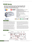
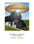
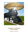
A
SIDET R
ED
K
C
INFRARED TRAIN
DETECTOR WITH TIMER
(ITD-TR)
The Infrared Train Detector with Timer (ITD-TR) uses an Infrared (IR) sensor to detect a
train and then turn on a relay for an adjustable period of time.
By connecting track power through the relay on the ITD-TR you can stop a train for an
adjustable period of time once it has been detected. Some applications could be to
automatically stop a train at a station for a set period of time or to extend the time a train
spends hidden in a tunnel to give the impression of distance. Applications do not have to
be limited to just controlling trains. The ITD-TR could be used to activate a sound
module or some lights embedded in the scenery as a train passes by.
The ITD-TR is not designed to stop trains operated by DCC.
What you should have
1 x Sidetracked Electronics Infrared Train Detector with Timer (ITD-TR).
1 x 3mm red LED.
1 x User manual.
About this manual
Text written in ITALICS in this manual represents text as it is written on the ITD-TR.
Operation
The operation of the ITD-TR is very simple. When a train is detected the relay on the
ITD-TR is activated for a period of time determined by the timer control. If an indicator
LED is connected then it will be illuminated while the relay is active. Once the timer has
elapsed the relay and LED will be turned off and cannot be reactivated until the IR
sensor has been clear for two seconds.
If you need to turn the relay off before the timer has elapsed you can connect a push
button switch to the ITD-TR. Whenever the button is pushed while the timer is active,
the timer will be reset and the relay and LED will be switched off. The timer cannot be
reactivated until the button has been released and the IR sensor has been clear for two
seconds.
If the push button is pressed when a train is first detected then the timer will not be
activated at all. The timer can only be reactivated once the button has been released and
the IR sensor has been clear for two seconds.
The reason for the two second delay is that as a train passes over the IR sensor it is
possible for the ITD-TR to momentarily stop detecting the train. This could be because
of an irregular surface under the train causing the IR beam not to reflect properly or the
gaps between the carriages where there maybe no reflective surface at all. By having the
delay it compensates for the time the train may go undetected an ensures that the ITD-TR
functions correctly.
1
Installing the ITD-TR
There is two parts to each infrared (IR) sensor on the ITD-TR, a transmitter and a
receiver. When mounting the ITD-TR make sure the two components of the IR sensor
are pointing directly up or slightly bent in towards each other. The train acts like a
reflector when it passes over the IR sensor so if they are pointing away from each other
the train may go undetected.
Underside of train
Underside of train
Underside of train
ITD-TR
ITD-TR
ITD-TR
CORRECT
CORRECT
INCORRECT
It is recommended that the ITD-TR is mounted under your layout and the IR sensor
pushed up between the sleepers in the centre of your track. Drill two 4.0mm (5/32 inch)
holes with 5mm between their centres or make a 4.0mm x 9.0mm slot, being careful not
to damage the track. Screw the IR sensor in place, adding a spacer if necessary so that the
top of the IR sensor sits level with the top of your ballast or sleepers.
IMPORTANT: Make sure nothing covers the top of the IR sensor and that the rubber
tubing that surrounds one of the sensors stays intact once the ITD-TR has been installed.
Do not apply any heat to the rubber tubing as it my distort and affect the operation of the
sensor.
5mm
Track
Roadbed
Baseboard
30mm
4mm
hole
50mm
Spacer
2
Isolating Tracks
In order for the ITD-TR to stop a train without disrupting train operation on other parts
of your layout you will have to isolate a section of track for the train to stop in.
Once you have determined the location of the ITD-TR you will have to cut one rail of the
track in two locations.
The first cut goes in the rail approaching the ITD-TR and must be in a position that
allows sufficient room between the cut and the IR sensor to fit your longest train. This
ensures that trains will always stop regardless of whether the locomotive is pulling or
pushing the train.
Before making the second cut it is important to note that a train may not stop
immediately the IR sensor detects it. Depending on the speed that the train is travelling
when power is cut from the track determines how far the front of the train will run past
the IR sensor. With this in mind make the second cut just past the IR sensor allowing
enough room for the train to stop.
Allow enough room for your longest train between isolation cut and the
IR sensor.
Allow enough room
for train to stop.
Train Direction
IR SENSOR
Isolation cut
Isolation cut
To 9V
power supply
To train
controller
Momentary on push
button switch
Timer control
Wiring Track Power
From your train controller wire from one terminal directly to the rail which has not been
cut. The second terminal on the controller goes to two places. The first wire goes directly
to the cut rail outside the isolated section of track. The second wire goes to the isolated
section of track via the NC (normally closed) and C (common) terminals on the ITD-TR.
Wiring a Switch
Wiring in a momentary on push button switch allows you to turn the relay off before the
timer has elapsed. The two pins on the switch need to wired to the GND and IP1
terminals on the ITD-TR.
Wiring Power to the ITD-TR
You require a 9V DC power supply capable of supplying a maximum of 50mA for each
ITD-TR unit you have connected to it. Ensure that you connect the 9V (+ positive) wire
from your power supply to the +9V terminal on your ITD-TR and the ground
(- negative) wire from your power supply to the GND terminal.
3
Wiring an Indicator LED
LEDs have to be connected in a certain way in
order for them to work. They are polarised,
meaning they have a positive (anode) and a
negative (cathode) pin. The cathode pin is easily
identified as it is either the shorter of the two
Cathode
leads and/or its marked by a flat spot on the
LED
body of the LED. A LED can be mounted
Anode
remotely and then wired to the ITD-TR to
indicate when the relay is active. To connect an indicator LED, wire the cathode of the
LED to the OP2/LD- terminal and the anode to the LD+ terminal. No resistor is required.
Whenever the relay on the ITD-TR is activated the LED will illuminate as well.
A 3mm red LED is provided.
Interfacing the ITD-TR to other Equipment
You can interface the ITD-TR to other equipment either via the relay or output terminals
OP1 and OP2/LD-. The relay has three terminals, Common (C), Normally Open (NO)
and Normally Closed (NC). When the timer is off then the Common (C) is connected to
the Normally Closed (NC) terminal. When the timer is active the Common (C) is
connected to the Normally Open (NO) terminal.
Output terminals OP1 and OP2/LD- are open collector outputs. Both outputs will be
active (pulled low) while the timer is active.
Adjusting Timer Delay
The ITD-TR has a timer which controls the length of time the relay is activated for once
a train has been detected. The timer can be adjusted for a delay from 1 second to just
over 5 minutes. By winding the timer control in a clockwise direction you increase the
time delay and by winding it in an anti-clockwise direction you decrease it.
Controlling Train Speed
The ITD-TR does not control the speed of the train, this is done by an external DC train
speed controller connected to the relay contacts on the ITR-TR. The ITD-TR simply
turns the power to the track on and off .
The ITD-TR is not designed to stop trains operated by DCC.
Specifications
Dimensions:
Supply Voltage:
Supply Current:
Maximum Relay (Track) Voltage:
Maximum Relay (Track) Current:
65mm (width) x 32mm (depth) x 50mm (height)
9V DC
50mA
30V
2A
Sidetracked Electronics
PO Box 7085, Safety Bay Western Australia, 6169
Phone: +61 8 9528 5344
Email: [email protected]
Website: www.sidetracked-e.com
© Copyright
V0R00
4