1
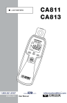
PHASE ROTATION METER (NON-CONTACT) ENGLISH User Manual 6610 Statement of Compliance Chauvin Arnoux®, Inc. d.b.a. AEMC® Instruments certifies that this instrument has been calibrated using standards and instruments traceable to international standards. We guarantee that at the time of shipping your instrument has met its published specifications. The recommended verification interval for this instrument is 12 months and begins on the date of receipt by the customer. For verification, please use our calibration services. Refer to our repair and calibration section at www.aemc.com. Serial #: _______________________________ Catalog #:2121.12 Model #: 6610 Please fill in the appropriate date as indicated: Date Received: __________________________ Date Calibration Due: _____________________ Chauvin Arnoux®, Inc. d.b.a AEMC® Instruments www.aemc.com Table of Contents 1.INTRODUCTION................................................................................ 2 1.1 International Electrical Symbols.................................................3 1.2 Definition of Measurement Categories......................................3 1.3 Receiving Your Shipment...........................................................3 1.4 Ordering Information..................................................................4 1.4.1 Accessories and Replacement Parts.............................4 2. PRODUCT FEATURES....................................................................... 5 2.1 Description.................................................................................5 2.2 Features.....................................................................................5 2.3 Applications...............................................................................5 2.4 Control Features........................................................................6 3.OPERATION..................................................................................... 7 3.1 Making Measurements..............................................................7 3.2 Live Wire Check.........................................................................9 4.MAINTENANCE.............................................................................. 10 4.1 Replacing the Battery..............................................................10 4.2 Cleaning...................................................................................10 5.SPECIFICATIONS........................................................................... 11 Repair and Calibration............................................................................12 Technical and Sales Assistance.............................................................12 Limited Warranty....................................................................................13 Warranty Repairs....................................................................................13 Phase Rotation Meter Model 6610 1 CHAPTER 1 INTRODUCTION Warning These safety warnings are provided to ensure the safety of personnel and proper operation of the instrument. • To ensure safe operation and usage of this instrument, follow instructions in this manual. Failure to observe Warnings may result in SEVERE injury or death. • It is recommended for use in distribution level and fixed installations, as well as lesser installations, and not for primary supply lines, overhead lines and cable systems. • Do not exceed the maximum overload limits per function (see specifications) nor the limits marked on the instrument itself. Never apply more than 600V CAT IV or 1000V CAT III between the test lead and ground/earth. • Inspect the meter and test leads before each use. Do not use any damaged parts. • Never ground yourself when taking measurements. Do not touch exposed circuit elements. • Do not operate the tester in an explosive atmosphere. • Exercise extreme caution when measuring voltage >50V and current >10mA. • Never open the battery compartment cover while measuring. • Do not operate in a manner not specified or the instrument’s protection may be impaired. 2 Phase Rotation Meter Model 6610 1.1 International Electrical Symbols This symbol signifies that the instrument is protected by double or reinforced insulation. CAUTION - Risk of Danger! Indicates a WARNING and that the operator must refer to the user manual for instructions before operating the instrument in all cases where this symbol is marked. Important instructions to read and understand completely. Important information to acknowledge. Risk of electric shock. The voltage at the parts marked with this symbol may be dangerous. AC Alternating current Compliance with the Low Voltage & Electromagnetic Compatibility European directives (73/23/CEE & 89/336/CEE) In the European Union, this product is subject to a separate collection system for recycling electrical and electronic components In accordance with directive WEEE 2002/96/EC 1.2 Definition of Measurement Categories CAT I: For measurements on circuits not directly connected to the AC supply wall outlet such as protected secondaries, signal level, and limited energy circuits. CAT II: For measurements performed on circuits directly connected to the electrical distribution system. Examples are measurements on household appliances or portable tools. CAT III:For measurements performed in the building installation at the distribution level such as on hardwired equipment in fixed installation and circuit breakers. CAT IV:For measurements performed at the primary electrical supply (<1000V) such as on primary overcurrent protection devices, ripple control units, or meters. 1.3 Receiving Your Shipment Upon receiving your shipment, make sure that the contents are consistent with the packing list. Notify your distributor of any missing items. If the equipment appears to be damaged, file a claim immediately with the carrier and notify your distributor at once, giving a detailed description of any damage. Save the damaged packing container to substantiate your claim. Phase Rotation Meter Model 6610 3 1.4 Ordering Information Phase Rotation Meter Model 6610 (Non-Contact)..........Cat. #2121.12 Includes meter with attached test leads (black, red and blue) with large alligator clips, soft carrying case, one 9V battery and user manual. 1.4.1 Accessories and Replacement Parts Case - Replacement soft carrying case...............................Cat. #5000.41 Order Accessories and Replacement Parts Directly Online Check our Storefront at www.aemc.com for availability 4 Phase Rotation Meter Model 6610 CHAPTER 2 PRODUCT FEATURES 2.1Description The Phase Rotation Meter Model 6610 is an essential tool for any installation, inspection and maintenance facility. The Model 6610 is designed to identify phase rotation on 3-phase systems and identify live and open/de-energized phases. The phase order is determined as soon as the leads are connected. Presence of live wires and phase sequence are informed by LED indication and a buzzer as soon as detection has occurred. The Model 6610 is ideal for installing rotating machinery or motors, and for checking generator output. 2.2Features • • • • • • • • • • Non-contact (no metal contact points) Operating voltage: 75 to 1000VAC Frequency range: 45 to 65Hz Phase rotation LED indicators (ABC or BAC) Bright LED indication Live or Open Phase (A, B, C) Includes three attached color-coded test leads with alligator clips for easy connection to the device under test Clipping the non-electrical contact alligator sensor clips onto the insulation of the phase conductor promotes operator safety during measurement Low battery indicator Back cover includes a magnet feature that can mount the instrument onto an AC distribution panel for easy measurement EN61010-1; 1000V CAT III; 600V CAT IV 2.3Applications • • • Verify proper phase wiring Detect open or de-energized phases Determine correct wiring for proper rotation on motors, pumps, etc. Phase Rotation Meter Model 6610 5 2.4 Control Features CAT IV 600V CAT III 1000V 45-65Hz 75-1000VAC BLACK RED BLUE A /L1 B/L2 C/L3 1 2 3 BRIGHTER ON/OFF PHASE ROTATION METER MODEL 6610 4 5 BAC ABC Figure 2-1 1. Live/Open LED phase indicators 2. ON/OFF power button 3. LED brightness button 4. Phase sequence LEDs 5. Battery LED (flashes if low) 6 Phase Rotation Meter Model 6610 CHAPTER 3 OPERATION 3.1 Making Measurements Before proceeding with a measurement, read the safety notes on page 2. 1. Press the power button to turn on the instrument. All of the LEDs will flash during the first 2 seconds. Only the Green Battery OK LED will stay on at the completion of the self test. Do not use the instrument if any of the LEDs do not function properly. 2. Position the clamp on each conductor to be measured so that the point of the triangle mark “▼” on each jaw of the measurement clip is centered on each measured conductor. Figure 4-1 Phase Rotation Meter Model 6610 7 3. Connect three clips as shown: Black L1, to Phase-A. Red L2, to Phase-B. Blue L3, to Phase-C. BLACK A/L1 RED B/L2 BLUE C/L3 Figure 4-2 4. Measure a live insulated conductor carrying 75VAC or more first to confirm each live LED lights up. 5. The presence of live wires and phase sequence are confirmed by LED indication and buzzer as soon as detection is completed. 6. A, B and C LEDs are always lit up when the instrument detects a live phase. 7. ABC Green LED ON = correct phase sequence BAC Red LED ON = incorrect phase sequence 8. The maximum cable diameter that the measurement clips can connect to is 1.18 inches (30mm). 8 Phase Rotation Meter Model 6610 3.2 Live Wire Check STATE INDICATION Live Phase with A, B, C LEDs are ON. Missing Ground/Earth line LED does not light up for missing Ground/Earth line. Ground/Earth line (Delta connection) Phase with flashing LED = Ground/Earth phase. Positive phase Green ABC LED ON = The circuit under test is phased correctly. The buzzer sounds intermittently. Reversed phase Red BAC LED ON = The circuit under test is reverse phased. The buzzer sounds continuously. Detection Indicators A, B, C LEDs ON = Indicates a live phase. LEDs OFF = Indicates an open or de-energized phase. Green ABC LED ON = Correct phase sequence. Red BAC LED ON = Incorrect phase sequence. Phase Rotation Meter Model 6610 9 CHAPTER 4 MAINTENANCE Use only factory specified replacement parts. AEMC® will not be held responsible for any accident, incident, or malfunction following a repair done other than by its service center or by an approved repair center. 4.1 Replacing the Battery Disconnect the instrument from any electrical source. When low battery LED flashes, replace with new batteries. To replace the battery, perform the following steps: • Remove all clips from any conductor and make sure the instrument is OFF. • Loosen the screw that secures the battery compartment cover and open cover. • Replace the battery with a new 9V alkaline battery. Ensure battery is inserted with the correct polarity. • Install the battery compartment cover and tighten the screw. 4.2Cleaning Disconnect the instrument from any electrical source 10 • If the case needs cleaning, do not use any alcohol or oil based cleaners. Preferably use soapy water with a damp cloth or sponge. • Dry immediately after cleaning. Avoid water penetration into the electronic module. Phase Rotation Meter Model 6610 CHAPTER 5 SPECIFICATIONS ELECTRICAL Measurement Principle Operating Voltage Frequency Range Auto-Off Power Source Low Battery Warning Current Consumption MECHANICAL Dimensions Weight Cable Length ENVIRONMENTAL Operating Temperature Storage Temperature Humidity SAFETY Static induction 75 to 1000VAC 45 to 65Hz 5 minutes after power on if not in use 1 x 9V alkaline battery ≤ 7V ± 0.2V 20mA 5.0 x 2.8 x 1.8" (128 x 72 x 46mm) 0.82 lbs (375g) including battery 2.5 ft (800mm) approx. Safety Rating CE Mark 14° to 122°F (-10°C to 50°C) -4° to 140°F (-20° to 60°C) 80% RH IEC61010-1; 1000V CAT III; 600V CAT IV; EN61326-1 Yes Specifications are subject to change without notice Phase Rotation Meter Model 6610 11 Repair and Calibration To ensure that your instrument meets factory specifications, we recommend that it be scheduled back to our factory Service Center at one-year intervals for recalibration, or as required by other standards or internal procedures. For instrument repair and calibration: You must contact our Service Center for a Customer Service Authorization Number (CSA#). This will ensure that when your instrument arrives, it will be tracked and processed promptly. Please write the CSA# on the outside of the shipping container. If the instrument is returned for calibration, we need to know if you want a standard calibration, or a calibration traceable to N.I.S.T. (Includes calibration certificate plus recorded calibration data). Ship To: Chauvin Arnoux®, Inc. d.b.a. AEMC® Instruments 15 Faraday Drive Dover, NH 03820 USA Phone:(800) 945-2362 (Ext. 360) (603) 749-6434 (Ext. 360) Fax: (603) 742-2346 or (603) 749-6309 E-mail:[email protected] (Or contact your authorized distributor) Costs for repair, standard calibration, and calibration traceable to N.I.S.T. are available. NOTE: You must obtain a CSA# before returning any instrument. Technical and Sales Assistance If you are experiencing any technical problems, or require any assistance with the proper operation or application of your instrument, please call, mail, fax or e-mail our technical support team: Chauvin Arnoux®, Inc. d.b.a. AEMC® Instruments 200 Foxborough Boulevard Foxborough, MA 02035 USA Phone:(800) 343-1391 (508) 698-2115 Fax: (508) 698-2118 E-mail:[email protected] www.aemc.com NOTE: Do not ship Instruments to our Foxborough, MA address. 12 Phase Rotation Meter Model 6610 Limited Warranty The Phase Rotation Meter Model 6610 is warranted to the owner for a period of one year from the date of original purchase against defects in manufacture. This limited warranty is given by AEMC® Instruments, not by the distributor from whom it was purchased. This warranty is void if the unit has been tampered with, abused or if the defect is related to service not performed by AEMC® Instruments. For full and detailed warranty coverage, please read the Warranty Coverage Information, which is attached to the Warranty Registration Card (if enclosed) or is available at www.aemc.com. Please keep the Warranty Coverage Information with your records. What AEMC® Instruments will do: If a malfunction occurs within the one-year period, you may return the instrument to us for repair, provided we have your warranty registration information on file or a proof of purchase. AEMC® Instruments will, at its option, repair or replace the faulty material. REGISTER ONLINE AT: www.aemc.com Warranty Repairs What you must do to return an Instrument for Warranty Repair: First, request a Customer Service Authorization Number (CSA#) by phone or by fax from our Service Department (see address below), then return the instrument along with the signed CSA Form. Please write the CSA# on the outside of the shipping container. Return the instrument, postage or shipment pre-paid to: Ship To: Chauvin Arnoux®, Inc. d.b.a. AEMC® Instruments 15 Faraday Drive • Dover, NH 03820 USA Phone:(800) 945-2362 (Ext. 360) (603) 749-6434 (Ext. 360) Fax: (603) 742-2346 or (603) 749-6309 E-mail:[email protected] Caution: To protect yourself against in-transit loss, we recommend you insure your returned material. NOTE: You must obtain a CSA# before returning any instrument. 04/12 99-MAN 100375 v1 Chauvin Arnoux®, Inc. d.b.a. AEMC® Instruments 15 Faraday Drive • Dover, NH 03820 USA • Phone: (603) 749-6434 • Fax: (603) 742-2346 www.aemc.com