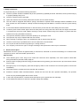
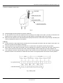
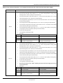
1
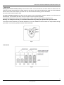
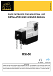
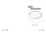
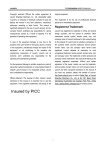
DOOR OPERATOR FOR INDUSTRIAL USE
INSTALLATION AND HANDLING MANUAL
RSI-60/RSI-120
WARNING
Please read the manual carefully before installation and use. The installation of your new door opener must
be carried out by a technically qualified or licensed person. Attempting to install or repair the door opener
without suitable technical qualification may result in severe personal injury, death and / or property damage.
RSI-60/RSI-120 DOOR OPERATOR FOR INDUSTRIAL USE
OUTLINE
1. Safety instructions ................................................................................................................................ 3
2. General description ................................................................................................................................ 3
3. Main technical parameters ..................................................................................................................... 4
4. Main structure ...................................................................................................................................... 4
5. Installation ............................................................................................................................................ 5
6. Wiring ................................................................................................................................................... 6
7. Adjustment ........................................................................................................................................... 10
8. Maintenance ........................................................................................................................................ 12
9. Troubleshooting ................................................................................................................................... 13
10. Packing list .......................................................................................................................................... 13
2
www.ryterna.eu
RSI-60/RSI-120 DOOR OPERATOR FOR INDUSTRIAL USE
1. Safety instructions
It is important that you read all the following instruction:
The door operator should be installed and put into operation by qualified personnel. Otherwise, serious personal injury
or property damage may occur.
The door operator must be grounded.
Open and close the door manually, make sure the door can be moved smoothly.
The door must be equipped with balance springs, otherwise the operator will be damaged. Before installation of the
door operator, the door should be carefully checked for being kept well balance. The door must be in good working
order.
It is recommended to install limit devices on door tracks to prevent the door from sliding out of the tracks.
Locate any fixed control: within sight of door but away from all moving parts of the door and at a height of more than
1.4m above the ground to avoid children reaching it. Keep remote controls away from children, to prevent the door
operator from being activated involuntarily.
The operator should be switched off before repairing it or opening its cover.
The operator may only be repaired with the door closed.
When opening or closing the door, do not attempt to walk or drive through the door.
The door should only be operated when it can be observed to avoid accidents.
Do not pull the hand chain during opening or closing the door.
Our company reserves the right to change the design and specification without prior notification.
2. General description
RSI-60/RSI-120 door operator is applied widely to storehouse, industrial or commercial buildings. It is featured with
compact structure, safe and reliable performance.
Main function
Three buttons (open, close, stop) on the control box control the door separately. The control system is fitted with
wiring terminals for photocell, safety edge etc.
Remote control: hopping code technology prevents thieves from guessing your remote code. Up to 25 remote controls
may be used.
Emergency stop: In an emergency, press the emergency switch on the control box can cut off the power of control unit
immediately.
Auto brake system: it makes the motor stop fast and accurately.
Rotate the release handle 180°anticlockwise, release the door from the door operator immediately. The operator
motor may only be disengaged with the door closed.
In the event of power failure, a release hand chain allows you to operate the door manually.
It has double limit switches to ensure the operator safety and reliability.
3
www.ryterna.eu
RSI-60/RSI-120 DOOR OPERATOR FOR INDUSTRIAL USE
3. Main technical parameters
Model
Max. door area
RSI-60
Up to 35 m
RSI-120
2
Up to 45 m
2
Max. continues working
S3 = 30%
S3 = 30%
Power supply, frequency
220 V / 50 Hz
380 V / 50 Hz
Max. door height
Output shaft aperture
Depends on door construction, at 20 rpm of the output shaft
Ø25,4 mm
Ø25,4 mm
550 W
750 W
3А
3А
Max. output torque
60 N m
120 N m
Output shaft rotation speed
24 rpm
24 rpm
1400 rpm
1400 rpm
59:1
59:1
Motor power
Rated current consumption
Motor rotation speed
Ratio
Chain length
12 m
12 m
-20°С ~ +60°С
-20°С ~ +60°С
Thermal protection
120°С
120°С
Weight
22 kg
22 kg
447mm х 295mm х 124mm
447mm х 295mm х 124 mm
Operating temperature
Dimensions
4. Main structure
Fig.1
4
www.ryterna.eu
RSI-60/RSI-120 DOOR OPERATOR FOR INDUSTRIAL USE
5. Installation
Before installing, make sure the door is in good working order. We advise to install the operator as follow see “direct
installation” section or “indirect installation” section.
1) Direct installation (standard accessories see page 13 “Packing list”)
Fig.2
Screw the wall bracket (L-shaped iron fitting) onto the wall with expansion bolt. You may install the wall bracket to left
side or right side of operator.
Slot the 1st spacer ring onto the door shaft.
Slot the door operator onto the door shaft (ensure correct position of the key) and screw onto the wall bracket.
Slot the 2nd spacer ring onto the door shaft and push against the door operator, make sure the chain hangs vertically.
Push the 1st spacer ring against the door operator and fix both rings.
5
www.ryterna.eu
RSI-60/RSI-120 DOOR OPERATOR FOR INDUSTRIAL USE
2) Indirect installation (chain drive)
Fig.3
Install the bigger sprocket wheel onto the door shaft end.
Fix the bracket on the wall with expansion bolts according to the length of the chain. (In order to install the door
operator firmly, we advise you to fix two pieces of wall brackets on left and right sides of the operator.
Attach the door operator on the brackets with bolts (M10) and ensure the hand chain hangs vertically. Thread up the
chain by adjusting the position of the operator.
6. Wiring
Locate control box: within sight of door but away from all moving parts of the door and at a height of more than 1.4m
above the ground to avoid children reaching it.
Connect ground wire from operator to terminal ‘E’ on control board. The operator must be well grounded.
Wires within the cable shall be protected so that no damage can result from contact with any rough, sharp part. In
order to protect electrical elements from water, waterproof adapter must be tightened by turning the plastic nut.
In an emergency, press the red emergency switch on the control box can cut off the power of control unit immediately.
Rotate the switch in arrow direction to make the switch return to its original position and resume normal operation.
Fig. 4 Wiring chart
6
www.ryterna.eu
RSI-60/RSI-120 DOOR OPERATOR FOR INDUSTRIAL USE
D2 D1 W V U N L3 L2 L1 E
X1
FU
TB
TA
X3
LED2
0V 24V 5V K G
BX1
LED1
REV
S
X2
IC2 1 2 3
ON
OFF
5V K G T S
T
ANT
X5
AN1
X4
CL CO OP PT CO DET
24V 0V 5V A
Fig.5 RSI-120 (380V) Control board diagram
7
www.ryterna.eu
RSI-60/RSI-120 DOOR OPERATOR FOR INDUSTRIAL USE
D2 D1 C C W V U
N L E
X1
X3
LED2
12V 5V K G
BX1
LED1
REV
X2
S
IC2 1 2 3
ON
OFF
5V K G T S
T
ANT
X5
AN1
X4
CL CO OP PT CO DET
0V 5V A
Fig.6 RSI-60 (220V) Control board diagram
8
www.ryterna.eu
RSI-60/RSI-120 DOOR OPERATOR FOR INDUSTRIAL USE
Before carry out any wiring work, it is essential to disconnect the control unit from the mains supply.
Type
Wiring
•
Connect power wires (AC220V) to ‘L’. Connect neutral wire to ‘N’, connect ground wire to ‘E’.
•
Connect motor wire (blue, brown, black) to ‘U’, ‘V’, ‘W’. If door running direction is wrong, please
exchange wires ‘V’ and ‘W’. (See Fig.6 X1 terminal block)
Connect close limit wire of limit switch (red) to ‘CL’, connect common wire (white) to ‘CO’, connect
•
open limit wire (green) to ‘OP’. (See Fig.6 X4 terminal block)
Connect signal wires of photocell (N.C.) to ‘PT’ and ‘CO’ and power wires to ‘12V’ and ‘S’. (See Fig.6
•
X3 and X4 terminal blocks)
Connect signal wires of safety edge switch (N.O.) to ‘PT’ and ‘CO’. (See Fig.6 X4 terminal block)
•
Connect external single button switch (N.O.) wires to ‘DET’ and ‘CO’, if connected, the short bridge
•
must be removed. (See Fig.6 X4 terminal block)
RSI-60
Connect external three button switch (N.O.) to ‘K’, ‘G’, ‘T’ and ‘S’. K-open (white), G-close (yellow),
•
T-stop (red), S-common wire (green). (See Fig.6 X3 terminal block)
•
D1-D2: Alarm lamp (AC220V)
•
LS-LS (yellow): opened signal output
•
DIP-switch
Position
ON
OFF
1
Auto-close enable
Auto-close disable
2
Inching close (auto-close disable)
Continuous close
3
Auto-close time delay: 7 seconds. Note:
Auto-close time delay: 20 seconds. Note:
DIP-switch 1 must be set ON.
DIP-switch 1 must be set ON
•
Connect phase wires (AC380V) to ‘L1’, ‘L2’, ‘L3’. Connect neutral wire to ‘N’, ground wire to ‘E’.
•
Connect motor wire (blue, brown, black) to ‘U’, ‘V’, ‘W’. If door running direction is wrong, please
exchange wires ‘U’ and ‘V’. (See Fig.5 X1 terminal block)
Connect close limit wire of limit switch (red) to ‘CL’, connect common wire (white) to ‘CO’, connect
•
open limit wire (green) to ‘OP’. (See Fig.5 X4 terminal block)
Connect signal wires of photocell (N.C.) to ‘PT’ and ‘CO’ and power wires to ‘24V’ and ‘0V’. Connect
•
signal wires of safety edge switch (N.O.) to ‘PT’ and ‘CO’. (See Fig.5 X3 and X4 terminal blocks)
Connect external single button switch (N.O.) wires to ‘DET’ and ‘CO’, if connected, the short bridge
•
must be removed. (See Fig.5 X4 terminal block)
Connect external three button switch (N.O.) to ‘K’, ‘G’, ‘T’ and ‘S’. K-open (white), G-close (yellow),
•
T-stop (red), S-common wire (green). (See Fig.5 X3 terminal block)
RSI-120
•
D1-D2: Alarm lamp (AC220V)
•
LS-LS (yellow): opened signal output.
•
Note: turn the power on, if the ‘LED2’ is flashing, disconnect from mains supply, then reverse
any two phase wires.
DIP-switch
•
Position
ON
OFF
1
Auto-close enable
Auto-close disable
2
Inching close (auto-close disable)
Continuous close
3
Auto-close time delay: 7 seconds. Note:
Auto-close time delay: 20 seconds. Note:
DIP-switch 1 must be set ON.
DIP-switch 1 must be set ON
9
www.ryterna.eu
RSI-60/RSI-120 DOOR OPERATOR FOR INDUSTRIAL USE
7. Adjustment
Adding extra remote controls (Learn): Press the button ‘AN1’ on the control board, the ‘LED2’ will be on and then turn off.
Press any remote control button, the ‘LED2’ will be on and then turn off. Press the same button again, the ‘LED2’ will flash
about 4 seconds at 1/2Hz frequency and then turn off, this indicates the learning process is finished.
Up to 25 remote controls may be used.
To erase all remoter controls: press and hold ‘AN1’ button on the control board, release the button once ‘LED2’ turns off
automatically. This indicates that all the remote controls have been erased completely.
The remote control works in three-channel mode, (button 1-open, button 2-close, button 3-stop) See Fig.7.
Warning: For safety and security, we recommend that the factory setting be replaced with a personal code.
The remote control came with your operator depends on your order. Additional remote controls can be purchased through
your dealer. If you have any problem, please contact the dealer.
Fig. 7
Limit switch
Fig. 8
10
www.ryterna.eu
RSI-60/RSI-120 DOOR OPERATOR FOR INDUSTRIAL USE
Rough adjusting
•
Check that the operator has firmly installed, open the door to desired position and observe the rotating direction of
green limit cams during opening. Loose the screws of green limit cams, then turn three cams in the same direction
until the limit switches click (the third green limit cam: opened signal output), finally tighten the screws with supplied
hexagonal wrench key.
•
Close the door to desired position and observe the rotating direction of red limit cams during closing. Loose the
screws of red limit cams, then turn two cams in the same direction (i.e. on the opposite direction of the green cam)
until the limit switches click, finally tighten the screws with supplied hexagonal wrench key.
Fine adjusting
•
After rough adjusting, you can open/close the door and observe whether the door has successfully reached the
desired position. If the door does not reach the desired position, fine adjusting could become necessary.
•
•
The adjusting bolts are used for fine adjustment, one turn is about 150mm of door movement.
The adjusting bolts in the green limit cams to make the door reach the desired open position, clockwise to open
less, anticlockwise to open more.
•
The adjusting bolts in the red limit cams to make the door reach the desired close position, clockwise to close less,
anticlockwise to close more.
Important note
•
Please operate the push button on the control box to adjust the limit switch, do not use remote control.
•
When the door reaches fully closed or opened position, ensure that the limit switches are active and the indicator
light on the control box turns off. If the light does not turn off, please readjust the limit switch.
Hand chain
You may select hand chain with handle or without handle according to your needs. The hand chain came with your
operator depends on your order.
Hand chain (without handle)
•
In case of power failure, you may open or close the door manually by operating the hand chain.
•
If the close indicator light on the control box flashes and the operator does not work by operating the control box
button, pull one side of hand chain lightly until a reset is carried out see Fig.10 (1), the close indicator light turns off,
and now the control box can be used.
Hand chain (with handle)
•
Pull the red handle, the door operator works in manual operation, you may open or close the door manually by
pulling the hand chain.
•
Pull the green handle, the door operator works in electrical operation, you may open or close the door electrically.
Note: If the close indicator light on the control box flashes, this means the door operator works in manual operation, please
pull the green handle till the indicator light on the control box turns off, now the door operator works in electrical operation.
11
www.ryterna.eu
RSI-60/RSI-120 DOOR OPERATOR FOR INDUSTRIAL USE
Fig. 9
Warning:
•
Tighten or loose the knob by rotating clockwise or anticlockwise until the hand chain can open or close the door
easily. See Fig.9
•
After using the hand chain for some time, the knob will become very hot. It is recommended to adjust it with a
spanner.
Note:
•
Use the hand chain only in case of power failure, NOT for normal use. Do not pull the chain during closing or
opening the door, otherwise, serious personal injury or property damage may occur.
•
It is important to ensure that the chain is not fitted twisted. If the chain is twisted, malfunctions may occur when the
hand chain is used. It is essential to screw the hand chain firmly in place as shown in Fig.10 (2).
Fig. 10
8. Maintenance
• Make sure the door is in good working order and that is correctly balanced.
•
The door operator should be checked and maintained by a qualified technician.
•
Keep operator clean at all times.
12
www.ryterna.eu
RSI-60/RSI-120 DOOR OPERATOR FOR INDUSTRIAL USE
9. Troubleshooting
Error
Cause for error
Remedies
The operator does not
work.
(1) Power is OFF.
(2) The door is obstructed.
(3) The wires become loose.
(4)The emergency switch was pressed.
(5) The door is too heavy.
(1) Make sure that power is ON.
(2) Remove obstructions.
(3) Fasten the wires.
(4) Rotate the emergency switch to ensure
that the button returns to its original position.
(5) Replace or readjust the balance springs.
The close indicator light on
the control box flashes and
the operator does not work
by pressing the control box
button or remote control.
An automatic reset is not carried out.
Pull one side of hand chain to carry out an
automatic reset.
The operator stops working
suddenly.
Thermal overload protection in motor is
active.
Allow the motor to cool down.
The door cannot be opened
or closed fully.
Wrong adjusting of limit switch.
Readjust the limit switch.
Remote control does not
work.
(1) Battery level may be low.
(2) Remote control is not suitable for
receiver. Wrong programming of
remote control coding.
(1) Replace the battery inside the remote
control.
(2)Erase remote controls and then
re-program the remote control.
10. Packing list
After receiving the product, you should make an unpack-inspection, in which you should check whether the product
was damaged. If you have any problem please contact our sales agent. You should find the following items in our
standard packing:
No.
Item
Quantity
1
Door operator
1
2
Wall bracket
1
3
Spacer ring and screw
2
4
Hexagonal wrench key
1
5
Control box
1
6
Remote control
2
7
Four cores wire 7m
1
8
Six cores wire 7m
1
9
Key
2
10
Bolt
4
11
Plain washer
4
12
User’s manual
1
13
www.ryterna.eu