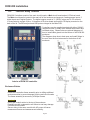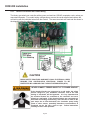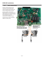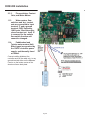
1
Installation Guide
DCM 200 series
Aquatic Water Quality Controller
ProMinent Fluid Controls
p/n 7500612
ϭϯϲ/ŶĚƵƐƚƌLJƌŝǀĞ⏐WŝƚƚƐďƵƌŐŚ͕W͕h^ϭϱϮϳϱͲϭϬϭϰDϮϬϬ/ŶƐƚĂůůĂƚŝŽŶ'ƵŝĚĞϬϮͬϭϮ
DCM 200 Installation
This page intentionally left blank
WĂŐĞϮ
DCM 200 Installation
Contents
1.
Overview
2.
Installation-Commissioning
2.1.
2.2.
2.2.1.
2.2.2.
2.3.
2.3.1.
2.3.2.
2.3.3.
2.3.4.
3.
Calibrations
3.1.
3.2.
4.
Safety
Mounting
Sample Connections
Sensor Installation
Wiring
120VAC Line Power and Feeder Wiring
Pulse Controlled Pumps
Flow switches, Contact Sets, and Water Meters
Sensors
Single Point Calibrations, 1 point or Standardization
Two Point Calibration
Password Security
4.1. Overview
4.2. Password Level Activities
4.3. Browser Passwords & Lockout
4.4. LCD Keypad Passwords
4.5. Passwords Reset
5.
Application Notes
5.1. Sensor Inputs & Control Outputs
5.2. Communications
5.2.1. Ethernet
5.2.2. USB Services
5.2.3. Data Logging
5.3. Control Configuration
5.3.1. Control Method
5.3.2. Frequency Controlled Pump Contacts 4 & 5
5.3.3. Special Control Responses
6.
Sensors
6.1. Compensation
6.2. Digital Input Sensor F
6.3. Contact Sets, Flow Switch F
6.4. Frequency Controlled Pumps
6.5. Technical: Pump Frequency-Stroke Controls
6.6. Relay & Frequency Controls Comparison
6.6.1. ON/OFF Controls
6.6.2. Frequency Controls
6.7. System Alarms & Indicating LEDs
WĂŐĞϯ
DCM 200 Installation
Contents
6.8. Units for Volumes & Temperatures
6.8.1. Metric – US Units Selection
6.8.2. Water Meter Volumes
6.8.3. Rate-to-Volume
6.8.4. Copy Volume to
6.8.5. Pump Volumes
6.8.6. mL/Pulse Meters
6.8.7. Temperatures
6.8.8. User Assigned Units
7.
Spare Parts
WĂŐĞϰ
DCM 200 Installation
1.
Overview
1.1. All ProMinent DCM 200 controllers have an integral web server with a CAT5 Ethernet
connection, ready to communicate with any internet ready computer, regardless of operating
system. This makes the ProMinent DCM 200 one of the easiest Aquatic controllers to allow you
to network and remotely monitor and control your pool and spa chemistry parameters.
1.2. DCM 200 controllers are optimized for aquatic water disinfection control applications. These
controllers use sensors to measure water quality and then control chemical feeders, UV systems,
recirculation pumps, heaters and more to maintain a safe and comfortable aquatic environment.
1.3. AC powered pumps and solenoids for ON-OFF, Time Modulated, and PID control may be mixed
with pulse signal, frequency controlled pumps.
2.
Installation-Commissioning
2.1. Safety
Before we talk about any installation or configuration, we need to talk about safety for you and your
co-workers, customers and swimmers. Please read and follow the caution and warning statements
below to familiarize yourself with the hazards associated with installation and operation of the
equipment covered in this manual.
Electrical Shock Hazards
Opening the controller enclosure with the controller
power turned on or plugged in, may expose the user
to AC line voltages on the controller circuit boards.
Ground the controller AC power to the ground screw
located on the bottom of the aluminum back plate.
A 120VAC plug and receptacle socket cables may
be provided with controllers installed in North
America. All must be grounded to the ground
screws located on the bottom of the aluminum back
plate. For personal safety, and moisture corrosion contamination prevention the enclosure cover should
always be installed and secured with all 4 screws when the DCM 200 is in operation.
Configuration Hazards
Fully understand the implications of the control setpoints,
interlocks and alarms that you select.
Aquatic Water
Treatment Controllers
operate chemical
feeders and other
devices that may pump
hazardous, corrosive
and toxic chemicals.
Injury and damage to equipment may result from improper
configuration.
Unplug or turn OFF the AC power to the controller if you have
any concerns regarding safety or incorrect controller operation,
and notify supervisory staff.
WĂŐĞϱ
DCM 200 Installation
Flow Switch Function
NEVER OVERRIDE A FLOW SWITCH
Uncontrolled feeding of concentrated chemicals can result in personal injury
or death. Sample and recirculation flow switches are critical safety devices
which prevent uncontrolled chemical feed. Follow Instructions Carefully.
Flow switches are provided with all ProMinent pool controllers and are an
integral safety device to prevent the uncontrolled feed of chemicals, which
could cause personal injury or death. This critical safety device must always
be available to protect the swimmers and others near the pool.
Flow switches should NEVER be bypassed, even temporarily.
The above precaution pertains to Input ‘F’ lockouts as well as the integral flow switch on input ‘E’. If
disabled or bypassed, the sensor would not be able to sense a hazardous situation and turn of the
chemical feed pumps to prevent uncontrolled chemical feed.
Test Flow Switch Function
If flow switch ‘float’ does not drop to the bottom and remain there
during no-flow, backwash, or very low flow conditions, the
controller cannot prevent the uncontrolled feed of chemicals,
which could cause personal injury or death.
Testing of the flow switch installation is essential to assure the
flow switch stops, remains stopped, and controller shows
“SensorFlow ALARM” within 20 seconds, whenever filter is in
backwash or circulation flow stops. If the flow switch does not fully
drop, plumbing corrections or the installation of additional
safeguards will be necessary to avoid uncontrolled chemical feed.
Chemical Feeders
NEVER CONNECT FEEDER DIRECTLY TO POWER SOURCE
If the chemical feeders are connected to a wall outlet, the safety
devices integral to your ProMinent controller, and to the safe
feeding of chemicals, will be bypassed. It is very important that
the chemical feeders be connected to the controller and never
directly to a wall outlet. If the chemical feeders are connected to a
wall outlet and feeding continuously, when the flow of water to the
pool stops due to filter backwash, the circulation pump losing
prime or other causes, potentially hazardous concentrations of
chemicals can be fed into a pool or spa. Follow Instructions
carefully to insure safe operation.
WĂŐĞϲ
DCM 200 Installation
ALWAYS USE ANTI-SYPHON DEVICES
Uncontrolled feeding of chemicals can result in injury or death.
Anti-Syphon devices must be installed on chemical feeders to prevent
uncontrolled feed of concentrated chemicals.
If a vacuum is created in the water circulation line and no anti-siphon
device is installed on the chemical feeders, potentially hazardous
concentrations of chemicals can be drawn into pool or spa. Always use
injection check valves and anti-siphon valves in the chemical feed lines to
prevent this situation from occurring.
Electrical Surges
ELECTRICAL SURGES CAN DAMAGE YOUR
CONTROLLER
Uncontrolled feeding of chemicals can result in injury or death.
A damaged controller could feed chemicals in an uncontrolled
manner.
If you suspect your ProMinent controller is not operating properly,
disconnect it from the chemical feeders until the problem has been
corrected.
ProMinent controllers, like all modern electronic devices can be damaged by severe electrical spikes and
surges, like lightning. Every effort has been made to harden your controller against such surges, but no
precautions are 100% effective. Additional surge protection can be installed at time of installation, but
even that is not a guarantee that surge damage will not occur. If surge damage occurs, chemicals could
be fed to your pool or spa, continuously with no safety controls. If you inspect your ProMinent controller
after a possibly damaging power surge (thunderstorm or power outage) and suspect the controller is not
operating properly, disconnect the chemical feeders at once, and contact your ProMinent dealer for
service.
Water disinfection
control involves
irritating, corrosive,
caustic, and potentially
toxic chemicals. Use
extreme caution and
comply with all national,
state and local
regulations and
recommendations for the
handling and storage of
these chemicals.
WĂŐĞϳ
DCM 200 Installation
2.2
Mounting
1.1.
1.2. Fully Assembled System on Acrylic Backpanel
1.3.
1.4. Overall System Mounting
•
•
•
Locate an area on a flat wall large enough to
accommodate the full size of the 22x22” system
panel with enough extra room to accommodate
flexible sample tubing. The controller is shipped
with a 3 ft. power cord already installed, for easy
connection to a close wall receptacle.
Alternatively, you may choose, or be required, to
install conduit into the bottom of the controller
enclosure. Refer to Section 4.4 for enclosure
opening sizes and locations.
Refer to dimensional drawings in appendix section
for location and spacing of pre-drilled mounting
holes, measure and mark these locations on the
wall.
Approximate weight of the assembled system with
water flowing may be in excess of 30 lbs., so take
care to choose adequately sized mounting hardware.
1.5. Individual Components
•
DCM 200 Controller Enclosure Mounting
Locate an area on a vertical wall where the
controller can me mounted at approximately eye
level and have enough clearance to allow the
DGMa modular sensor housing to be installed near
and below the controller. The location of the
sensor housing must have about 18” of clearance
above it to allow removal of the sensors, and about
12 inches below to access water sample petcock
and a sample cup.
NOTE: a common mistake made at installation, is
not allowing enough space above the sensor
housing to accommodate easy sensor maintenance.
WĂŐĞϴ
DCM 200 Installation
DCM 200 Controller Enclosure Mounting (continued)
•
•
•
•
•
Individual DCM 200 controllers are shipped with mounting bracket (4) and mounting screws (1) to
assist with wall mount installation.
Snap the bracket off the back of the enclosure by pressing the release clip (4) at the bottom, and slide
the enclosure off the bracket. The wall mounting bracket can then be used as a drilling template.
Mount the bracket on a vertical wall at approximately eye level, within 3ft. of the nearest 120VAC
power outlet. Alternatively, mount near a power disconnect, and wire the power directly to the
controller through electrical conduit. Refer to local and national electrical codes for wet locations.
Fasten enclosure securely to the bracket as shown, by hanging enclosure on the bracket, pushing the
enclosure against wall and lifting until the enclosure snaps securely to the bracket.
After controller is mounted, time is best used mounting the DGMa modular sensor housing to allow
sensors to equilibrate while the remainder of the installation, wiring and configuration is performed.
WĂŐĞϵ
DCM 200 Installation
2.2.1.
Sample Connections
Modular Sensor Housing (DGMa)
Mount white acrylic mounting plate within 60” of the DCM 200 controller, and allow at least 18”
clearance above the top of the mounting plate.
• Using the typical installation drawings on the following pages, connect sample tubing to the DGMa
modular sensor housing and the main recirculation lines, using the fittings supplied.
•
Note that the default mounting of the modular housing is to
flow from left to right.
•
•
•
•
•
If preferred, the modular housing is reversible by
removing the assembled modules from the black upper
snap clips.
First disconnect the spacer standoff brackets and pull
the module assembly to unsnap it from the upper clips.
Once it is loose, simply flip the assembled modules so
that the molded arrows on the modules are pointing
right to left,
Then reconnect it to the standoff brackets and remount
onto the backpanel.
Next, use the typical installation drawing below as a
guide, and connect the sample supply and return
tubing using the selection of fittings supplied.
NOTE: Sensor Sample should always be from downstream of the filter, but up stream of the heater
and any chemical injection. Discharge sample into the line returning to the pool or spa as close to
the pool as possible to get the most pressure drop. Using the pressure drop created by other
devices like heaters or UV system works best.
CAUTION: Never take the sensor sample from unfiltered water as this may introduce hair or other debris into the
flow switch or sample cell. Never return sample to the suction side of the recirculation pump as this will cause a
negative pressure environment (vacuum) for the sensors, which will cause non-warranty damage to the sensors,
and more importantly, will cause erroneous readings and poor disinfection control.
Typical Vacuum Filter Arrangement
WĂŐĞϭϬ
DCM 200 Installation
WĂŐĞϭϭ
DCM 200 Installation
2.2.2.
Sensor Installation
ORP sensor
pH sensor
SGT sensor
Aquatic Sensor Placement in
DGMa Modular Sensor Housing
•
•
•
•
•
•
Check that all fittings of the assembly have O-rings installed, and fittings are secure.
Adjust flow switch shaft so the top of the ring at the bottom of the shaft is at the 12.5 gph mark, and
tighten the compression nut to keep the shaft from leaking and secure the flow switch shaft in place.
When you are ready to open up the sample water valves, remove the protective caps from the pH and
ORP sensors, and clean both sensors with Isopropyl alcohol followed by a mild acid, using a soft
bristled toothbrush.
Open the supply and return valves fully to evacuate all the air from the modular sensor housing.
Once all air has been evacuated, reduce flow through the assembly to 10-12 GPH for optimum sensor
performance.
Allow sensors to equilibrate while you complete the wiring of the controller.
WĂŐĞϭϮ
DCM 200 Installation
2.3. Wiring
Before beginning controller wiring, be sure power has been removed, locked out and tagged as under
repair, before proceeding. Observe all national and local electrical codes during wiring and installation
to best assure your safety and the safety of the pool operations staff and swimmers.
Wiring Guidelines
1.6. AC Controller Power
Power the controller using a dedicated, separate breaker in the local lighting-distribution panel.
Do not route the controller AC power in common conduit with variable frequency pump drives.
1.7. AC Power to Solenoid Pumps, Valves & Solenoids
Controller ON/OFF relays switch and power the AC line to valves, solenoids and solenoid pumps. Ensure
that each valve & solenoid has a dedicated neutral cable between the controller and the valve or
solenoid. Do not share a common neutral to multiple valves or solenoids.
1.8. Fractional Horsepower Chemical Feed Pumps
CAUTION
Fractional horsepower chemical feed pumps cannot be directly powered by the
controller. Use the controller 120VAC control output to switch a motor start relay with a
120VAC coil for these type pumps or feeders.
The controller ON/OFF relays 1 through 3 are fused at 5 amps total which will power multiple solenoid
driven chemical feed pumps and solenoid coils, but not the larger fractional horsepower rotational motor
pumps. Fractional horsepower feed pumps (>1/8 HP) are commonly used in high pressure chemical
feed applications and for large volume Sodium Hypochlorite pumps.
Typically, the high motor inrush current requires a dedicated breaker and separate AC feed from the
controller AC power breaker.
1.9.
1.10.
Sensor Wiring
Analog sensors (pH, ORP, and Temperature), contact sets, water meters and flow switches may be
cabled in a common conduit without causing operational problems.
Do not mix AC Line, 120VAC wiring with any sensor or communications cable in a common conduit.
Grounded, metallic conduit is preferred in areas where variable frequency drives operate.
WĂŐĞϭϯ
DCM 200 Installation
There is not a Sensor transmitter (preamplifier) available for the DCM 200. Sensors, may be not be
extended past the maximum available length of coaxial SN6 cable, 33 feet (10 meters). For applications
where the distance from the controller to the sensors exceeds 33 feet, consult your ProMinent distributor
for options available to you.
Verify that the shields on water meters are also spliced if meter cables are extended.
Ground signal cable shields at one end only to the internal frame lower bottom grounding screw.
1.11.
Ethernet LAN Cabling
CAT5 LAN cabling is limited to a maximum of 300ft / 100m from controller to access hub.
Do not exceed this limit.
Controller Enclosure Wiring
If shipped with the controller pre-mounted to an acrylic back panel, the controller has already been
wired to the sensors you purchased with the controller. Unless requested otherwise, the controller
has also been equipped with a 120VAC power cord. Refer to sections below for proper wiring of
power, individual sensors and feeders.
To facilitate easier wiring connections, the enclosure lid can be “parked in the open position as shown
below.
1. Loosen enclosure lid’s captive screws.
2. Carefully pull lid straight out just a few inches to avoid unplugging ribbon cables and internal
connectors.
3. Raise lid straight up until tabs on the sides of the lid align with recessed parking slots on the
side of the rear enclosure section.
4. Push tabs into slots until they snap into place, supporting the lid in an upright orientation.
WĂŐĞϭϰ
DCM 200 Installation
1.12.
Controller Wiring Terminals
DCM 200 Controllers consist of two main circuit boards, a Main circuit board and an LCD driver board.
The Main circuit board is located in the rear half of the enclosure and supports 3 analog sensor inputs, 2
digital inputs and 5 digital Outputs. The digital outputs consist of 3, 120VAC relays and 2, DC contacts.
It is connected to a single 2 line x 16 character LCD driver board and backlit LCD display mounted on the
back of the lid. The Ethernet jack and USB port are integral to the Main PCB.
Controllers may be supplied prewired with either 120VAC
receptacle cords, or ready to be installed with conduit and
individual wiring. Shown below are pictorial diagrams of
how to install cable glands into the bottom of the DCM 200
enclosure.
The diagrams show how to best open and install fittings in
the rear, then the front entrances on the bottom of the
enclosure.
Interior of DCM 200 controller
Enclosure Entries
Caution 1:
Remove the controller frame assembly prior to drilling additional
enclosure entries to prevent damage to wiring and circuit boards.
The frame assembly is secured by 4 Phillips screws.
Caution 2:
Do not put conduit entries in the top of the enclosure.
Resulting conduit condensation and failure to seal may damage
controller circuit boards.
Sensor wiring in the same conduit with AC power will cause
measurement errors and measurement instability.
WĂŐĞϭϱ
DCM 200 Installation
2.3.1. 120VAC Line Power and Feeder Wiring
The factory pre-wired your controller with a power cord and two 120VAC receptacle cords, unless you
requested otherwise. For conduit wiring configurations, remove the cords supplied and replace the
cord wiring with the individual wires from the conduit. The same terminals are used and are shown in
the diagram below for reference.
CAUTION
BASIC SAFETY PRACTICES AND MOST LOCAL ELECTRICAL CODES
REQUIRE THIS CONTROLLER’S ELECTRICAL POWER TO BE
PROTECTED BY A GROUND FAULT CIRCUIT INTERRUPTER (GFCI).
NEVER CONNECT FEEDER DIRECTLY TO POWER SOURCE
If the chemical feeders are connected to a wall outlet, the safety
devices integral to your ProMinent controller, and to the safe
feeding of chemicals, will be bypassed. It is very important that
the chemical feeders be connected to the controller and never
directly to a wall outlet. If the chemical feeders are connected to a
wall outlet and feeding continuously, when the flow of water to the
pool stops due to filter backwash, the circulation pump losing
prime or other causes, potentially hazardous concentrations of
chemicals can be fed into a pool or spa. Follow Instructions
carefully to insure safe operation.
WĂŐĞϭϲ
DCM 200 Installation
2.3.2.
Pulse Controlled Pumps
Pulsed controlled pumps can be
connected to give more precise
control options like PID control and
use low voltage wiring to convey
pumping signals to the feeders.
These features are built into all DCM
200 controllers as a standard feature.
Use the diagram below for
connections to ProMinent pump
universal control cable and similar
cables for other pumps.
WĂŐĞϭϳ
DCM 200 Installation
2.3.3.
Flow switches, Contact
Sets, and Water Meters
1.13.
Water meters, flow
switches and ‘dry’ contact
sets are connected to input
terminal ‘F’ and a ground
terminal. 5VDC limited by
10Kȍ puts 1/2mA through a
closed contact set. Input ‘E’
is reserved for the sample
flow switch function and
cannot be changed.
1.14.
Paddlewheel and
Turbine water meters (HallEffect types) are powered by
the 12VDC controller power
supply, and thermally fused
at 100mA.
Connect cabling shields at the
controller ends of the cable only, to any
ground terminal either on the Measure
Card or on the bottom center of the
aluminum frame back plate.
WĂŐĞϭϴ
DCM 200 Installation
2.3.4.
Sensors
pH and ORP Sensor Wiring
DCM 200 controllers normally have the cables for the pH and ORP sensors pre-wired and marked on the cables for the
appropriate sensor. The SGT (Solution Ground+Temp) sensor and flow switch are also pre-wired at the factory. If
replacing these cables, connect the center pins on the coaxial cables to the positive [+] terminal and the metallic shield is
connected to negative [-]. A solution ground reference is required for proper operation. An SGT sensor has a solution
reference (Green or Black) and temperature sensor (White or Red). Even if the temperature sensor is not being used, the
solution reference must be connected to the ground terminal.
WĂŐĞϭϵ
DCM 200 Installation
3. Calibrations
3.1. Single Point Calibrations, One-Point or Standardization
The pH and Temperature inputs A and C, have single point (Offset only) calibrations.
Input B is the ORP input and should never need field calibration. Calibration of contact set inputs “E and
F” is blocked.
3.2. Two Point Calibration
Two point calibration is limited to pH sensors.
Sensor OFFSET is adjusted so the sensor value matches the user’s calibration value.
Sensor GAIN is adjusted so that the sensor value matches the user’s calibration value. This is the
measured response for each engineering unit, and normally does not change for pH and Temperature
sensors used in aquatic applications.
The value of a sensor = Measured Level (mV) x GAIN + OFFSET.
This value may be modified by sensor compensation.
Compensation (Temperature, Rate-Volume, Corrosion Rate…) is applied after GAIN & OFFSET.
During calibration, users have the option to Reset to Factory, which resets the sensor GAIN & OFFSET
to default values.
If the calibration OFFSET or GAIN is outside fault limits, users are offered the option to OVERRIDE.
OFFSET or GAIN outside of the fault limits (typically indicates a sensor, cabling or driver fault).
OVEWRRIDE consists of submitting or pressing enter an additional time.
Users also have the option to manually enter OFFSET and GAIN by selecting Sensor then Configure in
the Browser interface. See the DCM200 Browser Manual for more information.
WATER METER F:
When Input F is configured as a volume (flow) meter, the user calibration value is Volume/contact for
contact head meters and ‘K’ factor (Pulses per unit volume [gallon]) for turbine and paddlewheel meters.
Reset to Factory
Newly installed firmware & reconfigured water meters are Reset to Factory Default calibrations when
controller Power is first turned on after install.
User selected Reset to Factory loads the GAIN, OFFSET set from the following table.
Sensor Type
1.15.
n
p
ut
Factory
Gain
Factory
Offset
Fault
MAX
Fault
MIN
100
0
None
None
1
0
0
0
0.017
-1
7
0
OFFSET
NA
OFFSET
NA
OFFSET
OFFSET
Type
Calculated Value
Manual Entry
pH
pH
ORP
Temperature
Temp
WĂŐĞϮϬ
DCM 200 Installation
US units
Metric units
Zener
0.18
0.1
-459.4
-273
-430
-253
-590
-293
4. Password Security
4.1. Overview
DCM 200 controllers use 4 levels of password for controller access and to stamp the activity log:
Public, Operator, Configuration, and Administrator
Refer to Section 4.2 for default user IDs and passwords.
Passwords are defaulted OFF for keypad users and ON for Browser users.
Passwords cannot be turned OFF for Browser users.
There are 7 user assignable passwords which are distributed between Operators & those allowed to Configure.
Passwords are a maximum of 9 letters and numbers and are case sensitive. The controller blocks the use of
HTML delimiter characters by limiting password content to letters and numbers only.
The controller blocks duplicate passwords.
4.2. Password Level Activities
Password Level
Activities
Notes
Public
1 per DCM 200
Views current state and alarm log.
Cannot adjust or edit.
Operator
4 per DCM 200
Operator1-4
Calibrate sensors. Prime Pumps or
force them off.
Changes setpoints and feed rates.
Can view but not edit all controller
configure level settings
Configure controls, interlocks and
blocking.
Sets sensor compensation, feed
alarms & limits.
Sets Event Timers, blocking & cycle
days.
Zeroes water meters
All Operator Activities
Set IP address and network
parameters.
All Operator & Configure Activities
Configure
3 per DCM 200
Configure 5-7
Administrator
1 per DCM 200
WĂŐĞϮϭ
Password not required for keypad or
browser use. Browser access to controller
alarm log only.
Can edit own user ID & password.
Keypad users, password only editing.
Controller default user ID is Operator1 thru
Operator4 with default passwords 1..4.
Can edit own user ID & password.
Keypad users, password only editing.
Controller default user ID is Configure5 thru
Configure7 with default passwords 5..7.
Browser: Can define other users as
Operator or Configure
Cannot view other users passwords.
Can edit own password, default ‘AAAA’
Cannot edit ‘Admin’ user id
DCM 200 Installation
4.3. Browser Passwords & Lockout
After 5 unsuccessful attempts to log on, the controller locks out Ethernet and Keypad access
Locked out users will see an Alarmed status message in place of Password Incorrect .
Browser & modem resets at 7:00AM or when AC power OFF/ON.
Therefore, the maximum lockout time is 24 hours and the minimum is less than a minute.
This feature blocks scripting attacks on controllers and cannot be disabled.
There is no limit on the number of keypad password attempts.
Changing all passwords from their default values is strongly recommended for Ethernet connected controllers.
Passwords can be reset to the factory default by logging on as the Reset Pswrds user.
Refer to Browser Manual for more information.
4.4. LCD Keypad Passwords
Passwords are defaulted OFF for keypad users.
The System/Password menu item does not display unless System/Configure has turned passwords ON.
Once passwords are turned ON, only the administrator can access System/Configure to turn Passwords OFF
If passwords are ON, you are prompted with the required password level; Admin / Configure / Operate when
you attempt to execute a command which reconfigures the controller.
Passwords are not required to view the current state.
Default Passwords & User IDs
User Type
User ID
Operator
Operator1
Operator2
Operator3
Operator4
Default
Password
1
2
3
4
Configure
Configure5
Configure6
Configure7
5
6
7
admin
AAAA
Administrator
Keypad-LCD access cannot change User Type or ID.
NOTE: If you are going to use keypad passwords, your first action after turning passwords ON should be to
change the admin and all other passwords since leaving any password at it’s default value, bypasses
password protection.
WĂŐĞϮϮ
DCM 200 Installation
4.5. Passwords Reset
Contact ProMinent Technical Department, at (412) 787 – 2484, with the controller serial number to obtain a
reset password which resets all passwords to the factory defaults shown above.
Proof of controller ownership is understandably required.
ProMinent controllers have no backdoor or super user password.
If you forget the password, this is the only way to recover controller access.
5. Application Notes
5.1. Sensor Inputs & Control Outputs
The controller uses the letters ‘A’ thru ‘F’ to identify input sensors, like pH, ORP, and Temperature, Flow
Switch, Surge Tank Level, Recirculation water flow meter, and other Digital signals. The numbers 1 to 5
identify the three (3) AC power switching relays and two (2) DC outputs for enable, alarm or pump pulse
frequency use.
‘A’ to ‘C’ and ‘E’ to ‘F’ exist as terminal blocks where inputs are connected. Sensor input ‘D’ is ‘virtual’ and
used to calculate Ryznar’s and Langelier’s SI indexes.
Users can also change the default names of sensors, pumps and valves to more meaningful, site specific
names. For example, although you may name controller meter input “E” to “Flow Switch”, ‘E’ identifies
where the meter is connected and the letter “E” is used to represent the “Flow Switch” input in hardware
connections and data logging.
Most inputs may be used to control almost any output with some logical aquatic application exceptions.
Sensor A
I/O Point
Function
Fixed pH sensor input
Sensor B
Fixed ORP sensor input
Sensor C
Temperature
Phantom or
Virtual Sensor D
Sensor E
Phantom sensor inputs
have no physical
connection and are used
for control and logging.
Fixed digital input
Sensor F
Fixed digital input
Relays 1 to 3
AC Line powered outputs
ON/OFF controls
Relays 4 and 5
DC switching outputs
Pulsing or ON/OFF
controls
Notes
Support for all ProMinent pH sensors.
All controllers have one pH sensor input.
Support for all ProMinent ORP sensors.
All controllers have one ORP sensor input.
Support for the ProMinent SGT 10mV/K temperature sensor.
Thermal compensation for the ‘A’ pH sensor.
This is a calculated value for LSI/Ryznar’s scale and
corrosion indecies.
There are two digital inputs. Input E is always used as the
Sample flow switch.
Digital input ‘F’ can be configured as an additional flow
switch or interlock, remote enable/disable, float switch, or
square wave pulsing flow meter.
Controller powered outputs switch 120 VAC pumps, valves
& solenoids ON/OFF. Log time ON. Relays are N.O. only.
Relays 2-5 are SPDT for motorized valves requiring power
OPEN & power CLOSE if needed. Outputs can alarm on
runtime per actuation and per day.
DC Alarm Contacts, remote enable, or Variable speed pulse
output feeds. Presets for popular ProMinent and other pump
ml/stroke and maximum rates.
WĂŐĞϮϯ
DCM 200 Installation
5.2. Communications
5.3. Ethernet LAN TCP-IP:
The DCM 200 controller contains a 10 Base T, RJ45 Ethernet port with a Fixed IP address assigned by
the administrator. Additional parameters adjustable are Netmask, Gateway and Primary DNS. The
controller operates as an HTML micro-server for command & control using Microsoft Windows IE7 and
Mozilla’s Firefox internet browsers available on most computers.
Logged data is served as an XML file in response to an HTML request. This feature makes
configuration easy using common Ethernet network browsers already installed on most computers, and
easily supported by local IT departments.
5.4. USB Services
All DCM 200 controllers include a USB port which is used for unformatted datalogging extraction to a
USB “thumb drive”.
5.5. Data Logging
Each enabled input and output is logged by the controller as a user set interval from 1
to 1440 minutes.
The default rate for all data is 60 minutes with a 2400 sample log size. Range is 4 to 600
days. Default maximum is therefore ~40 days of information.
5.3. Control Configuration
5.3.1.
Control Method
Relays 1 to 5 ON/OFF Controls
The distance between the “Turn ON” and “Turn OFF” setpoints, sets the deadband (hysteresis) response
of an ON/OFF relay, controlled by sensors A,B andC. Not applicable to relays controlled by volume
meters or contact set F.
Method
Function
Examples
Rising Setpoint
[Feed Down]
ON: Sensor > Turn ON Setpoint
OFF: Sensor < Turn OFF Setpoint
Acid Feed
Falling Setpoint
[Feed Up]
ON: Sensor < Turn ON Setpoint
OFF: Sensor > Turn OFF Setpoint
Oxidant Feed
Caustic Feed
Between Setpoints
[Not normally used in pools
and spas]
ON: Sensor < Turn ON Setpoint
& Sensor > Turn OFF Setpoint
OFF: Sensor > Turn ON Setpoint
Sensor < Turn OFF Setpoint
Blocking Controls or
Level Controls
Event Rising
[Not normally used in
Aquatic applications]
Rising Setpoint Operates only during
Timed Events
Caustic Feed or
Dechlorination
Event Falling
Falling Setpoint
Operates only during Timed Events
Oxidant alternate setpoint
Event Between
[Not normally used in
Aquatic applications]
Between Setpoints
Operates only during Timed Events
Blocking – sequencing
controls.
WĂŐĞϮϰ
DCM 200 Installation
5.7. Frequency Controlled Pumps, Contacts 4 & 5
Sets the variable frequency control range for pumps controlled by sensors A..C.
Not applicable to pumps controlled by volume meters or contact set F.
Method
Function
Examples
Always
Frequency varies proportional to
sensor value when value between
Turn ON and Turn OFF setpoints.
Proportional acid or oxidant
controls.
Substitutes for more
expensive 4-20mA controlled
pumps. Can also select PID
control functions in addition
to strictly proportional
control.
During Events
Control active during events until
event volume pumped.
Periodic flocculent feed
during a timed feed event.
5.3.3. Special Control Responses
Multiple Types of Control For Standard Relays
Time Modulation: Relays 1-5
Application: Cycles a chemical feed pump ON/OFF, decreasing the ON time as the
controlling sensor approaches the Turn OFF setpoint.
Typically used for pH control, reducing acid feed rate as the Turn OFF setpoint is approached.
Use if you can’t use a variable pulse frequency controlled pump.
Setup: User selects a relay & selects Time Modulation in Special Control.
User sets Period in seconds, minimum 60 (recommended), Default is currently at 120 Seconds,
maximum is 600 seconds.
Operation:
Relay ON 100% of Time Period when Control is beyond Turn ON setpoint.
Relay ON time = [ (Control – Turn OFF Setpoint) / Deadband ] x Period
where Deadband = Turn ON – Turn OFF setpoints.
Relay is OFF when Control is beyond Turn OFF setpoint.
Example: Acid Pumps Turn ON = 7.52 pH and Turn OFF = 7.50 pH. Period = 60 seconds
At pH >= 7.520, Pump ON for 60 seconds in every 60 seconds [100% of Period]
At pH = 7.515, Pump ON for 45 seconds in every 60 seconds [75%]
At pH = 7.510, Pump ON for 30 seconds in every 60 seconds [50%]
At pH = 7.505, Pump ON for 15 seconds in every 60 seconds [25%]
At pH <= 7.500, Pump OFF [0%]
Notes:
Time Modulation control is not advisable when the system response time is faster
than 5x the Period. In the previous Example; If the measured pH moves from 7.52 to
7.50 in less than 300 seconds, Time Modulation may not hold pH more stable.
Process buffering, pump setting, feed point and system volume all affect the
response to chemical feed.
Time modulation works on both Rising or Falling Setpoints.
WĂŐĞϮϱ
DCM 200 Installation
PID Time Modulation: Relays 1-5
Application: Time Modulation applications where additional variable loading control is needed
like extremely variable bather loading.
Setup: User selects a relay & selects Special Control = PID Control
User sets Relay Period in seconds, as in Time Modulated control, minimum 60
(recommended), default= 120, maximum is 600 seconds.
User sets Kp Proportional factor for correction to deviation from setpoint.
User Sets Ki Integral factor for correction for loading.
User Sets Ki updated time for how often checks are made for loading correction.
User Sets Kd Differential factor for corrections due to quick sensor changes.
User Sets Kd updated time for how often checks are made for quick sensor changes
Operation:
See PID Appendix for detailed setup explanation.
6. Sensors
6.1. Compensation
Analog Sensors A..C
Type
Thermal
(pH)
Setup
Temperature sensor C.
Defaulted as OFF
(see note below)
Rate-to-Volume
Water meter F displays and
logs resulting volume.
User selected rate/minute
or rate/hour
LSI and Ryznar’s indices
Calculated
Notes
Applied to pH sensors.
Zero compensation at 7 pH.
Compensation adjusts sensor gain (slope)
+0.00467%/°C above 25°C & -0.0058%/°C below
25°C
pH thermal compensation can only be applied to
directly connected pH sensors and not to
4-20mA inputs which may represent pH.
Can be used to show turnover rate of main pool.
Used on Virtual input D
Note: pH thermal compensation is seldom used in pools and spas since the pH is typically
between 7 & 8 and the temperature fairly stable, so the effect of thermal compensation is limited to
the third decimal place.
6.2. Digital Input Sensor F
Switching from Contact Set to Water Meter clears the log on the switched input.
Type
Setup
Notes
Contact Head
User set volume/contact
Contact Head compensation turns ON software debouncing. Volume counts on contact closure.
Contact opening ignored. Not normally used in Pools
and Spas.
User set ‘K’ factor, pulses/unit
volume
Counts pulse on falling edge, 400Hz max.
Ignores rising edge. Typical pool and spa circulation
flow meter sensors. (must be 12VDC powered
square wave sensors)
[not typical in
Aquatic
applications]
Turbine or
Paddlewheel
WĂŐĞϮϲ
DCM 200 Installation
6.3. Contact Set, Flow Switch F
Switching from Water Meter to Contact Set clears log.
Type
Setup
Notes
Contact Set
User selects Contact Set
Contact sets are ON when closed and OFF when
open. ON time is logged.
Contact sets used for interlocking, prevent relays
from turning ON when contact set is OFF, or open.
[typical Aquatic uses
are sensor flow
switch, main
recirculation flow
switch, auto fill
switch, or low
chemical level alarm]
Contact sets may be configured as ‘inverted’ to act
and display as ON when they are OFF.
6.4. Frequency Controlled Pumps
Feed Rate Setting
The controller knows the pump’s mL/stroke and maximum stroke rate (Maximum SPM), based on the
ProMinent pump model entered, or the values you entered for ‘Other’.
Once you select the pump feed method or control mode, the controller sets the optimum Pump Speed.
Modes
User Sets
Sensor
Controlled
TurnOFF :
pH or ORP setpoint
pH
100%ON :
pH or ORP setpoint
ORP
Proportional control.
Base
Feed
Feed
Events
Timed
Cycling
mL/minute setpoint
Start Day# & Time
Feed Volume
User sets cycle period in
minutes and ON volume in mL.
Pump Speed
pH: Acid
As the pool or spa chemistry changes from swimmers or
Chlorine feed, the pH rises.
The acid pump is OFF at pH < TurnOFF.
The pump speed increases linearly between TurnOFF
and 100% TurnON setpoints.
ORP: Oxidant
As the pool or spa operates, contaminants are
introduced, Chlorine is consumed and the ORP falls.
The hypochlorite pump is OFF at ORP > TurnOFF
The pump speed increases linearly between TurnOFF
and 100%ON setpoints.
Pump feeds at user set rate unless flow switch interlocks
(turns OFF) feed. [Not normally used in pool and spa
applications.]
Pumps user set volume at maximum SPM. (Probe Wash)
Pumps user set volume (1mL to 10L) at maximum SPM
at the start every user set period if above TurnON
setpoint. [Not typically used in Pool and Spas]
WĂŐĞϮϳ
DCM 200 Installation
6.5. Technical: Pump Frequency-Stroke Controls
1 Gallon = 3785 mL. Set pump frequency control to External & Stroke to 100%
GPH = Gallons per hour
GPD = Gallons per day
Pump Defaults – User Adjustment Range & Resolution
Pump default mL/stroke is set for a 25psi head, typical for chemical injection piping.
The user mL/stroke adjust is limited to +25% and –70% for ProMinent pumps.
The user mL/stroke adjust is limited to 0.01mL/stroke and 10ml/stroke for ‘Other’ type pumps.
In both cases the adjust resolution is 0.01mL
‘Other’ type Pump SPM rates are limited to a minimum of 50 SPM and a maximum of 400 SPM
Maximum Feed Rate
A pump’s maximum feed rated is it’s rated maximum strokes/minute x mL/stroke.
Example: A ProMinent Beta 1602 pump is rated 180 SPM with a default of 0.24 mL/stroke @ ½ rated
backpressure.
The maximum feed rate for this pump = 180 x 0.24 x 60 = 2592 mL/hour, 0.685 GPH, 15.44 GPD
At the –70% minimum user adjust: 0.78 L/hour, 0.2 GPH
At the +25% maximum user adjust: 3.24 L/hour, 0.856 GPH
Minimum Feed Rate or Turn Down
The minimum pump frequency is set to 0.1 SPM; a turn down of 1800:1 for a 180 SPM pump
and 2400:1 for a 240 SPM pump.
The 0.1 SPM limit turns the pump drive LED ON for 5 minutes and OFF for five minutes; a maximum for
an observer visually verifying that a pump is stroking.
Minimum feed rate only applies to pumps that are controlled by analog sensors; pH, ORP, temperature,
flow rate…
Other pump controls operate at either the user set mL/minute or MAX SPM, so minimum feed rate is
not applicable.
Control Resolution
Control resolution = 1mS. 1mS defines the precision of pulsed output variable frequency control. The
DCM 200 controller calculates pulsed output strokes per minute to the nearest 1000th of a second
(1mS), based on deviation from setpoint and other factors like PID control calculations.
Example: At 180 SPM, the pump pulses 3 times per second. At 179 strokes per minute the pump
strokes 2.983 times per second. The number of times per minute, to the nearest 1mS control resolution
is 667 feed rates between 179 and 180 SPM. At 10 SPM, with 1mS control resolution, up to 6000
calculated feed rates are possible.
As the example clarifies, control resolution is more important at high pump speeds, and much more
control precision than Time Modulated control.
6.6. Relay & Frequency Controls Comparison
6.6.1. ON/OFF Controls :
Relays R1 to R3 are used for ON/OFF controls.
The relay switches 120VAC ON or OFF, powering pumps, solenoids and motorized valves.
WĂŐĞϮϴ
DCM 200 Installation
6.6.2. Frequency Controls :
P4 to P5 pulse outputs control pump frequency. The pump is always plugged into an AC supply and the
pumping rate is set by the frequency of pulses from the controller.
Modes
Control
Setpoints
Timed
Events
Data
Logging
Feed
Limits
Control
Method
Blocking
[not typical in
pools and
spas]
Interlocking
Frequency Controls
Sensors:
Control Range Setpoints are TurnOFF &
100%ON
Proportional variable frequency control.
Meters:
Setpoints are ppm & volume.
Contact Sets: See Notes 1
Setpoints are seconds
& feed volume In mL
100%ON @ user set seconds after contacts
close then feed setpoint volume.
ON/OFF Controls
Sensors:
Control Range Setpoints are TurnOFF &
TurnON
Relay is OFF or ON.
Meters:
Setpoints are volume & ON time.
Contact Sets: See Notes 1
Setpoints are seconds.
TurnON@ user set seconds after contacts
close.
Turn OFF user set seconds after ON.
User sets event volume.
Event ends on volume fed
Logs volume fed in each log interval
User sets ON time.
Event ends when time elapsed.
Log ON time in each log interval
Limit = Volume per Feed @ MAX SPM
Limit = Volume/Day Notes 2
‘Aways’
OR
‘During Events’
Up to 4 Relay or Frequency controls may
block .
Blocks on any Relay ON or any Frequency
at a non-zero SPM.
Limit = Time ON per actuation
Limit = Time ON /Day Notes 2
Rising, Falling & Between setpoints.
OR
Rising, Falling & Between during events.
Up to 4 Relay or Frequency controls may
block .
Blocks on any Relay ON or any Frequency
at a non-zero SPM.
Up to 2 Contact Sets may interlock..
Up to 2 Contact Sets may interlock..
Not applicable
Pump ON time reduced as sensor
approaches TurnOFF setpoint.
Not applicable
[Flow Switches]
Time
Modulation
Pump Type
Selection
User selects Pump Type which sets default
mL/stroke & Max. SPM..
‘Other’ type allow user to set MAX SPM.
All types allow user to modify
mL/stroke.
Checks that existing feed rates are possible
when user changes pumps or set to MAX
SPM and alarm message if feed rate
modified.
Pump changes update the event log.
WĂŐĞϮϵ
DCM 200 Installation
Relay & Frequency Controls Comparison (cont.)
Notes
1.
Contact Sets
Runs once per controlling contact closure.
In addition to being able to use Contact sets to turn ON & OFF relays and frequency
controls, contact sets can have the following compensation:
Invert ON/OFF:
Switches the logical sense of the contact set so you can control on contacts opening or
closing.
Applications: Allows a control only when relay changes state
Surge tank fill, remote disable, second flow switch
2.
Feed Limits
Users may set OFF on Alarm, turning OFF a Relay or Frequency on a time limit.
6.7. System Alarms & Indicating LEDs
System Alarms
Alarms are not specific to any sensor or control.
Name
Alarm Message & Cause
12VDC External “Low Alarm”
Wiring errors or a fault on any sensor
powered by the controller 12VDC
‘DC Power Output’ supply
Internal 2.5V
“Out of Range”
Sensor, meter or contact set wiring
error
Effect
Correct wiring. Remove defective sensor.
12VDC thermal fuse auto-recovers.
While alarmed: sensors, meters and current loops
powered by the 12VDC supply will not operate.
Used to auto-calibrate all sensor measurements to
remove power supply drift error.
All sensor measurements stop auto-calibration.
Indicating LEDs
Name
Blue
‘OK’
Red
‘ALARM’
Green
‘LINK’
Green
‘ACTIVE’
Green
P1, P2, R3
Location
Facepanel to right of LCD
Screen
Facepanel to right of LCD
Screen
Function
On when there are no Alarms
Flashes when flow switch is OFF or recovering
Flashes when any alarms are active.
On steady with Ehternet connected
Bottom left of Ethernet jack
Flashes with Ethernet activity
Bottom Richt of Ethernet
jack
Lower Right Main board
Above Neutral Terminal #4
Red
D5,D9
Lower Edge of Main PCB
Above Relay 4 & 5
24V CONTACTS terminals
LCD
Backlight
Behind LCD Display
ON whenever the Relay is ON.
ON when contact is closed or ON for 50% of the pump
frequency period. Mirrors the time that the electronic contact set
pulsing the pump is closed. Example: A pump running at 10
SPM would have it’s indicating LED on for 3 Seconds and OFF
3 Seconds since 10 Strokes/Minute is a 6 second period & 5.5%
of rated for a 180SPM rated pump.
ON when the controller is AC powered and its internal 5VDC
supply is @ 5VDC.
WĂŐĞϯϬ
DCM 200 Installation
6.8. Units for Volumes & Temperatures
6.8.1.
Metric – US Units Selection
Controller units are selected by the Metric/US Units keypad and/or browser switch.
Although the increasing use of ppm controls and frequency controlled pumps moves more sites to Metric units,
the familiarity with GPH, GPD, and GPM recirculation rates indicates that sites will continue to use both unit
systems.
This application note details how the controller applies the Metric/US Units switch setting.
Caution: Sensor values, meter and pumped volumes are logged with the units applicable at the time of log
entry. Typically the Metric/US Units switch is set once, when the controller is commissioned, since changing
units causes problems with interpreting data logs, & adjusting feed, timeout and alarm setpoints.
6.8.2. Water Meter Volumes
The measured and displayed water meter volumes, volume per contact, K Factor and the high and low alarms
are all in the units set by the Metric/US Units switch.
US Units: All volumes measured in Gallons.
Metric: All volumes in Liters
Zeroing a Water Meter
Switching a water meter to a contact set and then back to a water meter will zero the meter and set the default
units to L or Gal, depending on the Metric/US Units switch.
6.8.3. Temperatures
Temperature default units are set by the Metric/US Units switch for each input, which measures a temperature
and is then used for the pH sensor, which may be temperature compensated.
Default offsets & gains for thermal sensors are set to the defaults corresponding to the Metric/US Units
switch.
US Units: Temperature units = ‘F’.
Metric: Temperature units = ‘C’.
Caution: Remember that even if you change the default units on a temperature input, the controller internally
applies the units set by the Metric/US Units switch.
ProMinent strongly recommends that you do not change the default units on any temperature used for control
or for temperature compensation of pH. Errors in both temperature calibration and tracking over temperature
for temperature compensated pH will result.
WĂŐĞϯϭ
DCM 200 Installation
6.8.4. User Assigned Units
User assigned units have no effect on controller temperature compensation calculations.
You are free to assign whatever units you wish and to mix unit types in any one controller bearing in mind how
the controller handles unit conversions in Metric & US Units modes.
If you need to override the units on any input, you can edit the OFFSET & GAIN that’s applied to the
target input.
WĂŐĞϯϮ
DCM 200 Installation
7. Spare Parts
DϮϬϬ^WZWZd^
WĂƌƚEƵŵďĞƌ
ĞƐĐƌŝƉƚŝŽŶ
^ĞŶƐŽƌƐ
ϳϱϬϬϰϰϭ Ɖ,ƐĞŶƐŽƌ͕ƋƵĂƚŝĐ͕/ŶĚƵƐƚƌŝĂů'ƌĂĚĞ͕ϯϴ͘ϵŵ>/ŶŽƌŐĂŶŝĐŐĞů͕ϮϱŵŵǁŝƚŚ^EϲĐŽŶŶĞĐƚŽƌ
KZW^ĞŶƐŽƌ͕ƋƵĂƚŝĐ͕/ŶĚƵƐƚƌŝĂů'ƌĂĚĞ͕ϯϴ͘ϵŵ>/ŶŽƌŐĂŶŝĐŐĞů͕ǁŝƚŚƉƌŽƉƌŝĞƚĂƌLJWůĂƚŝŶƵŵƚŝƉĚĞƐŝŐŶ͕
ϳϱϬϬϰϰϮ ^EϲĐŽŶŶĞĐƚŽƌ
ϳϳϰϲϴϵϲ ^'dͲdĞŵƉĞƌĂƚƵƌĞƐĞŶƐŽƌĂŶĚƐŽůƵƚŝŽŶŐƌŽƵŶĚ;DϱϬϬͬϮϬϬͿ
^ĞŶƐŽƌĐĐĞƐƐŽƌŝĞƐĂŶĚZĞďƵŝůĚWĂƌƚƐ
ϯϬϱϬϯϬ
ϯϬϱϬϯϵ
ϯϬϱϬϰϬ
ϭϬϯϯϬϭϭ
ŽĂdžĂďůĞ;ĨŽƌƉ,ͬKZWͿ͕^EϲdžKƉĞŶŶĚ͕ϲĨƚ
ŽĂdžĂďůĞ;ĨŽƌƉ,ͬKZWͿ͕^EϲdžKƉĞŶŶĚ͕ϭϲĨƚ
ŽĂdžĂďůĞ;ĨŽƌƉ,ͬKZWͿ͕^EϲdžKƉĞŶŶĚ͕ϯϯĨƚ
^EϲƚŽEĐŽŶŶĞĐƚŽƌĂďůĞĨŽƌƌĞƚƌŽĨŝƚƐŽŶĐŽŶƚƌŽůůĞƌƐǁŝƚŚE͕Ϯŵ;ϲ&ƚ͘Ϳ͕^EϲͲE
ϭϬϭϬϯϴϬ
ϳϵϭϲϯϱ
ϭϬϬϰϳϯϵ
ϳϵϭϲϯϰ
ϭϬϮϯϵϳϯ
^ĂŵƉůĞĞůůWĂƌƚƐ
>ĂďǀĂůǀĞĨŽƌ'DĂĨůŽǁĐĞůů
&ůŽǁ^ǁŝƚĐŚ^ĞŶƐŽƌ
^ĂŵƉůŝŶŐƚĂƉĨŽƌϮϱŵŵĨůŽǁŵŽĚƵůĞƐ;ƉĞƚĐŽĐŬͿ
&ůŽǁƐǁŝƚĐŚ&ůŽĂƚ
&ůŽǁĞdžƉĂŶƐŝŽŶŵŽĚƵůĞǁŝƚŚƐĐĂůĞŝŶŐƉŚ
ĐĐĞƐƐŽƌŝĞƐĂŶĚZĞƉůĂĐĞŵĞŶƚWĂƌƚƐ
ϳϱϬϬϱϯϵ &ůŽǁƐĞŶƐŽƌĨŽƌϭͬϮΗƚŽϰΗƉŝƉĞǁŝƚŚĚŝƌĞĐƚĐŽŶŶĞĐƚŝŽŶƚŽDϱͬϮϬϬ͘^ĂĚĚůĞŽƌĚĞƌĞĚƐĞƉĂƌĂƚĞůLJ
ϳϱϬϬϱϰϬ
ϳϱϬϬϱϰϭ
ϳϱϬϬϱϰϮ
ϳϱϬϬϱϰϯ
&ůŽǁƐĞŶƐŽƌĨŽƌϱΗƚŽϴΗƉŝƉĞǁŝƚŚĚŝƌĞĐƚĐŽŶŶĞĐƚŝŽŶƚŽDϱͬϮϬϬ͘^ĂĚĚůĞŽƌĚĞƌĞĚƐĞƉĂƌĂƚĞůLJ
&ůŽǁƐĞŶƐŽƌĨŽƌϭϬΗĂŶĚŐƌĞĂƚĞƌƉŝƉĞǁŝƚŚĚŝƌĞĐƚĐŽŶŶĞĐƚŝŽŶƚŽDϱͬϮϬϬ͘^ĂĚĚůĞŽƌĚĞƌĞĚƐĞƉĂƌĂƚĞůLJ
Ws^ĂĚĚůĞϮΗWs
Ws^ĂĚĚůĞϯΗWs
ϳϱϬϬϱϰϰ
ϳϱϬϬϱϰϱ
ϳϱϬϬϱϰϲ
ϳϱϬϬϱϰϳ
ϳϱϬϬϱϰϴ
Ws^ĂĚĚůĞϰΗWs
Ws^ĂĚĚůĞϲΗWs
Ws^ĂĚĚůĞϴΗWs
Ws^ĂĚĚůĞϭϬΗWs
Ws^ĂĚĚůĞϭϮΗWs
ϳϱϬϬϱϬϱ ϭϬĨŽŽƚĐŽƌĚĞĚŶƚĞŶŶĂĨŽƌϯ'ƐĞƌǀŝĐĞ
ϳϱϬϬϱϬϳ
ϳϱϬϬϲϬϵ
ϳϱϬϬϱϲϬ
ϳϱϬϬϱϲϭ
ϳϳϰϲϴϴϳ
ϳϱϬϬϰϰϴ
ϳϵϮϴϲϲ
ϮϳĨŽŽƚĐŽƌĚĞĚŶƚĞŶŶĂĨŽƌϯ'ƐĞƌǀŝĐĞ
&ƵƐĞ͕ZĞůĂLJ͕ϱ͕ϮϱϬs͕ϯϳϰƐĞƌŝĞƐͲDϮϬϬ
WŽŽůWŚŽƚŽŵĞƚĞƌůƉ,z>WWϯ
WŽŽůWŚŽƚŽŵĞƚĞƌůƌƉ,z^d>>WWϲ
'ƌĂLJϰĐŽŶĚϮϮŐĂƵŐĞ^ŚŝĞůĚĞĚĂďůĞ
<ĞLJƉĂĚDϱϬϬ
ůĂŵƉŝŶŐĚŝƐĐ͕ĨŽƌƉƌŽďĞŐƌŽŽǀĞ͕ϯϬͬϮϯdžϮ͘ϭWs
WĂŐĞϯϯ
DCM 200 Installation
DϮϬϬ^WZWZd^;ŽŶƚŝŶƵĞĚͿ
ĐĐĞƐƐŽƌŝĞƐĂŶĚZĞƉůĂĐĞŵĞŶƚWĂƌƚƐ;ŽŶƚŝŶƵĞĚͿ
WĂƌƚEƵŵďĞƌ ĞƐĐƌŝƉƚŝŽŶ
ŽĐƵŵĞŶƚƐ
ϵϴϳϯϱϲ 'DĂ/ŶͲůŝŶĞƐĞŶƐŽƌŚŽƵƐŝŶŐ͕KƉĞƌĂƚŝŶŐ/ŶƐƚƌƵĐƚŝŽŶƐ'ͬ'ͬ&ͬ
ϳϱϬϬϲϬϴ YƵŝĐŬ^ƚĂƌƚ'ƵŝĚĞDϮϬϬ
ƌŽǁƐĞƌDĂŶƵĂůDϮϬϬ
<ĞLJƉĂĚhƐĞƌ͛ƐDĂŶƵĂů;KΘDͿʹDϮϬϬ
ʹDϮϬϬDĂŶƵĂůƐ
WĂŐĞϯϰ