1
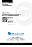
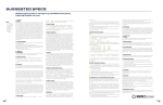
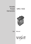
TOTALIFT T-Series Portable MVC 110/120 ® Constant Current Multivoltage User Manual INDEX 1. SAFETY INSTRUCTIONS AND WARNINGS ................................................ 3 GENERAL ..................................................................................................................... 3 SHOCK PREVENTION ................................................................................................. 3 BURN AND BODILY INJURY PREVENTION .............................................................. 4 FIRE AND EXPLOSION PREVENTION ....................................................................... 4 ARCING AND BURNING OF CONNECTOR ............................................................... 4 MEDICAL AND FIRST AID TREATMENT .................................................................... 4 2. DESCRIPTION OF THE CHARGER .............................................................. 5 3. INSTALLATION OF THE CHARGER............................................................. 5 AC INPUT CONNECTION ............................................................................................ 5 AC INPUT VOLTAGE SETTINGS ................................................................................ 6 4. HOW TO USE THE CHARGER ...................................................................... 8 PROGRAMMING SEQUENCE..................................................................................... 8 CHARGE PROCESS .................................................................................................. 10 END OF CHARGE ...................................................................................................... 11 MANUAL STOP .......................................................................................................... 12 OVERCURRENT PROTECTION ............................................................................... 12 SHUTDOWN ON BATTERY DISCONNECTION ....................................................... 13 PROGRAMMING MEMORY ....................................................................................... 13 __________________________________________________________________________________________________________________________________________________ Page 2/13 1. SAFETY INSTRUCTIONS AND WARNINGS Before using your TOTALIFT TsMVC battery charger, please take the time to read these instructions carefully. The owner’s manual is an important part of the charger. It’s recommended to keep it in good condition for the lifetime of the charger. It should be kept in a dry and clean place, always available to the users. To indicate important instructions, the following blocks are used throughout this manual. CAUTION! This operation can be dangerous for the user. ATTENTION! This operation is important for the functionality and reliability of the charger. GENERAL Battery charging products can cause serious injury or death, or damage to other equipment or property, if the operator does not strictly observe all safety rules and take precautionary actions. Safe practices must be learned through study and training before using this equipment. Only qualified personnel should install, use, or service this equipment. SHOCK PREVENTION Bare conductors or terminals in the output circuit, or ungrounded, electrically-live equipment can fatally shock a person. To protect against shock, have competent electrician verify that the equipment is adequately grounded and identify what terminals and parts are electrically HOT. The body’s electrical resistance is decreased when wet, permitting dangerous current to flow through the body. Do not work in a damp area without being extremely careful. Stand on dry rubber mat or dry wood and use insulating gloves when dampness or sweat cannot be avoided. Keep clothing dry. INSTALLATION AND GROUNDING - A power disconnect switch must be located at the equipment. Check the data label for voltage and phase requirements. If only 3-phase power is available, connect single-phase equipment to ONLY TWO WIRES of the 3-phase line. DO NOT CONNECT the equipment grounding conductor to the third live wire of the 3-phase line as this makes the equipment frame electrically HOT, which can cause a fatal shock. If a grounding conductor is part of the power supply cable, be sure to connect it to a properly grounded switch box or building ground. If not part of the supply cable, use a separate grounding conductor. Don’t remove a ground prong from any plug. Use correct mating receptacles. Check ground for electrical continuity before using equipment. The grounding conductor must be of a size equal to or larger than the size of the line conductors. CHARGING LEADS – Inspect leads often for damage to the insulation. Replace or repair cracked or worn leads immediately. Use leads having sufficient capacity to carry the operating current without overheating. BATTERY TERMINALS – Do not touch battery terminals while equipment is operating. __________________________________________________________________________________________________________________________________________________ Page 3/13 SERVICE AND MAINTENANCE – Shut OFF all power at the disconnect switch or line breaker BEFORE inspecting, adjusting, or servicing the equipment. Lock switch OPEN (or remove line fuses) so that the power cannot be turned ON accidentally. Disconnect power to equipment if it is to be left unattended or out of service. Disconnect battery from charger. Keep inside parts clean and dry. Dirt and/or moisture can cause insulation failure. This failure can result in high voltage at the charger output. BURN AND BODILY INJURY PREVENTION The battery produces very high currents when short circuited, and will burn the skin severely if in contact with any metal conductor that is carrying this current. Do not permit rings on fingers to come in contact with battery terminals or the cell connectors on top of the battery. Battery acid is very corrosive. Always wear correct eye and body protection when near batteries. FIRE AND EXPLOSION PREVENTION When batteries are being recharged, they generate hydrogen gas that is explosive in certain concentrations in air (the flammability or explosive limits are 4.1% to 72% hydrogen in air). The spark-retarding vents help slow the rate of release of hydrogen, but the escaping hydrogen may form an explosive atmosphere around the battery if ventilation is poor. The ventilation system should be designed to provide an adequate amount of fresh air for the number of batteries being charged. This is essential to prevent an explosion. Always keep sparks, flames, burning cigarettes, and other sources of ignition away from the battery recharging area. Do not break "live" circuits at the terminals of batteries. Do not lay tools or anything that is metallic on top of any battery. ARCING AND BURNING OF CONNECTOR To prevent arcing and burning of the connector contacts, be sure the charger is OFF before connecting or disconnecting the battery. The ammeter should NOT indicate current flow. MEDICAL AND FIRST AID TREATMENT First aid facilities and a qualified first aid person should be available for each shift for immediate treatment of electrical shock victims. EMERGENCY FIRST AID: Call physician and ambulance immediately and use First Aid techniques recommended by the American Red Cross. DANGER: ELECTRICAL SHOCK CAN BE FATAL. If person is unconscious and electric shock is suspected, do not touch person if he or she is in contact with charging equipment, battery, charging leads, or other live electrical parts. Disconnect power at wall switch and then use First Aid. Dry wood, wooden broom, and other insulating material can be used to move cables, if necessary, away from person. IF BREATHING IS DIFFICULT, give oxygen. IF NOT BREATHING, BEGIN ARTIFICIAL BREATHING, such as mouth-to-mouth. IF PULSE IS ABSENT, BEGIN ARTIFICIAL CIRCULATION, such as external heart massage. In case of acid in the eyes, flush very well with clean water and obtain professional medical attention immediately. __________________________________________________________________________________________________________________________________________________ Page 4/13 2. DESCRIPTION OF THE CHARGER TOTALIFT TsMVC battery chargers have been designed to charge Lead-Acid batteries. These units are based on a ferroresonant power transformer, with constant current output. Two models are available: TOTALIFT TsMVC 25: TOTALIFT TsMVC 50: Output current 25 A AC input 105/120 Vac – 15 A Output current 50 A AC input 230/250 Vac – 15 A The operation of the TOTALIFT TsMVC chargers is managed by a digital, programmable control board of the latest generation, which includes flat membrane keyboard and LCD display. 3. INSTALLATION OF THE CHARGER Conditions of use: Operating temperature: Storage temperature: Relative humidity: 5°C to 45°C -20°C to 60°C less than 75% CAUTION! Risk of electrical shock! The charger can be installed by qualified personnel only. To prevent fire or shock hazard, do not expose the unit to rain or moisture. Don't use the unit in presence of flammable gas, because it can generate sparks. ATTENTION! Make sure that the unit's maximum input power (reported on the data label) is available from your power supply, and verify that the unit's operating voltage is correct. Allow adequate air circulation to prevent internal heat buildup. Don't place the unit near heat sources such as radiators or air ducts, or in a place subject to direct sunlight, excessive dust, mechanical vibration or shock. __________________________________________________________________________________________________________________________________________________ Page 5/13 The model TOTALIFT TsMVC25 is already equipped with the adequate cable and plug AC INPUT CONNECTION The charger must be connected to the AC input using an adequate cable and plug, with disconnect switch and fuses. The AC input wires have to be connected to the TERMINAL BLOCKS FOR AC INPUT CABLE, that are located over the main transformer (see picture on the next page). Make sure to tighten the terminal block screws with the right torque, and pull each wire separately in order to verify that they are mounted properly. AC INPUT VOLTAGE SETTINGS ATTENTION! The proper setting of the power transformer taps is fundamental for the correct operation of the Totalift TsMVC chargers. If the real AC input voltage is different than the AC nominal voltage to which the charger is set, the charging current of the charger may be significantly different than the nominal. With reference to the following pictures, find the POWER TRANSFORMER TAPS and the label with the list of the NOMINAL voltages available that are located on the left side of the internal panel. TsMVC 25 TsMVC 50 1 1x 120 VAC 1x 250 VAC 2 1x 115 VAC 1x 240 VAC 3 1x 110 VAC 1x 230 VAC 4 1x 10⁵ VAC // Using an adequate AC-voltmeter, measure the value of the REAL AC input voltage available at the mounting location of the charger. Identify which of the NOMINAL voltage values is closest to the REAL measured value. Example : for a charger TsMVC 25 if the measured voltage is 117 VAC, the transformer should be connected to the tap number 2, that corresponds to 115 VAC. TsMVC 25 TsMVC 50 __________________________________________________________________________________________________________________________________________________ Page 7/13 4. HOW TO USE THE CHARGER PROGRAMMING SEQUENCE 1) Connect the Charger to AC input. The display shows the message: Charger Ready No Battery 2) Connect a battery. The display shows alternatively these messages for 10 seconds: ANALYZING THE BATTERY PRESS ENTER TO CHANGE PROGRAM If the user does not press the ENTER button within this 10 second period, the charge begins automatically, and the charge parameters are set automatically, following these rules: The Ah limit will be the same that was programmed in the previous charge cycle. The factory setting for this parameter is 2000 Ah. The Maximum time limit will be the same that was programmed in the previous charge cycle. The factory setting for this parameter is 12 h. The Maximum voltage limit is calculated as the 140% of the measured battery voltage. If the ENTER button is pressed during the 10 seconds, the display will show the measured battery voltage: Vbatt = xx.x V Press any key Where “xx.x” is the measured battery voltage. __________________________________________________________________________________________________________________________________________________ Page 8/13 3) Press any key. The display shows the message: Set Charge Time > 12 Hours < By pushing the buttons + and -, set the desired charge time. Min programmable time: Maximum programmable time: 1 h. 96 h. By pushing the ENTER button, the value is saved. 4) The display shows the message: Set Ah Limit > 2000 Ah < By pushing the buttons + and -, set the desired Ah limit. Min programmable capacity: Maximum programmable capacity: 10Ah. 2000Ah. By pushing the ENTER button, the value is saved. 5) The display shows the message: Set VOLT Limit > xx.x V < By pushing the buttons + and -, set the maximum Voltage limit, with steps of 0,1 V. Default value is 140% of the measured battery voltage. Min programmable Voltage: Maximum programmable Voltage: Measured value +1V. 70V. By pushing the ENTER button, the value is saved. 6) The board shows the message: > Start Charge Review Program __________________________________________________________________________________________________________________________________________________ Page 9/13 By pushing the buttons + and -, the “arrow” moves between the two lines, and the selection is made by pushing ENTER. If you select “REVIEW PROGRAM”, the board goes back to the beginning of the programming sequence. If you select “START CHARGE”, the charge process begins. CHARGE PROCESS The board shows the message: Starting ... Amps Time Volts Ah After 3 seconds, the charger begins, and the display shows: While the charge is in progress, the display continues to show the battery voltage (Volts), the charging current (Amps), the total capacity returned to the battery (Ah) and the charging time (hours and minutes). END OF CHARGE If the charge ends because the PROGRAMMED TIME is reached, the display shows the following messages (alternately): C HA R G E C OM P L E T E Max Time Reached ... Volts Ah Amps Time If the charge ends because the MAX PROGRAMMED CAPACITY is reached, the display shows the following messages (alternately): C HA R G E C OM P L E T E Max Ah Reached __________________________________________________________________________________________________________________________________________________ Page 10/13 ... Volts Ah Amps Time If the charge ends because the MAXIMUM PROGRAMMED VOLTAGE is reached, the display shows the following messages (alternately): C HA R G E C OM P L E T E Max Volt Reached ... Volts Ah Amps Time MANUAL STOP If, during the charge, any button is pressed, the display gives the message (for 5 seconds): > Sto p Charge Modify Program By pushing the buttons + and -, the “arrow” moves between the two lines, and the selection is made by pushing ENTER. If you select “STOP CHARGE”, the charge is stopped and the board gives the message: CHARGE STOPPED Press any key If one button is pressed, the board goes to the beginning of the programming sequence. If you select “MODIFY PROGRAM”, the board allows you to modifying the 3 programmed parameters, without stopping the charge. __________________________________________________________________________________________________________________________________________________ Page 11/13 If you don't make a selection within 5 seconds, the charge continues and the display goes back to the normal visualization: Volts Ah Amps Time OVERCURRENT PROTECTION If, during the charge, the current exceeds a max value (programmable with password, default value is 80A) for more than 5 seconds, the charge is stopped and the display shows these messages, alternately: OVERCURRENT SHUTDOWN !!! C H E C K V O L TA G E SETTINGS !!! __________________________________________________________________________________________________________________________________________________ Page 12/13 SHUTDOWN ON BATTERY DISCONNECTION CAUTION! NEVER disconnect the battery while it's being charged. Disconnecting the battery while it's being charged is hazardous for the user and voids the charger warranty. If the battery is disconnected while the charge is in progress, the TOTALIFT TsMVC charger will return automatically to stand-by mode. PROGRAMMING MEMORY The TOTALIFT TsMVC has a static memory that is used to save automatically the charge parameters programmed by the user. This exclusive feature allows the user to program the desired charging parameters only the first time when a battery is connected. The next time that the TOTALIFT TsMVC is powered and a battery is connected, all the parameters previously programmed by the user will be in memory, so the operation of the charger is always FULLY AUTOMATIC. End of Document - __________________________________________________________________________________________________________________________________________________ Page 13/13