1
Operating Instructions
VCE2500D«««
INDEX 001
TYROLIT No. 10992862 en / 19.04.2011
Congratulations!
You have decided to purchase a tried and tested TYROLIT-Hydrostress unit and have thus
acquired a highly sophisticated and reliable state-of-the-art unit. The exclusive use of only
TYROLIT Hydrostress spare parts ensures quality and interchangeability. If maintenance work is
neglected or carried out inexpertly we will be unable to honour our warranty obligations. Any
repair work must be carried out by trained personnel only.
Should you need more details concerning your TYROLIT Hydrostress unit in order to keep it in
perfect condition, please contact our after-sales service for further information.
We hope that you enjoy untroubled and fault-free working with your TYROLIT unit.
TYROLIT Hydrostress
Copyright © TYROLIT Hydrostress
TYROLIT Hydrostress AG
Witzbergstrasse 18
CH-8330 Pfäffikon
Switzerland
Telefon 0041 (0) 44 952 18 18
Telefax 0041 (0) 44 952 18 00
Konformitätserklärung
Declaration of conformity
Dust separator VCE2500D
We declare under our sole responsibility that this product complies with the following directives and standards:
Directive applied
Machinery Directives 2006/42/EC
EMV 2004/108/EG
Typenschild hier aufkleben
Applied standards
EN 60335-1: 2002 + A14 / EN 60335-2-69: 2009
EN 61000-6-3: 2007 / EN 61000-6-2: 2005
Déclaration de conformité
Staubabscheider VCE2500D
Séparateur de poussière VCE2500D
Wir erklären in alleiniger Verantwortung, dass dieses Produkt mit den folgenden Richtlinien und Normen übereinstimmt:
Nous déclarons, sous notre seule responsabilité, que ce produit répond aux directives et normes suivantes:
Angewandte Richtilinie
Directive appliquée
Maschinen-Richtlinien 2006/42/EG
EMV 2004/108/EG
Directive relative aux machines 2006/42/CE
EMV 2004/108/EG
Angewandte Normen
Normes appliquées
EN 60335-1: 2002 + A14 / EN 60335-2-69: 2009
EN 60335-1: 2002 + A14 / EN 60335-2-69: 2009
EN 61000-6-3: 2007 / EN 61000-6-2: 2005
EN 61000-6-3: 2007 / EN 61000-6-2: 2005
TYROLIT 10991213
Dichiarazione di conformità CE
Abbattitore delle polveri VCE2500D
Dichiariamo sotto la nostra completa responsabilità che il presente prodotto è conforme alle seguenti direttive e norme:
Direttiva applicata
Direttiva Macchine 2006/42/CE
EMV 2004/108/EG
Norme applicate
EN 60335-1: 2002 + A14 / EN 60335-2-69: 2009
EN 61000-6-3: 2007 / EN 61000-6-2: 2005
Declaración de conformidad CE
Separador de polvo VCE2500D
Declaramos bajo propia responsabilidad que este producto cumple con las siguientes directivas y normas:
Directiva aplicada
Directiva de Máquinas 2006/42/CE
EMV 2004/108/EG
Normas aplicadas
TYROLIT Hydrostress AG
Witzbergstrasse 18
CH-8330 Pfäffikon
Switzerland
EN 60335-1: 2002 + A14 / EN 60335-2-69: 2009
EN 61000-6-3: 2007 / EN 61000-6-2: 2005
Pfäffikon, 19.07.2012
Pascal Schmid
Leiter Entwicklung
7\UROLW9&('
1
2
3
Table of contents
Introduction
1
1.1 General Information .........................................................
1.2 Responsibility ..................................................................
1.3 Manual .............................................................................
1.3.1 Safety instructions – Explanation of symbols .....
1.4 Transportation .................................................................
1.5 On delivery ......................................................................
1.6 Unpacking .......................................................................
1.7 Machine name plate ........................................................
1.8 Handling and storage ......................................................
1.9 Noise ...............................................................................
1
1
1
1
2
2
3
3
4
4
Safety
5
2.1 General Information .........................................................
2.2 Warnings .........................................................................
2.3 Notes ...............................................................................
5
5
6
Machine description
8
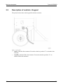
3.1 General machine description ........................................... 8
3.2 Description of controls - Keypad ..................................... 10
4
Usage
11
4.1 General Information .........................................................
4.2 The positions for the dust extractor .................................
4.2.1 The dust extractor's operating position ...............
4.2.2 Lowering the dust extractor to the transport
position ...............................................................
4.3 Lifting the machine ..........................................................
4.4 Handling Longopac .........................................................
4.4.1 Removing the full waste bag ..............................
4.4.2 Fitting Longopac .................................................
4.5 Installing extra ventilation hose .......................................
4.6 Operation .........................................................................
4.6.1 Starting and stopping the dust extractor .............
4.6.2 Filter cleaning .....................................................
11
11
11
13
15
15
16
17
21
22
22
23
i
Table of contents
5
Maintenance and repairs
7\UROLW9&('
26
5.1 General Information ......................................................... 26
5.2 Cleaning .......................................................................... 26
5.3 Daily ................................................................................ 26
5.3.1 Check the HEPA filter ......................................... 26
5.3.2 Check the main filter ........................................... 29
5.4 Every week ...................................................................... 30
5.4.1 General inspection ............................................. 30
5.5 Every month .................................................................... 31
5.5.1 Check the condition of the hoses. ...................... 31
5.6 Every six months (or 600 hours) ..................................... 31
5.6.1 Check the fastening of the bolts ......................... 31
5.7 Every year ....................................................................... 31
5.7.1 Replace the HEPA filter ...................................... 31
5.7.2 Replace main filter .............................................. 31
5.8 Repairs ............................................................................ 32
5.9 Spare parts ...................................................................... 32
6
Faultfinding
33
6.1 General Information ......................................................... 33
6.1.1 The dust extractor will not start .......................... 33
6.1.2 The dust extractor stops after starting ................ 33
7
Technical data
34
8
Environment
37
9
Warranty and CE marking
38
9.1 Warranty .......................................................................... 38
9.2 CE marking ...................................................................... 38
ii
7\UROLW9&('
Introduction
1
Introduction
1.1
General Information
7<52/,79&('3LVDGXVWH[WUDFWRUZKLFKLVEHVWXVHGWRJHWKHUZLWK+7&
V
JULQGLQJPDFKLQHVLQFRQQHFWLRQZLWKGU\JULQGLQJRIVWRQHDQGFRQFUHWHIORRUV
DQGLQDFFRUGDQFHZLWK+7&
VUHFRPPHQGDWLRQV9&('3LVHTXLSSHGZLWKDPDLQ
ILOWHUDVZHOODVD+(3$ILOWHUThe dust sucked up is collected in a bag under the
dust extractor.
Read the manual carefully so that you know how to use and maintain the dust extractor
before using it. Contact your local retailer for further information. For contact
information, see Contact Information at the start of the manual.
1.2
Responsibility
Even though every effort has been made to make this manual as complete and accurate
as possible, we bear no responsibility for incorrect or missing information. Tyrolit
Hydrostress® reserves the right to change descriptions in this manual without giving prior notice.
This manual is protected by the Copyright Act and no part of it may be copied or used
in any other way without the written approval of Tyrolit Hydrostress®.
1.3
Manual
In addition to general functions, this manual contains information on areas of use and
care of the dust extractor.
1.3.1
Safety instructions – Explanation of symbols
A number of symbols are used in the manual to highlight the most important sections,
see below. It is important that you carefully read through the descriptions of the symbols
in order to avoid the risk of both material damage and personal injury. There are other
symbols indicating practical tips. These are to help you use the dust extractor in the
easiest and most effective way.
The following symbols are used in the document to indicate where special attention is
needed.
Warning!
This symbol means Warning! and indicates a risk of personal injury or material
damage in the event of incorrect use of the dust extractor. When you see this
symbol, read the accompanying text extra carefully, and do nothing you are not
sure about. This is for your own and other users’ safety and to avoid damage to
the dust extractor.
2.0
1
7\UROLW9&('
Introduction
Note!
This symbol means Note! and indicates a potential risk of material damage in
the event of incorrect use of the dust extractor. When you see this symbol, read
the accompanying text extra carefully, and do nothing you are not sure about.
This is to avoid damage to the dust extractor.
Tip!
This symbol means Tip! and implies the inclusion of tips and advice on
effective use of the machine or ways of reducing wear and tear to the dust
extractor. When you see this symbol you should read the accompanying text to
facilitate your work and prolong the service life of the dust extractor.
1.4
Transportation
Always ensure that the dust extractor is emptied of dust and other particles before it is
transported, lifted or hoisted.
Always make sure that the dust extractor is securely anchored to its surroundings during
transport to prevent it from moving. Make sure that the securing straps or other
equipment used for anchoring during transport are tightened over non-moving parts, e.g.
the dust extractor's chassis.
When lifting the machine, do so according to chapter Lifting the machine, page 15.
Do not transport the dust extractor on sloping surfaces, e.g. loading ramps, without
securing it properly, for example with a winch. This is a safety measure in case the dust
extractor starts to roll out of control. Also make sure that people (including the operator)
in the vicinity are at a safe distance in order to prevent personal injury, in the event that
the dust extractor starts to roll out of control.
When the dust extractor is to be hoisted, it must be securely anchored in the notches for
secure lifting (position 4 Figure 3-2, page 9), which are found on both of the chassis'
long sides. To prevent the dust extractor from tipping, make sure to pull with equal
force so the dust extractor doesn't twist and end up on its side.
The swivelling wheel must be pointing forwards in the direction of travel.
1.5
On delivery
The following items are included in the delivery. Contact your retailer if anything is
missing.
2
•
Dust extractor
•
Manual disc
2.0
7\UROLW9&('
•
1.6
Introduction
Suction hose with couplings
Unpacking
Warning!
Read carefully through the safety instructions and user manual before using the
equipment.
•
•
1.7
Check carefully to see if the packaging or the dust extractor has been damaged
during delivery. If there is any sign of damage, contact your retailer and report it.
Check that the delivery matches the order. If there are any discrepancies, contact
your retailer.
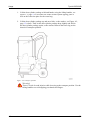
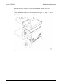
Machine name plate
The machine name plate provides the following information. The model and serial
number must be specified when ordering spare parts for the machine.
Figure 1-1. Machine name plate
2.0
1.
Model
2.
Model number
3.
Serial number
4.
Year of manufacture
5.
Power (kW)
6.
Voltage (V)
7.
Current (A)
8.
Frequency (Hz)
9.
Weight (kg)
10.
Address field
3
7\UROLW9&('
Introduction
1.8
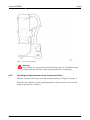
Handling and storage
The dust extractor should be stored in a heated, dry area when not in use. Otherwise it
may be damaged by condensation and cold.
The dust extractor can be lowered to the transport position, which facilitates transport
and maintenance work. Always ensure that the dust extractor is securely fastened to the
handle (Figure 3-2, page 9, pos 3), e.g. with lifting straps, during high lifts. Make
sure that all the constituent parts of the machine are properly assembled before lifting.
Warning!
If handled carelessly, the dust extractor can overturn and cause both personal
injury and damage to the equipment.
1.9
Noise
Warning!
Always use hearing protection when using the dust extractor
This dust extractor is tested for noise in accordance with ISO 11202 and ISO 3741. For
information on the sound pressure level and sound power level for each model, see the
table in Chapter Technical data, page 34.
4
2.0
7\UROLW9&('
Safety
2
Safety
2.1
General Information
This chapter contains all the warnings and notes that have to be considered for the dust
extractor.
2.2
Warnings
Warning!
Read carefully through the safety instructions and user manual before using the
equipment.
Warning!
Always use hearing protection when using the dust extractor.
Warning!
The dust extractor may only be used or repaired by personnel who have
received the requisite theoretical and practical training and who have read the
user manual.
Warning!
Always use the dust extractor in an environment where there is no risk of
explosion and fire. Familiarise yourself with and follow the relevant fire safety
regulations when using the dust extractor.
Warning!
Use protective equipment such as safety shoes, safety goggles, protective
gloves, breathing mask and hearing protection.
Warning!
During use, some surfaces on the dust extractor become very hot. Use
protective gloves and let the dust extractor cool a little before you touch it.
Warning!
The dust that is sucked up is harmful if inhaled. Follow local regulations and
use breathing protection.
Warning!
During maintenance and repairs, the power to the dust extractor must be
disconnected.
2.0
5
Safety
HTC GL 25/35 D
Warning!
Do not rinse off the dust extractor, as moisture can penetrate to the electrical
parts and damage the motors as well as causing an electrical shock.
Warning!
Do not rinse off the dust extractor, as moisture can penetrate into the HEPA
filter and main filter.
Warning!
The dust extractor must always be placed on a horizontal service during
operation. There is a risk for crush injuries, if it should start to roll.
Warning!
Connect the dust extractor to an earth fault breaker.
Warning!
In the case of careless handling, the dust extractor can overturn and can cause
both personal injury and damage to the equipment.
Warning!
There is a risk of crush injuries while lowering to the transport position. Use the
lifting handles to avoid trapping your hands and fingers.
2.3
Notes
Note!
The dust extractor is best used together with7\UROLW+<'52675(66
grinding machines inconnection with dry grinding of stone and concrete floors,
and in accordancewith7\UROLW+<'52675(66 recommendations.
Note!
Never use the dust extractor in connection with wet grinding or to suck up
moisture and water, since this can cause blockages in the dust extractor's
suction hose as well as damage to the main filter, HEPA filter and motors.
Note!
Only use original spare parts from7\UROLW+<'52675(66 for the dust extractor.
Otherwise,neither the CE marking nor the warranty will be valid.
Note!
For the CE marking to be valid, the instructions in this manual must be
followed.
6
2.0
7\UROLW9&('
Safety
Note!
The dust extractor should be stored in a dry, warm (above zero) location when
not in use.
Note!
If the dust extractor is stored in a cold location (below zero), it must be placed
in a warm location (above zero) for at least two hours before use.
Note!
Discolouration on the top of the HEPA filter indicates that the main filter is not
functioning as it should. If the HEPA filter is dirty on the underside, the filter is
defective.
Note!
When checking the HEPA filter, the dust extractor must be placed in the
operating position.
2.0
7
Machine description
3
Machine description
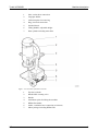
3.1
General machine description
7\UROLW9&('
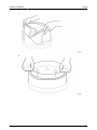
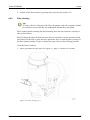
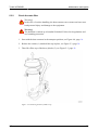
The VCE2500DP is constructed from a number of main components,
such as chassis, electrical cabinet, etc, see Figure 3-1, page 8 and Figure 3-2, page 9. Several different designs are available, adapted for different markets. For
model variants, see the table in Technical data, page 34. The dust that is vacuumed up
is captured in a Longopac bag, which can be sealed when the desired quantity of dust
has been reached.
Figure 3-1. The front of the dust extractor
8
2.0
7\UROLW9&('
Machine description
1.
Inlet, suction hose connection
2.
Longopac holder
3.
Collection plate for waste bag
4.
Plug, electrical connection
5.
Guides/Chassis
6.
Lifting handles, adjustable height
7.
Dust cylinder including main filter
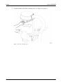
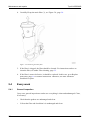
Figure 3-2. The back of the dust extractor
2.0
1.
Top dust cylinder
2.
Handle filter cleaning valve
3.
Handle
4.
Attachment point for lifting the machine
5.
HEPA filter holder
6.
Outlet, ventilation hose connection (ø 160 mm)
7.
Motor package including HEPA filter
9
Machine description
3.2
7\UROLW9&('
Description of controls - Keypad
The picture below shows the keypad for the dust extractor.
Figure 3-3. Keypad
•
•
10
I (ON)- Start the dust extractor: Press the switch to position "I" to start the dust
extractor.
O (OFF)- Switch off the dust extractor: Press the switch to position "O" to
switch off the dust extractor.
2.0
7\UROLW9&('
Usage
4
Usage
4.1
General Information
The following section describes the different positions for the dust extractor and how to
change the waste bag (Longopac). The section also deals with the operation of the dust
extractor.
Warning!
The dust extractor may only be used or repaired by personnel who have
received the requisite theoretical and practical training and who have read the
user manual.
Warning!
Use protective equipment such as safety shoes, safety goggles, protective
gloves, breathing mask and hearing protection.
Warning!
The dust extractor must always be placed on a horizontal service during
operation. There is a risk for crush injuries, if it should start to roll.
Tip!
Check the minimum recommended cable area before using an extension cord.
You will find the recommended cable area under Technical data, page 34.
4.2
The positions for the dust extractor
The dust extractor can be placed in two positions; operating position and transport
position, see Figure 4-3, page 13 and Figure 4-4, page 14.
Warning!
If handled carelessly, the dust extractor can overturn and cause both personal
injury and damage to the equipment.
4.2.1
The dust extractor's operating position
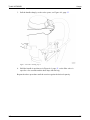
When the dust extractor is in use, it must be in the operating position, see Figure 4-3,
page 13.
2.0
11
7\UROLW9&('
Usage
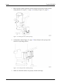
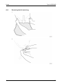
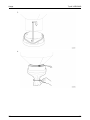
1. Raise the dust cylinder package from the transport position by lifting with the
lifting handles, see Figure 3-1, page 8, according to Figure 4-1, page 12.
Figure 4-1. Raising the dust cylinder package
2. Lift until the catches Figure 4-2, page 12 fasten firmly in the top lug on the
chassis for operating position.
Figure 4-2. Locking the dust cylinder package
3. Make sure that both catches are properly located in the lugs.
12
2.0
7\UROLW9&('
Usage
Figure 4-3. Operating position
Warning!
If the catches are not properly located in the lugs, there is a risk that the dust
cylinder package can drop, with a consequential risk of crush injury.
4.2.2
Lowering the dust extractor to the transport position
The dust extractor can be lowered to the transport position, see Figure 4-4, page 14.
When the dust extractor is in the operating position, and you want to lower it to the
transport position, do as follows:
2.0
13
7\UROLW9&('
Usage
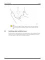
1. Lift the dust cylinder package with both hands, using the lifting handles, see
Figure 3-1, page 8. To avoid the risk of the suction system tipping, place a
foot on the collection plate for the waste bag.
2. Lift the dust cylinder package up and out a little, so the catches, see Figure 4-2,
page 12, release. Then let the dust cylinder package drop slightly and fold in
the dust cylinder package again, so the catches fasten in the lower lug on the
chassis for transport position.
Figure 4-4. Transport position
Warning!
There is a risk of crush injuries while lowering to the transport position. Use the
lifting handles to avoid trapping your hands and fingers.
14
2.0
7\UROLW9&('
4.3
Usage
Lifting the machine
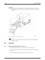
When lifting the dust extractor, lifting straps are used that are fastened in the notches on
the chassis, see Figure 4-5, page 15. Only use straps approved for lifting equipment.
Figure 4-5. Lifting eye
4.4
Handling Longopac
The dust extractor is equipped with a sack system that makes it possible to minimise
dust exposure when changing waste bags. This sack system can be ordered. Please
contact Tyrolit Hydrostress®.
2.0
15
7\UROLW9&('
Usage
4.4.1
Removing the full waste bag
1.
2.
16
2.0
7\UROLW9&('
Usage
3.
4.
Tip!
Pull out a new length of empty Longopac down to the waste bag plate. This is
to create the best conditions for the waste to fall into the waste bag.
4.4.2
Fitting Longopac
When fitting Longopac bags, it is recommended that the dust extractor be in the
operating position, see Figure 4-3, page 13. 2.0
17
7\UROLW9&('
Usage
1.
2.
Tip!
The Longopac holder is attached by a bayonet fitting to the dust
extractor.
18
2.0
7\UROLW9&('
Usage
3.
4.
2.0
19
7\UROLW9&('
Usage
5.
6.
20
2.0
7\UROLW9&('
Usage
7.
Tip!
Pull out a new length of empty Longopac down to the waste bag plate.
This is to create the best conditions for the waste to fall into the waste
bag.
4.5
Installing extra ventilation hose
To improve the air while grinding, an extra ventilation hose can be installed on the dust
extractor. This extra ventilation option should be used while grinding floors that give
rise to toxic gases or if the room is very poorly ventilated.
2.0
21
7\UROLW9&('
Usage
Tip!
Only use the extra ventilation hose, which at the least must have ø 160 mm,
when necessary, since the dust extractor's capacity is reduced when the hose is
installed.
Figure 4-6. Installation of extra ventilation hose
Note!
Place the free end of the ventilation hose outdoors by pulling it through a
window or a door.
4.6
Operation
4.6.1
Starting and stopping the dust extractor
1. Place the dust extractor where you want to start the vacuuming work.
2. Connect the dust extractor to the mains supply. Use suitable cables for the dust
extractor.
3. Start the dust extractor by putting the switch into the position "I".
22
2.0
7\UROLW9&('
Usage
4. Switch off the dust extractor by putting the switch into the position "O".
4.6.2
Filter cleaning
Tip!
To ensure effective cleaning of the filter, all gaskets on the dust extractor should
be checked to ensure that they are undamaged and that they seal tightly.
Filter cleaning means cleaning the filter manually when the dust extractor's capacity to
take up dust reduces.
When cleaning the filter, the dust extractor must be switched on and in operation. Hold
your hand over the inlet or place the hose against the floor to attain negative pressure in
the dust cylinder package in order to obtain the most effective filter cleaning possible.
Clean the filter as follows:
1. Place your hand over the inlet, see Figure 4-7, page 23. Wait a few seconds.
Figure 4-7. Filter cleaning step 1
2.0
23
7\UROLW9&('
Usage
2. Grip the handle on the filter cleaning valve, see Figure 4-8, page 24.
Figure 4-8. Filter cleaning step 2
24
2.0
7\UROLW9&('
Usage
3. Pull the handle sharply, so the valve opens, see Figure 4-9, page 25.
Figure 4-9. Filter cleaning step 3
4. Hold the handle in position as in Figure 4-9, page 25, so the filter valve is
open for a few seconds and the dust drops into the bag.
Repeat the above procedure until the suction regains the desired capacity.
2.0
25
Maintenance and repairs
5
Maintenance and repairs
5.1
General Information
7\UROLW9&('
We recommend regular inspection of the dust extractor.
Warning!
During maintenance and repairs, the power to the dust extractor must be
disconnected.
Warning!
Use protective equipment such as safety shoes, safety goggles, protective
gloves, breathing mask and hearing protection.
5.2
Cleaning
Warning!
Do not rinse off the dust extractor, as moisture can penetrate to the electrical
parts and damage the motors as well as causing an electrical shock.
•
Always clean the dust extractor after use by vacuum cleaning it or wiping it
down with a damp sponge or cloth.
5.3
Daily
5.3.1
Check the HEPA filter
Note!
When checking the HEPA filter, the dust extractor must be placed in the
operating position.
Warning!
The dust that is sucked up is harmful if inhaled. Follow local regulations and
use breathing protection.
26
2.0
7\UROLW9&('
Maintenance and repairs
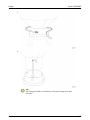
1. Undo the two quick fasteners (1) that hold the HEPA filter in place, see
Figure 5-1, page 27.
2. Lift the HEPA filter holder (2) out of the way, see Figure 5-1, page 27. Let the
HEPA filter holder and the hose hang freely.
Figure 5-1. Removing the HEPA filter holder
2.0
27
Maintenance and repairs
7\UROLW9&('
3. Lift out the HEPA filter (3), see Figure 5-2, page 28.
Figure 5-2. Removing the HEPA filter
4. Note how the HEPA filter is placed in the dust extractor.
Tip!
An arrow on the HEPA filter indicates the correct orientation for
installing the filter in the dust extractor so as to attain the flow in the
right direction through the filter. The arrow must point downwards, as
this is the direction of flow for the dust extractor.
5. Check whether the filter is dirty, discoloured or damaged.
6. If the filter is dirty, discoloured or damaged, it needs replacing. In this case, go to
Replace the HEPA filter, page 31 for further instructions. Otherwise, the filter
should be fitted back in place.
7. Check the gaskets on the HEPA filter. If the gaskets are damaged, the filter must
be changed.
28
2.0
7\UROLW9&('
5.3.2
Maintenance and repairs
Check the main filter
Warning!
In the case of careless handling, the dust extractor can overturn and can cause
both personal injury and damage to the equipment.
Warning!
The dust that is sucked up is harmful if inhaled. Follow local regulations and
use breathing protection.
1. Start with the dust extractor in the transport position, see Figure 4-4, page 14.
2. Release the catches (1) that hold the top in place, see Figure 5-3, page 29.
3. Then lift off the top of the dust cylinder (2), see Figure 5-3, page 29.
Figure 5-3. Removing the dust cylinder's top
2.0
29
Maintenance and repairs
7\UROLW9&('
4. Carefully lift up the main filter (3), see Figure 5-4, page 30.
Figure 5-4. Removing the main filter
5. If the filter is clogged, the filter should be cleaned. For instructions on how to
clean the filter, see under Filter cleaning, page 23.
6. If the filter is torn or defective, it should be replaced. In this case, go to Replace
main filter, page 31 for further instructions. Otherwise, the filter should be
fitted back in place.
5.4
Every week
5.4.1
General inspection
Carry out a general inspection to make sure everything is clean and undamaged. Clean,
if necessary.
30
•
Check that the gaskets are undamaged and clean.
•
Lift out the filter and check that it is undamaged and clean.
2.0
7\UROLW9&('
•
Maintenance and repairs
• Lift out the HEPA filter, to check the motor package, pos. 6 in Figure 3-2, page 9. Clean, if there is any dust.
5.5
Every month
5.5.1
Check the condition of the hoses.
•
Make sure that the hoses are undamaged and free from persistent dirt. Replace
the hoses, if necessary.
5.6
Every six months (or 600 hours)
5.6.1
Check the fastening of the bolts
•
Check the fastening of all bolts and screws. Tighten if required.
5.7
Every year
5.7.1
Replace the HEPA filter
Warning!
The dust that is sucked up is harmful if inhaled. Follow local regulations and
use breathing protection.
The HEPA filter must be replaced annually. However, if the daily inspection of the
HEPA filter shows that the filter should be replaced, follow the instructions in section
Check the HEPA filter, page 26.
1. Discard the defective filter.
2. Install the new HEPA filter. Take care to install it centrally in the HEPA filter
holder. An arrow on the HEPA filter indicates the correct orientation for
installing the filter in the dust extractor so as to attain the flow in the right
direction through the filter. The arrow must point downwards, as this is the
direction of flow for the dust extractor.
3. Secure the HEPA filter with the HEPA filter holder and both quick fasteners.
5.7.2
Replace main filter
Warning!
The dust that is sucked up is harmful if inhaled. Follow local regulations and
use breathing protection.
2.0
31
Maintenance and repairs
The main filter must be replaced annually. However, if the daily inspection of the main
filter shows that the filter should be replaced, follow the instructions in section Check
the main filter, page 29.
Check for damage to the HEPA filter, which may have occurred if dust has leaked out of
the main filter. For inspection of the HEPA filter, see section Check the HEPA filter,
page 26.
5.8
Repairs
Any repairs that may be required must be carried out by aTyrolit HYDROSTRESS®
Service Centre that has trained service personnel and usesTyrolit HYDROSTRESS®
original parts and accessories. Contact your retailer if your machine requires servicing.
For contact information, see Contact Information at the start of the manual.
5.9
Spare parts
To ensure rapid delivery of spare parts, always specify the model, the machine's serial
number and the spare part number when ordering. Information on the model and serial
number can be found on the machine's name plate.
Only original tools and original spare parts from Tyrolit HYDROSTRESS® may be used.
Otherwise neither the CE marking nor the warranty will be valid.
32
2.0
Safety
HTC GL 25/35 D
Warning!
Do not rinse off the dust extractor, as moisture can penetrate to the electrical
parts and damage the motors as well as causing an electrical shock.
Warning!
Do not rinse off the dust extractor, as moisture can penetrate into the HEPA
filter and main filter.
Warning!
The dust extractor must always be placed on a horizontal service during
operation. There is a risk for crush injuries, if it should start to roll.
Warning!
Connect the dust extractor to an earth fault breaker.
Warning!
In the case of careless handling, the dust extractor can overturn and can cause
both personal injury and damage to the equipment.
Warning!
There is a risk of crush injuries while lowering to the transport position. Use the
lifting handles to avoid trapping your hands and fingers.
2.3
Notes
Note!
The dust extractor is best used together with7\UROLW+<'52675(66
grinding machines inconnection with dry grinding of stone and concrete floors,
and in accordancewith7\UROLW+<'52675(66 recommendations.
Note!
Never use the dust extractor in connection with wet grinding or to suck up
moisture and water, since this can cause blockages in the dust extractor's
suction hose as well as damage to the main filter, HEPA filter and motors.
Note!
Only use original spare parts from7\UROLW+<'52675(66 for the dust extractor.
Otherwise,neither the CE marking nor the warranty will be valid.
Note!
For the CE marking to be valid, the instructions in this manual must be
followed.
6
2.0
Technical data
7
7\UROLW9&('
Technical data
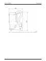
The tables and pictures below show the technical data and dimensions for the dust
extractor.
34
2.0
7\UROLW9&('
Technical data
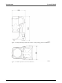
Figure 7-1. Height and length of the dust extractor, in the transport position, in millimetres
2.0
35
Technical data
7\UROLW9&('
Figure 7-2. Height and length of the dust extractor, in the operating position, in millimetres
Figure 7-3. Width of the dust extractor in millimetres
36
2.0
7\UROLW9&('
8
Environment
Environment
Tyrolit HYDROSTRESS® products are constructed mainly of recyclable metal and plastic.
The main materials used are listed below.
Machine part
Material
Waste management
Frame
Metal, powder-coated
Metal recycling
Front wheels
Metal, plastic and rubber
Metal recycling
Back wheels
Plastic
Plastic recycling/combustible
Cylinder
Metal, powder-coated
Metal recycling
Longopac holder
Plastic, ABS
Plastic recycling/combustible
Cover
Metal, powder-coated
Metal recycling
Camlock
Metal inc. aluminium
Metal recycling 1)
Hose
Plastic (PUR) and metal wire
Plastic recycling/combustible
HEPA filter Hepa 13
Metal, glass fibre reinforced paper
and hot-melt adhesive
Metal recycling 2)
Main filter
Metal, polyester and hot-melt
adhesive
Metal recycling 2)
Cables
Copper conductors with Neoprene
and PVC coating
Waste cable
Motor
Metal: Steel, aluminium and copper
Electronic waste
Chassis
Dust extractor
Electrical system
Electrical components Metal and plastic
Electronic waste
1)
If possible, different metals should be separated.
If the filter contains any hazardous substance from the grinding dust, it must be treated as
hazardous waste.
2)
For recycling and scrapping of components, see the applicable national regulations for
each country.
2.0
37
Warranty and CE marking
9
Warranty and CE marking
9.1
Warranty
7\UROLW9&('
This warranty only covers manufacturing defects.Tyrolit HYDROSTRESS® bears no
responsibility for damage that arises or occurs during transportation, unpacking or use.
In no instance andunder no circumstances shall the manufacturer be held responsible for
damage anddefects caused by incorrect use, corrosion or use outside the prescribed specifications.
The manufacturer is not responsible for indirect damage or costs under any
circumstances. For complete information on the manufacturer's warranty period, see
Tyrolit HYDROSTRESS® current warranty terms.
Local distributors may have special warranty terms specified in their terms of sale,
delivery and warranty. If there is any uncertainty regarding warranty terms, please
contact your retailer.
9.2
CE marking
CE marking of a product guarantees its free movement within the EU area in
accordance with EU regulations. CE marking also guarantees that the product fulfils
various directives (the EMC Directive and other possible requirements in so-called
directives for new procedures in accordance with these regulations). This machine
carries the CE mark in accordance with the Low Voltage Directive (LVD), the
Machinery Directive and the EMC Directive. The EMC Directive states that electronic
equipment must not disturb its surroundings with electromagnetic interference and also
that it must be immune to electromagnetic interference in its surroundings.
This machine is classified for use in environments such as heavy industry, light industry
and, for certain machine types, even in homes. See the Manufacturer’s Declaration of
Conformity, which shows that the machine is harmonised with the EMC Directive.
38
2.0