1
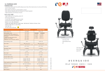
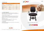
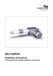
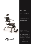
UK
user manual
VELA · Goeteborgvej 12 · DK-9200 Aalborg SV · Tel: +45 96 34 76 00 · [email protected] · www.vela.eu
www.vela.eu
Contents
7.0. Technical data
1.0. User manual . . . . . . . . . . . . . . . . . . . . . . . . . . . . . . . . . . . . . . . . . . . . . . . . . . . . . . . . 5
7.0.1. Chair identification number
The serial number is found on the chassis between the swivel wheels.
1.1. Before operation . . . . . . . . . . . . . . . . . . . . . . . . . . . . . . . . . . . . . . . . . . . . . . . . . . . 5
1.1.1. Entering and exiting. . . . . . . . . . . . . . . . . . . . . . . . . . . . . . . . . . . . . . . . . . . . . . . . . . . 5
1.1.2. Footplate. . . . . . . . . . . . . . . . . . . . . . . . . . . . . . . . . . . . . . . . . . . . . . . . . . . . . . . . . . . 5
1.1.3. Assistance exiting the chair . . . . . . . . . . . . . . . . . . . . . . . . . . . . . . . . . . . . . . . . . . . . . 6
7.0.2. Drive motors
Two HCM 560W worm-drive/gear motors.
Built-in electronic disc brakes.
1.2. Sitting position . . . . . . . . . . . . . . . . . . . . . . . . . . . . . . . . . . . . . . . . . . . . . . . . . . . . . 7
1.2.1. Armrest, fixed . . . . . . . . . . . . . . . . . . . . . . . . . . . . . . . . . . . . . . . . . . . . . . . . . . . . . . .
1.2.2. Armrest, folding. . . . . . . . . . . . . . . . . . . . . . . . . . . . . . . . . . . . . . . . . . . . . . . . . . . . . .
1.2.3. Seat height . . . . . . . . . . . . . . . . . . . . . . . . . . . . . . . . . . . . . . . . . . . . . . . . . . . . . . . . .
1.2.4. Chair back. . . . . . . . . . . . . . . . . . . . . . . . . . . . . . . . . . . . . . . . . . . . . . . . . . . . . . . . . .
1.2.5. Neck support . . . . . . . . . . . . . . . . . . . . . . . . . . . . . . . . . . . . . . . . . . . . . . . . . . . . . . .
1.2.6. Seat depth. . . . . . . . . . . . . . . . . . . . . . . . . . . . . . . . . . . . . . . . . . . . . . . . . . . . . . . . . .
1.2.7. Power tilt/seat tilt. . . . . . . . . . . . . . . . . . . . . . . . . . . . . . . . . . . . . . . . . . . . . . . . . . . . .
7
7
7
8
8
9
9
1.3. Operation
1.3.1. VR2 control box. . . . . . . . . . . . . . . . . . . . . . . . . . . . . . . . . . . . . . . . . . . . . . . . . . . . . . 10
1.3.2. Pilot+ control box (optional). . . . . . . . . . . . . . . . . . . . . . . . . . . . . . . . . . . . . . . . . . . . .10
1.3.3. Steering with joystick. . . . . . . . . . . . . . . . . . . . . . . . . . . . . . . . . . . . . . . . . . . . . . . . . . 11
1.3.4. Description of the powerchair’s controls . . . . . . . . . . . . . . . . . . . . . . . . . . . . . . . . . . . 11
1.3.5. Negotiating obstacles. . . . . . . . . . . . . . . . . . . . . . . . . . . . . . . . . . . . . . . . . . . . . . . . . . 12
1.3.6. Negotiating sloping surfaces . . . . . . . . . . . . . . . . . . . . . . . . . . . . . . . . . . . . . . . . . . . . 12
1.3.7. Braking . . . . . . . . . . . . . . . . . . . . . . . . . . . . . . . . . . . . . . . . . . . . . . . . . . . . . . . . . . . . .12
1.3.8. Electric brake. . . . . . . . . . . . . . . . . . . . . . . . . . . . . . . . . . . . . . . . . . . . . . . . . . . . . . . . 12
1.3.9. Standing still and parking. . . . . . . . . . . . . . . . . . . . . . . . . . . . . . . . . . . . . . . . . . . . . . . 13
1.4. Footrests
1.4.1. Folding footrests . . . . . . . . . . . . . . . . . . . . . . . . . . . . . . . . . . . . . . . . . . . . . . . . . . . . .
1.4.2. Electric swivel footrests (optional). . . . . . . . . . . . . . . . . . . . . . . . . . . . . . . . . . . . . . . . .
1.4.3. Electrically operated W-leg supports (optional). . . . . . . . . . . . . . . . . . . . . . . . . . . . . . .
1.4.4. Heel stops. . . . . . . . . . . . . . . . . . . . . . . . . . . . . . . . . . . . . . . . . . . . . . . . . . . . . . . . . .
14
14
14
14
7.0.3. Batteries
Two 12V 34Ah gel maintenance-free powerchair batteries.
Charging time approx. 8 timer with Universal 6a battery charging unit.
7.0.4. Electronics
Power network: 24 Volt DC Signal: analogue wiring PG drivers combined CR2 powerchair
electronics Electric lift: VELA Okin actuator BD 240/160 Tilt actuator: Linak RA60 24 VDC Electric back actuator:
Linak LA28 24 VDC Motorised control: VELA ET3.2 24VDC
7.0.5. Charger
Automatic Power Charger Classic 8A / 230 VAC
7.0.6. Dimensions
Seat height
Seat height front edge (no-load)
Height without seat
Vehicle width
Vehicle length with 1 footplate down
Clearance
Drive wheels
Swivel wheels, front
Swivel wheels, back
Seat tilt, electric
Back tilt, electric
48-68 cm
55 cm
44 cm
59 cm
92 cm
4 cm
10” (260x85 mm) flexell
6” (140 mm)
5” (120 mm)
13° back, 4° forward
27° (95° to 122°)
7.0.7. Driving properties
Max. speed
Range
Max. gradient
Obstacles, max.
Turning radius
Max. load
8 km/h, but supplied as standard
throttled down to 6.5 km/h
18 km/h
12°
4 cm
39 cm
125 kg
1.5. Position of control box
1.5.1. Fixed support. . . . . . . . . . . . . . . . . . . . . . . . . . . . . . . . . . . . . . . . . . . . . . . . . . . . . . . . 15
1.5.2. Catch bolt fitting (optional). . . . . . . . . . . . . . . . . . . . . . . . . . . . . . . . . . . . . . . . . . . . . 15
1.5.3. Parallel fitting tp IV (optional). . . . . . . . . . . . . . . . . . . . . . . . . . . . . . . . . . . . . . . . . . . . 15
1.6. Seat belt. . . . . . . . . . . . . . . . . . . . . . . . . . . . . . . . . . . . . . . . . . . . . . . . . . . . . . . . . . . . . 15
2
23
7.0. Transport
LASHING ring (OPTIONAL)
The chair can be fitted with a lashing ring which is used if the chair is to be transported by car, bus or
train. The lashing rings can only be mounted if the chair is configured with a C-profile seat frame.
(Contact VELA for further information)
2.0. Safety points. . . . . . . . . . . . . . . . . . . . . . . . . . . . . . . . . . . . . . . . . . . . . . . . . . . . . . . . 16
3.0. Maintenance
3.0.1. Batteries . . . . . . . . . . . . . . . . . . . . . . . . . . . . . . . . . . . . . . . . . . . . . . . . . . . . . . . . . . . 17
3.1. Charging
PASSENGER SEAT (OPTIONAL)
VELA Blues 100 can be configured for use as the passenger seat of a car. The chair must be
constructed as below, and the work must be carried out by a VELA technician or suitably trained
personnel.
3.1.1. Battery indicator . . . . . . . . . . . . . . . . . . . . . . . . . . . . . . . . . . . . . . . . . . . . . . . . . . . . . 17
3.1.2. Battery charging unit. . . . . . . . . . . . . . . . . . . . . . . . . . . . . . . . . . . . . . . . . . . . . . . . . . 18
3.1.3. What to do . . . . . . . . . . . . . . . . . . . . . . . . . . . . . . . . . . . . . . . . . . . . . . . . . . . . . . . . . 18
4.0. Maintenance and troubleshooting
ConfiguratAion for use as a passenger seat
For the VELA Blues 100 – 200 – 300 to be used as the passenger seat in a car, the chair must be
configured as shown below: (in case of doubt please contact VELA)
- SW seat and back system (width 40 – 45 – 50 cm)
- WB head restraint
- Folding or fixed armrest
4.0.1. Cleaning . . . . . . . . . . . . . . . . . . . . . . . . . . . . . . . . . . . . . . . . . . . . . . . . . . . . . . . . . . . 19
4.0.2. Maintenance. . . . . . . . . . . . . . . . . . . . . . . . . . . . . . . . . . . . . . . . . . . . . . . . . . . . . . . . 19
4.0.2. Troubleshooting. . . . . . . . . . . . . . . . . . . . . . . . . . . . . . . . . . . . . . . . . . . . . . . . . . . . . . 19
5.0. Guarantee and service. . . . . . . . . . . . . . . . . . . . . . . . . . . . . . . . . . . . . . . . . . . . . 21
6.0. Transport . . . . . . . . . . . . . . . . . . . . . . . . . . . . . . . . . . . . . . . . . . . . . . . . . . . . . . . . . . . 21
- Electric or manual chair back
- Electrically operated leg support or E-leg support + swivel footrest
Positioning the 3-point seat belt on the user
7.0. Technical data
IMPORTANT: The 3-point seat belt must not be tightened across
sharp edges.
The drawing illustrates the incorrect positioning of a 3-point
seat belt. The text in the figure states that seatbelts must not
be held away from the body by parts of the wheelchair, such
as armrests, wheels, etc.
6.0.1. Lashing rings . . . . . . . . . . . . . . . . . . . . . . . . . . . . . . . . . . . . . . . . . . . . . . . . . . . . . . . . 21
7.0.1. Chair identification number. . . . . . . . . . . . . . . . . . . . . . . . . . . . . . . . . . . . . . . . . . . . .
7.0.2. Drive motors . . . . . . . . . . . . . . . . . . . . . . . . . . . . . . . . . . . . . . . . . . . . . . . . . . . . . . . .
7.0.3. Batteries . . . . . . . . . . . . . . . . . . . . . . . . . . . . . . . . . . . . . . . . . . . . . . . . . . . . . . . . . . .
7.0.4. Electronics. . . . . . . . . . . . . . . . . . . . . . . . . . . . . . . . . . . . . . . . . . . . . . . . . . . . . . . . . .
7.0.5. Charger. . . . . . . . . . . . . . . . . . . . . . . . . . . . . . . . . . . . . . . . . . . . . . . . . . . . . . . . . . . .
7.0.6. Dimensions . . . . . . . . . . . . . . . . . . . . . . . . . . . . . . . . . . . . . . . . . . . . . . . . . . . . . . . . .
7.0.7. Driving properties . . . . . . . . . . . . . . . . . . . . . . . . . . . . . . . . . . . . . . . . . . . . . . . . . . . .
23
23
23
23
23
23
23
These two drawings illustrate the correct positioning of a 3-point seatbelt
The seatbelt must have full contact with the shoulder, chest and hips.
The lap belt must be positioned as close as possible to the hips.
22
3
Introduction
5.0. Warranty and service
Your new VELA Blues 200 powerchair is designed to make your life easier. We have devel-
Your VELA Blues 200 is covered by VELA’s 24-month factory warranty for any problems that can be attributed to defects in materials
oped an extremely compact powerchair for indoor use. With the drive wheels placed in the
middle, it requires very little space. VELA Blues 200 is designed for simple and logical
operation.
or manufacture. The warranty does not cover parts that suffer
wear, such as tyres, batteries, seat covers etc. VELA provides service
on weekdays.
When you move about indoors, you will appreciate being able to raise the seat to reach
across a table or take something down from a shelf. The seat lift is operated from the
powerchair’s control box or – depending on the individual construction of the chair – from
a separate tilt switch. The mid-wheel drive permits operation in very narrow spaces. After
some getting used to, it will quickly feel safe and natural. It can easily handle outdoor use,
as long as there is solid ground under the wheels.
6.0. Transport
We hope that your will be happy with your VELA Blues 200. By taking a few minutes to
read this manual, you will quickly gain an overview of the construction and possibilities
offered by the VELA Blues 200. Please keep this manual for future reference.
The height of the powerchair can be reduced to approx. 85 cm by
folding the chair back across the seat. Loosen the pin on the chair
back and remove it. Then fold the chair back across the seat.
Enjoy your VELA Blues 200.
6.0.1. Lashing rings
The powerchair is equipped with four lashing rings placed in the
corners of the chair.
Vermund Larsen A/S
VELA
Goeteborgvej 12
DK-9200 Aalborg
Denmark
www.vela.eu
Warning! The VELA Blues 200 is not approved as a passenger seat
for use in cars, buses or trains. Always make sure that the powerchair is secured using approved lashing equipment during transport
in cars, buses, trains etc.
The chair is not designed to be lifted during transport.
4
21
Part
Maintenance
Interval
Once a
month,
depending
on use
Wheels
User
Check that the tyres are not worn and that
stones or other objects are not sitting in
the tread.
If the wheels are pneumatic, check the air
pressure, which must be between 2.20-3.5
Kilo Pascal.
The wheel can be inflated with either a car
pump or at a service station.
Changing
wheels
VELA
Contact VELA
User
The control box and the rubber seal
around the joystick must always be kept
clean. Once a week, you should check that
the joystick returns to its original position
and that the rubber seal has not been
damaged. If this is not the case, contact
VELA.
Once a
week
1. Check the on-off switch.
2. Check the horn.
3. Check the speed – try accelerating and
decelerating.
4. Check the seat lift – raise and lower the
seat to its full extent.
5. Check the seat tilt – tilt the seat all the
way backwards and all the way forwards.
If any of the functions do not work or if
anything feels different to normal, contact
VELA.
Once a
month
Control box
Testing
control box
functions
20
Maintenance
carried out by
User
Batteries
VELA
Accessories
User
1.0. User manual
This powerchair is a class A (EN 12184) electric wheelchair. The first attempts to operate the chair
should be made in an area with plenty of floor space. Choose a low operating speed (press the
‘down button’ a few times) until you have become accustomed to the chair.
1.1. Before operation
Before starting the powerchair, you should check the following:
• The footrest is in place and both feet are placed properly on the footplate.
• The electric lift (seat lift) is in the lowest position.
• The electric tilt (seat tilt) is in neutral position.
• Both motors are connected (both disconnection arms are horizontal).
• The powerchair is turned on by pressing the I/O button.
1.1.1. Entering and exiting
Always turn off the power before entering or exiting the chair (the I/0 button).
1.1.2. Footplate
The footplate can be folded up to allow you to place your feet on the floor.
Warning! Do not stand on the footplate or footrests – the chair can tip and you may loose your
balance.
Batteries must be replaced by VELA.
If the batteries are leaking, avoid touching
them as the contents are corrosive.
In the event
of flat or
defective
batteries
All accessories such as footrests, armrests
and body supports must be adjusted using
the tools supplied.
Once a
month
5
4.0. Maintenance and troubleshooting
1.1.3. Assistance exiting the chair
The electric seat lift can help in connection with entering and exiting the chair. For instance, the electric seat lift can be placed in the
highest position before sliding out over the front edge of the seat
4.0.1. Cleaning
Wipe/wash the wheels as needed using mild soap and water. Wipe
the protective motor cover with a soft cloth. Do not use abrasive
sponges or brushes. Clean the seat and back with a vacuum
cleaner or a brush. The fabric is a standard wool type, which has
been chosen for optimum comfort. It is not recommended that the
seat cover be washed as it may shrink. Dry-clean only.
with legs as stretched out as possible. The reverse procedure can be
followed when entering the chair.
If the powerchair is equipped with a power tilt function, tilting the
seat can be very helpful when exiting the chair: With the seat tilted
forwards, not as much strength is needed to climb out of the chair.
Do the opposite when entering the chair: With the seat tilted
backwards it is easier to climb into the chair.
The control box can be cleaned with a damp cloth and a little
washing-up liquid if necessary. The armrests can be wiped off with
a damp cloth and warm soapy water if necessary. The armrest is
normally covered in leather, and organic solvents must therefore
never be used.
4.0.2. Maintenance
Daily maintenance can be carried out by the user. Repairs and
servicing must be carried out by trained service staff or by a VELA
service technician. It is recommended that the powerchair is
serviced once a year by a VELA service technician when all moving
parts will be lubricated and checked for wear.
4.0.3. Troubleshooting
If your VELA Blues 200 should stop working, check the following
first:
Chair does not start
• Check that the connection handles are in the Drive position.
• Check the battery to see whether it is charged.
• C
heck that the overload protection is disengaged: Press the
overload switch all the way in (when the overload protection is
disengaged, the battery indicator will flash brightly).
Connection handles
The powerchair runs slowly
• Check that the seat is in the lowest position.
• Check that the speed selector on the control box is on max.
Chair loses power
• Check that the charging unit is connected correctly.
• C
heck that the charging functions normally (read LED lights on
front panel of charger).
• Call a service technician to have the condition/age of batteries checked.
• Call a service technician to have the wiring to batteries checked.
6
Overload protection
19
3.1.2. Battery charging unit
Batteries are charged using the accompanying charging unit (e.g.
Classic 8A). The charging time is approx. 8 hours, depending on
battery status. It is recommended that the batteries be charged
every night. The Universal 6a charging unit is fully automatic and
controls power and voltage during charging. When the batteries
are fully charged, power consumption will be minimal, so you can
safely leave the charging unit connected until the next time you use
your VELA Blues 200.
3.1.3. What to do
1. Park the chair and turn off the power (press the I/0 button).
2. Plug the charging unit into the socket on the front of the underside of the control box. NOTE! The chair cannot be turned
on when the charging unit is connected.
3.Plug the charging unit to the mains power (230 V) and turn it
on. The yellow light on the front panel of the charger shows
that the batteries are being charged.
4.When the batteries are fully charged, the ‘completed’ light on
the front panel of the charger will be green.
NOTE! For extended periods of disuse (days/weeks/months), the
battery charger should be connected to ensure optimum power
when your VELA Blues 200 is used again.
NOTE! In some cases, batteries that have been run down too far
(flat) cannot be recharged by the Universal 6a charging unit. This is
for your own safety, because dangerous vapours can develop when
flat batteries are recharged.Call your VELA service technician.
1.2. Sitting position
A correct sitting position is achieved when the chair back is placed
with approx. three fingers of space between the front edge of the
seat and the hollows of the knees. The chair back can be moved
(using tools) forwards and backwards above the seat to adjust the
seat depth (see 1.2.6.). The armrests are in the correct position
when the user is sitting up straight with elbows in to the body and
arms resting comfortably without lifting the shoulder blades.
1.2.1. Armrests, fixed
The height of the armrests can be adjusted by loosening the bolt
(using tools) on the armrest bar. Tighten again at the desired
height. The depth of the armrests, i.e. position in relation to the
front edge of the seat, can be adjusted by loosening the two bolts
in the armrest support.
The armrests can then be pushed forward and backward on the
seat’s c-rail. Tighten again in the desired position.
1.2.2. Armrests, folding
As an optional feature, the VELA Blues 200 powerchair can be
equipped with folding armrests. The height of the armrests can
be adjusted by loosening the handle on the armrest bar. Tighten
again in the desired position. It is possible to adjust the angle of the
armrest pillow by adjusting the top screw on the armrest bar (visible
when folded up).
1.2.3. Seat height
The VELA Blues 200 has an electric seat lift as standard equipment.
The electric lift function is operated (standard) from the control box.
Choose the electric lift function by pressing the function button
and pushing the joystick forwards to move the seat up or backwards to move the seat down. Depending on how the powerchair
is equipped, the electric lift function may be located in a tilt switch
(optional).
NOTE! For safety reasons, the electric lift must be at the lowest
position before driving on uneven terrain or sloping surfaces, before
driving the chair long distances or before operation at the highest
speed.
NOTE! For your own safety, the powerchair is equipped with an
automatic safety circuit that reduces the speed by 50% when the
electric tilt is raised 7 cm or more above the lowest position.
18
7
1.2.4. Chair back
The chair back features an adjustable shoulder support. By loosening the two hand screws, it is possible to tilt the shoulder support
forwards or backwards. To raise the chair back, loosen the two
bolts on the telescopic tube which is visible when the shoulder
support is folded back. The height of the chair back can now be
adjusted and increased by up to 10 cm.
Depending on how the powerchair is equipped, it may have: fixed
back tilt, manual back tilt or electric back tilt.
The fixed back tilt can be regulated (using tools) by adjusting the
tilt pole behind the chair back. The pole can be released from the
ball shaft at one end and either extended or shortened by turning
the ends in the middle piece. The manual back tilt can be adjusted
using the gas spring handle (push down) while pushing the chair
back into the desired position. Release the handle to secure the
chair back again.
The electric chair tilt can be operated from the tilt switch (normally
located on the same side as the control box).
1.2.5. Neck support
The height and position of the neck support (optional) are adjustable. By loosening both hand screws, the neck support can be
positioned as desired.
NOTE! If you need to raise the neck support, it is possible to raise
the shoulder support, see above.
8
3.0. Maintenance
3.0.1. Batteries
The VELA Blues 200 is equipped with two 34 Ah maintenancefree and vapour-free batteries. Good-quality new batteries provide
the equivalent of an operating range of 18 km. Experience shows
that this covers the daily needs of most users. The batteries are
dimensioned to be fully run down 220 times. Their lifetime will be
extended significantly if they are only partially run down before
charging. Defective batteries must be replaced with batteries of the
same type. We recommend that batteries be replaced by a service
technician.
NOTE! When installing batteries, extreme care must be taken to
connect +/- correctly. Red wire to the + pole. Incorrect connection
can damage the powerchair’s electronics.
NOTE! Batteries must not be disposed of with ordinary household
rubbish. Used batteries and other electrical equipment must be
deposited at an approved recycling centre according to the marking
on the product.
3.1. Charging
3.1.1. Battery indicator
The control box has a built-in battery indicator. For fully charged
batteries, three groups of coloured LEDs light up. During use, the
voltage in the batteries falls, and the row of lights decreases: The
lights go off one at a time.
• Green signal = DRIVE
• Yellow signal = Recharging needed soon
• Red signal = Recharging needed immediately
The battery indicator will flash to call attention to low battery
power.
17
2.0. Safety points
For your safety, the following should always be observed:
•The VELA Blues 200 is designed for limited outdoor use. It should only be operated on even
1.2.6. Seat depth
The seat depth can be regulated by pushing the chair back forwards
or backwards on the two c-rails: Loosen the two screws on either
side from the back hinge and release the sliding bar for the back
tilt. The chair back can then be pushed forwards or backwards.
and firm surfaces in places where the user feels confident.
• It must not be used outdoors at dusk or in the dark.
NOTE! Make sure to carefully tighten all bolts after adjustment.
• The VELA Blues 200 is as standard not approved as a passenger seat for use in cars, buses
1.2.7. Power tilt/seat tilt
Depending on how the powerchair is equipped, it may have: fixed
seat tilt or electric seat tilt. The fixed seat tilt can be adjusted by
regulating the bar’s support plate. (Request technical assistance.)
or trains.
• The chair is not designed to be lifted during transport.
•Always make sure that the powerchair is secured using approved lashing equipment during
transport in cars, buses, trains etc.
•Never stand on the footplates when entering or exiting the chair as this can cause the chair
to tip over.
The electric seat tilt is operated (standard) from the control box.
Choose the electric lift function by pressing on the function button
and pushing the joystick forwards to move the seat forwards or
backwards to move the seat backwards.
Depending on how the powerchair is equipped, the electric lift
function may be located in a tilt switch (optional).
•Always lower the electric seat lift to the lowest position before negotiating obstacles and
before moving at high speeds.
• Always lower the electric seat lift to the lowest position before negotiating sloping sur
faces.
•Never drive sideways or diagonally on a sloping surface as this can cause the chair to tip
over.
•The chair must never be exposed to rain or extreme moisture as it can damage the electronics.
•Never cover the battery charging unit during recharging as it produces heat. The battery
charging unit must be placed on a firm, well-ventilated surface.
•When moving backwards and when operating the electric functions, make sure that other
people are well out of the way.
•The wheelchair can be configured for use as a passenger seat during transport, but only
as a specially configured version (see item 6 re. transport)
16
9
1.3. Operation
1.5. Position of control box
1.3.1. VR2 control box
The VELA Blues 200 will normally be equipped with a VR2 control
1.5.1. Fixed support
The control box is mounted on either the right or the left side
according to customer specifications. The joystick is mounted as
standard on a fixed support. Its position can be regulated forwards
or backwards in relation to the armrest: Loosen the bolt on the sliding bar and place the control box in the desired position.
box. The powerchair is turned on and off on the I/0 button.The
‘speed up’ button increases operating speed: Press the button
repeatedly and you will see the indicator light move up.
The ‘speed down’ button reduces operating speed: Press the button
repeatedly and you will see the indicator light move down.
Force to mange the joystick:
Forward/backward: 1.3Nm
Sideways: 1.0 Nm
Two of the powerchair’s functions are controlled from the control
box (normally lift and tilt). Choose one of the functions by pressing
the function button, pushing the joystick forwards to move
forwards or backwards to move backwards. (It is possible to change
between the two functions by moving the joystick to the side). The
control box has a signal horn.
It is not possible for the user to re-program the control box.
1.3.2. Pilot+ control box (optional)
As an optional feature, the powerchair can be equipped with a
Pilot+ control box. The powerchair is turned on and off on the I/0
button. The function button allows you to switch between the
various functions: Press the function button once and immediately
move the joystick to the side. You will note that various indicator
lights on the control box show which (of up to five possible)
functions are activated: electric lift, seat tilt, chair back tilt, footrest
right, footrest left. Every time the joystick is moved to the side, it
changes to a new function. To operate a function, push the joystick
forwards (UP) or backwards (DOWN).
1.5.2. Catch bolt fitting (optional)
The easily adjustable catch bolt fitting makes it possible to lower
the control box so that the chair can e.g. come all the way up to a
table. The catch bolt is released by lightly pressing the polished lock
handle forward. It can be operated either from the side or from the
front. When the control box is pulled up and back into the operating position, the catch bolt automatically locks into place.
The position of the control box can be regulated forwards or backwards in relation to the armrest: Loosen the bolt on the sliding bar
and place the control box in the desired position.
1.5.3. Parallel fitting (optional)
The powerchair can be equipped with a swivel parallel fitting that
makes it possible to move the control box back along the armrest
so that the chair can e.g. come all the way up to a table.
The position of the control box can be regulated forwards or backwards in relation to the armrest: Loosen the bolt on the sliding bar
and place the control box in the desired position.
1.6. HIP STRAP
It is possible to equip the chair with a hip strap. This can be fitted to
the chair as shown in the accompanying guide.
Speed: The first option is to adjust speed. When the number in the
display flashes, you can increase your speed by pushing the joystick
forwards or decrease it by pushing the joystick backwards. (The
speed will appear as a number from 1 to 5 on the display.)
When you want to move again, press the function button and the
10
powerchair will return to the Drive position where the joystick is
pushed forwards to move forwards.
Force to mange the joystick:
Forward/backward: 1.3Nm
Sideways: 1.0 Nm
15
1.4. Footrests
1.4.1. Folding footplates
The VELA Blues 200 is equipped with a solid footplate. The footplate is attached to the undercarriage and can be folded up when
not in use.
1.3.3. Steering with joystick
Move the joystick in the direction you want the chair to move. Acceleration and speed are controlled by moving the joystick: Large
movement = fast acceleration and high speed. Small movement =
slow acceleration and low speed.
It is not possible for the user to reprogram the control box.
1.4.2. Electric swivel footrests (optional)
The VELA Blues 200 can also be equipped with a set of adjustable
footrests. The footrest can be moved out of the way when entering
and exiting the chair by lifting the bar approx. 3 cm up and swinging the footrest around the side at the same time. The depth of the
footrest can be adjusted using the tool for adjusting the sliding bar
in the seat frame either forwards or backwards.
The footrest can be adjusted to suit leg length by regulating the
length bar in its hollow tube. Using tools, the foot angle can be
adjusted by adjusting the swivel part of the footplate.
1.4.3. Electrically operated W-leg supports (optional)
This type of leg support can be raised electrically to almost a horizontal position. They are operated from the tilt switch or from the
control box (if the chair is equipped with the Pilot+ option). The leg
supports are operated individually.
Each leg support can be moved out of the way when entering and
exiting the chair by pushing the lock latch in and simultaneously
opening the leg support by swinging it around to the side. Now the
leg support can be removed or it can remain in the open position
when entering or exiting the chair.
The depth of the footrest can be adjusted using the tool for adjusting the hinge forwards or backwards on the seat’s c-rail. Adjust the
length of the leg using tools by regulating the length bar which is
kept in place by a bolt. The foot angle can be adjusted using the
tool in the swivel part of the footplate.
Warning! Do not subject the joystick and control box to vertical
pressure and do not push hard on the joystick as this can damage
parts in the box!
1.3.4. Description of the powerchair controls
Pushing the joystick forwards activates both wheels synchronously,
and the chair moves forwards. Pushing the joystick backwards
activates both wheels synchronously, and the chair moves in the opposite direction. If the joystick is pushed diagonally in one direction,
the speed is distributed between the two wheels asynchronously
(and in some cases in opposite directions). This will cause the chair
to move on a path in the desired direction.
NOTE! When changing directions, the chair’s swivel wheels must
change position: They will swing on the axel of the front fork until
the wheels are pointing in the direction you wish to go. When the
powerchair is standing still before changing direction in this way, a
lot of motor power is needed to drive the wheels. This power can
cause a jolt to the front end (leg supports) or back end (if the chair
is front-wheel drive) of the chair. The effects of this jolt can be
minimised by increasing power gradually and moderately (small
movements of the joystick).
Warning!
Despite an approved EMC test, we make no guarantee that the
powerchair is not affected by electromagnetic fields from e.g.
mobile phones and radio transmitters, or that the powerchair does
not transmit electromagnetic fields that can affect its surroundings,
such as e.g. shop security systems.
1.4.4. Heel stops
It is possible to fit heel stops to the footrests.
14
11
1.3.5. Negotiating obstacles
The VELA Blues 200 can handle a difference in surface level of up
to 4 cm, which makes it possible to cross e.g. doorsteps and many
types of ramps. Always drive as straight as possible when negotiating such obstacles. For abrupt changes in level, it helps to increase
the length and speed of your approach.
Warning! The electric seat lift must be lowered to the lowest position before negotiating obstacles as a raised seat reduces stability
and can cause the chair to tip over!
1.3.6. Negotiating sloping surfaces
The powerchair has enough traction to negotiate standard household ramps.
(Max. gradient with load of 75 kg: 12°). When moving down
ramps, the chair must always move perpendicular to the sloping
surface and at a slow speed.
Warning! The electric seat lift must always be lowered to the
lowest position before negotiating sloping surfaces as a raised seat
reduces stability and can cause the chair to tip over!
12
1.3.8.1. Emergency brake
The powerchair can be stopped immediately by turning it off: Press
the I/0 button.
Warning! When the powerchair is turned off, the electric brake is
activated immediately. This will cause a very sudden stop. The chair
must therefore only in emergencies be turned off while it is still
moving. There is a risk of the user falling out of the chair! There is a
risk of the chair tipping over!
1.3.8.2. Disengagement
Should it be necessary to manoeuvre the chair manually, the electric
brake and motor can be disengaged using the two disconnection
arms under the protective motor cover.
Note! It is not possible to operate the Blues 200 powerchair
electrically when the disengagement function is in use. Push both
disconnection arms back into the horizontal position immediately
after manoeuvring the chair.
Warning! The chair must never be driven diagonally or sideways
across a sloping surface as this can cause the chair to tip over!
Warning! Do not attempt to manoeuvre the chair manually when
the motor is still in gear, when the chair is on a sloping surface, on
a landing or in a similar situation where the chair might start rolling
or run out of control.
1.3.7. Braking
To stop the powerchair, return the joystick to the central position or
let go of it.
1.3.9. Standing still and parking
Always use the I/0 button to turn the powerchair off as soon as you
no longer want to drive it.
1.3.8. Electric brake
The VELA Blues 200 is equipped with an electric brake that is
activated automatically moments after the drive motors stop. This
brake ensures that the chair is fully locked when entering and exiting, parking on ramps etc.
NOTE! When the chair is turned on, battery power is consumed. It
is therefore a good idea to turn off the chair when it is parked.
13
1.4. Footrests
1.4.1. Folding footplates
The VELA Blues 200 is equipped with a solid footplate. The footplate is attached to the undercarriage and can be folded up when
not in use.
1.3.3. Steering with joystick
Move the joystick in the direction you want the chair to move. Acceleration and speed are controlled by moving the joystick: Large
movement = fast acceleration and high speed. Small movement =
slow acceleration and low speed.
It is not possible for the user to reprogram the control box.
1.4.2. Electric swivel footrests (optional)
The VELA Blues 200 can also be equipped with a set of adjustable
footrests. The footrest can be moved out of the way when entering
and exiting the chair by lifting the bar approx. 3 cm up and swinging the footrest around the side at the same time. The depth of the
footrest can be adjusted using the tool for adjusting the sliding bar
in the seat frame either forwards or backwards.
The footrest can be adjusted to suit leg length by regulating the
length bar in its hollow tube. Using tools, the foot angle can be
adjusted by adjusting the swivel part of the footplate.
1.4.3. Electrically operated W-leg supports (optional)
This type of leg support can be raised electrically to almost a horizontal position. They are operated from the tilt switch or from the
control box (if the chair is equipped with the Pilot+ option). The leg
supports are operated individually.
Each leg support can be moved out of the way when entering and
exiting the chair by pushing the lock latch in and simultaneously
opening the leg support by swinging it around to the side. Now the
leg support can be removed or it can remain in the open position
when entering or exiting the chair.
The depth of the footrest can be adjusted using the tool for adjusting the hinge forwards or backwards on the seat’s c-rail. Adjust the
length of the leg using tools by regulating the length bar which is
kept in place by a bolt. The foot angle can be adjusted using the
tool in the swivel part of the footplate.
Warning! Do not subject the joystick and control box to vertical
pressure and do not push hard on the joystick as this can damage
parts in the box!
1.3.4. Description of the powerchair controls
Pushing the joystick forwards activates both wheels synchronously,
and the chair moves forwards. Pushing the joystick backwards
activates both wheels synchronously, and the chair moves in the opposite direction. If the joystick is pushed diagonally in one direction,
the speed is distributed between the two wheels asynchronously
(and in some cases in opposite directions). This will cause the chair
to move on a path in the desired direction.
NOTE! When changing directions, the chair’s swivel wheels must
change position: They will swing on the axel of the front fork until
the wheels are pointing in the direction you wish to go. When the
powerchair is standing still before changing direction in this way, a
lot of motor power is needed to drive the wheels. This power can
cause a jolt to the front end (leg supports) or back end (if the chair
is front-wheel drive) of the chair. The effects of this jolt can be
minimised by increasing power gradually and moderately (small
movements of the joystick).
Warning!
Despite an approved EMC test, we make no guarantee that the
powerchair is not affected by electromagnetic fields from e.g.
mobile phones and radio transmitters, or that the powerchair does
not transmit electromagnetic fields that can affect its surroundings,
such as e.g. shop security systems.
1.4.4. Heel stops
It is possible to fit heel stops to the footrests.
14
11
1.3. Operation
1.5. Position of control box
1.3.1. VR2 control box
The VELA Blues 200 will normally be equipped with a VR2 control
1.5.1. Fixed support
The control box is mounted on either the right or the left side
according to customer specifications. The joystick is mounted as
standard on a fixed support. Its position can be regulated forwards
or backwards in relation to the armrest: Loosen the bolt on the sliding bar and place the control box in the desired position.
box. The powerchair is turned on and off on the I/0 button.The
‘speed up’ button increases operating speed: Press the button
repeatedly and you will see the indicator light move up.
The ‘speed down’ button reduces operating speed: Press the button
repeatedly and you will see the indicator light move down.
Force to mange the joystick:
Forward/backward: 1.3Nm
Sideways: 1.0 Nm
Two of the powerchair’s functions are controlled from the control
box (normally lift and tilt). Choose one of the functions by pressing
the function button, pushing the joystick forwards to move
forwards or backwards to move backwards. (It is possible to change
between the two functions by moving the joystick to the side). The
control box has a signal horn.
It is not possible for the user to re-program the control box.
1.3.2. Pilot+ control box (optional)
As an optional feature, the powerchair can be equipped with a
Pilot+ control box. The powerchair is turned on and off on the I/0
button. The function button allows you to switch between the
various functions: Press the function button once and immediately
move the joystick to the side. You will note that various indicator
lights on the control box show which (of up to five possible)
functions are activated: electric lift, seat tilt, chair back tilt, footrest
right, footrest left. Every time the joystick is moved to the side, it
changes to a new function. To operate a function, push the joystick
forwards (UP) or backwards (DOWN).
1.5.2. Catch bolt fitting (optional)
The easily adjustable catch bolt fitting makes it possible to lower
the control box so that the chair can e.g. come all the way up to a
table. The catch bolt is released by lightly pressing the polished lock
handle forward. It can be operated either from the side or from the
front. When the control box is pulled up and back into the operating position, the catch bolt automatically locks into place.
The position of the control box can be regulated forwards or backwards in relation to the armrest: Loosen the bolt on the sliding bar
and place the control box in the desired position.
1.5.3. Parallel fitting (optional)
The powerchair can be equipped with a swivel parallel fitting that
makes it possible to move the control box back along the armrest
so that the chair can e.g. come all the way up to a table.
The position of the control box can be regulated forwards or backwards in relation to the armrest: Loosen the bolt on the sliding bar
and place the control box in the desired position.
1.6. HIP STRAP
It is possible to equip the chair with a hip strap. This can be fitted to
the chair as shown in the accompanying guide.
Speed: The first option is to adjust speed. When the number in the
display flashes, you can increase your speed by pushing the joystick
forwards or decrease it by pushing the joystick backwards. (The
speed will appear as a number from 1 to 5 on the display.)
When you want to move again, press the function button and the
10
powerchair will return to the Drive position where the joystick is
pushed forwards to move forwards.
Force to mange the joystick:
Forward/backward: 1.3Nm
Sideways: 1.0 Nm
15
2.0. Safety points
For your safety, the following should always be observed:
•The VELA Blues 200 is designed for limited outdoor use. It should only be operated on even
1.2.6. Seat depth
The seat depth can be regulated by pushing the chair back forwards
or backwards on the two c-rails: Loosen the two screws on either
side from the back hinge and release the sliding bar for the back
tilt. The chair back can then be pushed forwards or backwards.
and firm surfaces in places where the user feels confident.
• It must not be used outdoors at dusk or in the dark.
NOTE! Make sure to carefully tighten all bolts after adjustment.
• The VELA Blues 200 is as standard not approved as a passenger seat for use in cars, buses
1.2.7. Power tilt/seat tilt
Depending on how the powerchair is equipped, it may have: fixed
seat tilt or electric seat tilt. The fixed seat tilt can be adjusted by
regulating the bar’s support plate. (Request technical assistance.)
or trains.
• The chair is not designed to be lifted during transport.
•Always make sure that the powerchair is secured using approved lashing equipment during
transport in cars, buses, trains etc.
•Never stand on the footplates when entering or exiting the chair as this can cause the chair
to tip over.
The electric seat tilt is operated (standard) from the control box.
Choose the electric lift function by pressing on the function button
and pushing the joystick forwards to move the seat forwards or
backwards to move the seat backwards.
Depending on how the powerchair is equipped, the electric lift
function may be located in a tilt switch (optional).
•Always lower the electric seat lift to the lowest position before negotiating obstacles and
before moving at high speeds.
• Always lower the electric seat lift to the lowest position before negotiating sloping sur
faces.
•Never drive sideways or diagonally on a sloping surface as this can cause the chair to tip
over.
•The chair must never be exposed to rain or extreme moisture as it can damage the electronics.
•Never cover the battery charging unit during recharging as it produces heat. The battery
charging unit must be placed on a firm, well-ventilated surface.
•When moving backwards and when operating the electric functions, make sure that other
people are well out of the way.
•The wheelchair can be configured for use as a passenger seat during transport, but only
as a specially configured version (see item 6 re. transport)
16
9
1.2.4. Chair back
The chair back features an adjustable shoulder support. By loosening the two hand screws, it is possible to tilt the shoulder support
forwards or backwards. To raise the chair back, loosen the two
bolts on the telescopic tube which is visible when the shoulder
support is folded back. The height of the chair back can now be
adjusted and increased by up to 10 cm.
Depending on how the powerchair is equipped, it may have: fixed
back tilt, manual back tilt or electric back tilt.
The fixed back tilt can be regulated (using tools) by adjusting the
tilt pole behind the chair back. The pole can be released from the
ball shaft at one end and either extended or shortened by turning
the ends in the middle piece. The manual back tilt can be adjusted
using the gas spring handle (push down) while pushing the chair
back into the desired position. Release the handle to secure the
chair back again.
The electric chair tilt can be operated from the tilt switch (normally
located on the same side as the control box).
1.2.5. Neck support
The height and position of the neck support (optional) are adjustable. By loosening both hand screws, the neck support can be
positioned as desired.
NOTE! If you need to raise the neck support, it is possible to raise
the shoulder support, see above.
8
3.0. Maintenance
3.0.1. Batteries
The VELA Blues 200 is equipped with two 34 Ah maintenancefree and vapour-free batteries. Good-quality new batteries provide
the equivalent of an operating range of 18 km. Experience shows
that this covers the daily needs of most users. The batteries are
dimensioned to be fully run down 220 times. Their lifetime will be
extended significantly if they are only partially run down before
charging. Defective batteries must be replaced with batteries of the
same type. We recommend that batteries be replaced by a service
technician.
NOTE! When installing batteries, extreme care must be taken to
connect +/- correctly. Red wire to the + pole. Incorrect connection
can damage the powerchair’s electronics.
NOTE! Batteries must not be disposed of with ordinary household
rubbish. Used batteries and other electrical equipment must be
deposited at an approved recycling centre according to the marking
on the product.
3.1. Charging
3.1.1. Battery indicator
The control box has a built-in battery indicator. For fully charged
batteries, three groups of coloured LEDs light up. During use, the
voltage in the batteries falls, and the row of lights decreases: The
lights go off one at a time.
• Green signal = DRIVE
• Yellow signal = Recharging needed soon
• Red signal = Recharging needed immediately
The battery indicator will flash to call attention to low battery
power.
17
3.1.2. Battery charging unit
Batteries are charged using the accompanying charging unit (e.g.
Classic 8A). The charging time is approx. 8 hours, depending on
battery status. It is recommended that the batteries be charged
every night. The Universal 6a charging unit is fully automatic and
controls power and voltage during charging. When the batteries
are fully charged, power consumption will be minimal, so you can
safely leave the charging unit connected until the next time you use
your VELA Blues 200.
3.1.3. What to do
1. Park the chair and turn off the power (press the I/0 button).
2. Plug the charging unit into the socket on the front of the underside of the control box. NOTE! The chair cannot be turned
on when the charging unit is connected.
3.Plug the charging unit to the mains power (230 V) and turn it
on. The yellow light on the front panel of the charger shows
that the batteries are being charged.
4.When the batteries are fully charged, the ‘completed’ light on
the front panel of the charger will be green.
NOTE! For extended periods of disuse (days/weeks/months), the
battery charger should be connected to ensure optimum power
when your VELA Blues 200 is used again.
NOTE! In some cases, batteries that have been run down too far
(flat) cannot be recharged by the Universal 6a charging unit. This is
for your own safety, because dangerous vapours can develop when
flat batteries are recharged.Call your VELA service technician.
1.2. Sitting position
A correct sitting position is achieved when the chair back is placed
with approx. three fingers of space between the front edge of the
seat and the hollows of the knees. The chair back can be moved
(using tools) forwards and backwards above the seat to adjust the
seat depth (see 1.2.6.). The armrests are in the correct position
when the user is sitting up straight with elbows in to the body and
arms resting comfortably without lifting the shoulder blades.
1.2.1. Armrests, fixed
The height of the armrests can be adjusted by loosening the bolt
(using tools) on the armrest bar. Tighten again at the desired
height. The depth of the armrests, i.e. position in relation to the
front edge of the seat, can be adjusted by loosening the two bolts
in the armrest support.
The armrests can then be pushed forward and backward on the
seat’s c-rail. Tighten again in the desired position.
1.2.2. Armrests, folding
As an optional feature, the VELA Blues 200 powerchair can be
equipped with folding armrests. The height of the armrests can
be adjusted by loosening the handle on the armrest bar. Tighten
again in the desired position. It is possible to adjust the angle of the
armrest pillow by adjusting the top screw on the armrest bar (visible
when folded up).
1.2.3. Seat height
The VELA Blues 200 has an electric seat lift as standard equipment.
The electric lift function is operated (standard) from the control box.
Choose the electric lift function by pressing the function button
and pushing the joystick forwards to move the seat up or backwards to move the seat down. Depending on how the powerchair
is equipped, the electric lift function may be located in a tilt switch
(optional).
NOTE! For safety reasons, the electric lift must be at the lowest
position before driving on uneven terrain or sloping surfaces, before
driving the chair long distances or before operation at the highest
speed.
NOTE! For your own safety, the powerchair is equipped with an
automatic safety circuit that reduces the speed by 50% when the
electric tilt is raised 7 cm or more above the lowest position.
18
7
4.0. Maintenance and troubleshooting
1.1.3. Assistance exiting the chair
The electric seat lift can help in connection with entering and exiting the chair. For instance, the electric seat lift can be placed in the
highest position before sliding out over the front edge of the seat
4.0.1. Cleaning
Wipe/wash the wheels as needed using mild soap and water. Wipe
the protective motor cover with a soft cloth. Do not use abrasive
sponges or brushes. Clean the seat and back with a vacuum
cleaner or a brush. The fabric is a standard wool type, which has
been chosen for optimum comfort. It is not recommended that the
seat cover be washed as it may shrink. Dry-clean only.
with legs as stretched out as possible. The reverse procedure can be
followed when entering the chair.
If the powerchair is equipped with a power tilt function, tilting the
seat can be very helpful when exiting the chair: With the seat tilted
forwards, not as much strength is needed to climb out of the chair.
Do the opposite when entering the chair: With the seat tilted
backwards it is easier to climb into the chair.
The control box can be cleaned with a damp cloth and a little
washing-up liquid if necessary. The armrests can be wiped off with
a damp cloth and warm soapy water if necessary. The armrest is
normally covered in leather, and organic solvents must therefore
never be used.
4.0.2. Maintenance
Daily maintenance can be carried out by the user. Repairs and
servicing must be carried out by trained service staff or by a VELA
service technician. It is recommended that the powerchair is
serviced once a year by a VELA service technician when all moving
parts will be lubricated and checked for wear.
4.0.3. Troubleshooting
If your VELA Blues 200 should stop working, check the following
first:
Chair does not start
• Check that the connection handles are in the Drive position.
• Check the battery to see whether it is charged.
• C
heck that the overload protection is disengaged: Press the
overload switch all the way in (when the overload protection is
disengaged, the battery indicator will flash brightly).
Connection handles
The powerchair runs slowly
• Check that the seat is in the lowest position.
• Check that the speed selector on the control box is on max.
Chair loses power
• Check that the charging unit is connected correctly.
• C
heck that the charging functions normally (read LED lights on
front panel of charger).
• Call a service technician to have the condition/age of batteries checked.
• Call a service technician to have the wiring to batteries checked.
6
Overload protection
19
Part
Maintenance
Interval
Once a
month,
depending
on use
Wheels
User
Check that the tyres are not worn and that
stones or other objects are not sitting in
the tread.
If the wheels are pneumatic, check the air
pressure, which must be between 2.20-3.5
Kilo Pascal.
The wheel can be inflated with either a car
pump or at a service station.
Changing
wheels
VELA
Contact VELA
User
The control box and the rubber seal
around the joystick must always be kept
clean. Once a week, you should check that
the joystick returns to its original position
and that the rubber seal has not been
damaged. If this is not the case, contact
VELA.
Once a
week
1. Check the on-off switch.
2. Check the horn.
3. Check the speed – try accelerating and
decelerating.
4. Check the seat lift – raise and lower the
seat to its full extent.
5. Check the seat tilt – tilt the seat all the
way backwards and all the way forwards.
If any of the functions do not work or if
anything feels different to normal, contact
VELA.
Once a
month
Control box
Testing
control box
functions
20
Maintenance
carried out by
User
Batteries
VELA
Accessories
User
1.0. User manual
This powerchair is a class A (EN 12184) electric wheelchair. The first attempts to operate the chair
should be made in an area with plenty of floor space. Choose a low operating speed (press the
‘down button’ a few times) until you have become accustomed to the chair.
1.1. Before operation
Before starting the powerchair, you should check the following:
• The footrest is in place and both feet are placed properly on the footplate.
• The electric lift (seat lift) is in the lowest position.
• The electric tilt (seat tilt) is in neutral position.
• Both motors are connected (both disconnection arms are horizontal).
• The powerchair is turned on by pressing the I/O button.
1.1.1. Entering and exiting
Always turn off the power before entering or exiting the chair (the I/0 button).
1.1.2. Footplate
The footplate can be folded up to allow you to place your feet on the floor.
Warning! Do not stand on the footplate or footrests – the chair can tip and you may loose your
balance.
Batteries must be replaced by VELA.
If the batteries are leaking, avoid touching
them as the contents are corrosive.
In the event
of flat or
defective
batteries
All accessories such as footrests, armrests
and body supports must be adjusted using
the tools supplied.
Once a
month
5
Introduction
5.0. Warranty and service
Your new VELA Blues 200 powerchair is designed to make your life easier. We have devel-
Your VELA Blues 200 is covered by VELA’s 24-month factory warranty for any problems that can be attributed to defects in materials
oped an extremely compact powerchair for indoor use. With the drive wheels placed in the
middle, it requires very little space. VELA Blues 200 is designed for simple and logical
operation.
or manufacture. The warranty does not cover parts that suffer
wear, such as tyres, batteries, seat covers etc. VELA provides service
on weekdays.
When you move about indoors, you will appreciate being able to raise the seat to reach
across a table or take something down from a shelf. The seat lift is operated from the
powerchair’s control box or – depending on the individual construction of the chair – from
a separate tilt switch. The mid-wheel drive permits operation in very narrow spaces. After
some getting used to, it will quickly feel safe and natural. It can easily handle outdoor use,
as long as there is solid ground under the wheels.
6.0. Transport
We hope that your will be happy with your VELA Blues 200. By taking a few minutes to
read this manual, you will quickly gain an overview of the construction and possibilities
offered by the VELA Blues 200. Please keep this manual for future reference.
The height of the powerchair can be reduced to approx. 85 cm by
folding the chair back across the seat. Loosen the pin on the chair
back and remove it. Then fold the chair back across the seat.
Enjoy your VELA Blues 200.
6.0.1. Lashing rings
The powerchair is equipped with four lashing rings placed in the
corners of the chair.
Vermund Larsen A/S
VELA
Goeteborgvej 12
DK-9200 Aalborg
Denmark
www.vela.eu
Warning! The VELA Blues 200 is not approved as a passenger seat
for use in cars, buses or trains. Always make sure that the powerchair is secured using approved lashing equipment during transport
in cars, buses, trains etc.
The chair is not designed to be lifted during transport.
4
21
7.0. Transport
LASHING ring (OPTIONAL)
The chair can be fitted with a lashing ring which is used if the chair is to be transported by car, bus or
train. The lashing rings can only be mounted if the chair is configured with a C-profile seat frame.
(Contact VELA for further information)
2.0. Safety points. . . . . . . . . . . . . . . . . . . . . . . . . . . . . . . . . . . . . . . . . . . . . . . . . . . . . . . . 16
3.0. Maintenance
3.0.1. Batteries . . . . . . . . . . . . . . . . . . . . . . . . . . . . . . . . . . . . . . . . . . . . . . . . . . . . . . . . . . . 17
3.1. Charging
PASSENGER SEAT (OPTIONAL)
VELA Blues 100 can be configured for use as the passenger seat of a car. The chair must be
constructed as below, and the work must be carried out by a VELA technician or suitably trained
personnel.
3.1.1. Battery indicator . . . . . . . . . . . . . . . . . . . . . . . . . . . . . . . . . . . . . . . . . . . . . . . . . . . . . 17
3.1.2. Battery charging unit. . . . . . . . . . . . . . . . . . . . . . . . . . . . . . . . . . . . . . . . . . . . . . . . . . 18
3.1.3. What to do . . . . . . . . . . . . . . . . . . . . . . . . . . . . . . . . . . . . . . . . . . . . . . . . . . . . . . . . . 18
4.0. Maintenance and troubleshooting
ConfiguratAion for use as a passenger seat
For the VELA Blues 100 – 200 – 300 to be used as the passenger seat in a car, the chair must be
configured as shown below: (in case of doubt please contact VELA)
- SW seat and back system (width 40 – 45 – 50 cm)
- WB head restraint
- Folding or fixed armrest
4.0.1. Cleaning . . . . . . . . . . . . . . . . . . . . . . . . . . . . . . . . . . . . . . . . . . . . . . . . . . . . . . . . . . . 19
4.0.2. Maintenance. . . . . . . . . . . . . . . . . . . . . . . . . . . . . . . . . . . . . . . . . . . . . . . . . . . . . . . . 19
4.0.2. Troubleshooting. . . . . . . . . . . . . . . . . . . . . . . . . . . . . . . . . . . . . . . . . . . . . . . . . . . . . . 19
5.0. Guarantee and service. . . . . . . . . . . . . . . . . . . . . . . . . . . . . . . . . . . . . . . . . . . . . 21
6.0. Transport . . . . . . . . . . . . . . . . . . . . . . . . . . . . . . . . . . . . . . . . . . . . . . . . . . . . . . . . . . . 21
- Electric or manual chair back
- Electrically operated leg support or E-leg support + swivel footrest
Positioning the 3-point seat belt on the user
7.0. Technical data
IMPORTANT: The 3-point seat belt must not be tightened across
sharp edges.
The drawing illustrates the incorrect positioning of a 3-point
seat belt. The text in the figure states that seatbelts must not
be held away from the body by parts of the wheelchair, such
as armrests, wheels, etc.
6.0.1. Lashing rings . . . . . . . . . . . . . . . . . . . . . . . . . . . . . . . . . . . . . . . . . . . . . . . . . . . . . . . . 21
7.0.1. Chair identification number. . . . . . . . . . . . . . . . . . . . . . . . . . . . . . . . . . . . . . . . . . . . .
7.0.2. Drive motors . . . . . . . . . . . . . . . . . . . . . . . . . . . . . . . . . . . . . . . . . . . . . . . . . . . . . . . .
7.0.3. Batteries . . . . . . . . . . . . . . . . . . . . . . . . . . . . . . . . . . . . . . . . . . . . . . . . . . . . . . . . . . .
7.0.4. Electronics. . . . . . . . . . . . . . . . . . . . . . . . . . . . . . . . . . . . . . . . . . . . . . . . . . . . . . . . . .
7.0.5. Charger. . . . . . . . . . . . . . . . . . . . . . . . . . . . . . . . . . . . . . . . . . . . . . . . . . . . . . . . . . . .
7.0.6. Dimensions . . . . . . . . . . . . . . . . . . . . . . . . . . . . . . . . . . . . . . . . . . . . . . . . . . . . . . . . .
7.0.7. Driving properties . . . . . . . . . . . . . . . . . . . . . . . . . . . . . . . . . . . . . . . . . . . . . . . . . . . .
23
23
23
23
23
23
23
These two drawings illustrate the correct positioning of a 3-point seatbelt
The seatbelt must have full contact with the shoulder, chest and hips.
The lap belt must be positioned as close as possible to the hips.
22
3
Contents
7.0. Technical data
1.0. User manual . . . . . . . . . . . . . . . . . . . . . . . . . . . . . . . . . . . . . . . . . . . . . . . . . . . . . . . . 5
7.0.1. Chair identification number
The serial number is found on the chassis between the swivel wheels.
1.1. Before operation . . . . . . . . . . . . . . . . . . . . . . . . . . . . . . . . . . . . . . . . . . . . . . . . . . . 5
1.1.1. Entering and exiting. . . . . . . . . . . . . . . . . . . . . . . . . . . . . . . . . . . . . . . . . . . . . . . . . . . 5
1.1.2. Footplate. . . . . . . . . . . . . . . . . . . . . . . . . . . . . . . . . . . . . . . . . . . . . . . . . . . . . . . . . . . 5
1.1.3. Assistance exiting the chair . . . . . . . . . . . . . . . . . . . . . . . . . . . . . . . . . . . . . . . . . . . . . 6
7.0.2. Drive motors
Two HCM 560W worm-drive/gear motors.
Built-in electronic disc brakes.
1.2. Sitting position . . . . . . . . . . . . . . . . . . . . . . . . . . . . . . . . . . . . . . . . . . . . . . . . . . . . . 7
1.2.1. Armrest, fixed . . . . . . . . . . . . . . . . . . . . . . . . . . . . . . . . . . . . . . . . . . . . . . . . . . . . . . .
1.2.2. Armrest, folding. . . . . . . . . . . . . . . . . . . . . . . . . . . . . . . . . . . . . . . . . . . . . . . . . . . . . .
1.2.3. Seat height . . . . . . . . . . . . . . . . . . . . . . . . . . . . . . . . . . . . . . . . . . . . . . . . . . . . . . . . .
1.2.4. Chair back. . . . . . . . . . . . . . . . . . . . . . . . . . . . . . . . . . . . . . . . . . . . . . . . . . . . . . . . . .
1.2.5. Neck support . . . . . . . . . . . . . . . . . . . . . . . . . . . . . . . . . . . . . . . . . . . . . . . . . . . . . . .
1.2.6. Seat depth. . . . . . . . . . . . . . . . . . . . . . . . . . . . . . . . . . . . . . . . . . . . . . . . . . . . . . . . . .
1.2.7. Power tilt/seat tilt. . . . . . . . . . . . . . . . . . . . . . . . . . . . . . . . . . . . . . . . . . . . . . . . . . . . .
7
7
7
8
8
9
9
1.3. Operation
1.3.1. VR2 control box. . . . . . . . . . . . . . . . . . . . . . . . . . . . . . . . . . . . . . . . . . . . . . . . . . . . . . 10
1.3.2. Pilot+ control box (optional). . . . . . . . . . . . . . . . . . . . . . . . . . . . . . . . . . . . . . . . . . . . .10
1.3.3. Steering with joystick. . . . . . . . . . . . . . . . . . . . . . . . . . . . . . . . . . . . . . . . . . . . . . . . . . 11
1.3.4. Description of the powerchair’s controls . . . . . . . . . . . . . . . . . . . . . . . . . . . . . . . . . . . 11
1.3.5. Negotiating obstacles. . . . . . . . . . . . . . . . . . . . . . . . . . . . . . . . . . . . . . . . . . . . . . . . . . 12
1.3.6. Negotiating sloping surfaces . . . . . . . . . . . . . . . . . . . . . . . . . . . . . . . . . . . . . . . . . . . . 12
1.3.7. Braking . . . . . . . . . . . . . . . . . . . . . . . . . . . . . . . . . . . . . . . . . . . . . . . . . . . . . . . . . . . . .12
1.3.8. Electric brake. . . . . . . . . . . . . . . . . . . . . . . . . . . . . . . . . . . . . . . . . . . . . . . . . . . . . . . . 12
1.3.9. Standing still and parking. . . . . . . . . . . . . . . . . . . . . . . . . . . . . . . . . . . . . . . . . . . . . . . 13
1.4. Footrests
1.4.1. Folding footrests . . . . . . . . . . . . . . . . . . . . . . . . . . . . . . . . . . . . . . . . . . . . . . . . . . . . .
1.4.2. Electric swivel footrests (optional). . . . . . . . . . . . . . . . . . . . . . . . . . . . . . . . . . . . . . . . .
1.4.3. Electrically operated W-leg supports (optional). . . . . . . . . . . . . . . . . . . . . . . . . . . . . . .
1.4.4. Heel stops. . . . . . . . . . . . . . . . . . . . . . . . . . . . . . . . . . . . . . . . . . . . . . . . . . . . . . . . . .
14
14
14
14
7.0.3. Batteries
Two 12V 34Ah gel maintenance-free powerchair batteries.
Charging time approx. 8 timer with Universal 6a battery charging unit.
7.0.4. Electronics
Power network: 24 Volt DC Signal: analogue wiring PG drivers combined CR2 powerchair
electronics Electric lift: VELA Okin actuator BD 240/160 Tilt actuator: Linak RA60 24 VDC Electric back actuator:
Linak LA28 24 VDC Motorised control: VELA ET3.2 24VDC
7.0.5. Charger
Automatic Power Charger Classic 8A / 230 VAC
7.0.6. Dimensions
Seat height
Seat height front edge (no-load)
Height without seat
Vehicle width
Vehicle length with 1 footplate down
Clearance
Drive wheels
Swivel wheels, front
Swivel wheels, back
Seat tilt, electric
Back tilt, electric
48-68 cm
55 cm
44 cm
59 cm
92 cm
4 cm
10” (260x85 mm) flexell
6” (140 mm)
5” (120 mm)
13° back, 4° forward
27° (95° to 122°)
7.0.7. Driving properties
Max. speed
Range
Max. gradient
Obstacles, max.
Turning radius
Max. load
8 km/h, but supplied as standard
throttled down to 6.5 km/h
18 km/h
12°
4 cm
39 cm
125 kg
1.5. Position of control box
1.5.1. Fixed support. . . . . . . . . . . . . . . . . . . . . . . . . . . . . . . . . . . . . . . . . . . . . . . . . . . . . . . . 15
1.5.2. Catch bolt fitting (optional). . . . . . . . . . . . . . . . . . . . . . . . . . . . . . . . . . . . . . . . . . . . . 15
1.5.3. Parallel fitting tp IV (optional). . . . . . . . . . . . . . . . . . . . . . . . . . . . . . . . . . . . . . . . . . . . 15
1.6. Seat belt. . . . . . . . . . . . . . . . . . . . . . . . . . . . . . . . . . . . . . . . . . . . . . . . . . . . . . . . . . . . . 15
2
23
UK
user manual
VELA · Goeteborgvej 12 · DK-9200 Aalborg SV · Tel: +45 96 34 76 00 · [email protected] · www.vela.eu
www.vela.eu