1
Function and data blocks for SIEMENS S7
13.2.4.3
Page 83
Response telegram for the example projects
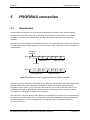
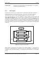
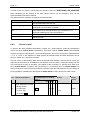
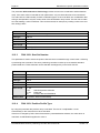
In both example projects, the same actual value data are transmitted from the slave to the master.
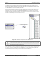
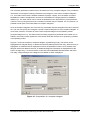
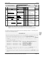
Thus, the same response telegram 0 has to be configured for both reception telegrams (0 and 1) at
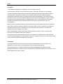
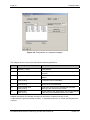
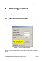
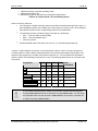
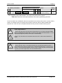
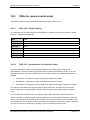
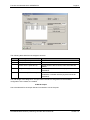
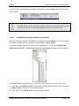
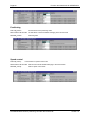
the servo positioning controller end. The following screenshot shows the necessary parameterisation
for the example project. An additional diagnostic information is displayed above the button „Change
entry“ if a communication could have been established between Master and Slave. The really
configured length of the telegram from Master to Slave is displayed.
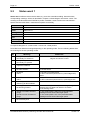
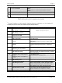
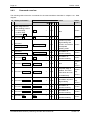
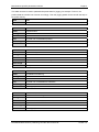
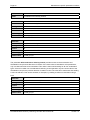
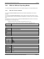
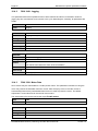
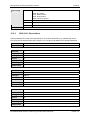
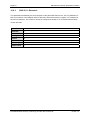
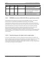
The following table describes the telegram structure:
Addres
s
Content (parameter number)
Description
0
Identifier (= 0xF0)
Fixed identifier
1
Operating mode (PNU 1500 0)
Current operating mode of the servo positioning
controller
2
Status word 1 (PNU 968 0)
Control word for device control, has to be under this
address
4
Position Actual Value
(PNU 1100 0)
Actual position, indication with the physical position unit
set for PROFIBUS
8
Velocity Actual Value
(PNU 1101 0)
Actual speed value, indication with the physical speed
unit set for PROFIBUS
12
Current actual value
(PNU 1102 0)
Actual value of the current, indicated per thousand
referring to the nominal motor current
16
Digital inputs
(PNU 1141 0)
Current status of the digital inputs, see for the meaning
of the bits in the detailed description of the PNU.
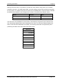
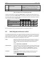
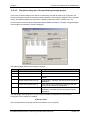
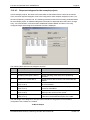
The total length of this telegram is 20 bytes. When the slave is integrated into the hardware
configuration of the master, the module:
10 Words Output
PROFIBUS-Manual Servo positioning controller DIS-2 48/10 FB
Version 1.0