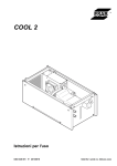
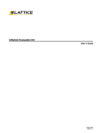
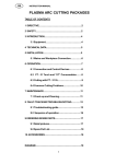
1
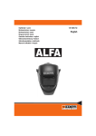
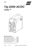
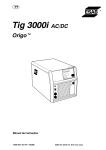
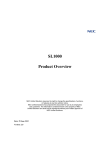
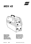
GB Aristo MechTig C2002i Instruction manual 0444 620 101 GB 110120 Valid for serial no. 810-xxx-xxxx, 049-xxx-xxxx 1 DIRECTIVE . . . . . . . . . . . . . . . . . . . . . . . . . . . . . . . . . . . . . . . . . . . . . . . . . . . . . . . . 2 SAFETY . . . . . . . . . . . . . . . . . . . . . . . . . . . . . . . . . . . . . . . . . . . . . . . . . . . . . . . . . . . 3 INTRODUCTION . . . . . . . . . . . . . . . . . . . . . . . . . . . . . . . . . . . . . . . . . . . . . . . . . . . 3.1 3.2 3 3 5 Equipment . . . . . . . . . . . . . . . . . . . . . . . . . . . . . . . . . . . . . . . . . . . . . . . . . . . . . . . . . . . . . . . . Control panel WO 100 . . . . . . . . . . . . . . . . . . . . . . . . . . . . . . . . . . . . . . . . . . . . . . . . . . . . . 5 5 4 TECHNICAL DATA . . . . . . . . . . . . . . . . . . . . . . . . . . . . . . . . . . . . . . . . . . . . . . . . . 5 INSTALLATION . . . . . . . . . . . . . . . . . . . . . . . . . . . . . . . . . . . . . . . . . . . . . . . . . . . . 6 7 5.1 5.2 5.3 5.4 Lifting instructions . . . . . . . . . . . . . . . . . . . . . . . . . . . . . . . . . . . . . . . . . . . . . . . . . . . . . . . . . Location . . . . . . . . . . . . . . . . . . . . . . . . . . . . . . . . . . . . . . . . . . . . . . . . . . . . . . . . . . . . . . . . . . Mains power supply . . . . . . . . . . . . . . . . . . . . . . . . . . . . . . . . . . . . . . . . . . . . . . . . . . . . . . . . Connecting the terminating resistor . . . . . . . . . . . . . . . . . . . . . . . . . . . . . . . . . . . . . . . . . . 7 7 7 8 6 OPERATION . . . . . . . . . . . . . . . . . . . . . . . . . . . . . . . . . . . . . . . . . . . . . . . . . . . . . . . 8 6.1 6.2 6.3 6.4 6.5 6.6 6.7 6.8 Connections and control devices . . . . . . . . . . . . . . . . . . . . . . . . . . . . . . . . . . . . . . . . . . . . Gas flow meter . . . . . . . . . . . . . . . . . . . . . . . . . . . . . . . . . . . . . . . . . . . . . . . . . . . . . . . . . . . . USB connection . . . . . . . . . . . . . . . . . . . . . . . . . . . . . . . . . . . . . . . . . . . . . . . . . . . . . . . . . . . Water connection . . . . . . . . . . . . . . . . . . . . . . . . . . . . . . . . . . . . . . . . . . . . . . . . . . . . . . . . . . Overheating protection . . . . . . . . . . . . . . . . . . . . . . . . . . . . . . . . . . . . . . . . . . . . . . . . . . . . . Flow guard, water . . . . . . . . . . . . . . . . . . . . . . . . . . . . . . . . . . . . . . . . . . . . . . . . . . . . . . . . . Flow guard, gas . . . . . . . . . . . . . . . . . . . . . . . . . . . . . . . . . . . . . . . . . . . . . . . . . . . . . . . . . . . Symbol explanations . . . . . . . . . . . . . . . . . . . . . . . . . . . . . . . . . . . . . . . . . . . . . . . . . . . . . . . 8 9 9 9 9 9 9 10 7 MAINTENANCE . . . . . . . . . . . . . . . . . . . . . . . . . . . . . . . . . . . . . . . . . . . . . . . . . . . . 10 7.1 7.2 7.3 Inspection and cleaning . . . . . . . . . . . . . . . . . . . . . . . . . . . . . . . . . . . . . . . . . . . . . . . . . . . . Topping up the coolant . . . . . . . . . . . . . . . . . . . . . . . . . . . . . . . . . . . . . . . . . . . . . . . . . . . . . Printer . . . . . . . . . . . . . . . . . . . . . . . . . . . . . . . . . . . . . . . . . . . . . . . . . . . . . . . . . . . . . . . . . . . 10 11 11 8 FAULT-TRACING . . . . . . . . . . . . . . . . . . . . . . . . . . . . . . . . . . . . . . . . . . . . . . . . . . 9 ORDERING SPARE PARTS . . . . . . . . . . . . . . . . . . . . . . . . . . . . . . . . . . . . . . . . . DIAGRAM . . . . . . . . . . . . . . . . . . . . . . . . . . . . . . . . . . . . . . . . . . . . . . . . . . . . . . . . . . . . PUMP DATA . . . . . . . . . . . . . . . . . . . . . . . . . . . . . . . . . . . . . . . . . . . . . . . . . . . . . . . . . . COOLING CARACTERISTIC . . . . . . . . . . . . . . . . . . . . . . . . . . . . . . . . . . . . . . . . . . . ORDERING NUMBER . . . . . . . . . . . . . . . . . . . . . . . . . . . . . . . . . . . . . . . . . . . . . . . . . ACCESSORIES . . . . . . . . . . . . . . . . . . . . . . . . . . . . . . . . . . . . . . . . . . . . . . . . . . . . . . . 12 12 14 18 19 20 21 Rights reserved to alter specifications without notice. TOCe -2- GB 1 DIRECTIVE DECLARATION OF CONFORMITY ESAB AB, Welding Equipment, SE-695 81 Laxå, Sweden, gives its unreserved guarantee that weld ing power source MechTig C2002i from serial number 810 are constructed and tested in compliance with the standard EN 60974-1 /-3 and EN 60974-10 (Class A) in accordance with the requirements of directive (2006/95/EC) and (2004/108/EEC). -------------------------------------------------------------------------------------------------------------Laxå 2008-05-20 Kent Eimbrodt Global Director Equipment and Automation 2 SAFETY Users of ESAB equipment have the ultimate responsibility for ensuring that anyone who works on or near the equipment observes all the relevant safety precautions. Safety precautions must meet the requirements that apply to this type of equipment. The following recommendations should be ob served in addition to the standard regulations that apply to the workplace. All work must be carried out by trained personnel well-acquainted with the operation of the equip ment. Incorrect operation of the equipment may lead to hazardous situations which can result in in jury to the operator and damage to the equipment. 1. Anyone who uses the equipment must be familiar with: S its operation S location of emergency stops S its function S relevant safety precautions S welding and cutting 2. The operator must ensure that: S no unauthorized person is stationed within the working area of the equipment when it is started up. S no-one is unprotected when the arc is struck 3. The workplace must: S be suitable for the purpose S be free from drafts 4. Personal safety equipment S Always wear recommended personal safety equipment, such as safety glasses, flame-proof clothing, safety gloves. Note! Do not use safety gloves when replacing wire. S Do not wear loose-fitting items, such as scarves, bracelets, rings, etc., which could become trapped or cause burns. 5. General precautions S Make sure the return cable is connected securely. S Work on high voltage equipment may only be carried out by a qualified electrician. S Appropriate fire extinquishing equipment must be clearly marked and close at hand. S Lubrication and maintenance must not be carried out on the equipment during operation. -3dp02d1ea GB WARNING Arc welding and cutting can be injurious to yourself and others. Take precausions when welding and cutting. Ask for your employer's safety practices which should be based on manufacturers' hazard data. ELECTRIC SHOCK - Can kill S Install and earth the unit in accordance with applicable standards. S Do not touch live electrical parts or electrodes with bare skin, wet gloves or wet clothing. S Insulate yourself from earth and the workpiece. S Ensure your working stance is safe. FUMES AND GASES - Can be dangerous to health S Keep your head out of the fumes. S Use ventilation, extraction at the arc, or both, to take fumes and gases away from your breathing zone and the general area. ARC RAYS - Can injure eyes and burn skin. S Protect your eyes and body. Use the correct welding screen and filter lens and wear protective clothing. S Protect bystanders with suitable screens or curtains. FIRE HAZARD S Sparks (spatter) can cause fire. Make sure therefore that there are no inflammable materials nearby. NOISE - Excessive noise can damage hearing S Protect your ears. Use earmuffs or other hearing protection. S Warn bystanders of the risk. MALFUNCTION - Call for expert assistance in the event of malfunction. Read and understand the instruction manual before installing or operating. PROTECT YOURSELF AND OTHERS! WARNING Do not use the power source for thawing frozen pipes. CAUTION Class A equipment is not intended for use in residential locations where the electrical power is provided by the public low-voltage supply system. There may be potential difficulties in ensuring electromagnetic compatibility of class A equipment in those locations, due to conducted as well as radiated disturbances. CAUTION This product is solely intended for arc welding. -4dp02d1ea GB Dispose of electronic equipment at the recycling facility! In observance of European Directive 2002/96/EC on Waste Electrical and Electronic Equipment and its implementation in accordance with national law, electrical and/or electronic equipment that has reached the end of its life must be disposed of at a recycling facility. As the person responsible for the equipment, it is your responsibility to obtain information on approved collection stations. For further information contact the nearest ESAB dealer. CAUTION Read and understand the instruction manual before installing or operating. ESAB can provide you with all necessary welding protection and accessories. 3 INTRODUCTION MechTig C2002i is a welding power source intended for mechanized TIG welding. ESAB's accessories for the product can be found on page 21. 3.1 Equipment The power source is supplied with: S instruction manual for the welding power source S instruction manual for the control panel S 5 m return cable S terminating resistor. 3.2 Control panel WO 100 See the separate instruction manual for a detailed description of the control panel. -5dp02d1ea GB 4 TECHNICAL DATA MechTig C2002i Mains voltage 230 V $10%, 1 50/60 Hz Mains supply Primary current Imax Zmax 0.35 Ω 22 A Setting range 5 A - 200 A Permitted load 30% duty cycle 35% duty cycle 60 % duty cycle 100% duty cycle 200 A / 18 V 180 A / 17 V 150 A / 16 V 110 A / 14 V Power factor at maximum current 0.98 Efficiency at maximum current 73 % Open-circuit voltage 92 V Operating temperature -10 to +40° C Transportation temperature -20 to + 55° C Constant A-weighted sound pressure < 70 dB Dimensions l x w x h 470 x 479 x 472 mm Weight 30 kg Enclosure class Application class IP 23 Cooling unit Cooling power at 50 Hz at 60 Hz 670 W at 40° C temp. difference and flow 1.0 l/min 650 W at 40° C temp. difference and flow 1.0 l/min Type of cooling 50 % water / 50% monoethylene glycol Coolant quantity 2.0 l Maximum water flow at 50 Hz at 60 Hz 1.22 l/min 1.44 l/min Maximum water pressure at 50 Hz at 60 Hz 0.32 MPa (3.2 bar) 0.42 MPa (4.2 bar) Mains supply, Zmax Maximum permissible line impedance of the network in accordance with IEC 61000-3-11. Duty cycle The duty cycle refers to the time as a percentage of a ten-minute period that you can weld or cut at a certain load without overloading. The duty cycle is valid for 40° C. The duty cycle is valid for 40° C. Enclosure class The IP code indicates the enclosure class, i. e. the degree of protection against penetration by solid objects or water. Equipment marked IP23 is designed for indoor and outdoor use. Application class The symbol indicates that the power source is designed for use in areas with increased electrical hazard. -6dp02d1ea GB 5 INSTALLATION The installation must be executed by a professional. Note Mains supply requirements High power equipment may, due to the primary current drawn from the mains supply, influence the power quality of the grid. Therefore connection restrictions or requirements regarding the maximum permissible mains impedance or the required minimum supply capacity at the interface point to the public grid may apply for some types of equipment (see technical data). In this case it is the responsibility of the installer or user of the equipment to ensure, by consultation with the distrubution network operator if necessary, that the equipment may be connected. 5.1 Lifting instructions 5.2 Location Position the welding power source such that its cooling air inlets and outlets are not obstructed. 5.3 Mains power supply Make sure that the welding power source is connected to the correct supply voltage and that it is protected by the correct fuse rating. A protective earth connection must be made in accordance with regulations. Recommended fuse sizes and minimum cable area MechTig C2002i Mains voltage Mains cable area Phase current I RMS Fuse anti-surge type C MCB 230 V 1 50/60 Hz 3 G 2.5 mm2 12 A 16 A 16 A Welding cable area 50 mm2 NOTE! The mains cable areas and fuse sizes as shown above are in accordance with Swedish regulations. Use the welding power source in accordance with the relevant national regulations. -7dp02d1ea GB 5.4 Connecting the terminating resistor To avoid communication interference, the remote socket must be fitted with a terminating resistor, when a remote control unit is not connected. 6 OPERATION General safety regulations for the handling of the equipment can be found on page 3. Read through before you start using the equipment! 6.1 Connections and control devices 1 Connection for start gas in 2 Connection for weld gas in 3 Connection for root gas in 4 Switch for mains power 5 Rating plate for connection data 6 12 13 14 Control panel, see separate instruction manual Gas flow meter Printer USB connection, see point 6.3. Connection for documentation system WMS 4000 Connection (CAN) for remote control unit, terminating resistor or welding station A25 Connection for wire feed Root gas connection out Weld and start gas connection out 15 Connection for rotation 16 Connection for coolant from tube welding tool RED 17 Connection with ELP* for coolant to the tube welding tool BLUE 18 Topping up with coolant 19 Connection for welding current (-) 20 Connection for manual TIG torch 21 Return cable connection (+) 7 8 9 10 11 *ELP = ESAB Logic Pump, see point 6.4. -8dp02d1ea GB 6.2 Gas flow meter NOTE! To achieve the correct flow, the flow must be measured at the tool. The flow meter is calibrated for Argon gas at 4 bar pressure. The gas flow obtained from the tool can vary depending on the connected tool. If other pressures or gases are used, the gas flow must be measured at the workpiece. ESAB recommends that a pressure regulator set for 4 bar is used. 6.3 USB connection The external USB memory can be used to transfer programs to and from systems. Note! During normal use there is no risk of ”viruses” ”infecting” equipment. To eliminate the risk entirely, we recommend that the memory, which is used together with this equipment, not be used for any other purpose other than its intended. Certain USB memories may not work with this equipment. We recommend using USB memories from a reputable supplier. ESAB assumes no responsibility for any damage caused as a consequence of incorrect use of the USB memory. 6.4 Water connection The power source is equipped with a detection system ELP (ESAB Logic Pump) which checks that the water hoses are connected. When connecting a water-cooled tube welding tool, the water pump starts. 6.5 Overheating protection The welding power source has overheating protection that operates if the temperature becomes too high. When this occurs, the welding current is interrupted and a red flashing field with the text ”OVERHEAT” appears in the lower right-hand corner of the control panel. When the temperature drops, the overheat protection is automatically reset and the field stops flashing red. For further information see the control panel user manual. 6.6 Flow guard, water The water flow guard blocks the power source if the coolant stops (minimum water flow 0.7 l/min). When this occurs the welding current is interrupted and an error message is shown on the control panel. For further information see the control panel user manual. 6.7 Flow guard, gas The flow guard stops the welding process if the gas flow falls below 4 l/min. When this occurs an error message appears on the control panel. For further information see the control panel user manual. -9dp02d1ea GB 6.8 Symbol explanations TIG-torch Start and weld gas out Tube welding tool Root gas out Rotation Root gas in Wire feed Weld gas in Start gas in For detailed description of the function see instruction manual for the control panel. 7 MAINTENANCE Regular maintenance is important for safe, reliable operation. Only those persons who have appropriate electrical knowledge (authorized personnel) may remove the safety plates. CAUTION All guarantee undertakings from the supplier cease to apply if the customer himself attempts any work in the product during the guarantee period in order to rectify any faults. 7.1 Inspection and cleaning Power source Check regularly that the welding power source is not clogged with dirt. How often and which cleaning methods apply depend on: S welding process S arc time S placement S surrounding environment. It is normally sufficient to blow down the power source with dry compressed air (reduced pressure) once a year. Clogged or blocked air inlets and outlets can cause overheating. - 10 dp02d1ea GB Tube welding tool The tube welding tool's wear parts should be cleaned and replaced at regular intervals in order to achieve trouble-free welding. 7.2 Topping up the coolant Top up with coolant to the level of the filling hole. ESAB's refrigerant is recommended for use. See accessories on page 21. CAUTION The coolant must be handled as chemical waste. 7.3 Printer Changing the paper roll To change the paper roll, proceed as described below: 1. Open the printer cover as shown in the figure. 2. Position the paper roll making sure it unrolls in the proper direction as shown in the figure. Opening the printer cover Positioning the paper roll - 11 dp02d1ea GB 3. Pull out the paper and close the cover, as shown in the figure. 4. The printer is ready to print. Closing the printer cover 8 Ready to print FAULT-TRACING Try these recommended checks and inspections before sending for an authorised service technician. Type of fault Corrective action S S No arc. S S S The welding current is interrupted during welding. S S S Check that the mains power supply switch is turned on. Check that the welding current supply and return cables are correctly connected. Check that the correct current value is set. Check the coolant flow. Check the coolant level. Check whether the overheating protection has operated (fault code 6 2 is displayed on the control panel). Check the coolant flow. Check the mains power supply fuses. The overheating protection trips frequently. S Make sure that you are not exceeding the rated data for the welding power source (i.e. that the unit is not being overloaded). Poor welding performance. S Check that the welding current supply and return cables are correctly connected. Check that the correct current value is set. Check that the correct electrodes are being used. Check the mains power supply fuses. Check that the correct welding gas is being used. S S S S 9 ORDERING SPARE PARTS MechTig C2002i is designed and tested in accordance with the international and Euro pean standards 60974-1, 60974-2, 60974-3 and 60974-10 . It is the obligation of the ser vice unit which has carried out the service or repair work to make sure that the product still conforms to the said standard. Spare parts may be ordered through your nearest ESAB dealer, see the last page of this publication. - 12 dp02d1ea - 13 p Diagram - 14 dp02e Edition 110120 - 15 dp02e Edition 110120 - 16 dp02e Edition 110120 - 17 dp02e Edition 110120 Pump data P = Pump pressure Q = Flow rate - 18 dp02k Cooling caracteristic P = Power tö = Flow rate - 19 dp02k MechTig C2002i Ordering number Ordering no. Denomination Type 0444 700 880 Welding power source Aristot MechTig C2002i, WO100 0459 839 009 Spare parts list Aristot MechTig C2002i, WO100 0444 536 Instruction manual Control panel WO100 Instruction manuals and the spare parts list are available on the Internet at www.esab.com - 20 dp02o Edition 110120 MechTig C2002i Accessories Thermal paper . . . . . . . . . . . . . . . . . . . . . . . . . . . . . . . 0444 529 002 Coolant (ready mixed) 50 % water and 50% monoethylene glycol (10 l) . . . 0007 810 012 Carriage . . . . . . . . . . . . . . . . . . . . . . . . . . . . . . . . . . . . 0301 100 880 - 21 dp02a Edition 110120 MechTig C2002i Product Ordering number Tube welding tool PRB 17-49 watercooled . . . . . . . . . . . . . . . . . . . . . . . . . . . . . . . . . . . . 33-90 watercooled . . . . . . . . . . . . . . . . . . . . . . . . . . . . . . . . . . . . 60-170 watercooled . . . . . . . . . . . . . . . . . . . . . . . . . . . . . . . . . . . 17-49 aircooled . . . . . . . . . . . . . . . . . . . . . . . . . . . . . . . . . . . . . . . 33-90 aircooled . . . . . . . . . . . . . . . . . . . . . . . . . . . . . . . . . . . . . . . 60-170 aircooled . . . . . . . . . . . . . . . . . . . . . . . . . . . . . . . . . . . . . 0443 750 882 0443 760 882 0443 770 882 0443 750 883 0443 760 883 0443 770 883 Tube welding tool PRD 160 (for meltwelding with floating head) . . . . . . . . . . . . . . . . . 160 with wire feeder . . . . . . . . . . . . . . . . . . . . . . . . . . . . . . . . . . . 0444 151 880 0444 151 881 Tube welding tool 3-12 enclosed 3-38 enclosed 6-76 enclosed 0444 300 880 0444 301 880 0444 302 880 PRH ........................... ........................... ........................... Tube welding tool POC 12-60 with wire feed unit . . . . . . . . . . . . . 0443 930 880 TIG hand torch TXH 400W (4 m OKC) . . . . . . . . . . . . . . . . . . . . . . 0460 014 840 Wire feed unit MEI 10 for PRB 17-49 . . . . . . . . . . . . . . . . . . . . . . . . . . . for PRB 33-90 . . . . . . . . . . . . . . . . . . . . . . . . . . . for PRB 60-170 . . . . . . . . . . . . . . . . . . . . . . . . . . . . . . . . . . . . . . . 0444 211 880 0444 212 880 0444 213 880 Wire feed unit MEI 21 . . . . . . . . . . . . . . . . . . . . . . . . . . . . . . . . . . . . . 0443 830 880 Remote control unit MechT1 CAN . . . . . . . . . . . . . . . . . . . . . . . . . . 0460 181 880 Remote cable CAN 4 pole - 12 pole, 5m ................................................. 10 m . . . . . . . . . . . . . . . . . . . . . . . . . . . . . . . . . . . . . . . . . . . . . . . . 15 m . . . . . . . . . . . . . . . . . . . . . . . . . . . . . . . . . . . . . . . . . . . . . . . . 25 m . . . . . . . . . . . . . . . . . . . . . . . . . . . . . . . . . . . . . . . . . . . . . . . . 0.25 m . . . . . . . . . . . . . . . . . . . . . . . . . . . . . . . . . . . . . . . . . . . . . . . 0459 554 880 0459 554 881 0459 554 882 0459 554 883 0459 554 884 Documentation system Welddoct WMS 40000 . . . . . . . . . . . . . . . . . . . . . . . . . . . . . . . . SPS 4000 . . . . . . . . . . . . . . . . . . . . . . . . . . . . . . . . . . . . . . . . . . . . Opto cable, 15 m . . . . . . . . . . . . . . . . . . . . . . . . . . . . . . . . . . . . . . Opto cable, 2 m . . . . . . . . . . . . . . . . . . . . . . . . . . . . . . . . . . . . . . . 0457 410 880 0457 410 881 0457 072 881 0457 072 882 Return cable 4,5 m, 25 mm2 . . . . . . . . . . . . . . . . . . . . . . . . . . . . . . . 0156 743 909 Extension cable for wire feed unit and CAN 42 V, 10 m . . . . . . . . . . . . . . . . . . . for rotation, 10 m . . . . . . . . . . . . . . . . . . . . . . . . . . . . . . . . . . . . . . Extension set for current, water and gas, 8 m . . . . . . . . . . . . . . . . . . . . . . . . . . for current, water, gas and torch contact, 8 m . . . . . . . . . . . . . - 22 dp02a 0456 904 880 0456 906 880 0456 905 880 0466 705 881 Edition 110120 MechTig C2002i - 23 dp02a Edition 110120 ESAB subsidiaries and representative offices Europe AUSTRIA ESAB Ges.m.b.H Vienna-Liesing Tel: +43 1 888 25 11 Fax: +43 1 888 25 11 85 BELGIUM S.A. ESAB N.V. Brussels Tel: +32 2 745 11 00 Fax: +32 2 745 11 28 NORWAY AS ESAB Larvik Tel: +47 33 12 10 00 Fax: +47 33 11 52 03 POLAND ESAB Sp.zo.o. Katowice Tel: +48 32 351 11 00 Fax: +48 32 351 11 20 BULGARIA ESAB Kft Representative Office Sofia Tel/Fax: +359 2 974 42 88 PORTUGAL ESAB Lda Lisbon Tel: +351 8 310 960 Fax: +351 1 859 1277 THE CZECH REPUBLIC ESAB VAMBERK s.r.o. Vamberk Tel: +420 2 819 40 885 Fax: +420 2 819 40 120 ROMANIA ESAB Romania Trading SRL Bucharest Tel: +40 316 900 600 Fax: +40 316 900 601 DENMARK Aktieselskabet ESAB Herlev Tel: +45 36 30 01 11 Fax: +45 36 30 40 03 RUSSIA LLC ESAB Moscow Tel: +7 (495) 663 20 08 Fax: +7 (495) 663 20 09 FINLAND ESAB Oy Helsinki Tel: +358 9 547 761 Fax: +358 9 547 77 71 SLOVAKIA ESAB Slovakia s.r.o. Bratislava Tel: +421 7 44 88 24 26 Fax: +421 7 44 88 87 41 FRANCE ESAB France S.A. Cergy Pontoise Tel: +33 1 30 75 55 00 Fax: +33 1 30 75 55 24 SPAIN ESAB Ibérica S.A. Alcalá de Henares (MADRID) Tel: +34 91 878 3600 Fax: +34 91 802 3461 GERMANY ESAB GmbH Solingen Tel: +49 212 298 0 Fax: +49 212 298 218 SWEDEN ESAB Sverige AB Gothenburg Tel: +46 31 50 95 00 Fax: +46 31 50 92 22 GREAT BRITAIN ESAB Group (UK) Ltd Waltham Cross Tel: +44 1992 76 85 15 Fax: +44 1992 71 58 03 ESAB international AB Gothenburg Tel: +46 31 50 90 00 Fax: +46 31 50 93 60 ESAB Automation Ltd Andover Tel: +44 1264 33 22 33 Fax: +44 1264 33 20 74 SWITZERLAND ESAB AG Dietikon Tel: +41 1 741 25 25 Fax: +41 1 740 30 55 HUNGARY ESAB Kft Budapest Tel: +36 1 20 44 182 Fax: +36 1 20 44 186 UKRAINE ESAB Ukraine LLC Kiev Tel: +38 (044) 501 23 24 Fax: +38 (044) 575 21 88 ITALY ESAB Saldatura S.p.A. Mesero (Mi) Tel: +39 02 97 96 81 Fax: +39 02 97 28 91 81 North and South America ARGENTINA CONARCO Buenos Aires Tel: +54 11 4 753 4039 Fax: +54 11 4 753 6313 BRAZIL ESAB S.A. Contagem-MG Tel: +55 31 2191 4333 Fax: +55 31 2191 4440 CANADA ESAB Group Canada Inc. Missisauga, Ontario Tel: +1 905 670 02 20 Fax: +1 905 670 48 79 MEXICO ESAB Mexico S.A. Monterrey Tel: +52 8 350 5959 Fax: +52 8 350 7554 USA ESAB Welding & Cutting Products Florence, SC Tel: +1 843 669 44 11 Fax: +1 843 664 57 48 Asia/Pacific SOUTH KOREA ESAB SeAH Corporation Kyungnam Tel: +82 55 269 8170 Fax: +82 55 289 8864 UNITED ARAB EMIRATES ESAB Middle East FZE Dubai Tel: +971 4 887 21 11 Fax: +971 4 887 22 63 Africa EGYPT ESAB Egypt Dokki-Cairo Tel: +20 2 390 96 69 Fax: +20 2 393 32 13 SOUTH AFRICA ESAB Africa Welding & Cutting Ltd Durbanvill 7570 - Cape Town Tel: +27 (0)21 975 8924 Distributors For addresses and phone numbers to our distributors in other countries, please visit our home page www.esab.com CHINA Shanghai ESAB A/P Shanghai Tel: +86 21 2326 3000 Fax: +86 21 6566 6622 INDIA ESAB India Ltd Calcutta Tel: +91 33 478 45 17 Fax: +91 33 468 18 80 INDONESIA P.T. ESABindo Pratama Jakarta Tel: +62 21 460 0188 Fax: +62 21 461 2929 JAPAN ESAB Japan Tokyo Tel: +81 45 670 7073 Fax: +81 45 670 7001 MALAYSIA ESAB (Malaysia) Snd Bhd USJ Tel: +603 8023 7835 Fax: +603 8023 0225 SINGAPORE ESAB Asia/Pacific Pte Ltd Singapore Tel: +65 6861 43 22 Fax: +65 6861 31 95 THE NETHERLANDS ESAB Nederland B.V. Amersfoort Tel: +31 33 422 35 55 Fax: +31 33 422 35 44 ESAB AB SE-695 81 LAXÅ SWEDEN Phone +46 584 81 000 www.esab.com 101217