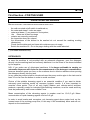
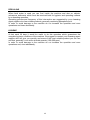
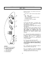
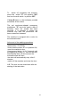
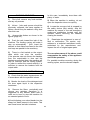
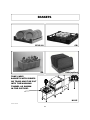
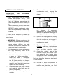
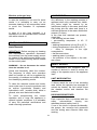
1
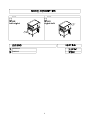
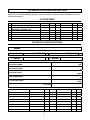
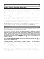
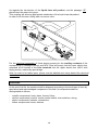
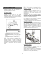
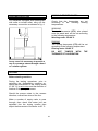
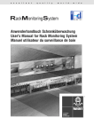
DISHWASHERS WITH PULL-THROUGH RACK M115 INSTRUCTIONS MANUAL R06/2012 DECLARATION OF CONFORMITY The following : LAMBER snc di Affaba F. e C. – Via Italia 6 – 26855 Lodi Vecchio (LO) ITALY Declare under our responsibility that: Apparatus: DISHWASHER WITH PULL THROUGH RACK Trademark: LAMBER Manufacturer : LAMBER mod. M115 / M115-AS matr…………….. for which this declaration refers to the conformity of the following standards: Safety of household and electrical appliances - General requirements EN60335-1(2002) + A1/A11(2004), A12 (2006) + A2 (2006) + + A13 (2008) + A14 (2010) + A15 (2011) Safety of household and electrical appliances - Part 2^ Particular requirements for commercial electric dishwashing machines EN60335-2-58 (2005) + A1 (2008) + A11 (2010). Household and similar electrical appliances – Electromagnetic fields – Measurement methods for electromagnetic fields of household appliances and similar apparatus with regard to human exposure EN 62233:(2008) Limits and methods of measurement of radio disturbance characteristics of electrical motor-operated and thermal appliances for households and similar purposes, electric tools and similar electric apparatus - EN 55014-1–1(2006) + A1 (2009) Limits for harmonic current emissions (equipment input current 16 A per phase) - EN 61000-3-2(2006) or >16A and 75A + A2 (2005) EN 61000-3-12(2005) Limitation of voltage fluctuations and flicker in low-voltage supply systems for equipment with rated current 16 A. EN 61000-33(2008) o >16A e 75A EN 61000-3-11(2000) Immunity requirements for household appliances, tools and similar apparatus. Product family standard EN 55014-2(1997) + A1(2001) + A2 (2008) Safety of machinery Basic concepts, general principles for design - Basic terminology, methodology-ISO 12100-1 (2009). Safety of machinery - Basic concepts, general principles for design - Technical principles-ISO 12100-2 (2009). on the basis of what is foreseen by the Directives: 2004/108/CE, 2006/42/CE. 2004/108/EC, 2006/42/EC. We decline any responsability for injuries or damage derived from machine misuse, abuse by others or improper machine maintenance or repairs. (date) li 01/01/2013 The administrator technical file case manager : Ing Roberto Affaba address : via italia 6 – 26855 – Lodi Vecchio (LO) Italy WASTE OF ELECTRICAL AND ELECTRONIC EQUIPMENT DIRECTIVE (WEEE,RAEE in Italy) 2002/96/EC AND SUBSEQUENT 2003/108/EC The marking shown below indicates that the product cannot be disposed of as part of normal household waste. Electrical and Electronic Equipment (EEE) can contain materials harmful to health and the environment, and therefore is subject to separate waste collection: it must be disposed of at appropriate waste collection points or returned to the distributor against purchase of new equipment of similar type or having the same functions. The directive mentioned above, to which make reference for further details, provides for punitive actions in case of illegal disposal of such waste. LAMBER, manufacturer of this equipment, is enrolled in the Italian WEEE Register – the Register of Producers of Electrical and Electronic Equipment- from the 18th /02/2008 with the number IT08020000000617. 4 MO DE L MODE L M115 left-right M115 right-left WASHING RINSING 5 TECHNICAL DATA AND DESCRIPTION The table reported at page 5 shows the basic models of conveyor dishwashers and identifies the single washing areas to which additional modules can be added to improve their performance. ACCESSORIES COLD PRE-WASHING STEAM CONDENSER - CVM DRYING – AS ADDITIONAL RINSING - RIS HEAT RECOVERER – RC-CVM AUTOTIMER SPLASH SHIELD (PMC-PMA-PMA/R) BOOSTER PUMP fan fan kW kW fan kW Motor kW Heat element kW TECHNICAL SPECIFICATIONS Model: version Left-Right 1st speed baskets/hour Right-Left 2nd speed ELECTRIC POWER baskets/hour kW ELECTRICAL INPUT A ELECTRIC CABLE mm2 CIRCUIT BREAKER A lcc ELECTRIC INPUT 6 kA VOLTAGE PRE-WASHING TANK ELEMENTS kW ELECTRIC PUMP kW FIRST WASHING TANK ELEMENTS kW ELECTRIC PUMP kW SECOND WASHING TANK ELEMENTS kW ELECTRIC PUMP kW THIRD WASHING TANK ELEMENTS kW ELECTRIC PUMP kW PRE-RINSING TANK ELEMENTS kW ELECTRIC PUMP kW RINSING BOILER ELEMENT kW BOILER ELEMENT kW kW GEARED MOTOR 6 DESCRIPTION CHARACTERISTICS * Body and tank in stainless steel construction 18/10 AISI 304, * Tunnel composition: - 1 Wash - wash arms : 3 upper + 2 lower - 1 Rinse - rinse arms : 1 upper + 1 lower * Completely automatic, * Upper and lower fixed washing ( 55÷60 °C ) * Upper and lower fixed rinsing ( 85-90 °C ) * Washing and rinsing arms in stainless steel constructions, easy and interchangeable, * Double skin with thermic and acoustic insulation ; * Slanted tank with rounded edges, * Stainless steel autodraining washing pump, * Counterbalanced door * Front panel composition :: - Main ON/OFF switch; - Start pushbutton - Stop pushbutton - Emergency pushbutton - Machine ON indicator - Machine ready indicator - Overload cutout indicator * Frontal maintenance * Automatic tank loading * Rinse economizer * Tank and pump filters * Insulated Boiler SAFETY * Feet adjustable and strong * Pressure-switch protection for Heating elements * Thermic protection for washing pump * Automatic stopping of pull-through in case of foreign bodies * Low voltage control circuit (24V) for greater safety during work operation * Dishes (Stop with End Micro-switch on the exit table) * Door opening safety device 7 disassembly Contents General norms page 09 Introduction and safety norms page 10 Unpacking and delivery checks page 12 1 – INSTRUCTIONS FOR THE USER page 13 First section - For the user – Operation before washing page 14 Switch-on and use of the dishwashing machine mod. M115 page 16 Washing of dishes – During washing operations page 18 After washing operations page 20 Helpful suggestions - Achievements page 21 Safety devices page 21 Washing flow control system page 23 Useful hints of stainless steel maintenance page 24 2 – INSTRUCTIONS FOR THE INSTALLER page 25 Installation page 26 Second section - For the installer - Disposal page 27 Positioning – Electrical connection page 29 Water connections page 30 Water draining - Steam feeding – page 31 Steam exhaust – Vapours suction – Testing - Working temperatures page 32 Torque limiter page 33 Steam condenser - Autotimer page 34 Possible drawbacks – causes - remedies page 35 Table connection scheme page 41 Wiring diagram page 42 8 INSTRUCTIONS MANUAL DISHWASHING MACHINE M115 The automatic-rack conveyor dishwashing machines of the M115 series are designed to wash any kinds of dishes . The modular system and the various optionals available allow the make-up of dishwashing machines with the most appropriate features in order to meet your production,space saving and energy-saving requirements. GENERAL NORMS ENGLISH Tank You for purchasing our Dishwashing Machine. Perfect washing-up results as far as hygiene concerns and a correct operation of the dishwashing machine can be assured only in case the instructions reported in the present manual are carefully followed. We hope the information reported in the present manual will be helpful to You. They are based on data and our best updated knowledge. Carefully read the Instructions reported in the manual, recommendations and suggestions included. Carefully read the terms of sale too, the ones limiting warranty included. 9 INTRODUCTION AND SAFETY NORMS INTRODUCTION This equipment is destined only to the use it has been conceived for: tableware washing such as dishes, glasses, cups, cutlery, trays, etc. Using it to wash machine components or objects whose dimensions are superior to the machine working passage is improper and therefore dangerous. - The noise of the machine running empty, measured at the working positions (fig. 1) and at 1.6m from the floor, is the following: Leq A Level equivalent of sound pressure dB(A) position 1 position 2 position 3 70 68 70 The level of peak sound pressure Lpc is not declared as it is much inferior to 130dB(C): PRELIMINARY OBSERVATION Carefully read the instructions reported in the present user manual, as it gives important indications about safety of installation, operation and maintenance: - carefully keep the present manual for further consultations; the illustrations and drawings showing the machine are intended for general reference only and are not necessarily accurate in every particular; - the dimensions and characteristics of the machine, given in this Manual, are not to be considered binding and may be changed without prior notice; - having removed the packing material, check that all the equipment is present. If there is any doubt, do not use it and contact qualified personnel. The packing elements (plastic bags, nails, etc.) should be kept away from children, because they are dangerous. 10 GENERAL SAFETY REGULATIONS THIS SAFETY CODE HAS BEEN COMPILED IN YOUR INTEREST. Strict adherence to these rules will reduce the risks of injury both to yourself and to others; Personnel working with this machine must adhere strictly to all statutory safety regulations as well as the specific rules listed below. Failure to do so may result in personal inyury and damage to the machine; DO NOT attempt to move, install, set-up or operate this machine until you have read and fully understood this Manual. If doubt persists, ask your supervisor; never leave tools, parts or other loose material on or in the machine; Before switching the equipment the equipment on, make sure that the model plate data conforms to that of the electrical and water distribution network; remember that even with the mains isolator in the “OFF” position, the incoming cables are still live; BEFORE starting machine o cycle, after any maintenance or repair work, make sure all protective are correctly installed; be vigilant at all times, remember that your safety and that of your fellow workers depend on you; when moving or lifting the machine, care must be taken to comply with all the relevant regulations governing such operations; installation should be carried out by qualified personnel according to the manufacturer's instructions. this equipment should be destined to the use which it has been conceived for. Any other application should be considered improper and consequently dangerous; the equipment should only be used by personnel trained for its use; SPECIAL SAFETY REGULATIONS - - adjustement and repairs must be carried out only by personnel qualified. Repair carried out by unskilled personnel may be dangerous; perfect washing-up results as far as hygiene concerns and a correct operation of the washing machine can be assured only in case the instructions reported in the present handbook are carefully followed; the machine must be only used by authorized personnel which must comply with sanitary measures; do not leave the machine in environment with temperatures inferior to 0°C; the machine protection degree is IP55 for Control board and IP32 for machine, therefore it should not be washed with direct high pressure jets of water; If the power cable is defective, it must be replaced by your manufacturer or by a technical assistance service or by a qualified technician in order to avoid risks. 11 UNPACKING AND DELIVERY CHECKS When the case with the machine has been received, unpack it as follows: - Remove the upper cover and the wooden case side walls, take care not to damage the machine, Remove possible accessories boxes, Remove the protecting cellophane, Make sure that the machine has not been damaged during transport, Make sure that all covers and panels have been correctly fixed and that no loosen part is present, Visually inspect that all electrical components are integral. TRANSPORT AND INSTALLATION - To lift and transport the machine, insert the truck forks under the frame connected to the points indicated by the yellow adhesives applied on the machine front side (see draw below). disforchem115 draw “A”* - - Before plugging the machine, make sure that the supply voltage of the domestic wiring system and the water supply from water connection corresponds to the ones reported on the rating plate Installation should be carried out by qualified personnel according to the manufacturer's indications During instalation, it is recommended to level the machine in order to ensure a correct operation. 12 INSTRUCTIONS FOR THE USER M115 First Section - FOR THE USER OPERATION BEFORE WORKING BEFORE STARTING - THE WORKING OPERATION BE SURE THAT: the wall-mounted on/off switch is switched on; the water and steam* cocks are open; water and steam (*) are present in the system; the filters are in their housings curtains are correctly positioned; the inspection doors are closed; the dimensions of the dishes to be washed do not exceed the washing working dimensions; Check that the detergent and rinse aid containers are not empty. Switch the machine on . Go to the page dealing with the model selected . (*) for steam machines only DETERGENTS In case the machine is not provided with an automatic dispenser, pour the detergent directly into the washing tank and uniformly distribute it on the filters in the doses indicated by the supplier. N.B.: If you make use of chlorinated sanitizers, it is always advisable to employ an automatic dispenser with feeler for the measurement of the detergent concentration, because brownish spots can form on the surfaces due to chlorine reactions when pouring the detergent directly into the tank. In any case the product shall be introduced near the pump suction pipe in the tank and at least 15 cm far from the bottom in order to avoid corrosion. Choice of the suitable cleansing agent is an essential condition if you want to obtain extremely good washing results as concerns hygienic results. It is then important to consider some points. First of all only highly alkaline and chlorine-active antifoam products, especially made for industrial dish-washing machines, must be used and they must be produced by well known reliable Firms. Mean concentration of the cleansing agents in powder must be 1,5÷2,5 g/lt. Mean concentration of liquid cleansing agents nust be 2÷4 g/lt. In order to avoid scales and corrosions, put cleansing agent above water level on the nearest area of the sucking pump filter, in this way it will immediately dilute and will not deposit on the tank bottom. 14 DESCALING When hard water is used you can find, inside the machine and also on objects, calcareous sediments which must be removed both for hygienic and operating reasons by a descaling operation. Operating process and frequency of this intervention are suggested by your cleansing agent supplier who has suitable products, generally containing phosphoric acid. In order to avoid damage to the machine do not increase the quantities and once operations end rinse abundantly. HYGIENE At last each 30 days it would be useful to do this operation which guarantees the complete hygienic conditions of the machine. We suggest to contact your cleansing agent supplier who will give you quantity and name of the most suitable product you can use and that, generally, is an active chloride powder (100÷200 ppm). In order to avoid damage to the machine do not increase the quantities and once operations end, rinse abundantly. 15 SWITCH-ON AND USE OF THE DISHWASHING MACHINE MOD. M115 BEFORE STARTING THE WORKING OPERATIONS MAKE SURE THAT: - the cock is open and the water doesn’t lack, - the filters are in their housings; - rinse aid and washing detergent pumps’ containers are filled. - the machine’s door is CLOSED. H I THEN PROCEED: 1) Put the wall switch in position ‘’ON’’. The displays of the washing and rinsing temperatures will light on. Then press the on/off switch "P" to start up the machine. The lamp "G" will start flashing and the tanks’ filling will automatically start. Lamp "G" lighted on indicates that the appropriate level has been reached in the tank and the heating element starts working. P 2) Wait until the washing temperature is between 55° and 60° C and the rinsing one is between 80° to 85° C. Check the temperature looking at the thermometers on the front panel . D G 3) Then press the start button “H”. The washing will start and the racks will move. Rinsing is operated automatically in correspondence with the passing through of the dishes. M 4) At this point the machine is ready to wash the dishes (see page 18) . LEGEND M – Overload cut-out indicator G - Machine ready indicator D – Machine on indicator I - Stop pushbutton H – Start pushbutton P – Switch ON/off 5) If it’s required to stop the washing operations, press the button ”I” to stop the washing pump and the rack moving. 16 To switch off completely the machine, press the switch "P" into position "Off" and turn the wall switch in position OFF. If lamp M lights on, that indicates possible anomalies at the motors. The red mushroom-shaped emergency pushbutton "P" has to be used in case of anomaly. Once the trouble has been removed, it is possible to restart the machine only after the pushbutton has been rotated and released. The machine is equipped with a valve for the automatic drain. At the end of the washing operations: -press button “I” (STOP), -check that the switch ‘P’ is in position ON, -open the machine’s door, -keep pressed button ‘H’ for 3 seconds until the lighting up of lamp ‘G’, that will fast and intermittently flash. At this moment the automatic drain will start, -the drain will automatically stop after 2 minutes, -switch off the machine and close the door. N.B. The door can be closed also after the starting of the tank drain. 17 In this case, immediately rinse them with plenty of water. WASHING OF DISHES 1) Fisrt of all, remove any food residues and any oily masses . 5) When the machine is working, do not open the inspection doors too quickly. 2) Knives , forks and spoons should be previously softened; the same applies to dishes, should they be washed a long time after their use . 6) In case the conveyor belt is stopped by the safety device (limit switch), stop the machine by means of the red emergency mushroom pushbutton located near the operator before removing the obstacle causing the trouble. 3) Arrange the dishes as shown in the figures (page 22) . 7) Deactivate the equipment in case of fault or malfunction. For repairs, only address to a technical assistance center authorised by the manufacturer and impose the use of original spare parts. 4) Push the rack toward the inlet of the machine. The feeding system will make it step up automatically . (N.B. Insert the shelves so that dishes are faced to the inlet and trays are parallel to the machine). 5) There is a limit switch on the outputtable which can stop the machine. If the operator can not remove the baskets from the output-table in time and the baskets accumulate there, the machine will stop its conveyor and the rinsing system. In order to restart the normal working it is sufficient to remove the baskets from the output-table. The non-observance of the above could compromise the safety of the appliance and of the operators. For possible troubles occurring during the working cycles, see the relevant chapter. DURING WASHING OPERATIONS 1) Check that the water temperatures are in accordance with the specified values . 2) Monitor the levels of the detergent and the rinse agent liquid in the respective containers . 3) Remove the filters periodically and remove any residues therefrom; it is suggested to buy another spare filter in order not to have to stop the machine for an extented period of time . 4) Avoid dipping your naked hands into the soapy hot water present in the tanks. This can cause burns and skin irritations. 18 BASKETS CB PP12/18 CVA (option) G8 TAKE CARE ! BASKETS WITH DISHES OR TRAYS MUST BE PUT INTO THE WASHING TUNNEL AS SHOWN IN THE PICTURE. M115 cestelli-m115-GB/cdr 19 AFTER WASHING OPERATIONS PRECAUTION INSTRUCTIONS AND 2 - Take off the machine by means the disconnecting switch located on the control panel. 3 - IMPORTANT: Before carrying-out the cleaning and maintenance operations, disconnect the equipment from the mains voltage through the wallmounted on/off switch and close the water and steam* supply cocks; . 5- 6– 7– For machines with steam condensation only, remove the steam aspiration filter (fig.5) end clean it. 9- Check that the washing nozzles are not clogged. If necessary, disassemble the nozzles and pay attention to assemble them again in the right position (twice a week). 10 - Remove the rinsing arms by rotating them counter-clockwise and check that the nozzles are not clogged: if otherwise, clean them using a needle (every week). CLEANING 1 – high temperatures can be reached inside the machine (90°C). Affter power supply has been removed, wait until the machine has reached the room temperature, before working on it; never leave tools, parts or other loose material on or in the machine; BEFORE starting machine or cycle, after any maintenance or repair work, make sure all protective are correctly installed; 4- 8- 11 - Replace the filters taking care that: Curtains shall have their shortest side turned towards the basket inlet (see the blue signalling marks located on the doors) 12 - Clean the outside part of the machine using a wet sponge .Don't use water jets that, beside being dangerous, could also damage the electrical parts. Don't use detersive, abrasives, steel-wools or steel-brushes. Lift the inspection doors making sure that they are firmly linked to the apposite support. Wash the inside of the machine with a water jet. When everything is clean and water is completely drained, take out and clean carefully the flat filters and that of the prewash (if any) and wash them carefully every day (don't beat them against the floor or others) . 14 – When the tanks are empty remove and wash the slide filters and the suction pump filters . Remove and wash the splash-guard curtains. In order to avoid the formation of nasty smells, let the doors open making sure that they are firmly linked to the apposite supports. * for steam machines only 20 Machine prolonged stop ACHIEVEMENTS In case the machine is not used for some weeks it is advisable to carry out an accurate cleaning of all components inside to avoid the formation of unpleasant smells. Any deficiency in the washing process is apparent when dirty residuals are visible. Any halos might be caused by an insufficuent rinsing: in this case, check that the rinsing jets are clean and there is a sufficient pressure in the water distribution network (2÷4 bar) ; In the case that residuals are present, check that: • the washing jets are clean • pre-washing temperatur is 40 °C maximum; • washing temperature is from 55 to 60 °C, • rinsing temperature is from 80 to 85 °C, • there is detergent in the right concentration; • the filters are clean; • washing water is not dirty; • the positions of the objects in the rack are correct. In case of a very long standstill, it is advisable to oil the stainless steel surfaces with white mineral oil. HELPFUL SUGGESTIONS MAINTENANCE IMPORTANT: Before carrying out cleaning and maintenance operations disconnect the machine from the power supply source by means of the wall-mounted switch or by means of the disconnecting switch located on the control panel. SAFETY DEVICES WARNING! - Do not disconnect the switch when the machine is on! The dishwashers are equipped with a number of devices in order to ensure the safety of the operator and of the appliance itself. Check and frequently clean the nozzles. The frequency at which such operation shall be carried out will be suggested by the quantity of residues and scales and by the unsatisfying washing results. LIMIT MICROSWITCH If dishes reach the end of the unloading area, before the operator has managed to unload the basket, the limit switch stops the drawbar motion and therefore the baskets. To clean the machine outside and inside, never make use of corrosive products such as sodium hypochlorite (bleach) and hydrochloric acid (muriatic acid), acids in general, wire wool and steel brushes. DOOR MICROSWITCHES To avoid compromising the correct operation and to keep the appliance in optimal hygienic conditions, it is advisable to carry out periodical sanifications and scale removing operations. Each inspection door is provided with two safety microswitches forming two redundant chains (safety level 2). If one of the doors is opened accidentally, the pumps, the conveyor belt gearmotor and the rinsing area solenoid valve stop working. 21 This way all washing operations are stopped preventing dangerous jets of hot water from spurting out. Operation is restored only when the door are closed again and the start button “H” pressed. ELEMENTS PROTECTION Each element is protected against short circuit by automatic breakers. Tank elements are protected against dry running by minimum level pressure switch. Boiler and dryer elements by thermostats with manual reset. In case of troubles, ask for the intervention of qualified and authorized personnel (see the paragraph dedicated to the user). EMERGENCY STOP PUSHBUTTON The machine is equipped with a red mushroom-shaped pushbutton on yellow field, which, if pressed, stops all motors. Once the trouble has been removed, it is possible to restart the machine only after the pushbutton has been rotated and released. Subsequently press the start button “H” again. RESIDUAL RISKS Although the appliance is equipped with the above-mentioned safety devices, danger of burns to upper limbs persists. TORQUE LIMITER As already mentioned in the paragraph “DURING WASHING OPERATIONS”, avoid dipping your naked hands into soapy hot water of the tanks. This can cause burns and skin irritations. In this case, immediately rinse them with plenty of water.Anyway consult the product card of the detergent employed. The drawbar forward feeding system is provided with a mechanical friction torque limiter located in the drawbar system. Each time something interposes between the basket and the machine or the central drawbar is overloaded, the bar motion lowers rapidly to zero. In this case it is necessary to switch the machine off by means of stop or emergency pushbuttons, remove the obstacle and press the start button again. To calibrate this kind of device, see the relevant chapter included in the second part of the manual dedicated to the installer. MOTOR PROTECTION DEVICES Each motor is protected against shortcircuits and current overload by automatic magneto-thermal relays. Lamp "M" switching on signalizes the intervention of any of these relays. In this case, the machine should be switched off and qualified personnel should be asked for repair. 22 WASHING FLOW CONTROL SYSTEM pos. “2” pos. “1” Highest power (position 1) Lowest power (position 2) The flow control system is a device that allows You to act on the intensity of the washing power. This can be useful by washing glasses, when it is necessary to reduce the washing jet power. This device is placed into the pre-washing and washing areas of the rack conveyor dishwashing machines, by the lower washing arms group. In order to act on the control system You have to rotate the lever “A” by hand anticlockwise to rise the washing jet power and clockwise to reduce it. If You turn it thoroughly leftwards, You get the highest power (pos.1). If You turn it thoroughly rightwards, You get the lowest power (pos.2). 23 USEFUL HINTS OF STAINLESS STEEL MAINTENANCE Stainless steel is so called because it is not affected by oxidation,this is due to a thin molecular layer of oxide on the surface which protects againts further oxidation. There are, howevwr, substances which can modify or destroy this layer,giving rise to corrosion:besides preventing the protective film of oxide from reforming,these substances corrode the stainless steel itself and can cause irreparable damage. It is therefore necessary to prevent this by choosing correct cleaning products and by complying with the following simple recommendations:never forget that when using these appliances,the first and fundamental rule is to guarantee that the cleaning products are both non-toxic and hygienic. Before using any detergent to clean either the stainless steel or the immediate and sorrounding floor area, always ask your supplier for the most suitable product which does not cause corrosion on the steel itself; the onset of rust is most commonly caused by the use of unsuitable cleaning materials (strongly acid chlorate based detergents) or on inadequate maintenance. Our appliances are made of stainless steel AISI 304 (18-10 type) for exterior panelling,upper tops,tanks etc. Comply with the following instructions when cleaning and servicing parts in stainless steel. Ordinary daily maintenance Carefully and frequently clean the surfaces using a damp cloth; use soap and water or normal detergents,so long as these do not contain abrasives or chlorine based substances such as sodium hypochlorite (bleech),hydrochloric acid or other such solutions:These products quickly and irreparably corrode stainless steel. When cleaning floors underneath or near the appliances, never use the above mentioned products as vapours or splashes could subject the steel to similar destructive effects. Only ever rub in the direction of the satining, then thoroughly rinse with clean water and carefully dry. Rust : water supply pipes, inevitably convey particles of rust dissolved in the water especially in new installation plants or when taps are opened after a period of inactivity. These iron deposits must not be allowed to remain on the stainless steel since they produce rust by contamination. Use suitable products to remove any rust marks,from companies which produce detergents for industrial use. After application, thoroughly rinse with clean water, neutralizing the action of the product with an alkaline detergent normally used to clean such appliances or with another specific product. DO NOT USE METAL MATS TO CLEAN THE STAINLESS STEEL INSTRUCTIONS FOR THE INSTALLER The following instructions are addressed to a qualified personnel, the only one authorised to carry-out checks and repair, if any. The Manufacturer declines any responsibility in the case of interventions made by a non qualified personnel. 26 M115 Second Section - FOR THE INSTALLER The following instructions are addressed to qualified personnel who is the only one authorized to carry out the inspections and the necessary repairs. The machine should be installed in “Normal” environment, that is to say, indoors, free of dust, explosion-proof and adequately lit and well aired. Before installing the machine, it is necessary to arrange the electric and water connections. See the reported wiring diagram (supplied by the manufacturer) of the selected model as far as the dimensions of pipes, cables and wall-mounted switch are concerned. In order to prevent damages caused by the escape of vapours from the equipment, make sure that adjacent materials do not deteriorate in their presence. The Manufacturer cannot assume any responsibility for any damage to persons or property deriving from the non-observance of the above specified norms. DETERGENTS The machine should also be equipped with a detergent and brightener dispenser, which shall be supplied by the manufacturer of these products. N.B.: If you use chlorinated sanitizers, it is always advisable to employ an automatic dispenser provided with feeler for the measurement of the detergent concentration, because brownish spots can form on the surfaces due to chlorine reactions when pouring the detergent directly into the tank. The feeler for the measurement of concentration must be placed on the front side of the tank through the hole “A” preset for such operation (see drawing on page 26). In any case the LIQUID DETERGENT shall be introduced through the preset hole “B” on the front side of the washing tank. Choice of the suitable cleansing agent is an essential condition if you want to obtain extremely good washing results as concerns hygienic results. It is then important to consider some points. First of all only highly alkaline and chlorine-active antifoam products, especially made for industrial dish-washing machines, must be used and they must be produced by well known reliable Firms. We provide a short list just as an indication: Ecolab-Soilax; Henkel; Lever; Diversey; Relativ. The average concentration of liquid detergents must be 2÷4g/lter. In any case it is essential that the producer of the detergent rules the dosage properly according to the features of the installation. As regards the introduction of the liquid rinse aid product, use the passage “C” , placed near the water inlet group. This coupling will allow an appropriate introduction of the liquid rinse aid product. In order to do this use a fitting with non-return valve. 0201455 0200196 For the electrical connection of these dosing pumps join the auxiliary contacts of the contactors MT5 (detergent pump) and MT4 (rinse aid pump) into the lower electric box (standard M115 model) or the blue terminals into the upper electric box (M115 with drying tunnel), marked by special tags. Note: In order to let cables pass, please use the labelled wire clamp behind the electrical control box. DISPOSAL At the end of its life, the machine shall be disposed according to the local laws in force by specialized and acknowledged companies in this field. Its components shall be distinguished as follows: - metallic components: body, plans, frames, filters; electric components: motors, remote control switch, microswitches, wiring; plastic components: baskets, connections; rubber components: hoses, sleeves. 28 For a correct selection of the cable rated cross-section refer to the data reported on the product data plate. The cable cross-section shall not be inferior to the one indicated in the “Technical data and description” reported in the first page of the present manual. The cable shall be connected to the terminal L1-L2-L3 and to the adjacent yellow-green terminal,on the electric box, it shall be made passed and stopped by means of the apposite cable grip. POSITIONING During installation, carry out a good levelling of the machine in order to make it correctly work (doors, basket forward feeding). In order to do so use the adjustable feet. After removing front panels, position the machine over the connections. Assemble the inlet and outlet shelves for basket loading and unloading. The limit switch FC1 is located on the outlet shelf or on the machine delivery if the shelf is not provided for. The limit switch shall be connected to the outlet shelf. It is necessary to connect the equipment to an effective ground installation, as specified by the electrical safety regulations in force. Chack that this basic requirement is complied with and, in case of doubt, ask for a careful check of the installation by a qualified personal. In addition, the equipment shall be part of an equipotential system, the effectiveness of which should be checked according to the regulations in force. The connection should be made at the screw marked by the respective label The machine shall also be equipped with detergent and brightener dispenser, which shall be supplied by the manufacturer of these products. ELECTRICAL CONNECTION Before connecting the machine, check to make sure the voltage outlet of the mains is the same as the voltage specified on the data plate of the machine. It is also necessary to check that the counter, the mains and the intake are adequately dimensioned to withstand the required maximum load. located on the equipment lower side ( ). It is recommended to make the electric line be checked by your own designer. THE MACHINE SHALL BE CONNECTED WITH AN EFFECTIVE GROUND CLAMP. A main switch must be installed between the mains and the machine. This safety measure also requires that the minimum distance between the switch contacts is at least 3 mm and the disconnection on all poles according to EN 60204 (VDE 113). The manufacturer declines any responsibility for any damages caused by lack of an effective ground installation. The mains must be wired to be able to handle the current drawn by the machine.The system must also be provided with a proper ground lead in accordance with the existings norms. The electric cable must be of the following type H07RN-F. 29 N.B.: Each machine is equipped with a pressure reducer near the water inlet valves. In order to obtain an optimum rinse it is necessary to adjust it from 0,6 to 1 bar according to inlet water pressure and temperature. (remember that the required dynamic pressure must be 2÷4 bar (200÷400kPa) and that inlet water temperature must be 55÷60°C for standard machines). WATER CONNECTIONS Carefully comply with any national or regional regulations in force. Hot water supply Arrange a gate valve in an easily accessible place, with a tap having a 3/4"gas thread spout at its end and connect to the water inlet valve (fig.1) If a variation of rinse pressure is required while installing, proceed as follows: 1: make the machine work and check that the rinse is activated; 2: Take away the upper protection plug on the reduction gear and turn the proper adjusting screw anti-clockwise in order to decrease pressure or clockwise in order to increase it or to restore the optimum working conditions (see picture 1A). - temperatur between 55° and 60°C, Dynamic Pressure 2÷4 bar (200÷400 kPa), Hardness between 7,2 and 12,5 °F N.B.: Each machine is equipped with a pressure reducer. In order to obtain an excellent rinsing, it shall be calibrated according to the data reported on the plate located in connection with the reducer itself. PIC.1A- PRESSURE REDUCER Cold water supply This connection is required only for machine with steam condenser . Water shall be supplied at a temperature ranging from 10÷15°C and at a dynamic pressure of 2÷4 bar (200÷400 kPa). 30 is necessary to use gate and gas on/off valves (see draw 2 and 3). WATER DRAINING Reachable from the machine front side after opening the front panel (to do this turn the two front screws out); This type of feeding should be supplied at a pressure ranging from 1 bar (100°C) to 2 bar (121°C). Arrange a discharge at floor level provided with siphon and connect to the floor drain by means of a hose provided with an adequate inclination. Make sure the drain hose is not choked in any way. Make sure the drain hose is resistant to a temperature of 70 °C. Carefully comply with any national or regional regulations in force. The steam used should be absolutely saturated and dry. STEAM EXHAUST * The condensed steam exhaust shall have an appropriate slope toward the recovery installation or a blow-by pump, in order to guarantee an autonomous scavenging of the condensed steam. STEAM FEEDING * As far as steam feeding is concerned, connect to the machine fittings indicated in the installation drawings. In order to make the equipment independent from the general steam distribution network, it N.B.: for possible maintenance operations, it is advisable to arrange a gate valve parallel with the discharge so that it is possible to deviate condensation towards a runoff pit. * for steam machines only 31 VAPOURS SUCTION WORKING TEMPERATURES For machines equipped with splashguard with collar or normal collar, carry out the necessary connection as showed in fig. 4. Check that the thermostats are set according to the following working temperatures. WASHING The tank thermostat (CT3), also placed near the wash tank, will be set according to the following temperature: Washing water: 55÷60°C. RINSING The rinsing thermostat (CT2) will be set according to the following temperature: Rinsing water: 80÷85°C. DO NOT TAMPER WITH THERMOSTAT CALIBRATION In any case it is necessary to provide a way to scavenge steam through a hood or a similar system. TESTING Before starting machine: During the testing operations, prior to switching the dishwashing machine on, check that thermostat of the rinsing boiler (0°-90° C) is set to zero and the direction of rotation of the pumps is correct. Should the pumps rotate in the reverse direction, reverse two wires of the line . Make a number of empty racks to pass through, then check that water jets are sprinkled fron the rinsing nozzles then adjust the thermostat of the boiler to 85° C. 32 THE TORQUE LIMITER The limiter has already been described at paragraph “SAFETY DEVICES”. It is located in connection with the drawbar and it is calibrated during testing by the manufacturer. In case it is necessary to calibrate it again, proceed as follows: 1. Switch the machine off ; 2. Remove the protection panel; 3. Load the machine with baskets full of dishes to be washed; 4. Loose the axial ring nut with the hexagon ring wrench type “A”; 5. Disengage the friction with a hooked key type “B” so that it slips; 6. At this point clockwise turn until the drawbar manages to carry the whole dishes charge; 7. The device is considered adequately calibrated when the drawbar hardly manages to carry the whole charge in second gear. 33 STEAM CONDENSER WASHING AUTOTIMER As regards the machines provided with “vapour condensing” device, pay attention to the following: Thanks to the AUTOTIMER device it is possible to reduce water and power consumption when the machine is not used. As default the function ‘Autotimer’ is disabled. It’s possible to program the times of stop of 4’-6’-8’ (calculated from when the last rack has come out) by setting up the dip-switch positioned on the electronic card that is in the control box. The adjustment of the device is carried out by means of the regulator valve (COCK “V”) placed inside the machine base plate and marked with its special label. The Manufacturer should rule this cock while testing the machine. Never touch this cock without a specific reason. Look at the following diagrams: ON This valve rules the water flow in the vapour condensing battery. 1 2 3 4 AUTOTIMER OFF 1 2 3 4 4’ min 1 2 3 4 6’ min 1 2 3 4 8’ min OF F Disabled Autotimer : If the machine needed a more precise adjustment, under regular conditions, adjust the valve until no more vapour comes out of the “vapour condensing” cap. ON OF F Autotimer after 4’ min. : ON Generally it is sufficient to slightly open the valve. OF F Autotimer after 6’ min. : ON ATTENTION! An excessive opening can cause the cooling of the tank. OF F Autotimer after 8’ min. : V Desc-lav/DES-CVMREGOL-2012 34 A LIST OF DRAWBACKS POSSIBLY OCCURRING WITH THE USE OF THE DISHWASHING MACHINE, THEIR CAUSES AND POSSIBLE REMEDIES 1 - Lamp D (LS1) does not turn on upon switching the machine on A - Check that the wall-mounting swith is ON and the respective fuses are not burnt. B - Maybe lamp LS1 has burnt. In this case, replace it. The machine can work anyway . 2 - Lamp M (LS3) of overload cutout devices, ON A - Check that the power supply voltage is not subjected to variations in ecces of 10% of the nominal value . B - Check, by using an ammeter, that the current drained by the motor does not exceed the rated values . 3 - The tank don't fill, lamp G (LS2) does not turn on A - Check that pressures switches CP1-CP2 (those existing) are effective and calibrated. B - Check that the overflows are in their housing. C - Check that the solenoid valve EV2 is effective and gets tension. 4 - The racks don't step up A - Check that nothing is resting on limit switch micro FC1 and this is in good operating conditions . B - Check that there are no objects got stuck inside the tunnel between the feeding group and the fixed part of the machine. C - Check that the locking ringnut of the friction clutch in speed reducer M01-M01A1 is not slackened, if otherwise tighten it slowly until the feeding system operates. D - Check that the overload cutout RM01 is not triggered, otherwise restore it. This drawback is displayed by lamp M (LS3) being ON . E - Check that the remote switch coil MT04 is effective. F - Check that speed reducer M01 is in good operating conditions . 5 - The racks don't step up A - Check whether one or several pawles are blocked . 6 - The racks don't stop 35 A - Check that the wheel of micro FC1 projects sufficiently from the bracket and is operated by the shelf. B - Check that micro FC1 is effective and the respective cable is connected correctly. 7 - The tanks don't stop being filled upon reaching the desired level A - Check that the trap of the pressure switch has no porosities and the connection pipe is not disconnected . B - Check that the pressure switch is in good conditions and is calibrated . C - Check that there is no dirty in the solenoid valve. This drawback can be noted because the machine continues to load water, whilst the main on/off switch is off . 8 - Insufficient washing A - Check that the detergent is effective, of the type for industrial dishwashing machines, and is proportioned for the right concentration . B - Check that the detergent container is not empty and operates correctely . C - Check that the jets of the washing and pre-rinsing arms are not clogged. If necessary, clean them. D - Check that the dishes are placed in the respective racks. Soup plates have to be mandatorily placed in rack type P12-16. E - Check that the temperatures in the tanks are the specified ones. F - One or several pumps don't operate, in this case check that: - the overload cutuot didn't switch the pump in question and, if necessary,restore it (this drawback is displayed by lamp M (LS3) being ON) - finally, the pump is not blocked, the motor is effective and rotates in the right direction. PUMPS ELECTRICAL COMPONENTS 1st wash PUMP CONTACTOR CUTOUT M02 MT5 RM2 H - Shadings or spots present on dishes,specially on glasses, may be caused by minerals present in the water. In such an event, it is suggested to analyze the water used. The contents of calcium and magnesium in the water should not exceed 10°F. The presence of iron should not exceed 0,1 ppm. If these values are exceed, it is suggested to treat the water as appropriate . I - A preliminary softening is suggested prior to washing knives, forks and spoons 9 - Temperatures insufficient in one or several tanks 36 A - Check that the thermostats are effective and calibrated . B - Check that the temperature of the feeding water is from 50° to 60° C, as specified . C - Check that the thermostats relevant to the tanks are set to the right temperatures and operate correctely . D - Check that the fuses and the coil of the remote switch are not broken . E - Check that the heater elements are effective . HEATER ELECTRICAL COMPONENTS TEMPERATURE HEATERS THERMOSTATS CONTACTORS 1st wash 50°-60°C R2 CT3 MT2 10 - Rinsing insufficient An effective rinsing also depends on correct washing operations . Therefore, prior to checking the rinsing system, make sure that washing took place correctly, and specifically look at item X in the respective paragraph. Having ascertained that washing was made correctly, check that : A - The dynamic pressure of the feeding water is not less than 2 bars. Should the pressure be insufficient, install rinse buster pump M07 in order to increase pressure . B - The nozzles are not clogged by calcareous residuals and they are oriented to the right direction . C - Water inlet solenoid valve EV1 operates correctly. D - The water input filter is not clogged E - Energy-saver microswitch FCE1 and FCP9 are effecteive . F - The curtain of the last tank is in the right position and does not cover the rinsing nozzles when dishes pass there . G - The boiler is not scaled to such an extent as to limit the water flow rate. 11 - Insufficient Rinsing temperature The temperature of the rinsing water should range from 80° to 90° C. Should it be lower.check that : A - The thermometer is effective and calibrated . B - The temperature of the feeding water ranges from 50° to 60° C specified (excluding machines with drain heat recovery unit) . C - The dynamic pressure of the feeding water does not exceed 2 bars. If so, calibrate the pressure reducer incorporated in the machine. D - The rinsing nozzles have not been unduly widened or replaced. E - The thermostats relevant to boiler CT2 is set to the right temperature and operate correctly. If the drawback is not due to any of the causes listed hereabove,proceed as follows : for machines with electric heating 37 - check that the coil of remote switch MT03 is not broken check all elements of boiler heaters R1 check the security thermostat CT1 is on for machines with steam heating - check that the steam inlet gate is open and it is present with a pressure not less than 0,5 bars, - check that the filter of the condensated steam drainage is not clogged; - check that steam solenoid valve EV7 operates correctly, - check that the input steam filter is not clogged to such an extent as to prevent the normal flow rate, - check that the condensated steam outlet pipe can freely drain by drop, - check that the pipe-coil of the boiler is not scaled to such an extent as to limit the heat exchange thereof . 12 - Insufficient drying An effective drying is strictly related to an effective washing and rinsing. Prior to checking the drying system, check whether washing and rinsing have been made correctly. Then check that : A - The rinse agent liquid container is not empty and the respective proportioner operates correctly. B - The air suction holes located on the upper panel are not clogged by foreign bodies. C – The Overload cutout is not triggered. If so, restore it. This drawback is displayed by lamp M (LS3) being ON. D - Fuses and remote switch coil MT09 are not broken. E - Motor M05 is not blocked and rotates in the right direction. F - Using a maximum thermometer, check that the temperature of the hot air jet is at least 80° C. Should it be lower, proceed as follows : for machines with electrical heating - check that thermostat CT6 is set to the right position and operates correctly. - check that fuses and remote switch coil MT07 are affective. - check that heater element R3 are effective. for machines with steam heating - check that the steam inlet gate is open and is present with a pressure not less than 0,5 bars, - check that the filter of the condensated steam drainage is not clogged; - check that steam solenoid valve EV7 operates correctly, - check that the input steam filter is not clogged to such an extent as to prevent the normal flow rate, - check that the condensated steam outlet pipe can freely drain by drop. 12 - Insufficient aspiration and steam condensation A - Check whether foreign bodies obstruct the upper air exhaust hole . 38 B - Check that the filter of the condenser battery is not clogged by fat residuals. In such an event, wash it with boiling water and detersive. Rinse thoroughly. C - Check that overload cutout is not triggered. If so, restore it. This drawback is dispalyed by lamp M(LS3) being ON . D - Check that fuses and remote switch coil MT16 are not broken. E - Check that motor M08 is not blocked nor burnt and rotates in the right direction F - Check that the cold water feed cock is open and water is present at a pressure of at least 2 bars. G - Check that cold water inlet filter D is not clogged to such an extent as to limit the flow rate. The manufacturer declines any responsibility for any misprints contained in this booklet. The Manufacturer also reserves the right to make any modifications to its products that don't affect the basic characteristics thereof. 39 ATTENTION ! ENGLISH FOR A CORRECT WORKING OF THE MACHINE (PUMPS, FANS, ETC.), PLEASE CHECK THAT THE PULL-THROUGH CRANK INSIDE THE MACHINE (FIG.”A” ) TURNS ANTICLOCKWISE, OR THAT THE DRIVE MOTOR SHAFT UNDER THE WASHING TANK (FIG.”B”) TURNS IN THE DIRECTION INDICATED BY THE YELLOW ARROW ON THE MOTOR BODY. A B ETI-MANOV-TRAINO 40 TABLE CONNECTION SCHEME MURO/MUR/WALL/WAND Piano di lavoro, plan de travail work table, Arbeitstisch 41 42