1
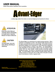
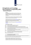
USER MANUAL Please review before installation and/or operation. ATTENTION Read this entire Manual carefully before attempting to install and/or operate. Retain for future reference. CAUTION To avoid injury, use care when lifting, installing, adjusting or operating. Patents Pending ©2011 Advant-Edge Paving Equipment, LLC At Advant-Edge Paving Equipment, we are constantly striving to develop products that make our highways safer and last longer. The Ramp Champ is designed to meet both of these objectives. This device has detachable and inter-changeable “shoes” so that the same basic unit can create either a 30º tapered safety edge along the side of the road or a longitudinal center lane joint often referred to as a Michigan Notch Joint to help make a better seam between two lanes. The Ramp Champ has been specifically designed and constructed to meet government guidelines that are being enacted to improve road safety. And, our patent pending reversible design allows the paving contractor to mount the unit on either side of the paver thereby avoiding the need to purchase a left and right side model. Advant-Edge Paving Equipment, LLC 33 Old Niskayuna Road Loudonville, New York 12211 Phone: 814.422.3343 (EDGE) [email protected] Website: www.advantedgepaving.com Ramp Champ User Manual 1 TABLE OF CONTENTS Section 1 Important Safety Precautions……………………………....page 3 Section 2 Product Overview……………………………………………..…..page 4 Section 3 Description of Key Parts……………………………………....page 7 Section 4 Initial Installation……………..…………………….…………..page 10 Section 5 Creating a Safety Edge.…………………………….…………page 12 Section 6 Creating a Center Lane Joint………………………..………page 15 Section 7 Reversing the Ramp Champ…………………………….….page 18 Section 8 Important User Information………………………………….page 20 Section 9 Trouble Shooting………………………………………………….page 21 Section 10 Maintenance…………………………………………………........page 22 Section 11 Warranty………………………………………………………….….page 23 Ramp Champ User Manual 2 1 IMPORTANT SAFETY PRECAUTIONS Please read the entire operating manual before installation or operation of this unit. Use only according to directions in this user manual or other officially published documents of Advant-Edge Paving Equipment, LLC. This unit is designed to be mounted on the screed or screed extension of paving machines and is intended for asphalt only. The Ramp Champ is HEAVY! To avoid injury, use care when lifting, installing or removing. It is recommended that appropriate work gloves be worn when installing, handling and using the Ramp Champ. Do not attempt to take apart, repair, modify or otherwise disassemble the Ramp Champ as it will void the warranty and can cause harm to the operator and others if not done correctly. If you are experiencing a problem, call Technical Support at 814422-3343 (EDGE). Always be sure that appropriately trained and qualified personnel are employed to install and operate the product. Also be sure that appropriate tools and procedures are followed at all times. During periods when the Ramp Champ is not in use, it is recommended that the holes in the screed (which were created for mounting) be filled (say with a spare bolt or screw) so as to keep them clean. WARNING! DO NOT DRAW THE SCREED EXTENSION TOO CLOSE TO THE MAIN SCREED. During paving, the Ramp Champ could be exposed to contact with the cross feed auger and auger shaft if the screed extension is drawn in too close to the main screed. Severe damage could occur to both the cross feed auger and the Ramp Champ if they come in contact. WARNING! RAISE THE FORMING BOX TO ITS UPPER MOST POSITION WHEN NOT PAVING AND/OR WHEN MOVING THE PAVER BETWEEN LOCATIONS. When paving is completed in a given direction and the paver is to be moved to a new location before paving again, the Ramp Champ should be raised to its uppermost position so that its forming edge is at a height above that of the screed. WARNING! IT MAY BE NECESSARY TO UNBOLT THE RAMP CHAMP PRIOR TO TRANSPORTING PAVER. When transporting the paving machine requires the screed extension to be retracted, it may be necessary on some paving machines to unbolt the Ramp Champ from the screed for transportation. Failure to do so will result in damage to the Ramp Champ and the paving machine. Ramp Champ User Manual 3 2. PRODUCT OVERVIEW Technical innovation has led to our new, next generation product: the Ramp Champ. It is capable of producing a variety of road edge profiles that meet the requirements of two different paving challenges: Paving road with safety edge 1. The tapered 30º safety edge is designed to make our highways safer by reducing the number of "run-off" accidents. 2. The longitudinal center lane joint enables paving crews to create an edge somewhat akin to the "Michigan Notch Wedge Joint" to be used when paving the first of two adjacent highway lanes. This edge will enable the second lane to "bind" with the first lane thereby creating a stronger and longer lasting seam. Right side oriented Ramp Champ Left side oriented Ramp Champ Ramp Champ User Manual 4 The Ramp Champ is reversible there is no need to purchase a left side and right side model as is the case with our competitors. With Advant-Edge Paving Equipment, it is buy one and it will perform on both sides of the paving machine. Our units are designed to automatically follow the shoulder elevation. When paving begins, the unit is set to the correct (or lowest) level shoulder height. As the paver moves forward, the Ramp Champ shoe will rotate up (or flatten out the slope of the edge) when it encounters higher shoulder levels (say for driveways). When the shoulder level returns to its normal level, the shoe will automatically rotate back to its original slope and height setting. As of today, the state and federal specifications being written for safety edges are aimed at creating a 30º slope. In some cases it may be advantageous to create a slightly flatter slope that takes into account a rolling pattern that later tends to increase the slope angle by several degrees. To a large extent creating an edge of 30º after rolling is as much art as science, but the Ramp Champ provides the operator with the flexibility to control the final slope angle. The slope setting of this unit may be changed in the field and set in a range from 5º to 30º. The Ramp Champ is fitted with shoes that create the desired edge profile. The shoes are detachable by the operator so a Ramp Champ being used as a safety edge maker can be transformed quickly into a longitudinal center lane joint maker. The safety edge shoe, has two forming surfaces. The leading surface is at an angle to the direction of travel and "funnels" the asphalt to aid compaction. The trailing surface is in line with the direction of travel. It acts as a trowel to smooth the surface and also as the surface which transmits the radial force thereby increasing compaction of the edge. The Safety Edge Shoe is designed to create an edge up to a maximum vertical drop of approximately 5". Safety Edge Profile Conventional Michigan Joint Profile Ramp Champ Center Lane Joint Profile The longitudinal center lane joint shoe is slightly more complex. It creates a profile similar to what is commonly referred to as a "Michigan Notch Wedge Joint." It has an upper Ramp Champ User Manual 5 vertical face where the edge meets the pavement mat surface, a tapered face (with an added groove in it to enhance seam binding), and a lower vertical face to provide sufficient material for structural integrity near the road bed. This shoe performs in a similar manner to the safety edge shoe in that they each utilize both compaction surfaces and trowel/radial force surfaces to enhance compaction. The Center Lane Joint Shoe is designed to accommodate pavement surface heights above the adjacent unpaved lane of 1" to 5". A note, although the Ramp Champ is reversible, the Center Lane Joint Shoe is not. The operator must purchase a left and right shoe to create center lane joints on either side of the paving machine. Achieving Desired Results of a 30º Tapered Safety Edge The Ramp Champ has been professionally designed and constructed to create a tapered safety edge slope of 5º to 30º (+/-1º) at the road shoulder. The slope can be adjusted in the field and set as desired by the operator. Please note that this slope angle is measured relative to the pavement mat which is normally different from true horizontal. Our company recognizes that no two road paving field conditions are identical and that various factors can create results that differ from the desired 30º target. Thus the value of being able to adjust the slope angle can be of great value in achieving the desired target. ACHIEVING THE TARGETED 30º ANGLE MAY BE DEPENDENT UPON A NUMBER OF FACTORS. THE FOLLOWING IMPORTANT OPERATING RULES WILL HELP TO ENSURE THE OPTIMAL ANGLE IS ACHIEVED: Unit is properly mounted and adjusted to the appropriate height (See Sections 4 “Installation” and 5 “Operation”). The temperature of the mix and the length of time before the first pass of the roller takes place can alter the slope angle. Softer, hotter mixes will tend to “push the asphalt out” and thereby create a steeper tapered angle. In this event the operator may wish to set the initial formation slope to say 25º as an example so that after rolling the slope will be the targeted 30º. Please remember that the 30º edge angle is relative to the slope of the pavement mat and not true horizontal. Ramp Champ User Manual 6 3. DESCRIPTION OF KEY PARTS Carefully unpack the shipping container and inspect the contents. You should find a fully assembled Ramp Champ with the Shoe that you ordered. Also in the shipping container is a full set of mounting hardware consisting of: two (2) ½-13 bolts, two (2) lock washers, four (4) regular washers and two (2) ½ -13 nuts. The Ramp Champ consists of six major components: the Mounting Plate, the Box, the Wedge, the Radial Force Cylinder, a Shoe and a Flap. Our product is built to be used by the road paving construction industry. Nearly all surfaces are made of ¼” steel remaining components such as the springs are made of the stainless steel and/or casted construction grade steel. Our threaded rod is ACME so that it can withstand the stress under paving operations and will withstand dirt and asphalt materials in which it may contact. Height Adjusting Screw Cotter Pin Radial Force Cylinder Cover Plate Box Wedge Shoe The Mounting Plate remains fixed and bolted to the screed thereby providing a foundation for the Ramp Champ to perform its functions. Mounting Slots are used when attaching the Mounting Plate to the screed extension of the paver. ½” bolts, washers, lock washers and nuts are provided to mount the unit. Guide Rails on the Mounting Plate prevent the Box from moving (or swinging) out of position. It is intended to make sure the Box maintains a vertical orientation and thus capable of creating consistent slope angles. The lower part of the Guide Rails are notched out so that the Center Lane Joint Shoe (when used) does not bind on the device. Note: this Mounting Plate has been designed to attach easily to most conventional screeds by simply drilling or tapping two holes in the screed or screed extension. The Box slides up and down vertically between the guide rails of the Mounting Plate. Its height relative to the Mounting Plate or screed is controlled by turning the Height Adjustment Screw. There is a Cotter Pin on the Height Adjustment Screw. Removal of the Cotter Pin is necessary to detach the Box from the Mounting Plate. The Cover Plate on the Ramp Champ User Manual 7 top of the Box protects the inner adjustment elements of the Box from dirt and asphalt. Inside the Box, just under the Cover Plate is a Slope Set Screw which can be used to set the maximum slope angle that the safety edge will create. The Wedge which is located on the bottom of the Box is designed to rotate (or flatten out) so that 1) different slope angles can be formed and 2) it can follow changes in the elevation of the adjacent road shoulder. On the bottom face of the Wedge are four tapped holes which are used to attach the Shoes. The Radial Force Cylinder produces downward and inward force (radial) on the Shoe which is one of our products unique features. The orientation of this force creates a more compact and stronger edge/joint. The amount of radial force applied to the Shoe can be controlled by turning the Spring Compression Screw. Safety Edge Shoe Longitudinal Center Lane Joint Shoe The Shoe, depending upon the profile chosen, produces either a tapered safety edge along the side of the road or a longitudinal center lane joint. The Shoe is attached to the bottom of the Wedge with screws and lock washers. Ramp Champ User Manual 8 The Flap limits the amount of excess asphalt that may “seep” between the end gate and the Wedge. It is attached to the Box and can slide up and down along an axis defined by the Flap Pins. It is held in place during operation by the Flap Spring. Please Note: The Flap is not required to create a strong quality edge. It only limits the amount of excess asphalt left near the finished edge or joint on the shoulder. The Flap will be most useful when creating safety edges of 20º to 30º. When creating center lane joints (with a vertical drop of 3” or less) or when creating relatively flat safety edge slopes, the amount of excess asphalt seepage will be small either with or without the Flap. The Flap contains a Flap Bar which makes contact with “push rods” that extend from the Shoe as shown above. These elements of design were included to prevent the Flap from binding when the Shoe pivots up and down. The Flap also has a series of notches or grooves on its side. These are used to provide the operator with an estimate of the safety edge slope angle being created during the paving operation. Each notch represents a 5 degree change in the tapered slope being created. Flap Flap Spring Box Flap Pins Ramp Champ User Manual 9 4. INITIAL INSTALLATION The Ramp Champ is normally shipped with only one end of the Flap Spring attached. As a first step upon unpacking the unit we suggest that you attach the other end. Many times this is easily done by stretching the spring slightly and looping it through the clevis pins at both ends as shown in the picture in the previous section. If this method proves to be difficult, we suggest that you unscrew the Flap Pins, then attach the Flap Spring. Then move the Flap into position and reattach the Flap Pins. Two holes must be made in the screed extension to mount the Ramp Champ to the Paver. Once these holes are made, the Ramp Champ unit will be easily attachable and detachable from the paving machine as needed. In most cases, the tools required are: a drill, a center tap, a small (metal) tap drill bit, ½” (metal) drill bit, and two (2) ¾” wrenches, one of which should preferably be a socket wrench. In some cases, where it is difficult to access the rear side of the screed, users may find it advantageous to tap holes in the screed extension or weld nuts to the back face of the screed extension that will serve as a secure threaded hole. This method will be explained as well. Step 1. Detach Mounting Plate from Box. Carefully remove the Ramp Champ from the shipping crate and place the assemble unit on the ground or a workbench. Do so carefully as the unit weighs approximately 115lbs. Remove the Cotter Pin at the top of the Height Adjusting Screw and slide the Box off the Mounting Plate. Step 2. Position Paver and Screed. Bring the paving machine to a location where the ground is relatively flat. Note: it need not be true horizontal so long as it is flat. Lower the screed to ground level. Place a 1” shim on the ground in front of the vertical face of the screed extension. With regard to the shim, the important factors are 1) that the bottom edge of the Mounting Plate remains parallel to the edge of the screed trowel surface and 2) the bottom edge of the Mounting Plate is approximately level with the top of the screed compaction edge which tapers up about an inch or so from the trowel level on most screeds. Step 3. Position Mounting Plate. Place the Mounting Plate on the 1” shim with the Mounting Slots at the top of the Mounting Plate. Next, slide the Mounting Plate horizontally along the shim until the outside edge of the Guide Rail is flush against the end gate. Important Note: The Ramp Champ has been designed to easily attach to most paving machines. But, if you find that the entire Mounting Plate surface is not flush against the screed face or if you find that the Mounting Plate is not plumb level or if you find that there is a lower prestrike-off plate that will interfere with the operation of the Ramp Champ when mounted, please STOP the installation process and contact us. Chances are you will need a Universal Mounting Bracket in order to attach the Ramp Champ to your paver. Step 4. Mark Holes. There are two horizontal Mounting Slots on the Mounting Plate. They are symmetrical in size and location. With the unit in position, carefully mark the center line of the two horizontal Mounting Slots then locate your two desired holes on this line and mark with a marker that is easy to see. Each hole will align with the center line of their Ramp Champ User Manual 10 respective slot. We have provided slots as opposed to holes so that you may orient the hole you are drilling slightly left or right should there be “obstacles” on the back side of the Screed extension you wish to avoid. It is best staying away from any obstacles as you may be needing to apply a wrench to a nut at the site whenever attaching or removing the Ramp Champ form the paving machine. Mounting Slot Mounting Slot Step 5. Drilling Holes. It is important that the holes be drilled are very close to where they were marked. Failure to drill in the proper location will result in the Ramp Champ not being perpendicular to the screed forming surface which means that it may not be possible to achieve desired safety edge slope angles. In many cases the paving machine provides the operator easy access to the back side of the vertical screed extension face behind the Mounting Plate. In these cases we suggest simply drilling two holes as described in Step 5(a) below. In cases where the access is limited or difficult, we suggest following the procedure outlined in Step 5 (b). Step 5 (a). Easy Access to Back of Screed Extension. Remove Mounting Plate from shim and set on the side. With a center punch or center tap, mark the center of the two holes to be drilled. Starting with a small pilot drill bit, drill a hole at each location. Next, drill two ½” holes – one for each of the two slots. Step 5 (b). Difficult Access to Back of Screed Extension. Remove Mounting Plate from shim and set on the side. Remove and detach the vertical screed extension face from the paving machine and confirm that there are no “obstacles” immediately behind the marked holes where a nut will be welded on. If there is, move the mark either left or right along the line that will keep it centered in the horizontal Mounting Slots. With a center punch or center tap, mark the center of the two holes to be drilled. Starting with a small pilot drill bit, drill a hole at each location. Next, drill two ½” holes – one for each of the two slots. Two nuts now need to be welded onto the back side of the screed extension. Be sure that each nut is aligned to the hole so that a ½” bolt passing through the hole will be able to Ramp Champ User Manual 11 thread into the nut. Reattach the vertical face of the screed extension to the paving machine. Please use only experienced personnel to install these features. Note: Some operators may wish tap holes directly in the vertical face instead of welding on two nuts. If you choose this method of tapping holes, please first make sure that the vertical face of the screed is sufficiently thick to accept such a tap for a ½” bolt. Step 6. Attaching Ramp Champ to Paving Machine. On the ground or a work bench reattach the Box to the Mounting Plate by sliding the Height Adjusting Screw through the yoke and reinserting the Cotter Pin. Position the unit at the screed extension next to the end gate and insert a ½” bolt and washer into each of the Mounting Slots and through the recently drilled ½” holes. (You may wish to place the unit back on to the 1” shim during the process to make it easier, but it is not necessary). Next slide on a washer and lock washer over the protruding bolt, screw on nut and tighten using appropriate wrenches. The Mounting Plate should be square to the screed and against the end gate. In case where a nut was welded on to the back of the screed extension we recommend sliding a lock washer and regular washer onto the bolt prior to sliding it through the Mounting Slot. 5. CREATING A SAFETY EDGE WITH THE RAMP CHAMP Setting up the Ramp Champ for Operation. The Ramp Champ is normally shipped with the Safety Edge Shoe attached to the Wedge and oriented for paving on the right side of the paving machine. This will create a safety edge on the road shoulder when paving in the direction of traffic. If the shoe is not attached, do so by holding the shoe in a vertical position and slipping all four flat head screws through the tapered holes in the shoe. Next, slip a lock washer on each of the protruding screws and then carefully move the shoe into position and thread screws into holes in the Wedge and tighten with an Allen wrench. If you are interested creating a safety edge with the Ramp Champ on the other side of the paving machine, see section 7 Reversing the Ramp Champ. If you intend to put down more than one lift or layer of asphalt, we suggest that you use the Ramp Champ only when applying the final lift. Once the paving machine is at the site and ready to begin paving, attach the Ramp Champ to the screed extension as described in Step 6 of Section 4 above. For a 30º slope angle (which is the factory setting of the Maximum Slope Set Screw, proceed as follows: Step 1. Turn the Spring Compression Screw clockwise until the spring begins to exert a force on the Wedge. You will notice that it becomes more difficult to turn the Spring Compression Screw when pressure is being applied. Continue turning the screw so that it travels down approximately ½” to 1”. Step 2. With the screed set at the anticipated paving level and the paver ready to begin paving, lower the Shoe until its bottom edge makes contact with the shoulder. This is done Ramp Champ User Manual 12 by turning the Height Adjustment Screw counter clockwise. The entire Box, Wedge and Shoe will move vertically down. Corrective Actions. The Ramp Champ is now set to create a tapered 30º safety edge as measured relative to the pavement surface. Should you find that the edge is less than a 30º slope it is most likely that the shoe needs greater radial compression force to apply against the asphalt or the shoulder elevation has risen relative to the initial height setting. These are easily fixed. If you believe the shoulder elevation has changed, simply turn the Height adjustment screw clockwise. This will raise the shoe vertically up and the radial force will return the shoe’s safety edge slope to 30º. If you believe it is not an elevation issue try increasing the radial force by turning the Spring Compression Screw clockwise an additional ½” or so. In some instances you may find that the slope is 30º but there is a “fall-off” at the outer most edge of the safety edge and that the compression of asphalt material does not appear very good at this edge. In this case, the shoe is probably set too high relative to the shoulder and needs to be lowered slightly by turning the Height Adjustment Screw counter clockwise. At first these adjustments may seem a little tricky but in very short order you should find a setting that is producing a good edge and need very little attention as the paver is laying down asphalt. Ramp Champ set at 30 Ramp Champ set at 15 Creating Safety Edge Slopes less than 30º. In some cases, say for example because of rolling patterns that tend to push out the asphalt thereby increasing the slope angle that was initially created by the shoe, the operator my wish to create a slightly flatter angle so that the final result will tie in with a 30º slope. Ramp Champ User Manual 13 One way to do this is to take off the Cover Plate and turn the Slope Set Screw clockwise until the desired maximum slope angle is reached. You will see that the wedge and/or shoe will not rotate down as far as the screw is tightened. For safety reasons, this action should never be done while the paving machine is being operated. The operator may wish to adjust the Slope Set Screw before the Ramp Champ is mounted on the paving machine because of the limited space involved. Once the maximum slope angle is set, follow steps 1 and 2 above. Cover Plate Slope Set Screw A second way to adjust the slope angle can be easily accomplished in the field while paving. First release the radial pressure on the shoe by turning the Spring Compression Screw counter clockwise. Second, turn the height adjustment screw counter clockwise moving the Box down. This will force the shoe into the shoulder and flatten out the angle. Third, increase the radial pressure on the shoe by turning the Spring Compression Screw clockwise. This final step of increasing pressure will keep the shoe from forming an even flatter slope and help to create a compacted safety edge. Should you experience problems of “holding” the desired angle you want, it may be because the shoulder is not firm enough to support the pressure. In that case you may need to follow the directions of adjusting the Slope Set Screw above. Ramp Champ User Manual 14 Measuring the results. We have calibrated the Flap with a series of notches that will provide a good estimate of the safety edge slope being created without having to constantly take measurements. When the top most edge is even with or just above the top of the Box, the angle is 30º. The second notch is set to correspond with 25º. Each additional notch represents a 5º differential. 6. CREATING A CENTER LANE JOINT WITH THE RAMP CHAMP Setting up the Ramp Champ for Operation. If you purchased the Ramp Champ for use with a Center Lane Joint Shoe, it was most likely shipped from the factory with the Shoe attached to the Wedge and oriented for paving on the left side of the paving machine. This will create a joint on the left edge of the road when paving in the direction of traffic. If the shoe is not attached, you must first make sure the Ramp Champ is oriented to be attached to the desired side of the paving machine. The pictures below show a left side and a right side orientation. If your unit is oriented correctly, continue on with this section. If not, go to section 7 Reversing the Ramp Champ. Reverse the orientation and then continue on in this section. Right side oriented Left side oriented Ramp Champ User Manual 15 Next, attach the Center Lane Joint Shoe by holding the shoe in a vertical position and slipping all four flat head screws through the tapered holes in the shoe. Then slip a lock washer on each of the protruding screws and carefully move the shoe into position and thread screws into holes in the Wedge and tighten with an Allen wrench. For a joint on the left hand side of the paving machine, the assembled Ramp Champ with Center Lane Joint Shoe is pictured below. Note that the Center Lane Joint Shoe is not reversible! If you desire to make a center lane joint on the right side of the paving machine you will need to purchase a “right side Center Lane Joint Shoe.” The remainder of the Ramp Champ is fully reversible. If you intend to put down more than one lift or layer of asphalt in a timely succession, we suggest that you use the Ramp Champ only when applying the final lift. Once the paving machine is at the site and ready to begin paving, attach the Ramp Champ to the screed extension as described in Step 6 of Section 4 above. Then proceed as follows: Step 1. Turn the Spring Compression Screw counter clockwise raising it until it stops (this is about 6” above the nut it threads in to). Step 2. With the screed set at the anticipated paving level and the paver ready to begin paving, lower the Shoe until its bottom edge makes contact with the adjacent (to be paved later) lane. This is done by turning the Height Adjustment Screw counter clockwise. The entire Box, Wedge and Shoe will move vertically down. Step 3. Continue turning the Height Adjustment Screw counter clockwise this will continue to move the Box down and in the process it will cause the shoe to rotate up or flatten out as it is “pushed” against the adjacent lane surface. Stop turning the Height Adjustment Screw when the Upper Vertical Notch is approximately ½” below the anticipated level of the new pavement surface. Ramp Champ User Manual 16 Step 4. Next, radial pressure is applied to the shoe so that it will not “float” or rotate up as paving begins. This is done by turning the Spring Compression Screw clockwise until it begins to exert a force on the Wedge. You will notice that it becomes more difficult to turn the Spring Compression Screw at this time. Continue turning the screw so that it travels down an additional ½” to 1”. Step 5. Begin paving. If the joint profile does not look exactly like you want, follow the corrective actions below. Corrective Actions. The Ramp Champ is now set to create a center lane joint that should safely let traffic traverse from the old to new pavement within approximately one to two hours (once the pavement has set). It should also be creating a joint profile as pictured above. Should you find that the Upper Vertical Notch is too deep or too shallow, adjust the joint profile by moving the Box up or down accordingly. This is done by first relieving the pressure on the Shoe by turning the Spring Compression Screw counter clockwise, second, turn the Height Adjustment Screw to raise or lower the unit and third, return the radial pressure to the shoe by turning the Spring Compression Screw clockwise as described in Step 4 above. Our Center Lane Joint Shoe profile is designed to create a Lower Vertical Notch that is ½” in depth. Should you find that you are creating a joint profile that has a Lower Vertical Notch greater than ½” you may wish to apply more radial pressure by turning the Spring Compression Screw clockwise. This action will also increase the asphalt compression and strength of the joint. At first these adjustments may seem a little tricky but in very short order you should find a setting that is producing a good joint and needs very little attention as the paver is laying down asphalt. Ramp Champ User Manual 17 7. REVERSING THE RAMP CHAMP At times it will be advantageous to create either the tapered safety edge or the center lane on the opposite side of the paving machine. For safety edges this may occur when the operator is paving in the direction against traffic or when the safety edge is being created on the shoulder of the median of the road. In either case the Ramp Champ is reversible and can be used on either side of the paving machine. In order to switch sides proceed as follows: Step 1. If the unit is currently attached to the paver, raise the Box until it is above the level of the screed trowel surface and unbolt it from the screed. Carefully move it to a safe place. Step 2. Remove the shoe from the Wedge being careful not to lose the lock washers. Step 3. Remove the Flap from the Box by disconnecting the Flap Spring and unscrewing the Flap Pins. Step 4. Remove the Cotter Pin on the Height Adjusting Screw and slide the Box off the Mounting Plate. Step 5. Rotate the Box 180º (i.e. flip it over) and slide it back onto the Mounting Plate and attach the cotter pin. Step 6. Attach the Safety Shoe by rotating it 180º. The shoe is attached by holding it in a vertical position and slipping all four flat head screws through the tapered holes in the shoe. Next, slip a lock washer on each of the protruding screws and then carefully move the shoe into position and thread screws into holes in the Wedge and tighten with an Allen wrench. Note: the same safety Shoe can be used on either side of the paving machine by simply rotating it 180º. This is not the case with the Center Lane Joint Shoe. These shoes have a left and right orientation and the appropriate shoe must be purchased and used on each side. Step 7. Reversing the Flap by first reversing the position of the Flap Bar. This is done by unscrewing the two screws that hold the Flap Bar in place, flipping the Flap over, and then re-attaching the Flap Bar on the opposite side of the Flap. Step 8. Attach the Flap by securing it in place using the two Flap Pins that had been removed. You will see that there are two holes for the Flap Pins facing up (away from the Mounting Plate) on the side of the Box that will now be closest to the end gate. Next, attach the Flap Spring. If this proves to be difficult, we suggest that you unscrew the Flap Pins, then attach the Flap Spring. Then move the Flap into position and reattach the Flap Pins. Ramp Champ User Manual 18 Step 9. The Ramp Champ is now ready to attach to the other side of the paving machine. If mounting holes are already in place, simply bolt on. If not, follow the mounting and installation instructions in section 3. Flap Bar Push Rod Ramp Champ User Manual 19 8. IMPORTANT USER INFORMATION Lane Width. The width of the tapered safety edge is not to be included in the total measurement of the desired lane width. The end gate needs to be extended beyond the desired lane width by an amount equal to the width of the tapered edge. Fully extended the Ramp Champ creates a 30º tapered edge that is approximately 8” wide. Rolling Patterns. It is recommended that the first rolling pass on the freshly laid road be made with the roller drum 8” to 12” away from the tapered edge of the lane. This will help to ensure that the tapered edge will not “roll up” or push out due to outward pressure from the roller. The roller should be driven straight up to the back of the paver and reversed without turning the roller so as to keep constant distance from the edge. Rolling the edge. Attempting to roll the tapered edge is likely result in damage or distortion of the edge. It is not necessary to roll the edge as the Ramp Champ’s patent pending radial compaction pressure creates a very strong and viable edge. WARNING! DO NOT DRAW THE SCREED EXTENSION TOO CLOSE TO THE MAIN SCREED. During paving, the Ramp Champ could be exposed to contact with the cross feed auger and auger shaft in some models of paving machines when the screed extension is drawn in too close to the main screed. Please check if this is the case with your machine. Severe damage can occur to both the cross feed auger and the Ramp Champ if they come in contact. WARNING! RAISE THE BOX TO ITS UPPER MOST POSITION BEFORE MOVING OR TRANSPORTING THE PAVER. When paving is completed in a given direction and the paver is to be moved to a new position, the Ramp Champ should be raised to its uppermost position. Keeping the End Gate in Proper Position. In order for the Ramp Champ to work properly, the end gate should be riding directly on the surface of the shoulder being paved at all times. Most end gates have a tension rod or compression spring mechanism which can be adjusted to keep enough downward pressure on the end gate so that it does not lift up during paving. If the end gate lifts off the shoulder for any reason, asphalt may flow out the side of the paver and not provide enough asphalt to the Ramp Champ to achieve proper consolidation. Ramp Champ User Manual 20 9. TROUBLE SHOOTING No visible angle has been produced or the angle doesn’t reach the road shoulder Check if the Shoe has been lowered to the appropriate position (See Section 5. CREATING A SAFETY EDGE WITH THE RAMP CHAMP) If not, turn the Height Adjusting Screw counterclockwise until the Shoe reaches the shoulder of the road while the screed is resting on the new pavement. The angle of the paved surface is tearing This may be due to the temperature of the mix; mixes that are too cool may cause the material to tear. The composition of the mix may be at fault as well; mixes that are too dry may cause tears in the surface. The angle appears to be too steep The Ramp Champ is designed to create at most a 30º slope. First make sure the angle is being measured relative to the road’s surface, not true horizontal. Be sure that the correct rolling patterns have been used (See Section 5.2, “Rolling Patterns”). Check the unit and make sure it is flush against the end gate and square to the screed forming surface. Check the Box and be sure it is nestled between the Guide Rails. The tapered safety edge seems to lack structural integrity and is breaking up The underlying shoulder and ground beneath the safety edge being formed must be firm and compacted prior to paving. Failing to do this may result in an inability to form a quality edge either during the paving process, and/or after the road is completed as the surrounding shoulder “settles.” The devise is cutting through the shoulder instead of moving with the terrain If the shoulder is not too soft, this may occur when the Spring Compression Screw is too tight and creating too much radial force or when the Shoe is too low and the Height Adjustment Screw need to be turned clockwise to raise the Shoe. The Height Adjusting Screw will no longer turn counterclockwise Our unit is designed with both upper and lower limit stops. In its highest position, the Shoe will be even with or just above the lower edge of the Mounting Plate. The lower stop allows the top edge of the Shoe to reach a position approximately 2″ lower than the bottom edge of the Mounting Plate. The unit is designed in this way in order to maintain is operating performance. The Screws are stuck or seems too difficult to turn First clean off all threads using your normal asphalt cleaning process. If the difficulty still exists, the screw may have been damaged or bent and may need to be replaced. We believe this is not likely to happen although, should it occur we will be able to supply you with replacement parts. Replacing the Height Adjusting Screw is not difficult. The Spring Compression Screw will need to be repaired at the factory. Ramp Champ User Manual 21 Asphalt is accumulating on the shoulder next to the edge or joint being created. This can be due to the end gate not being sufficiently low enough or the Flap not being adjusted correctly. First check the end gate settings. If this is okay, the Flap may need to be lowered. This can be done by grinding down or cutting off a portion of the “push rod” that extends from the Shoe and makes contact with the Flap Bar. For assistance during preparation, installation and use of the Ramp Champ call Technical Support at 1-814-422-3343 (EDGE) or e-mail us at [email protected] 10. MAINTENANCE We suggest that you care for your Ramp Champ in a manner similar to all other paving machine accessories. The unit should be cleaned daily after use with your usual asphalt cleaning solutions. We recommend those that are environmentally safe. Additionally, the Ramp Champ should be stored in a dry location. Constant exposure to rain and weather conditions may affect its performance. Ramp Champ User Manual 22 11. WARRANTY EXPRESS LIMITED WARRANTY. Advant-Edge Paving Equipment, LLC warrants to the original purchaser only (Buyer) and subject to the limitations, terms and conditions and exclusions set forth herein: the Ramp Champ unit(s) are warranted only against failure due to defective material or workmanship for the period of one (1) year from the date of delivery. THIS WARRANTY IS IN LIEU OF ALL OTHER WARRANTIES, WHETHER EXPRESS, IMPLIED OR STATUTORY, AND ALL OTHER LIABILITIES (CONTRACT, TORT OR OTHERWISE, INCLUDING NEGLIGENCE) AND ADVANT-EDGE PAVING EQUIPMENT, LLC MAKES NO WARRANTY OF MERCHANTABILITY OR OF FITNESS FOR ANY PARTICULAR PURPOSE. THIS WARRANTY WILL AUTOMATICALLY TERMINATE AND BECOME VOID UPON THE SALE, TRANSFER OR CONVEYANCE OF THE RAMP CHAMP UNIT(S) OR MACHINE, MACHINE ATTACHMENT OR PROPERTY ON WHICH THE RAMP CHAMP UNIT(S) ARE INSTALLED AND OPERATED. ADVANT-EDGE PAVING EQUIPMENT, LLC DOES NOT MAKE ANY WARRANTY OR ASSUME ANY OBLIGATION WITH RESPECT TO THE VALIDITY OF ANY PATENTS, DESIGNS, COPYRIGHTS OR TRADEMARKS WHICH MAY COVER SUCH RAMP CHAMP UNIT. THE CONDITIONING OF LIABILITY, RIGHTS, OBLIGATIONS AND REMEDIES OF THE BUYER RELATING TO CLAIMS ARISING FROM A DEFECTIVE RAMP CHAMP UNIT(S) SHALL BE GOVERNED EXCLUSIVELY BY THE TERMS OF THIS SECTION 11 HEREOF. This EXPRESSED LIMITED WARRANTY does NOT apply where there has failure of the Ramp Champ unit(s) due to improper use; breakage not due to defect, including, but not limited to, natural forces and/or acts of God; failure on account of faulty or improper installation or handling; where repairs or modifications have been made or attempted by others; or failure on account of installation in or on a product of faulty design or construction. As an example, this EXPRESS LIMITED WARRANTY will NOT apply if an object of any kind is attached to Ramp Champ unit without the prior written consent of Advant-Edge Paving Equipment, LLC. Sales representatives of Advant-Edge Paving Equipment, LLC are not authorized to make warranties about the Ramp Champ unit. Advant-Edge Paving Equipment, LLC sales representatives' ORAL STATEMENTS DO NOT CONSTITUTE WARRANTIES, shall not be relied upon by Buyer, and are not part of the contract for sale. If Buyer believes it has purchased a defective Ramp Champ unit(s) as described above, Buyer must notify Advant-Edge Paving Equipment, LLC immediately in writing why Buyer believes the Ramp Champ unit(s) are defective. Advant-Edge Paving Equipment, LLC may then request the Buyer to return the allegedly defective Ramp Champ unit(s) to AdvantEdge Paving Equipment, LLC; have an Advant-Edge Paving Equipment, LLC representative inspect the unit(s) at the job site, as installed, or at Advant-Edge Paving Equipment, LLC’s address; and/or rely upon the information Buyer has provided to determine whether the unit(s) are defective as described above. If any unit(s) are proven to be defective as Ramp Champ User Manual 23 described above, then Advant-Edge Paving Equipment, LLC will, at Advant-Edge Paving Equipment, LLC’s sole discretion, either repair or replace the defective unit(s) or issue to Buyer a credit equal to the price of the defective unit(s) charged by Advant-Edge Paving Equipment, LLC to Buyer. Said repair or replacement of defective unit(s) or issuance of credit shall constitute fulfillment of all liabilities of Advant-Edge Paving Equipment, LLC to Buyer with respect to, or arising out of, the unit(s), whether based on contract, negligence, strict tort or otherwise. Advant-Edge Paving Equipment, LLC reserves the right to change design, color, models and to discontinue the manufacture of any unit(s). LIMITATION OF LIABILITY. Advant-Edge Paving Equipment, LLC shall not under any circumstances be liable for incidental damages or for special or consequential damages. The remedies of Buyer set forth herein are exclusive, and the liability of Advant-Edge Paving Equipment, LLC with respect to any contract or anything done in connection therewith such as the performance or breach thereof, or from the manufacture, sale, delivery, resale, installation or use of any Ramp Champ unit(s) covered by or furnished to Buyer, whether arising out of contract, negligence, strict tort, or under any warranty or otherwise, shall not, except as expressly provided herein, exceed the price of the unit(s) upon which such liability is based. This limitation of liability applies to original and replacement unit(s). CONTROLLING LAW. The sale, delivery and use of Ramp Champ unit(s) shall be governed by, and this warranty shall be construed and enforced in accordance with, the laws of State of New York. ************************* Advant-Edge Paving Equipment, LLC 33 Old Niskayuna Road Loudonville, New York 12211 Phone: 814.422.3343 (EDGE) [email protected] Website: www.advantedgepaving.com ************************* Ramp Champ User Manual 24