1
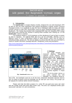
mpc64up © JDP’MMXIII
MIDI Gadgets Boutique Inc.
mpc64up
Universal MIDI keyboard encoder
* user’s guide *
1. What is this?
mpc64up is the user-programmable successor of one of our best-selling
units: mpc64xr and covers its entire functionality, adding better
performance, wider capabilities within smaller size and lower cost.
mpc64up is capable to scan and encode to MIDI up to 64 key contacts or
general contacts configured for passive or active keying. It has 7
additional switch/button inputs as well as 8 analog inputs where
potentiometers can be wired directly for
allowing Continuous control by
faders, pedals etc.
Hence, mpc64up has the capability of encoding up to 64 + 7=71 contacts
and 8 potentiometers. This is enough for most typical keyboard or control
applications involving standard 5-octave keyboard and expression controls
(faders, pedals).
The most important capability of this unit though is its userprogrammability! Each of contacts can be programmed to send any combination
of up to 32 MIDI bytes upon engaging and up to 32 MIDI bytes upon releasing.
Each of potentiometers can be programmed to send up to 32 MIDI bytes upon
position change where one or more of these bytes can carry the data about
potentiometer's position (number between 0 and 127).
The
support
of
user-programmability
allows
using
mpc64up
for
controlling virtually any MIDI-controllable software.
Last but not least: mpc64up has MIDI Merge input capable of full
merging, with 256-byte buffer, allowing other software applications to be
cascaded to mpc64up without additional virtual merging software. The MIDI
input is also used for programming MIDI events in mpc64up.
2. How it works?
In mpc64up internal program memory there is a table of MIDI bytes. For
each of key inputs there are two entries/strings containing 32 MIDI-bytes:
one string for On event and the other string for Off event. For each of
potentiometers there is an 32-byte entry/string containing 32 MIDI bytes
that are sent upon each potentiometer position change.
Hence, there is a table of totally 64 + 7 + 8 = 79 MIDI strings, each
32 bytes long.
Each of these strings can be reprogrammed by user for any MIDI
content. The string can contain MIDI status bytes, MIDI Data bytes, System
and Realtime MIDI messages, etc. It is entirely up to the user what MIDI
string will be sent by triggering/changing each of mpc64up inputs.
The programming is done by uploading the specific MIDI string to
specific table entry via mpc64up MIDI input. An special Windows-based
application was designed for this purpose, called mpc64upprg.exe. It is
available for free download on our site (follow links on mpc64up product
page).
The mpc64up can be programmed using other Windows or non-Windows
applications, providing that they can send user-defined System Exclusive
messages and user-defined MIDI strings. The programming sequence and
messages protocol and format are described in Appendix A of this document.
3. MIDI implementation
Appendix B shows the factory-programmed MIDI implementation of
mpc64up.
This MIDI implementation can be used as it is and can be changed by
user when/if necessary. In it each of scan points triggers NoteOn/NoteOff
messages on separate channel per scan matrix. MIDI Channel 1 is covered. The
note range is MIDI notes 36 – 99. The additional switch/button inputs
trigger Control Change messages (CC80-CC86) on MIDI channel 1. The
[email protected]
www.midiboutique.com
mpc64up © JDP’MMX
MIDI Gadgets Boutique Inc.
2
continuous/potentiometer inputs trigger continuous controller CC7 (Volume)
on MIDI channels 1-8.
4. Wiring diagrams
Normally, the mpc64up is used in systems with passive (GND) keying. It
can be confuigured for active positive or active negative keying viltage
upon request. Unless other requested the unit is supposed to work with
passive keying. An unit configured for passive keying MUST NOT Be used
insystems with active keying. Applying keying voltage in such unit would
damage it! the keying voltage can be configured for Key inouus only!. The
additional switch/button inputs cannot be configured for anything than GMD
keying. The wiring diagram showing all cases of wiring can be foiund in
Appendix C.
The key/switch/button and potentiometer control inputs should
be connected to keys/switches/buttons and potentiometers as shown on
schematic. Each non-wired key/button/switch input will be read as being open
contact (break). Each potentiometer input left unconnected will be read as
potentiometer left in Max position. A key/button/switch input connected to
GND will be read as being closed contact (make). In case potentiometer input
is grounded it will be read as potentiometers left in Min position.
The proper Control Change (or other programmed by user) messages for
each button/switch and potentiometer
will be transmitted once upon on
initializing (starting up).
[email protected]
www.midiboutique.com
mpc64up © JDP’MMX
MIDI Gadgets Boutique Inc.
3
5.Technical specification.
Parameter
Value
Unit
Comment
Power supply voltage
Power supply current
9-12
V
50
mA
Any adapter/transformer capable to
source 50mA or more at 912V AC/DC can be used
Number of contact
inputs (scan
points)
64 + 7 = 71
-
Normally open or normally closed
type
Scan rate for contacts
300
S-1
Each key contact is being scanned
300 times per second
Number of
analog/potentiometer
inputs
8
Scan rate or
potentiometers
50
S-1
MIDI messages
User-defined
-
MIDI channels
User-defined
-
MIDI Merge
Yes
-
256 byte buffer
Size
13.4x8.4x2.5
cm
Approx. 5.3”x3.3”x1”
Weight
70
g
Approx. 2.5 oz
[email protected]
www.midiboutique.com
10 - 100 kOhm linear
potentiometers (preferably 10kOhm)
Each potentiometer is being
scanned 50 times per second
Up to 32-byte MIDI user-defined
string per event
Defined per MIDI event (single
MIDI string can contain MIDI
messages going on various MIDI
channels
mpc64up © JDP’MMX
MIDI Gadgets Boutique Inc.
4
Appendix A. mpc64up – Programming
Step-by-step programming sequence
1. Download the mpc64upprg.zip file from our site (www.midiboutique.com). The
actual link can be found on mpc64up product page.
2. Copy and unzip the downloaded file to dedicated folder.
3. Connect computer's MIDI output to mpc64up MIDI input using standard MIDI cable.
4. Power up the mpc64up.
5. Run the unzipped mpc64upprg.exe utility.
6. Select the proper MIDI output port from 'MIDI Output' drop-down list.
NOTES:
Some systems may have more than one MIDI output, there could be hardware and
virtual ports as well. Make sure you have selected the hardware port that is connected
to mpc64up in previous steps.
[email protected]
www.midiboutique.com
mpc64up © JDP’MMX
MIDI Gadgets Boutique Inc.
5
7. Select the event you want to program. All user programmable MIDI events are listed in
'mpc64up Input/EVENT' drop-down list. There are three groups of events: ON-event for
contact inputs, OFF-event for contact inputs and CHANGE events for potentiometer
inputs.
8. Choose desired event content byte-by-byte by selecting byte values.
NOTES:
Bytes that have assigned 'Empty' will be reset to value of FF.
For any event, each byte that has been assigned HEX value of FF will be ignored and
won't be producing MIDI output traffic.
For potentiometer events each byte that has been assigned HEX value of F6 will be
replaced by potentiometer data in range 0-127 as read from potentiometer.
Hence, System Reset MIDI message (HEX FF) cannot be programmed in any event
and Tune Request MIDI message (HEX F6) cannot be programmed in potentiometer
events.
[email protected]
www.midiboutique.com
mpc64up © JDP’MMX
MIDI Gadgets Boutique Inc.
6
9. After the MIDI string has been configured, press once the 'Send' button at the bottom.
10. Repeat steps 6 .. 9 as many times as necessary for programming desired events.
11. The unit is programmed and can be used.
NOTES:
The programmed MIDI strings will be permanently kept in non-volatile (powerindependent) memory and won't change until next programming.
More than one mpc64up unit can be chained together and will be programmed
simultaneousness as each mpc64up would retransmit whatever MIDI traffic it gets.
Programming protocol
The programming protocol includes three parts:
Header message.
This is optional 10-byte System exclusive message that only causes reset of program
input queue (the 32-byte input buffer that receives the MIDI string to be programmed).
During reset, all the 32 bytes of Program buffer are set to HEX value of FF. If the string
to be programmed is 32 bytes long, the header message can be omitted as the input
queue will be updated entirely . The format of this message is:
Header message
F0
00
21
7F
0D
00
xx
xx
xx
F7
–
–
-
- 10 bytes (all shown in HEX format)
SysEx start
first ID
sec. ID (MGB)
thd. ID (MGB)
Device ID (mpc64up)
Device sub-ID (message ID=0: Reset buffer)
future use byte (set to 00)
future use byte (set to 00)
future use byte (set to 00)
SysEx end
The MIDI string itself.
It can be between 0 and 32 bytes long. In case of 0 bytes, the MIDI string for the
programmed event is considered empty and this event won't be producing any MIDI
output. This has the same effect as programming HEX FF value to all 32 bytes of this
[email protected]
www.midiboutique.com
mpc64up © JDP’MMX
MIDI Gadgets Boutique Inc.
7
string. This feature is suitable for programming switches that would transmit Program
change messages upon contact make and nothing upon contact break.
If an MIDI string is longer than 32 bytes, only the last 32 bytes will take place. Any MIDI
bytes of any order can be transmitted. The only two values that have special meaning
are HEX FF (MIDI Reset) and HEX F6 (Tune Request). These are used for inserting
special parameters in MIDI string. Refer to notes after the Step 8 of step-by-step
programming sequence described above about these special considerations.
Footer message.
This is obligatory 10-byte System exclusive message that passes to mpc64up the table
entry number to be programmed, and invokes the memory-write routines to copy the
input buffer content to proper table entry.
Footer message
F0
00
21
7F
0D
01
ll
mm
xx
F7
–
-
- 10 bytes (all shown in HEX format)
SysEx start
first ID
sec. ID (MGB)
thd. ID
Device ID (mpc64up)
Device sub-ID (message ID = 01: Store buffer)
Entry number, LSB (7-bit value 00..7F)
Entry number, MSB (7-bit value 00..07)
Bytes in buffer (00..20)
SysEx end
[email protected]
www.midiboutique.com
mpc64up © JDP’MMX
MIDI Gadgets Boutique Inc.
Appendix B. mpc64up – factory MIDI implementation
Keys
Key#
Control type
MIDI message
on make
MIDI message
on break
MIDI channel Comment
1 momentary contact/switch
NoteOn #36
NoteOff #36
1
2 momentary contact/switch
NoteOn #37
NoteOff #37
1
3 momentary contact/switch
NoteOn #38
NoteOff #38
1
4 momentary contact/switch
NoteOn #39
NoteOff #39
1
5 momentary contact/switch
NoteOn #40
NoteOff #40
1
6 momentary contact/switch
NoteOn #41
NoteOff #41
1
7 momentary contact/switch
NoteOn #42
NoteOff #42
1
8 momentary contact/switch
NoteOn #43
NoteOff #43
1
9 momentary contact/switch
NoteOn #44
NoteOff #44
1
10 momentary contact/switch
NoteOn #45
NoteOff #45
1
11 momentary contact/switch
NoteOn #46
NoteOff #46
1
12 momentary contact/switch
NoteOn #47
NoteOff #47
1
13 momentary contact/switch
NoteOn #48
NoteOff #48
1
14 momentary contact/switch
NoteOn #49
NoteOff #49
1
15 momentary contact/switch
NoteOn #50
NoteOff #50
1
16 momentary contact/switch
NoteOn #51
NoteOff #51
1
17 momentary contact/switch
NoteOn #52
NoteOff #52
1
18 momentary contact/switch
NoteOn #53
NoteOff #53
1
19 momentary contact/switch
NoteOn #54
NoteOff #54
1
20 momentary contact/switch
NoteOn #55
NoteOff #55
1
21 momentary contact/switch
NoteOn #56
NoteOff #56
1
22 momentary contact/switch
NoteOn #57
NoteOff #57
1
23 momentary contact/switch
NoteOn #58
NoteOff #58
1
24 momentary contact/switch
NoteOn #59
NoteOff #59
1
25 momentary contact/switch
NoteOn #60
NoteOff #60
1
26 momentary contact/switch
NoteOn #61
NoteOff #61
1
27 momentary contact/switch
NoteOn #62
NoteOff #62
1
28 momentary contact/switch
NoteOn #63
NoteOff #63
1
29 momentary contact/switch
NoteOn #64
NoteOff #64
1
30 momentary contact/switch
NoteOn #65
NoteOff #65
1
31 momentary contact/switch
NoteOn #66
NoteOff #66
1
32 momentary contact/switch
NoteOn #67
NoteOff #67
1
33 momentary contact/switch
NoteOn #68
NoteOff #68
1
34 momentary contact/switch
NoteOn #69
NoteOff #69
1
35 momentary contact/switch
NoteOn #70
NoteOff #70
1
36 momentary contact/switch
NoteOn #71
NoteOff #71
1
37 momentary contact/switch
NoteOn #72
NoteOff #72
1
38 momentary contact/switch
NoteOn #73
NoteOff #73
1
39 momentary contact/switch
NoteOn #74
NoteOff #74
1
40 momentary contact/switch
NoteOn #75
NoteOff #75
1
41 momentary contact/switch
NoteOn #76
NoteOff #76
1
42 momentary contact/switch
NoteOn #77
NoteOff #77
1
43 momentary contact/switch
NoteOn #78
NoteOff #78
1
[email protected]
www.midiboutique.com
8
mpc64up © JDP’MMX
MIDI Gadgets Boutique Inc.
44 momentary contact/switch
NoteOn #79
NoteOff #79
1
45 momentary contact/switch
NoteOn #80
NoteOff #80
1
46 momentary contact/switch
NoteOn #81
NoteOff #81
1
47 momentary contact/switch
NoteOn #82
NoteOff #82
1
48 momentary contact/switch
NoteOn #83
NoteOff #83
1
49 momentary contact/switch
NoteOn #84
NoteOff #84
1
50 momentary contact/switch
NoteOn #85
NoteOff #85
1
51 momentary contact/switch
NoteOn #86
NoteOff #86
1
52 momentary contact/switch
NoteOn #87
NoteOff #87
1
53 momentary contact/switch
NoteOn #88
NoteOff #88
1
54 momentary contact/switch
NoteOn #89
NoteOff #89
1
55 momentary contact/switch
NoteOn #90
NoteOff #90
1
56 momentary contact/switch
NoteOn #91
NoteOff #91
1
57 momentary contact/switch
NoteOn #92
NoteOff #92
1
58 momentary contact/switch
NoteOn #93
NoteOff #93
1
59 momentary contact/switch
NoteOn #94
NoteOff #94
1
60 momentary contact/switch
NoteOn #95
NoteOff #95
1
61 momentary contact/switch
NoteOn #96
NoteOff #96
1
62 momentary contact/switch
NoteOn #97
NoteOff #97
1
63 momentary contact/switch
NoteOn #98
NoteOff #98
1
64 momentary contact/switch
NoteOn #99
NoteOff #99
1
MIDI message
on make
MIDI message
on break
MIDI channel Comment
1 momentary contact/switch
CC#80 On
CC#80 Off
1
2 momentary contact/switch
CC#81 On
CC#81 Off
1
3 momentary contact/switch
CC#82 On
CC#82 Off
1
4 momentary contact/switch
CC#83 On
CC#83 Off
1
5 momentary contact/switch
CC#84 On
CC#84 Off
1
6 momentary contact/switch
CC#85 On
CC#85 Off
1
7 momentary contact/switch
CC#86 On
CC#86 Off
2
Buttons
Button#
Control type
Potentiometers
Pot#
Control type
MIDI message on change
potentiometer or control
CC7 (Volume)
1 voltage 0 .. +5V
potentiometer or control
2 voltage 0 .. +5V
potentiometer or control
3 voltage 0 .. +5V
potentiometer or control
4 voltage 0 .. +5V
potentiometer or control
5 voltage 0 .. +5V
potentiometer or control
6 voltage 0 .. +5V
potentiometer or control
7 voltage 0 .. +5V
8 potentiometer or control
[email protected]
www.midiboutique.com
MIDI channel Comment
1
CC7 (Volume)
2
CC7 (Volume)
3
CC7 (Volume)
4
CC7 (Volume)
5
CC7 (Volume)
6
CC7 (Volume)
7
CC7 (Volume)
8
9
mpc64up © JDP’MMX
voltage 0 .. +5V
[email protected]
www.midiboutique.com
MIDI Gadgets Boutique Inc.
10
mpc64up © JDP’MMX
MIDI Gadgets Boutique Inc.
11
Appendix C. Wiring diagram
NOTE:
More detailed copy of this diagram is available on our site in .pdf format!
[email protected]
www.midiboutique.com