1
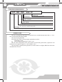
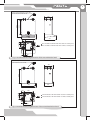
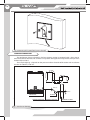
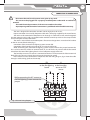
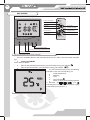
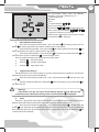
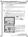
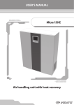
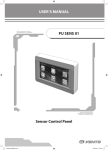
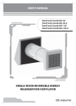
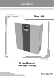
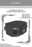
USER MANUAL
Air handling unit
with heat recovery
VUT 300 EVK mini EC
VUT 300 EV mini EC
VUT 301 EVK mini EC
VUT 301 EV mini EC
2
VUT 300 (301) EV(K) mini EC
CONTENTS
Introduction
Use
Delivery set
Structural designation key
Technical data
Safety requirements
Structure and operating logic
Mounting and set-up
Condensate drainage
Connection to power mains
Unit control
Maintenance
Fault handling
Storage and transportation rules
Manufacturer’s warranty
Acceptance certificate
Electrical connection certificate
Warranty card
3
3
3
4
4
6
7
8
10
11
12
19
22
23
23
24
24
24
3
INTRODUCTION
The present user manual consisting of technical details, operating instructions and technical
specification covers the installation of the VUT 300 (301) EV (K) mini EC air handling unit with heat
recovery, VENTS series (hereinafter the unit).
USE
The unit is designed to save thermal energy by means of heat recovery and is one of the energy
saving components used in buildings and premises.
The air handling unit is a component unit and is not designed for independent operation.
The unit is designed to provide permanent controllable air exchange by mechanical ventilation
in houses, offices, hotels, cafés, meeting halls and other mechanically ventilated premises as well as
utilization of extract air heat energy to warm up supply purified air.
Transported medium must not contain any flammable or explosive mixtures, evaporation of
chemicals, coarse dust, soot and oil particles, sticky substances, fibrous materials, pathogens or any
other harmful substances.
Warning!
The unit is not allowed for operation without properly installed fat filters or with
the clogged fat filters because ingress of oil and sticky substances may damage the
unit.
The unit is not designed to be used by children, physically or mentally disabled
persons, persons with sensory disorder or with no appropriate experience or expertise.
The unit must be handled only by properly qualified personnel after the
appropriate safety briefing.
Install the unit to be out of reach of children.
DELIVERY SET
Unit
User’s manual
Remote controller
Shipping box
Fastener kit
- 1 item;
- 1 item;
- 1 item;
- 1 item;
- 1 item.
4
VUT 300 (301) EV(K) mini EC
STRUCTURAL DESIGNATION KEY
VUT 300 EVK
mini EC
Modification
K - kitchen hood
Spigot orientation
V - vertical
Motor type
electronically commutated
Electric heater
Air capacity, m³/h
300 - unit with an integrated control panel;
301 - unit with a remote control panel.
Unit type
VUT - heat recovery ventilation
TECHNICAL DATA
The unit is designed for operation in an enclosed area at ambient temperatures from +1 ºC to +
40 ºC at relative humidity of up to 80%.
The unit must be grounded!
Hazardous parts access and water ingress protection standard:
Unit motors - IP 44;
Unit assembly connected to air ducts - IP 22.
The unit series designations, their main outside and connecting dimensions, appearance and
technical data are given in figures 1, 2 and in Tables 1 and 2.
The unit design is regularly being improved, so some models can slightly differ from those ones
described in this manual.
5
remote control panel fixed on 10 m cable
for the units VUT 301 EVK mini EC
Su. Mo. Tu. We. Th. Fr.
RT
SET
88
Sa.
88 : 88 h
TIMER ON
TIMER OFF
C
659
840
350
Su. Mo. Tu. We. Th. Fr.
RT
SET
88
Sa.
88 : 88 h
TIMER ON
TIMER OFF
C
627
132
521
85
380
160
The unit VUT 300 EVK mini EC with a built-in control panel;
The unit VUT 301 EVK mini EC with a remote control panel.
50
380
Fig. 1. Overall and connecting dimensions of the Unit with kitchen hood
remote control panel fixed on 10 m cable
for the units VUT 301 EV mini EC
Su. Mo. Tu. We. Th. Fr.
RT
SET
88
Sa.
88 : 88 h
TIMER ON
TIMER OFF
C
659
350
Su. Mo. Tu. We. Th. Fr.
RT
SET
88
Sa.
88 : 88 h
TIMER ON
TIMER OFF
C
595
627
380
85
132
370
160
The unit VUT 300 EV mini EC with a built-in control panel;
The unit VUT 301 EV mini EC with a remote control panel.
50
380
Fig. 2. Overall and connecting dimensions of the unit without kitchen hood
6
VUT 300 (301) EV(K) mini EC
Table. 1. Technical parameters of the unit
Model
VUT 300 (301) EV(K) mini EC
Unit voltage [V]
230 / 50 Hz
Max. fan power [W]
187
Fan current [A]
1,1
Electric heater power [kW]
1,5
Electric heater current [A]
6,5
Total unit power [kW]
1,69
Max. unit current [A]
7,6
Max. air capacity [m3/h]
270
Noise level, 3 m [dB(A)]
42
Max. transporting air temperature [°C]
from -25 °C up to +60 °C
Casing material
polymer coated steel
Insulation
15 mm ( foiled polypropylene foam)
Filter: extract/supply
G4 / G4
Connected duct diameter [mm]
Ø125
Weight [kg]
38/37
Heat recovery efficiency
up to 95%
Heat exchanger type
counter-flow
Heat exchanger material
polystyrene
* - only for the unit VUT 300 (301) EV mini EC
without kitchen hood
Table 2 . Control Panel Specifications
Ambient Temperature [0C]
from 0 to 40
Relative Humidity [%]
from 5 to 90 (without condensation)
Cable Section [mm2]
from 0.18 to 0.35
Material
ABS Plastic
Dimensions (WхHхD) [mm]
86х86х14
Cable Length [m]
Up to 10
Protection Class
IP30
SAFETY REQUIREMENTS
While operating and mounting the unit consider the requirements of the present operation manual
as well as general requirements of all applicable local and national building and electrical codes and
standards.
The unit must be grounded!
7
Before connecting the unit to power mains make sure that the unit is free of any visible damages or
any other foreign objects inside the casing that can damage the impeller blades.
All the wireworks with the unit are allowed by a professional electrician, duly authorized for electric
operations.
Warning!
Disconnect the unit from power supply prior to any mounting, servicing, connection
or repair operations with the unit.
Do not!
•
Do not operate the unit beyond the specified temperature range or in an aggressive
and explosive medium!
•
Do not connect clothes dryers or similar equipment to the ventilation system!
•
Do not operate the unit in the air and dust mixture medium!
STRUCTURE AND OPERATING LOGIC
The unit operating principle is as follows (fig. 3).
Warm stale air from the premises extracted by the unit is purified in the extract filter, then it passes
through the heat exchanger and then is exhausted outside through the ducts by the exhaust fan.
Clean cold intake air supplied to the unit is purified in the supply filter.
The air passes through the heat exchanger and then fed into the premises by the supply fan.
Thermal energy of warm extract air is transferred to clean intake fresh air from outside and warms
it up. The air flows are fully separated.
Heat recovery minimizes thermal energy losses, energy demand and operating costs for heating
during winter time.
The unit is equipped with an electric heater to enable supply air warming up to +30 °C.
8
З ВУЛИЦІ
НА ВУЛИЦЮ
ДО ПРИМІЩЕННЯ
ІЗ ПРИМІЩЕННЯ
VUT 300 (301) EV(K) mini EC
min 1 m
SUPPLY AIR TEMPERATURE
SENSOR
TEMPERATURE SENSOR FOR HEAT
EXCHANGER FREEZING PROTECTION
ELECTRIC HEATER
BUILT-IN CONTROL UNIT
EXTRACT FILTER
FILTRATION CLASS G4
SUPPLY FILTER
FILTRATION CLASS G4
COUNTER-FLOW HEAT EXCHANGER
SUPPLY FAN
EXHAUST FAN
DRAIN PAN
KITCHEN HOOD
BYPASS (AIR BYPASSING FROM
KITCHEN HOOD)
Fig. 3. Design and operating logic
MOUNTING AND SET-UP
Mount the unit to provide enough access for maintenance or repair operations, fig. 4.
The wall for mounting must have even surface.
Any surface irregularities will lead to unit casing skew and may prevent the unit from operating
properly.
For the unit fastening use the fasteners recommended by the manufacturer for the specified wall
type.
To ensure proper supply air pre-heating install the duct temperature sensor (fig. 3) at the
minimum distance of 1 m from the supply spigot.
The supply air duct temperature sensor is installed as follows:
Drill a Ø 9 mm hole in the duct;
Install the sensor into the hole;
Fasten the sensor flange with three self-tapping screws.
It is recommended that the sensor and air duct joint is hermetically sealed.
9
Anchor
Fig. 4. Unit mounting
Mounting sequence of the wall-mounted control panel:
Use a screwdriver to lift the latches through the technological openings in the upper part
of the wall-mounted control panel, fig. 5.
Take off the back cover.
Disconnect the cable from the terminal
block.
Route the cable to the panel installation
site.
Fix the panel back cover to the wall, fig. 6.
Connect the cable to the terminal block.
Put the panel on the latches and press to
click.
Fig. 5. Taking off the back panel.
10
VUT 300 (301) EV(K) mini EC
Fig. 6. Mounting of the panel back cover to the wall
CONDENSATE DRAINAGE
Su. Mo. Tu. We. Th. Fr.
RT
SET
88
min 50 mm
min 100 mm
The condensate drain pan located in the heat recovery section is equipped with a drain pipe to
remove condensate from the unit. Connect a U-trap to the drain pipe. The U-trap and the drain pan must
be thermally insulated.
The U-trap height, fig. 7, depends on the pressure inside and outside of the section and must be not
less than H=100 mm, h=50 mm.
Sa.
88 : 88 h
TIMER ON
TIMER OFF
C
min 3°
min 3°
DRAIN PIPE
CONNECTING PIPE
Fig. 7. Condensate drainage
U-TRAP
CONNECTING PIPE
SEWAGE SYSTEM
11
CONNECTION TO POWER MAINS
Disconnect the unit from the power mains prior to any work.
The unit must be plugged into a properly installed power socket with an earthed
terminal.
The rated electrical parameters of the unit are stated on the sticker.
Any tampering with the internal connections is prohibited and will void the warranty.
The unit is designed for connection to 230 V / 50 Hz single-phase AC mains.
Proper connection is ensured by the power cable with a Euro plug supplied by the manufacturer.
The unit must be connected to the power mains through an automatic cut-out switch integrated
into the stationary wiring with a magnetic breaker with the nominal trip current at least equal to the
unit consumption current, refer table 1.
The unit has extra electric connection options. The contact designations are enclosed in brackets
on the X3 terminal block sticker, fig. 8.
connection of the automatic fire-fighting system contact (PK)
connection of the humidity relay/sensor or CO2 sensor contact (H)
While connecting the automatic fire-fighting system contact remove the jumper between the
X3:1 and X3:2 terminals of the X3 terminal block; in case of fire the dry contact breaks the control
circuit from the central fire-fighting board and cuts off power supply to the unit.
The humidity sensor or CO2 sensor is connected to the X3:3 and X3:4 terminals of the X3 terminal
block; if the dry contact is closed, the unit turns to the maximum speed.
Extra contacts must be connected in compliance with the wiring diagram, fig. 8. Route the cable
through a cable sealing gland on the unit top.
Н
РК
to the fire-fighting to the humidity
sensor or CO2
board
sensor
ÐÊ
РК
Fig. 8. External wiring diagram
44
33
2
2
X3
11
While connecting the NC contact to
the fire-fighting system remove the
jumper
HÍ
12
VUT 300 (301) EV(K) mini EC
UNIT CONTROL
Wall-mounted control panel
Remote controller
Turning unit ON/OFF
Fan speed UP
RT
SET
88
88 : 88 h
TIMER ON
TIMER OFF
C
Heater OFF
Heater ON
Fan speed DOWN
Medium speed ON
First speed ON
High speed ON
Timer ON/OFF
Time-scheduled
operation ON
Remote Controller
Fan speed control buttons
Unit control mode buttons (described below)
Turning unit ON/OFF
Fig. 9. Control panel and remote controller
The unit is controlled from the wall-mounted control panel as well as from the remote controller,
fig. 9.
1.
Turning unit ON/OFF
To turn the unit ON/OFF:
from the wall-mounted control panel - press the button Turning unit ON/OFF
;
from the remote controller - press the button Turning unit ON/OFF
.
The wall-mounted display shows the following
indications as the unit is turned off, fig. 10:
Indoor temperature;
Weekday;
Time;
OFF indication ;
When air supply to the heating elements
is activated, the
and
indicator glows and the countdown of the air supply
to the heater time starts (min : s).
Fig. 10. Display of the turned off unit
13
The wall-mounted display shows the following
indications as the unit is turned on, fig. 11:
Indoor temperature;
Weekday;
Time;
Fan speed indicator
;
Timer status information;
is displayed as the
The indicator
timer is turned on. The indicator
is displayed as the timer is turned off.
Heater status information. As the heater is turned
on, the indicator is displayed.
Fig. 11. Display in turned ON
2.
Unit ventilation mode control.
From the wall-mounted control panel - press the button
for setting speed up or the
for setting speed down (low speed - medium speed - high speed);
button
From the remote controller - press the button
for setting speed up or the button
for
setting speed down (low speed - medium speed - high speed);
From the remote controller - press the button
to activate low speed, the button
to
activate medium speed and the button
to activate high speed.
The wall-mounted control panel displays the current fan speed:
Indicator
— low speed mode;
Indicator
— medium speed mode;
Indicator
— high speed mode.
3.
Supply air warming up
The electric heater warms up the supply air up to the set temperature in compliance with the duct
temperature set point. To turn the heater ON/OFF:
from the wall-mounted control panel - press and hold the button
and then press the
button .
from the remote controller: press the button
to turn the heater on, press the button
to
turn the heater off.
Warning!
If the heater is on, the unit can be turned off only after 20 seconds after turn-off
command to ensure the heater cooling. In this case the indicator
is displayed.
4.
Timer.
The timer is designed to switch the fans to maximum speed with subsequent automatic reset to a
previous speed after set time period (from 20 to 60 minutes). To turn the timer on/off :
from the wall-mounted control panel - press and hold the button
and then press the
button . Press the button once to set the timer for 20 minutes, each subsequent pressing extends the
timer setting for 10 minutes. The maximum timer setting is 60 minutes. Press and hold the button
for
3 seconds to turn the timer off;
14
VUT 300 (301) EV(K) mini EC
from the remote controller - press the button
or
.
the timer off press the button
to turn the timer for 20 minutes on. To turn
5.
Heat exchanger freezing protection.
If the temperature in the intake air duct upstream of the heat exchanger is from -7 °C up to
-15 °C, the unit turns into automatic temperature control mode. The supply fan has 5 minutes standstill
and then it operates within 25 minutes. If the temperature is below -15 °C the supply fan has 5 minutes
standstill and then it operates within 15 minutes.
6.
Unit setup modes
Re-adjustment of the unit settings results in loss of the factory settings!
Fan speed and temperature sensor setup is possible only from the wall-mounted
control panel!
Fan capacity setup mode.
The unit operates at low, medium or high speed. The supply and extract fan speeds are smoothly
adjustable in setup mode. The fan capacity is adjustable only in the fan speed setup mode. The fan speed
setup mode is accessible only when the unit is off. To enter the fan speed setup mode press and hold
the button
on the wall-mounted control panel, then press and hold the button
within 3 seconds.
Access to the setup mode is confirmed by the indicator
and , fig. 12 on the wall-mounted
control panel display.
To select the required speed to be
adjusted use the buttons
and .
During fan speed setup the selected speed is
,
or .
displayed by the indications
Fig. 12. Fan speed setup
Fig. 13. Fan speed setup
To adjust the supply fan capacity press
and hold the button
and press the button
to set the fan speed up or the button
to set the
fan speed down. Each pressing of the button
increases or decreases the supply fan by
and
1%. If the button
remains pressed the display
indicators show the current supply fan speed, fig.
13.
To adjust the exhaust fan speed press
and hold the button
and regulate the speed by
the button
for setting speed up and the button
for setting speed down.
15
Each pressing of the button
and
уincreases or decreases the exhaust fan speed by 1%. If the
remains pressed the display indicators show the current exhaust fan speed. To exit the fan
button
speed setup mode and save changes press the button .
Fan speed adjustment is not possible with the remote controller.
To return to the factory settings, enter the fan speed setup mode and synchronously press and hold
and .
for 3 seconds the buttons
Factory fan speed settings:
low speed — 40 %
medium speed — 70 %
high speed — 100 %
Duct temperature sensor setup mode.
To enter the temperature sensor setup mode turn the unit off and turn synchronously the buttons
and
on the wall-mounted control panel. Access to the temperature sensor setup mode is
confirmed by the indicator
and .
After activation of the setup mode
the wall-mounted control panel displays the duct
temperature sensor settings, fig. 14.
Press the button
for temperature
setup of the duct temperature sensor. The setup is
engaged cyclically with 2 °C interval from +16 °C up
to +30 °C.
Press the button to review the current
temperature sensor readings.
Fig. 14. Temperature sensor setup
Press the button
to display the
controller board code and firmware version code on
the wall-mounted control panel, fig. 15.
Press the button
to exit the duct
temperature sensor setup mode.
Fig. 15. Firmware version
16
VUT 300 (301) EV(K) mini EC
7.
Filter replacement signal
As the filter service life expires (3000 hours) the wall-mounted control panel displays a filter
replacement indicator instead of the operating temperature, fig. 16.
In case of the filter replacement signal
turn the unit off with the button
and disconnect
it from power mains. Then replace the filters
following the filter replacement procedure in the
section «Technical maintenance» on page 19.
After that press the button
on the
wall-mounted control panel or the button
on the remote controller to turn the unit on. Then
press synchronously the buttons
and
to
reset the motor meter.
Fig. 16. Filter replacement signal
8.
Date and time setup.
Turn the unit off.
Press and hold the button , then press the button
on the wall-mounted control panel
to enter the date and time setup mode.
Keep the button
pressed and select a parameter to be edited using the buttons
and
. An editable parameter blinks.
The date and time setup parameters are located as listed:
1. Minutes;
2. Hours;
3. Weekday;
4. Date;
5. Month;
6. Year.
Then set the required parameter with the buttons
and
on the wall-mounted control
panel.
Press the button
to exit the date and time setup mode.
9.
Time scheduled operation.
Press and hold the button
, then press the button
on the wall-mounted control panel
to activate the time-scheduled operation. The indicator
confirms that the unit time-scheduled
operation is activated.
Press and hold the button
and then press the button
on the wall-mounted control
panel.
Press the button on the remote controller to activate or deactivate the unit timescheduled operation.
The timer control always takes precedence of the time-scheduled operation.
10. Time-scheduled operation setup.
Each weekday has four entries that determine the fan switching to a set fan speed, turning the
heater on or off.
To enter the time-scheduled operation setup mode, turn the unit off with the button
on the wall-mounted control panel or with the button
on the remote controller.
17
Press and hold the button
on the wall-mounted control panel and the press the button
.
Weekday
Entry
number
Heater
status
Time
— Heater ON
— Heater OFF
Fan speed
Fig. 17. time-scheduled operation indicators
Hold the button
and
and select a required parameter to be adjusted using the buttons
.
Set a required parameter using the same buttons
and
.
Time-scheduled operation parameters, fig. 17.
•
Entry number - each weekday has four entries.
•
Weekday - setup of a weekday.
•
Heater status - setup of the heater status for the current entry.
- heater on,
- heater off.
•
Fan speed - setup of the fan speed for the current entry.
•
Time - time setup for the current entry.
To copy the set entries for the next day press and hold the button
and press the button
. No copying from Sunday to Monday is possible.
Press the button
on the wall-mounted control panel or the button
on the remote
controller to exit the time-scheduled operation setup mode.
A programming example for setup of the time-scheduled operation is stated in the table 3. By
default the time-scheduled operation mode is adjusted for warm season. While adjusting the timescheduled operation mode set the heater status — .
Table 3 . Sample programming sequence
Entry Number
1
Day
2
Start
Time
Mode
Heater
Status
Start
Time
Mo.
07:00
2 speed
Off
08:00
Tu.
07:00
2 speed
Off
08:00
We.
07:00
2 speed
Off
08:00
Th.
07:00
2 speed
Off
Fr.
07:00
2 speed
Sa.
10:00
Su.
10:00
3
Heater
Status
Start
Time
1 speed
Off
1 speed
Off
1 speed
08:00
Off
2 speed
2 speed
4
Mode
Heater
Status
Start
Time
Mode
Heater
Status
17:00
2 speed
Off
22:00
1 speed
Off
17:00
2 speed
Off
22:00
1 speed
Off
Off
17:00
2 speed
Off
22:00
1 speed
Off
1 speed
Off
17:00
2 speed
Off
22:00
1 speed
Off
08:00
1 speed
Off
17:00
2 speed
Off
22:00
1 speed
Off
Off
12:00
2 speed
Off
17:00
2 speed
Off
23:00
1 speed
Off
Off
12:00
2 speed
Off
17:00
2 speed
Off
23:00
1 speed
Off
Mode
18
VUT 300 (301) EV(K) mini EC
11. Alarms.
In case of alarm the unit is turned off and the wall-mounted control panel display shows the alarm
indicators, fig. 18. The possible alarms are listed in the table 4.
Temperature sensor alarm
Heater overheating
Duct temperature sensor breakout
Freeze protection
sensor breakout
Fig. 18. Alarm indication
Table 4. Unit alarms
ALARM
INDICATION
FAULT HANDLING
Heater overheating.
Heater overheating. Switch the thermal
protection thermostats manually.
Temperature sensor
alarm
Short circuit of the temperature sensor(s).
Remove the short circuit.
Duct temperature sensor
breakout
Remove the duct temperature sensor
breakout.
Freeze protection sensor
breakout
Remove the freeze protection sensor
breakout.
12. Kitchen hood control (only for the units VUT 300 (301) EVK mini EC).
Light ON/OFF
low speed ON
medium speed ON
high speed ON
Extract mode OFF
Fig. 19. Kitchen hood control
19
Press the respective speed button (low, medium or high speed, fig. 19) to turn the kitchen
hood on. The kitchen hood has priority over the control panel, i.e. the control panel is not active when
the kitchen hood is on.
Press the respective button to turn the kitchen hood off, see fig. 19. After turning the
kitchen hood off the unit reverts to the operation mode set from the control panel.
The kitchen hood is controlled with the buttons located on the front panel, fig. 16. If the kitchen
hood is in operation, the heat recovery function is not engaged because extract air flows passes by
the heat exchanger. The unit operates at the speed set by the kitchen hood.
MAINTENANCE
The unit requires maintenance works 3-4 times per year.
Maintenance includes regular cleaning and the following operations:
1. Filter maintenance (3-4 timed per year).
Dirty filters increase air resistance in the system and reduce supply air volume. The filters require
cleaning as they get clogged, but at least once in 3-4 months.
Vacuum cleaning is allowed. Replace the filters as they get clogged following the second cleaning.
Contact your local manufacturer representative for new filters.
To remove the filters follow the procedure in the fig. 20:
1. Remove the screws.
2. Open the unit access door and disconnect the control panel plug connector (only for the model
with a built-in control panel), then unscrew 2 M6 screws to release the stopper. Open the unit access
door and lift it upwards to remove it from the supports.
3. Remove the heat exchanger from the unit by pulling its band.
4. Take the supply and extract filter off.
2. Kitchen hood fat filter maintenance (only for the units VUT 300 (301) EVK mini EC (as
required).
To clean the metal fat filters let them soak in hot water mild detergent solution until the fat gets
dissolved.
To release the fat filters follow the procedure in fig. 22:
1. Press the latch.
2. Move the fat filter carefully down and release it.
3. Heat exchanger inspection (once per year).
Some dust can get accumulated on the heat exchanger block even in case of regular maintenance
of the filters.
To maintain the high heat exchange efficiency, regular cleaning is required.
To clean the heat exchanger pull it out of the unit and flush it with warm soap or mild detergent
water solution. Re-install the dry heat exchanger to the unit.
4. Fan inspection (once per year).
Even in case of regular filter and heat exchanger maintenance, some dust and grease can get
accumulated inside the fans and reduce the fan performance and supply air flow.
Clean the fans with a soft brush or cloth. No water and abrasive detergent, sharp objects or solvents
are allowed for cleaning to prevent the impeller damage.
5. Condensate drainage (once per year).
The drain pipes may get clogged with extracted particles.
Pour some water inside the drain pan and check the pipe for clogging. Clean the U-trap and drain
pipe if required.
6. Supply air flow control (twice per year).
Leaves and other pollutions can clog the supply air grille and reduce the unit performance and
supply air volume.
Check the supply grille twice per year and clean it as required.
20
VUT 300 (301) EV(K) mini EC
7.
Ductworks inspection (once in 5 years).
Even if you follow all the listed maintenance guidelines, some dust can get accumulated inside
the air ducts and reduce the unit performance. Duct maintenance means their regular cleaning or
replacements.
8.
Control unit maintenance (as required).
Maintenance of the control unit must be performed by a qualified electrician duly authorized
for unassisted electric operations up to 1000 V. Read the user’s manual prior to the control unit
servicing! Cut off power supply to the unit prior to the control unit servicing.
While servicing the control unit follow the operations shown in fig. 21:
1. Remove four screws to take off the protecting cover.
2. Remove the heat exchanger from the unit by pulling its band.
3. Remove the screws that fix control block swivel panel. Hold the swivel panel while detaching it.
4. Move the swivel panel downwards.
1
2
3
4
Fig. 20. Heat exchanger and filter servicing
21
1
2
3
Fig. 21. Control unit servicing
2
1
Fig. 22. Fat filter servicing
22
VUT 300 (301) EV(K) mini EC
FAULT HANDLING
Possible faults and fault handling
Problem
The fans do not
get started
Cold supply air.
Low set air flow.
Possible reasons
Fault handling
No power supply.
Make sure the power supply line
is connected correctly, otherwise
troubleshoot the connection error.
The extract filter is soiled.
Clean or replace the extract filter.
The heat exchanger is frozen.
Check the heat exchanger for icing.
Shutdown the unit if required and turn it
on after the freezing danger is no longer
imminent.
The heater malfunction.
Please contact the service center.
The filters, the fans are soiled, the
heat exchanger is soiled.
Clean or replace the filters; clean the fans
and the heat exchanger.
Check opening of the diffusers and louvre
shutters, check the extract hood and
supply grille and clean it of required; make
sure the air ducts are not soiled and not
damaged.
The ventilation system is soiled or
damaged.
Low air flow
when the kitchen The fat filter is clogged
hood operates
The impeller is clogged.
Noise, vibration
Loose screw tightening.
The drain system is soiled,
damaged or wrong arranged or
Water leakage.
wrong slope angle of the unit
toward the drain system.
Clean the metal fat filter.
Clean the fan impeller.
Tighten the screws to stop.
Clean the drain system.
Check the drain slope angle. Make sure
that the U-trap is filled with water and the
drain pipes are frost protected.
23
STORAGE AND TRANSPORTATION RULES
Store the unit in the manufacturer’s original packing box in a closed ventilated premise with
temperature range from +10°C to +40°C and relative humidity less than 80% (at +20°C).
Vapours or particles which can cause corrosion or damage the insulation or connection tightness
are not allowed in the storage environment.
Use hoist machinery for handling and transportation to prevent possible mechanical damages
of the unit.
Fulfill the requirements for transportation of the specified cargo type during cargo-handling
operations.
Use any vehicle types for the unit transportation provided that it is protected against mechanical
or weather damage.
Avoid any mechanical shocks and strokes during handling operations.
MANUFACTURER’S WARRANTY
Manufacturer hereby guarantees normal performance of the unit during two years from the date of
retail sale provided compliance with transport, storage, mounting and operation regulations.
In case of no confirmation of the sales date the warranty period is calculated from the manufacturing
date.
In case of failures in the unit operation during the warranty period the manufacturer will accept
reclamations and complaints from the owner of the device only after receiving technically sound act
with detailed description of the failure.
Unit damage as a result of unauthorized tampering with the circuit diagram is not a warranty case.
For warranty and post-warranty services of the unit please contact the product manufacturer.
In case of warranty claim please submit the present user’s manual with the seller’s stamp, filled
connection certificate and warranty card.
Warranty repair services and post-warranty services are fulfilled at the manufacturing facility.
WARRANTY CLAIMS ARE ACCEPTED WITH THIS USER’S MANUAL AND FILLED
CONNECTION CERTIFICATE ONLY.
The MANUFACTURER is not responsible for any mechanical or physical
damages resulting from the manual requirements violence, the unit misuse or gross
mechanical effect.
Fulfill the requirements set in the user’s manual to ensure proper functioning
of the unit.
24
VUT 300 (301) EV(K) mini EC
ACCEPTANCE CERTIFICATE
The air handling unit with heat recovery VUT 300(301) EV (К) mini EChas been duly certified as
serviceable.
We hereby declare that the product complies with the essential protection requirements of
Electromagnetic Council Directive 2004/108/EC, 89/336/EEC and Low Voltage Directive 2006/95/EC,
73/23/EEC and CE-marking Directive 93/68/EEC on the approximation of the laws of the Member
States relating to electromagnetic compatibility.
This certificate is issued following test carried out on samples of the product referred to above.
Acceptance Inspector’s Stamp
Date of manufacture ______________________________
Sold by
Seller’s name and stamp _______________________________________________________________
___________________________________________________________________________________
Date of sale _____________________________
ELECTRICAL CONNECTION CERTIFICATE
This is to certify that the air handling unit with heat recovery VUT 300(301) EV (К) mini EC has been
connected to power mains pursuant to the requirements stated in the present user’s manual by a
qualified technician:
Company name
Electrician’s name
Date
WARRANTY CARD
Signature
V75EN-04