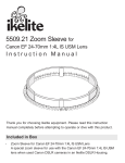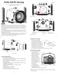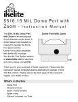
1
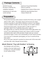
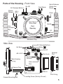
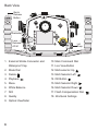
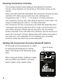
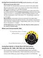
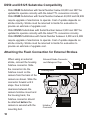
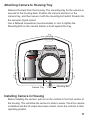
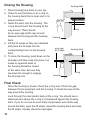
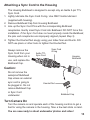
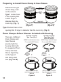
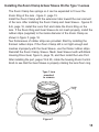
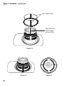
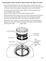
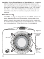
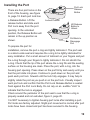
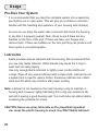
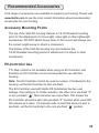
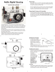
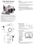
SLR-DC Housing
instruction manual
6808.1 Nikon D80
IKELITE
Thank you for your purchase of Ikelite equipment. Please read this
instruction manual completely before attempting to operate or dive
with this product. Please refer to the back page of this manual to
register your Ikelite product.
Table of Contents
Specifications ..............................................................P. 3
Package Contents ........................................................P. 4
Preparation ..................................................................P. 4
Attach External “Tray with Handles” to Housing ............P. 4
Parts of the Housing - Front/Side View ..........................P. 5
Parts of the Housing - Back View ..................................P. 6
Initial Camera Setup........................................................P. 7
Opening the Housing ......................................................P. 7
Housing Conversion Circuitry..........................................P. 8
Setting the Conversion Circuitry Strobe ID Switch..........P. 8
Using the Conversion Circuitry........................................P. 9
Using Non-Ikelite or Ikelite Non-DS Substrobes ............P. 9
DS50 and DS125 Substrobe Compatibility ....................P. 10
Attaching the Flash Connection for External Strobes ....P. 10
Attach Camera to Housing Tray ......................................P. 11
Installing Camera in Housing ..........................................P. 11
Closing the Housing ........................................................P. 12
Final Check ....................................................................P. 12
Attaching a Sync Cord to the Housing ............................P. 13
Turn Camera On..............................................................P. 13
Zoom Clamp & Gear Sleeve Installation ........................P. 14
Manual Focusing ............................................................P. 18
Installing the Port ............................................................P. 19
Lens Ports ......................................................................P. 20
Attaching an Ikelite Strobe Arm to the Housing Handle..P. 21
2
Table of Contents - continued
Usage ............................................................................P. 22
Pre-Dive Your System ....................................................P. 22
Lubricants ........................................................................P. 22
Troubleshooting
........................................................P. 23
Recommended Accessories
....................................P. 25
Accessory Mounting Points ............................................P. 25
EV-Controller Use............................................................P. 25
Maintenance..................................................................P. 26
Storing the Housing ........................................................P. 29
Spare Parts ..................................................................P. 29
Photo Tips ....................................................................P. 29
Technical Support ........................................................P. 30
Limited Warranty ........................................................P. 31
Returning Products for Service ................................P. 31
Product Registration ..................................................Back Cover
Specifications
Controls ..................All important camera functions are accessible. Controls
not provided for Diopter Adjustment and Flash Button.
Width ......................10in (250mm) including controls
Height ....................7.0in (178mm) including controls
Depth ......................6.5in (165mm) including controls
Weight ....................5.5lb (2595g) without tray & handles
Buoyancy ................Neutral in freshwater; Dependent on lens & port
Built-in Flash ..........No
Strobe Connection ..Ikelite digital TTL electrical bulkhead
Tray Mounting ........12-24 thread with 3in spacing (76mm)
3
Package Contents
- SLR-DC Housing
- Aluminum Tray & Dual Handles
- Envelope containing tray
installation hardware,
maintenance kit, and extra
control end tips.
- Silicone Lubricant
- Standard Zoom Clamp & Sleeve Set
- #5509.28 Large Diameter Zoom
Clamp & Sleeve Set
Preparation
This product has been water pressure tested at the factory and is depth
rated to 200 ft. (60m). Thoroughly inspect and immerse the empty
housing completely in water before installing a camera. If any fogging
occurs or droplets of water enter the housing, do not install a camera.
Clean the housing main o-ring and retest to make sure that it is
watertight. Refer to the Troubleshooting section, page 23.
We suggest that you read this instruction booklet thoroughly before use
to have a full understanding of where each camera control is located,
and what function each control provides. Please read your camera
manual thoroughly to have a full understanding of each camera function.
If you are new to underwater photography, be sure to read the Photo
Tips section.
Due to the power required to operate the camera and LCD screen start
each dive with a fully charged camera battery.
Attach External “Tray with Handles” to Housing
Use hardware and instructions
located in the clear Ikelite pouch
to attach the “Tray with Handles”
to your Ikelite housing.
4
IKELITE
Port Lock
Parts of the Housing - Front View
AF, Release Buttons
On-Off
Shutter AE-L,
Release AF-L
Quick Release
Strobe Arm
Mount
Flash Mode
Zoom
IKELITE
Port Lock
Gear Sleeve
Drive Gear
Subcommand
Dial
Handle
Port
Opening
Lid
Snap
Aluminum Tray
Side View
AF, Release Buttons
Meter,
Lid Snap
On-Off
AE-L /AF-L
Main Housing
O-ring
Port Lock
Optional
Port
Shutter
Release
Sub-command
Dial
Camera Tray
Gear
Sleeve
Port O-ring
Camera Mounting Bolt
Leveling Screw (Factory Pre-set)
5
Back View
Quick
Release
Button
2
3
4
Bracketing
Lens
Release/
AF-M
5
1
6
7
8
1. External Strobe Connector and
Waterproof Cap
10
4
9
11
12
13 14 15
16
18
17
TTL
-1
1
F
-3
-1 MAN -2
Lid
Snap
10. Main Command Dial
11. Live View Button
2. Mode Dial
12. Multi-selector Up
3. Delete
13. Multi Selector Left
4. Playback
14. OK Button
5. Menu
15. Multi Selector Right
6. White Balance
16. Multi Selector Down
7. ISO
17. Flash Compensation Dial
8. Quality
18. Info/Quick Settings
9. Optical Viewfinder
6
Initial Camera Setup
-
Insert a fully charged battery.
-
Insert a SD or SDHC memory card.
-
Set Time Zone and Date.
-
Set the Mode dial to “M” manual or “A” aperture priority.
-
Set shutter speed to 1/60th second or 1/125th second for fast
moving subjects in “M” mode. In “A” mode shutter speed is automatically
locked at 1/60 second.
-
Set aperture to F8 for general photography or F22 for macro
photography (close-ups).
-
Set red-eye reduction and “FP” to OFF in the Menu Settings.
-
Set image resolution to highest jpeg setting or RAW.
-
Set ISO to 100.”
-
Set Metering to “center-weighted.”
Opening the Housing
Lid Snaps have a Lock. To open,
push Lid Snap Lock forward and lift as
shown. Keep pressure on the Lid
Snap so it does not fly open quickly.
Push Forward
Lid Snap Lock
Lid Snaps have a lot of spring tension
once they go over center, so have a Lift
firm grip on the Lid Snap. Lid Snaps
may be opened one at a time.
7
Housing Conversion Circuitry
This housing contains Ikelite designed and patented Conversion
Circuitry. Once attached, turn the strobe on first before turning on the
camera.
When used with Ikelite DS Substrobes the Conversion Circuitry provides
real Nikon iTTL flash exposure with over and underexposure
compensation from +1 1/3 to - 1 1/3 f-stops in 1/3 stop increments.
The Conversion Circuitry also offers Manual exposure control with 3 1/2
f-stops of underexposure control in 1/2 stop increments.
The Conversion Circuitry is powered by the Ikelite DS Substrobe when
connected to the housing with the 4103.51 single or 4103.52 dual sync
cord. When using two strobes with the dual sync cord, the primary
strobe connected to the cord without the red band, must be turned on to
power the Conversion Circuitry. Always keep both strobes connected to
your dual sync cord underwater. Do not exchange your secondary
strobe for a dust cap which may not be waterproof.
Setting the Conversion Circuitry Strobe ID Switch
On the inside of the housing back is a switch
for setting the DS Substrobe ID. Set the
switch to the Model of DS Substrobe being
used.
When using dual strobes of different models
such as a DS51 and a DS161, set the ID
switch to DS51 or the smaller strobe.
Strobe ID Switch
DS
125
160/ 161
200
DS
50/51
80
Set DS Substrobes
to TTL Mode
ikelite
8
Using the Conversion Circuitry (Set DS Substrobe to TTL mode)
-
-
-
Mode and Compensation Dial
Note that the TTL compensation values are located in the yellow band.
Manual compensation values are located in the black band. Rotate the
Dial to switch between TTL and Manual Modes.
TTL Mode compensation values are indicated in the yellow band. Place
the Setting Indicator to TTL for NO Compensation. Rotate the Dial either
direction to select +/- compensation. Place the Setting Indicator to the
desired compensation value. Note that in TTL, compensation values are
in 1/3 f-stops.
Manual Mode compensation values are indicated in the black band.
Rotate the Dial to place the Setting Indicator to the desired compensation
value. Note that in Manual Mode, compensation values are in 1/2 f-stops
from (F) full power to -3 f-stops.
Set DS Substrobe to TTL mode. This will allow the strobe power to
be varied in manual mode.
Mode and Compensation Dial
TTL Flash Scale (yellow = 1/3 stops)
TTL
Setting Indicator
-1
1
F
-3
Manual Flash Scale (black = 1/2 stops)
-1 MAN -2
Using Non-Ikelite or Ikelite Non-DS Substrobes
(Substrobe 50, 100A, 200, 400) with this Housing
The Conversion Circuitry is automatically disabled when used with a
Non-Ikelite or Non-DS Substrobe. These Substrobes can be used in their
manual mode utilizing any power settings provided on the Substrobe.
9
DS50 and DS125 Substrobe Compatibility
-
-
Older DS50 Substrobes with Serial Number below 63,850 can NOT be
updated to operate correctly with the latest TTL conversion circuitry.
Older DS50 Substrobes with Serial Number between 63,850 and 69,999
require upgrade of electronics to operate. Cost of update depends on
strobe circuitry. Strobe must be returned to Ikelite for evaluation to
provide an estimate of upgrade cost.
Older DS125 Substrobes with Serial Number below 2,500 can NOT be
updated to operate correctly with the latest TTL conversion circuitry.
Older DS125 SubStrobes with Serial Number between 2,500 and 4,999
require upgrade of electronics to operate. Cost of update depends on
strobe circuitry. Strobe must be returned to Ikelite for evaluation to
provide an estimate of upgrade cost.
Attaching the Flash Connection for External Strobes
When using an external
strobe, connect the housing
hotshoe connector. Slide
the connector into the
hotshoe mount on the
camera from the back of the
camera as shown. Slide the
connector forward until it
stops. Due to limited
clearance between the
camera hotshoe mount and
the housing back, the
hotshoe connector should
be attached before the
camera is secured with the
mounting bolt.
10
External Strobe Connector
and Waterproof Cap
Housing Back
Hotshoe
Connector
Attaching Camera to Housing Tray
Remove the back from the housing. The mounting tray for the camera is
secured to the housing back. Position the camera and lens on the
camera tray, and then secure it with the mounting bolt which threads into
the camera’s tripod socket.
Use a flathead screwdriver (recommended) or coin to tighten the
Mounting Bolt so the camera bottom is flush against the tray.
Nikon
D90
Camera Tray
Mounting Bolt
Installing Camera in Housing
Before installing the camera, pull out on the controls in the front section of
the housing. This will allow the camera to slide in easier. Once the camera
is installed and the lid snaps have been closed, return the controls to their
operating position.
11
Closing the Housing
1. Place housing face down in your lap.
2. Check to see that there is an o-ring on
the housing back that is clean and in its
proper location.
3. Guide the back onto the housing. The
o-ring should touch the housing all the
way around. There should
be an even gap all the way around
between the housing and the housing
back.
4. Lift the lid snaps so they are extended
and place the lid snap into the
corresponding hook on the housing
back.
5. To close the housing, push down on the
lid snaps until they snap into place. Lid
snaps on opposite sides of
the housing should be closed
at the same time. Be sure they
are down far enough to engage
the lid snap lock.
housing back
o-ring
housing
even gap
all 4 sides
housing back
o-ring
housing
Final Check
Once the housing is closed, check the o-ring seal. Check the gap
between the housing back and the housing. It should be even all the
way around the housing.
Look through the clear plastic back at the o-ring. You should see a
darkened area where the o-ring is compressed against the housing
back. If you do not see an even black compression seal all the way
around the back, open the lid snaps, reseat the housing back and close
the lid snaps. Visually check the seal again.
12
Attaching a Sync Cord to the Housing
1.
2.
3.
4.
The Housing Bulkhead is designed to accept only an Ikelite 5-pin TTL
Sync Cord.
Lightly lubricate the Sync Cord O-ring. Use ONLY Ikelite lubricant
(supplied with housing).
Remove Bulkhead Cap from Housing Bulkhead.
Line up the Sync Cord Pins with the corresponding Bulkhead
receptacles. Gently insert Sync Cord into Bulkhead. DO NOT force this
installation. If the Sync Cord does not seat properly inside the Bulkhead,
the pins and receptacles are improperly aligned (repeat Step 3).
Tighten the Knurled Nut snugly using your Index finer and thumb. DO
NOT use pliers or other tools to tighten the Knurled Nut.
Always remove the
Sync Cord from your
Housing when not in
use, and replace the
Bulkhead Cap.
Ikelite TTL
Sync Cord
Sync Cord
O-ring
Housing
Bulkhead
Caution:
Do not remove the
waterproof Bulkhead
Cap unless an external
sync cord is going to
be plugged in. Do not
remove Bulkhead Cap
or Sync Cord
underwater.
Knurled Nut
Bulkhead Cap
Turn Camera On
Turn the camera on and operate each of the housing controls to get a
feel for using the camera in the housing. Take a few test shots on land.
You are now ready to shoot underwater photos and video!
13
Preparing to Install Zoom Clamp & Gear Sleeve
Determine the type
of lens being used
on the camera.
Type 1 Lenses have
a lens opening that
is NOT larger in
diameter than the
zoom ring. (Fig. 1).
lens
opening
zoom
ring
Type 1 lens
(Figure 1)
bayonet
mount
Type 2 lens
(Figure 2)
Type 2 Lenses have a lens
opening that IS larger in diameter than the zoom ring. (Fig. 2).
Zoom Clamps & Gear Sleeves Included with Housing
There are 2 different
Zoom Clamps and
Gear Sleeves
provided with the
housing. Start with
the suggested Zoom
Clamp and Gear
Sleeve depending
on the Type of
lens being used.
See (Fig. A or B)
14
Normally used with
Type 1 lens (Fig.1)
#9059.8 small diameter clamp:
For use with #0073 sleeve
wide
grooved
extension
tabs
+
thick ribs
Normally used with
Type 2 lens (Fig.2)
#5509.28 Package
#9059.9 large diameter clamp:
For use with #0073.1 sleeve
narrow
grooved
extension
tabs
+
thin ribs
#0073 sleeve: Use with
small diameter zoom clamp
#9059.8
#0073.1 sleeve: Use with
large diameter zoom clamp
#9059.9
Figure A
Figure B
Installing the Zoom Clamp & Gear Sleeve On the Type 1 Lenses
The Zoom Clamp has springs so it can be expanded to fit over the
Zoom Ring of the lens - figure C, page 15.
Install the Zoom Clamp with the extension tabs toward the rear element
of the lens. After installing the Zoom Clamp and Gear Sleeve - figures D
& E, page 16, install the Lens Port and rotate the Zoom Ring on the
lens. If the Zoom Ring and Gear Sleeve do not mesh properly, install the
rubber strips (supplied) to the inside diameter of the Zoom Clamp as
shown in figure F, page 16.
Two thicknesses of rubber strips are provided. Start by installing the
thinnest rubber strips. If the Zoom Clamp still is not tight enough and
meshes improperly with the Gear Sleeve, use the thicker rubber strips.
Reinstall the Zoom Clamp, Sleeve. Mesh Gear Sleeve teeth with Black
Housing Drive Gear, figure G, page 18, and then install the Lens Port.
After installing the port, pages 19 & 20, rotate the housing Zoom Control
Knob to see that the Gear Sleeve is properly rotating the lens Zoom ring.
Type 1 lens
mounted
to camera
zoom
ring
Figure C
15
Type 1 Lenses - continued
Gear Sleeve Ribs
Align Ribs with
Zoom Clamp
grooved tabs
Figure D
apply
rubber strips
to inside of
clamp
Figure E
16
Figure F
Installing the Zoom Clamp & Gear Sleeve On Type 2 Lenses
Due to the larger diameter lens opening on Type 2 lenses, the Zoom
Clamp and Gear Sleeve need to be installed from the rear (bayonet end)
of the lens. Use the housing Lens Release Control and remove the
camera lens from the camera body, after the camera and lens have
been installed in the housing.
Place the Gear Sleeve in the housing opening as shown.
Install the black Zoom Clamp on the Lens Zoom Ring and lower the lens
into the housing opening. Make sure the Zoom Clamp grooved tabs
align with the Gear Sleeve ribs. If necessary, install rubber strips to
expand the Zoom Clamp so it meshes properly with the Gear Sleeve.
Bayonet lens into camera body and align Gear Sleeve teeth with Black
Housing Gear Teeth.
Type 2 lens
Lens Zoom Ring
Lens Manual
Focus Ring
Zoom Clamp
Gear Sleeve
TOP OF HOUSING
Align
Zoom Clamp
grooved
tabs with
Gear Sleeve
Ribs
17
Installing Zoom Clamp/Sleeve on Type 2 Lenses - continued
Before installing the lens port and checking operation, make sure the
teeth on the Gear Sleeve mesh with the teeth on the housing Drive Gear,
shown below. When the port is installed, pages 19 & 20, it will lock the
Gear Sleeve in place. After installing the port, rotate the housing Zoom
Control Knob to see that the Gear Sleeve is properly rotating the Lens
Zoom ring.
Manual Focusing
Ikelite DSLR housings are designed for auto-focus DSLR cameras and
lenses. Manual focusing is not recommended. In some cases, if you
desire to manually focus a lens, the zoom clamp must be moved onto
the lens Manual Focus Ring and you must use the housing zoom control
knob to manually focus. This will result in loss of zoom capability.
IKELITE
Figure G
Port Lock
Release
Button
Port Lock
Mesh
Gear Sleeve
teeth with
Black
Housing
Drive Gear
18
Installing the Port
There are four port locks on the
front of the housing, see figure
G, page 18. Each port lock has
a Release Button. Lift the
release button and slide each
Port Lock away from the port
opening. In the unlocked
position, the Release Button will
remain in the up position as
shown.
Port Lock
Release
Button
Locked Position
Lift Release
Button to
Unlock
Pull Back to
Disengage
Port
To prepare the port for
installation, remove the port o-ring and lightly lubricate it. The port seal
is a side-to-side seal and requires the o-ring to be lightly lubricated for
easy installation. Put a small amount of lubricant on your fingers and pull
the o-ring through your fingers to lightly lubricate it. Do not stretch the
o-ring. Check that the lip of the port where the o-ring fits and the sealing
surface on the housing are clean. Place the port, with o-ring, into the
housing port opening. Press down on the port firmly and evenly until you
feel the port slide into place. Continue to push down on the port and
push each port lock forward until the lock fully engages. It may help to
slightly rotate the port as you push in on the port lock. Visually inspect
each port lock and confirm that the Port Lock Release Button is seated
flush against the Port Lock Body. Do not rely on an audible "click" to
indicate that the lock is engaged.
Check around the perimeter of the port seal to see that the o-ring is
properly sealed and not extruded, figure 2, page 20.
It is NOT necessary to tighten housing port locks after installing a port.
Port locks are factory adjusted. Slight port movement is normal after port
locks have been closed and port has been secured to the housing.
19
Installing the Port - continued
To Remove Port
To remove the port, lift up on each Release Button and slide the port
lock away from the port.
Port Seal Inside View
If the port is installed before the camera is
inserted into the housing, look from the
inside of the housing at the port seal.
Check to see that the o-ring is properly
seated as shown in figure 1 and not
extruded as shown in figure 2.
Fig. 1
Fig. 2
Caution:
After installing the port, turn the Zoom Control knob on the housing. If the
Zoom Control is difficult to turn, the gear sleeve may be warped. If
necessary, reduce or omit any rubber installed on the Zoom Clamp, figure
F, page 16. If the Zoom Clamp is still warped, use of the 5509.28 package
may be required, see page 14.
Lens Ports
A lens port must be secured to the housing before entering the water.
Ikelite DSLR housings DO NOT come with a lens port. You must select
the correct port for each lens you will be using underwater. For complete
lens port information and compatibility with your Ikelite system, go to
www.ikelite.com.
20
Attaching an Ikelite Strobe Arm to the Housing Handle
To attach an Ikelite Arm to your Housing Handle, depress the
spring-loaded Handle Push Button until it stops. Gently slide the
pronged end of the Ikelite Arm into the hole in the top of the Handle as
shown.
When the Ikelite Arm is properly seated, the Handle Push Button will
return to its starting position.
Ikelite Arm
Housing Handle
Handle Push
Button
21
Usage
Pre-Dive Your System
It is recommended that you take the complete system into a swimming
pool before use in open water. This will give you a chance to become
familiar with the handling and operation of your housing and strobe(s).
As soon as you enter the water, take a moment and check the housing
to see that it is properly sealed. Next, check to see if there are any
bubbles on the face of the port. If there are, take your fingers and
remove them. If there are bubbles on the lens port they can produce soft
focus spots in your photographs.
Lubricants
Ikelite provides silicone lubricant with the housing. We recommend that
you use only Ikelite lubricant. Other brands may cause the o-ring to
swell and not seal properly.
Use only enough Ikelite lubricant to lightly cover control shafts and
o-rings. Wipe off any excess lubricant with a clean cloth. Lubricant is not
a sealant and is used to reduce friction. Excessive lubricant can collect
sand and dirt which may interfere with proper sealing.
Note: Lubricant is not needed on the main housing o-ring to maintain a
housing seal, however, lightly lubricating this o-ring can extend it’s life
and aid in seeing a good housing seal. Too much lube can attract debris
increasing the potential for a leak.
CAUTION: Never use spray lubricants as the propellant ingredient
can cause the plastic housing to crack. Use ONLY Ikelite lubricant.
22
Troubleshooting
Problem
Solution
Push buttons or
controls are sticky
and hard to operate
- Remove the camera and rinse the closed housing
in fresh water. Vigorously press each push button
in and out several times to release any trapped
saltwater or debris.
- Press a sticky push button all the way in and
place a small amount of lube on the small end of
the push button shaft at it’s base. Release and
operate the push button several times to distribute
the lube.
- If a control is sticky, grab the control knob, pull it
out, and then push back in. If still sticky, see the
Control Maintenance section - pages 26 & 27.
- Return housing to Ikelite for routine maintenance.
Image is over- or
under-exposed
- Check that the strobe(s) are firing when taking
a picture.
- When using an external strobe, make sure it is
turned on, set properly, and it’s battery is charged.
- Check any corded connection points.
- Adjust camera shutter speed, aperture, or
exposure compensation.
- Move closer to or further away from the subject.
Water enters the
housing
- Remove, clean and properly lubricate the main
housing and port o-rings.
- Look for hairs, dirt, or foreign debris crossing the
o-ring seal.
- Reassemble the housing without a camera
installed and pressure test or take diving.
- Return housing to Ikelite for routine maintenance.
23
Problem
Solution
Camera does not
take a picture
- Install a fully charged battery.
- A housing control is engaging a camera function
and will not allow the shutter to fire.
- There is not enough available light for the camera
to properly focus. Add a focusing light or strobe
with a built-in focusing light to your system.
- Select a center focus point in your camera menu.
Housing is hard to
close
- Make sure the camera is mounted properly on the
camera tray and housing controls are out of the
way .
Fogging occurs on
the Lens Port
- Humid air is trapped inside the housing.
The camera produces heat and may condense
any trapped moisture forming fog on the lens port.
Close the housing in an air-conditioned room or
vehicle, or in front of an air-conditioner.
- The housing should not be in direct sunlight for an
extended period of time.
- Purchase desiccant packs from a local camera
store and place one or two packs in your housing
before each day of diving.
- If water droplets or moisture is present around the
controls or sealing areas, return the housing to
Ikelite for evaluation.
- Clean the main housing o-ring, port o-ring, and
sealing surfaces of the housing.
Pictures are too blue - Use custom (manual) white balance if available.
or too green
- Add an external strobe.
- Move in closer to your subject when taking a
picture.
24
Recommended Accessories
A full range of accessories are available to support your housing. Please visit
www.ikelite.com to see the most current information about recommended
accessories for your housing.
Accessory Mounting Points
The top of the SLR-DC housing features a 1/4-20 threaded mounting
point for the attachment of a focus light, video light or other lightweight
accessories. DO NOT attach heavy items to this mount and always use
the correct length screw to attach a component.
The bottom of the SLR-DC housing tray also features five
1/4-20 threaded mounting points for attachment of a tripod or other
accessories.
EV-Controller Use
TTL flash control is not available when using an EV-Controller, and
therefore an EV-Controller is not recommended for use with this
housing.
Note: The EV-Controller cannot be used as a slave. If hardwired to the
housing, set the EV-Controller to Non pre-flash.
The EV-Controller used with Ikelite DS Substrobes has two user
settings. One setting is for strobe selection, the other is for pre-flash “P”
or non pre-flash “ P .” Most cameras use a pre-flash. This means the
EV-Controller should be set to the pre-flash “P” position when used with
this camera as a slave. If a manual mode is used that does not emit a
pre-flash, set the EV-controller to the non pre-flash “ P ” position.
25
Maintenance
Control Maintenance
-
-
-
26
Ikelite controls are designed to provide years of reliable service with
minimal maintenance.
Push button controls require no maintenance other than rinsing in fresh
water after saltwater use. If a push button control becomes difficult to
push or if it sticks when depressed, soak the housing in luke warm fresh
water. After a few minutes, operate the push button. If this does not
correct the problem, return the housing to Ikelite for maintenance.
Some of the controls have long shafts. These controls can be pulled out,
exposing the shaft, diagram B, page 27.
To lubricate the control, gently pull on the knob until the stainless steel
shaft is exposed. Lightly lubricate the shaft, then move the shaft in and
out several times. This will lubricate the x-ring in the Ikelite control gland.
This should be done before using the housing after a prolonged storage
period, or once a week when the housing is in constant use.
Some of the controls have a short shaft and cannot be pulled out
exposing the shaft for lubrication. In the unlikely event one of these
controls sticks or becomes difficult to operate you can remove the
control from the housing and lubricate it, or return the housing to Ikelite
for maintenance. To remove the control, diagram A, page 27, loosen the
set screw in the knob (allen wrench required); remove the knob. If there
is salt or dirt build-up on the exposed control shaft, clean the shaft.
Open the housing and gently slide the control shaft out of the control
gland. Clean and lightly lubricate the shaft, including the end of the
shaft. Slide the shaft back into the control gland and gently slide it back
and forth a few times without fully removing the shaft from the gland.
Replace the knob noting the flat area on the shaft. The set screw in the
knob should tighten down against the flat area on the control, so the
knob does not turn on the shaft.
Diagram A
Housing
Gland
Control Shaft
Tighten set screw down
against this flat area
when replacing the knob.
Lubricate end of shaft
before reinserting into
gland
Loosen set screw
(allen wrench required)
Diagram B
Lubricate Shaft
Housing
Pull out to
expose shaft
27
Housing Maintenance
-
-
-
-
Your Ikelite Housing should be given the same care and attention as
your other photographic equipment. In addition to normal maintenance,
we recommend your housing be returned to Ikelite (every 2-3 years or
50 dives), to be checked and pressure tested.
Do Not leave the camera and housing in direct sunlight for prolonged
periods. Heat may damage the camera.
Do Not ship the camera in the housing.
Before using the housing, always check the tightness of the set screw
in each control knob.
Check each control gland penetrating the housing to make sure they
are tight. There is a slight chance that either could vibrate loose during
travel.
Keep the back and port o-ring clean and lightly lubricated. To lubricate,
remove the o-ring from the back. Put a small amount of lkelite lubricant
on your fingers. Pull the o-ring through your fingers to apply a light
coating of lubricant. Only apply enough lubricant to make the o-ring feel
slick. Do Not stretch the o-ring. This light coating of lubricant will help
to keep the o-ring from drying out and will help to show a dark sealing
line when the housing back is properly sealed.
Keep the area where the o-ring fits and the sealing surface clean.
Rinse the housing exterior thoroughly in freshwater after each saltwater
use. Depress push buttons several times during rinse. Dry with a soft
cloth. Dry port to eliminate water spotting.
After several uses in saltwater, soak the housing in a mild soap solution,
rinse, and dry.
Although not recommended, if it is necessary to remove a housing push
button, Do Not re-use the E-clip. Contact Ikelite for replacement E-clips
(part #0319.12).
CAUTION: Never use spray lubricants as the propellant ingredient can
cause the plastic housing to crack. Use only Ikelite lubricant.
28
Storing the Housing
When the housing is going to be stored for a prolonged period it should
be soaked in a mild soap solution, rinsed, and dried thoroughly. Remove
the back and port from the housing. Remove the back and port o-rings,
lightly lubricate them and place them in a plastic ziploc bag. Place the
plastic bag inside the housing for storage. Operate the push buttons
periodically.
Spare Parts
0132.59 ............Spare Main Housing O-ring
0105 ................Spare Port-to-Housing O-ring
5020 ................Silicone Lubricant in 4 1cc Tubes
5512.68 ............O-ring Kit with Main O-ring, Port O-ring, & 1cc Lubricant
0333.6 ..............Tray Mounting Screw 12-24 x 1/2 in. Stainless
0212.12 ............1/4 in. Shoulder Washer for 12-24 Screw
9104.5 ..............Waterproof Bulkhead Cap
0200.91 ............Body Cap
Photo Tips
-
-
The number one rule in underwater photography is to eliminate as much
water between the camera and subject as possible. Get as close as you
can to the subject, then use the zoom. If you are using flash for still
photos, subjects beyond 6 feet (1.8m) will not have much color
regardless of strobe power.
Photograph in clear water; do not stir up the sand or silty bottom. If
backscatter becomes a problem in the environment you are
photographing, an external flash will help eliminate much of the
backscatter.
29
Photo Tips - continued
-
-
-
-
-
Many digital cameras have a slight lag time between when you press
the shutter release button and the camera actually takes the picture.
Hold the housing steady a second or two after pressing the shutter
release button.
Do not shoot down on subjects as they will quite often blend into the
background and be difficult to see in the photograph. Shoot subjects
straight on or shoot up at a slight angle using the blue water as a
contrasting background.
When using daylight or flash, if your camera consistently over or
underexposes the image, you may want to adjust your camera’s
exposure compensation
settings.
If you error in exposure, it is better to have the image slightly
underexposed rather than overexposed. An overexposed image is
missing color information which cannot be adjusted in a photo
processing program. A slightly underexposed image has color
information that can be adjusted.
It is important to respect all living creatures underwater, including
people, marine life, and coral. While we encourage people to get close
to their subjects when taking a photograph, they should not touch, lie on,
or in any way disturb the things they find underwater.
Technical Support
Please read the troubleshooting section of this instruction manual before
contacting Ikelite Technical Support.
Ikelite Technical Support
Email: [email protected]
Phone 317.923.4523
Fax 317.924.7988
30
Limited Warranty
This Ikelite product is warranted against any manufacturing defects for a
period of one (1) year from the original date of purchase. Defective
products should be returned to Ikelite postage paid. Ikelite will, at its sole
discretion, repair or replace such products, and will return to customer
postage paid. All other claims of any nature are not covered. Except as
mentioned above, no other warranty expressed or implied applies to this
Ikelite product.
Returning Products For Service
Ikelite is most interested in performing any service to ensure that all
products perform as intended. Evidence of purchase date must be
provided to obtain warranty service.
No prior authorization is required. You may return directly to us or
through your dealer. Please include a brief description of the problem,
any relevant email correspondence, and/or instructions on what you
want us to do. Always include name, shipping address, email address,
and phone number inside of the package. Send postage paid to:
Ikelite Underwater Systems
Attention: Service Department
50 West 33 Street
Indianapolis, IN 46208 USA
No reimbursements for postage paid will be issued.
You may also want to insure the package.
Returning Products for Service (outside the United States)
For the separate international customs documentation form that you
complete to accompany the shipment, please state or designate that the
enclosed products were originally manufactured in the USA and are
being returned to the manufacturer for repair service. Value of the
equipment listed for customs purposes should be zero.
31
Product Registration
Please go to www.ikelite.com to register your Ikelite housing within 15
days of purchase.
Ikelite Underwater Systems
50 West 33rd Street
Indianapolis, IN 46208 USA
www.ikelite.com
6808.1_Nikon_D80_03-0712