1
X
XS26GS
Ma
anaged Optic
cal Ethernett Switch Use
er Manual
XS2
26GS
Managed Optica
al Ethe
ernet S
Switch
h
User Manu
ual
June 15,20
011
Version: 1.0
01
http:///www.xeny
ya.si
XS26GS Managed Optical Ethernet Switch User Manual
Copyright © 2010-2011, XENYA d.o.o.
All Rights Reserved
This document contains proprietary information that is protected by copyright. No part
of this document may be reproduced, transmitted, transcribed, stored in a retrieval
system, or translated into any language, in any form or by any means, electronic,
mechanical, magnetic, optical, chemical, manual or otherwise without the prior written
permission of Xenya d.o.o.
Disclaimer Notice:
No license is granted, implied or otherwise, under any patent or patent rights of
XENYA d.o.o. makes no warranties, implied or otherwise, in regard to this document and
to the products described in this document. The information provided by this document
is believed to be accurate and reliable to the publication date of this document. However,
Xenya d.o.o. assumes no responsibility for any errors in this document. Furthermore,
Xenya d.o.o. assumes no responsibility for the use or misuse of the information in this
document and for any patent infringements that may arise from the use of this
document. The information and product specifications within this document are subject
to change at any time, without notice and without obligation to notify any person of such
change.
i
XS26GS Managed Optical Ethernet Switch User Manual
Table of Contents
1. Introduction .............................................................................. 5
1.1 FEATURES ...................................................................................................5
1.2 FACE PANEL .................................................................................................2
1.3 SFP BASED OPTICAL INTERFACE OPTIONS .............................................................2
1.4 POWER SUPPLY OPTIONS .................................................................................2
1.5 PHYSICAL AND ENVIRONMENTAL .........................................................................2
1.6 DEFAULT CONFIGURATION ................................................................................3
1.7 MANAGEMENT SOFTWARE SPECIFICATION ..............................................................4
2. Web Management Function ....................................................... 5
2.1 CONVENTIONS ..............................................................................................5
2.2 SYSTEM INFORMATION ....................................................................................5
2.3 ADVANCED CONFIGURATION ..............................................................................6
2.4 PORT MANAGEMENT .......................................................................................6
2.4.1 Port Configuration ...............................................................................7
2.4.2 Port Aggregation .................................................................................7
2.4.3 Port Bandwidth ...................................................................................9
2.4.4 Port Mirroring ................................................................................... 10
2.5 VLAN ..................................................................................................... 11
2.5.1 Advanced ......................................................................................... 11
2.5.2 Port-based VLAN ............................................................................... 11
2.5.3 802.1Q VLAN .................................................................................... 11
2.5.4 Protocol VLAN ................................................................................... 13
2.5.5 MAC-based VLAN .............................................................................. 13
2.5.6 VLAN VPN ........................................................................................ 14
2.5.7 GARP ............................................................................................... 16
2.6 QOS ....................................................................................................... 16
2.6.1 QoS Configuration ............................................................................. 17
2.6.2 Scheduling Mechanism ....................................................................... 17
2.6.3 Transmit Queues ............................................................................... 18
2.6.4 DSCP Map ........................................................................................ 18
2.7 FORWARDING ............................................................................................. 19
2.7.1 Unicast MAC Address ......................................................................... 19
2.7.2 Multicast MAC Address ....................................................................... 20
2.7.3 IGMP Snooping ................................................................................. 21
2.7.4 MVR ................................................................................................ 22
2.7.5 Unknown Multicast ............................................................................ 23
2.8 SECURITY ................................................................................................. 24
2.8.1 Management Security ........................................................................ 24
2.8.2 Port Authentication ............................................................................ 24
2.8.3 MAC Authentication ........................................................................... 27
2.8.4 IP Binding ........................................................................................ 28
2.8.5 Storm Control ................................................................................... 28
2.9 ACL ....................................................................................................... 28
2.9.1 Management ACL .............................................................................. 29
2.9.2 ACL Rule .......................................................................................... 29
2.9.3 Port Binding...................................................................................... 32
2.10 LLDP .................................................................................................... 32
2.10.1 Management LLDP ........................................................................... 32
2.10.2 Neighbor Information ....................................................................... 34
2.10.3 LLDP Statistics ................................................................................ 34
2.11 STATISTICS ............................................................................................. 36
2.11.1 Port Status ..................................................................................... 36
2.11.2 Port Statistics ................................................................................. 36
2.11.3 VLAN List ....................................................................................... 37
2.11.4 MAC Address Table .......................................................................... 37
ii
XS26GS Managed Optical Ethernet Switch User Manual
2.11.5 IGMP Snooping Group ...................................................................... 38
2.11.6 Link Aggregation ............................................................................. 38
2.12 SPANNING TREE ........................................................................................ 39
2.12.1 Global ............................................................................................ 39
2.12.2 STP&RSTP ...................................................................................... 40
2.12.3 MSTP Region ................................................................................... 43
2.12.4 MSTP Ports ..................................................................................... 45
2.12.5 MSTP State ..................................................................................... 46
2.13 SNMP MANAGER....................................................................................... 46
2.13.1 SNMP Account ................................................................................. 46
2.13.2 SNMP Trap ...................................................................................... 48
2.14 ADMINISTRATION....................................................................................... 49
2.14.1 IP Configuration .............................................................................. 49
2.14.2 Ping Diagnosis ................................................................................ 50
2.14.3 Account .......................................................................................... 50
2.14.4 TFTP Services ................................................................................. 51
2.14.5 Reboot ........................................................................................... 52
2.14.6 Reset ............................................................................................. 52
2.14.7 Save Configuration .......................................................................... 53
2.14.8 System Logs ................................................................................... 53
2.15 LOGOUT ................................................................................................. 54
3. Command Line Interface (CLI) ................................................ 55
3.1 ERROR MESSAGE ....................................................................................... 55
3.2 CLI CONVENTIONS ...................................................................................... 55
3.3 SHORTCUTS INTRODUCTION ............................................................................ 55
3.4 CLI COMMAND MODES .................................................................................. 56
3.5 GLOBAL COMMANDS ..................................................................................... 57
3.6 USER LEVEL .............................................................................................. 57
3.7 SYSTEM MANAGEMENT COMMANDS .................................................................... 58
3.8 PORT BASIC CONFIGURATION COMMANDS ............................................................ 70
3.9 LINK AGGREGATION COMMANDS ....................................................................... 78
3.10 MIRRORING COMMANDS ............................................................................... 85
3.11 VLAN COMMANDS ..................................................................................... 87
3.11.1 VLAN Configuration Commands ......................................................... 87
3.11.2 Port-Based VLAN Configuration Commands ......................................... 98
3.12 VLAN VPN ........................................................................................... 101
3.13 GVRP COMMANDS ................................................................................... 103
3.14 QOS COMMANDS ..................................................................................... 107
3.15 MAC ADDRESS TABLE MANAGEMENT COMMANDS ............................................... 113
3.16 MULTICAST COMMANDS ............................................................................. 118
3.17 IGMP SNOOPING CONFIGURATION COMMANDS .................................................. 120
3.18 802.1X CONFIGURATION COMMANDS ............................................................. 126
3.19 STP COMMANDS ..................................................................................... 133
3.20 SNMP CONFIGURATION COMMANDS .............................................................. 149
3.21 SYSTEM LOG COMMANDS ........................................................................... 157
3.22 LLDP CONFIGURATION COMMANDS ............................................................... 158
3.23 ACL CONFIGURATION COMMANDS ................................................................. 164
3.24 PORT BINDING CONFIGURATION COMMANDS ..................................................... 166
3.25 MVR CONFIGURATION COMMANDS ................................................................. 168
3.26 LOOPBACK-DETECTION .............................................................................. 172
4. Ordering Information ............................................................ 176
5. Appendix A: Command Index ................................................ 177
6. Appendix B: Supported MIBs ................................................. 184
iii
XS26GS Managed Optical Ethernet Switch User Manual
REVISION HISTORY
Date
Jan 28, 2011
Jun 15, 2011
Version
V1.00
V1.01
Description
Initial release
Graphics update
iv
XS26GS Managed Optical Ethernet Switch User Manual
1. Introduction
XS26GS Managed SFP Based Optical Ethernet Switch is a high-performance
managed Layer 2+ Gigabit Ethernet switch for service providers. It offers up to
twenty-six SFP based Gigabit Ethernet fiber optic ports.
XS26GS is targeted at the emerging market of Ethernet based FTTx. It comes with
a rich feature set to meet the requirements of a wide range of applications, especially
the access network and the small-to-medium-scale customized network. The design of
dual power supply provides the power redundancy for applications requiring high
reliability. XS26GS is low-profile with a standard rack-mount size. It achieves the
highest fiber port density within a single rack, providing users with the best
performance/price ratio.
1.1
z
z
z
z
z
z
z
z
z
z
z
z
z
z
z
z
z
z
z
z
z
z
z
z
z
z
z
z
z
z
Features
A range of configurable copper and fiber ports to meet the requirement of
various applications, such as FTTH, optical LAN, Ethernet-based DCS and
security surveillance system.
8K address table for auto-learned unicast or static unicast/multicast addresses.
Jumbo frame of up to 9216 bytes
802.1p, Port, and DiffServ based QoS package classification with 4 priority
queues. Support queue mapping and DSCP mapping.
4K 802.1Q based VLAN
Port based VLAN
16 Protocol based VLAN
MAC based VLAN
Guest VLAN
VLAN VPN, QinQ
GARP/GVRP
16 trunk groups of up to 8 member ports with flexible load distribution control
and fail-over functions.
Manual, static, and dynamic port aggregation
802.1d Spanning Tree Protocol, 802.1w Rapid Spanning Tree Protocol, and
802.1s Multiple Spanning Tree Protocol.
By-port egress, ingress, and bi-direction rate control
Multi combination of MAC address, VID, and port binding
Static and dynamic MAC addressing
Blackhole MAC address filtering
IGMP Snooping
Multicast VLAN Registration (MVR)
Link Layer Discovery Protocol (LLDP)
Storm Control for any combination of multicast, broadcast, and DLF traffic
Access Control Lists (ACL)
Secure Shell (SSH) v2.0
802.1x Port-based access control and MAC authentication
User configurable port mirroring supports ingress/egress/both data flow
monitoring on one or more ports.
SNMP v1/v2c/v3
Web page management
Command Line Interface (CLI)
Telnet and RS232 console management
v
XS26GS Managed Optical Ethernet Switch User Manual
z
z
z
z
1.2
User account assignable to one of the three access privilege levels
On-line firmware upgrade
Configuration file backup and restore
Dual power supply modules provide power redundancy with status monitoring
features.
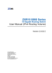
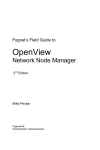
Face Panel
The face panel of the XS26GS optical Ethernet switch is shown in the following figure.
1.3
z
1.4
z
z
z
z
1.5
z
z
z
z
z
SFP Based Optical Interface Options
1000Base-X
o
Dual multimode fiber(50/125μm), single wavelength 850nm, dual LC
connector, 550m reach.
o
Dual multimode fiber(62.5/125μm), single wavelength 850nm, dual
LC connector, 275m reach.
o
Dual single-mode fiber, single wavelength 1310nm or 1550nm, dual
LC connector, 15/40 km reach.
Power Supply Options
AC90~264V/1.2A max, 50/60Hz, or
DC18~36V/2A, or
DC36~72V/1.5A
Power Consumption: no more than 45W
Physical and Environmental
Dimensions: 19-inch rack-mount width, 1.0U height
Weight: ~5Kg
Operating temperature: 0℃ ~ 50℃
Storage temperature: -25℃ ~ 85℃
Humidity: 5% ~ 95% RH Non-condensing
2
XS26GS Managed Optical Ethernet Switch User Manual
1.6
Default Configuration
(1) Administration
IP:
IP Address:
192.168.0.253
IP Sub network: 255.255.255.0
IP Gateway:
192.168.0.201
Accounts:
User Level: Visitor
User
User Name: guest
manager
Password: (none)
123
(2) Port
State:
Flow Control:
Learning:
Rate limit:
Negotiation:
enabled
disabled
enabled
disabled
enabled
(3) VLAN
VLAN mode:
Static VLAN:
Port VID:
Port link type:
Frame type:
none
1, including all ports
1
hybrid
admit all
(4) SNMP
Version:
Community:
Privilege :
User:
SNMP trap:
Trap host IP:
v1
public
RO
(none)
enabled
(none)
(5) Protocols
IGMP Snooping:
GARP/GVRP:
STP:
LACP:
802.1x:
LLDP:
Disabled
Disabled
Disabled
Disabled
Disabled
Disabled
3
Administrator
superuser
123
XS26GS Managed Optical Ethernet Switch User Manual
1.7
Management Software Specification
The following table summarizes the protocols supported by the managed optical
Ethernet switch in the current software release.
TCP/IP
SNMP
Web management server
ARP, ICMP, IP, TCP, UDP
SNMP v2(1,2,3,9), FMC private MIBS, MIB counters of
groups 1,2,4,9
Http Server. Support goahead-2.1.8.Java scripts, Java
Applet, CGI
Telnet server
Telnet 1.0
Console
Standard UART
Spanning tree protocol
IEEE 802.1d/1w/1s
Four-level priority queuing
IEEE 802.1p
Port-based VLAN
SVL
Tag-based VLAN
IEEE 802.1q (IVL and SVL), GVRP
Protocol-based VLAN
IEEE 802.1v
Trunking
IEEE 802.3ad, LACP
Authentication
IEEE 802.1x
IGMP Snooping
RFC2236
4
XS26GS Managed Optical Ethernet Switch User Manual
2. Web Management Function
A Web browser has been provided to manage and monitor the switch. The default values
are set in section 1.6 of this manual. When logging to the switch, you can browse
http://192.168.0.253 and type the user name and password as shown in section 1.6
above.
If you need to change IP address at the first time, you can modify it through RS232
console, or using telnet to login.
2.1
Conventions
Convention
Boldface
italic
<>
2.2
Description
Keywords on web management page is in Boldface
Tag page name is in italic
Button on web management page is in <>
System Information
At login, the web is on System Information page, which shows the basic information of
the switch as below.
5
XS26GS Managed Optical Ethernet Switch User Manual
2.3
Advanced Configuration
This page configures whether to globally enable or disable the following protocols:
z IGMP Snooping
z GVRP
z STP
z LACP
z Authentication
z LLDP
z LBD
z LBD Interval Time
z XS View
IGMP Snooping: globally enable or disable the protocol.
GVRP: globally enable or disable the protocol.
STP: globally enable or disable the protocol.
LACP: globally enable or disable the protocol.
Authentication: select authentication between 802.1x or MAC based, or disable the
authentication.
LLDP: globally enable or disable the protocol.
LBD: used to globally enable loopback detection function on this switch. It will check
whether there is a loop on the switch on any VLAN. If there is one on a VLAN, it will shut
down the port or will send out a trap.
LBD Interval Time: time interval for loopback detection, in the range of 5 to 300
(seconds). The default value is 30.
XS View: enable or disable the XS View management software.
2.4
Port Management
This page configures port related management functions as below:
z Port Configuration
z Port Aggregation
z Port Bandwidth
z Port Mirroring
6
X
XS26GS
Ma
anaged Optical Ethernett Switch Use
er Manual
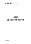
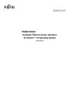
2.4
4.1 Portt Config
guration
n
p
configu
ures a port. When
W
the settup is completed, click <Apply>
<
to ta
ake effect.
This page
LBD: enables loo
opback detec
ction for the specific portt.
LBD Control: en
nable or disa
able LBD Con
ntrol for the specific portt. If the loop
pback port
contrrol function is
s enabled on a trunk or h
hybrid port when
w
a loop is
s found, the switch will
disab
ble the port, and remove
e the corresp
ponding MAC
C forwarding entries. On the other
hand,, if the loopb
back port con
ntrol function is disabled
d on a trunk or hybrid po
ort when a
loop is
i found, the port will nott be disabled
d. For an acce
ess port, the switch will disable
d
the
port if
i a loop is found,
f
as farr as LBD is e
enabled, no matter LBD Control is enabled
e
or
disab
bled.
By de
efault, the lo
oopback portt control func
ction is disab
bled on a tru
unk or hybrid
d port.
A list of the port status
s
is also
o provided. S
See the follo
owing figure for more details.
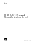
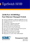
2.4
4.2
Port Aggregation
n
XS26
6GS switch su
upports up to
o 16 link agg
gregation gro
oups, and ea
ach group ca
an have up
to 8 ports.
p
This page
p
sets lin
nk aggregation. There arre three type
es of aggreg
gation: manu
ual, static,
and dynamic.
d
The
e following is
s a detailed description of
o each type of aggregattion:
Manu
ual aggrega
ation: a man
nual trunk ca
an only be manually
m
set or
o deleted; any
a
port in
a man
nual trunk sh
hall have this
s port’s Link Aggregation
n Control Pro
otocol (LACP)) disabled,
while the global LACP
L
can be either enabled or disabled.
Static LACP agg
gregation: a static LACP trunk can on
nly be manua
ally set or deleted; any
XS26GS Managed Optical Ethernet Switch User Manual
port in a static LACP trunk shall have this port’s Link LACP enabled. When a static LACP
trunk is (manually) deleted, all ports of this trunk with “up” status will generate one or
more dynamic LACP trunks automatically.
Dynamic LACP aggregation: a dynamic LACP trunk can only be set or deleted
automatically by the protocol; any port in a dynamic LACP trunk shall have this port’s
LACP enabled.
A trunk may be configured as a mirror port, but it is not allowed to configure a trunk as
a monitoring port.
There are four tag pages on this webpage to configure various parameters:
Aggregate Groups – create and configure a trunk. The switch can have up to 13 trunks.
Trunk ID: one of the 13 trunk IDs (from T1 to T13) for the user to choose from.
Trunk Name: give a name for the selected trunk.
Trunk Type: select the trunk to be a manual trunk, or static LACP trunk.
Port: choose up to 8 ports to form the trunk.
The bottom part of this tag page lists all existing trunks.
Note: Only when LACP in Advanced Configuration page is enabled, Trunk Type can be
selected; otherwise, the Trunk Type is Manual.
Lacp Port Setting – configures LACP ports
Aggregate Based Setting – sets LACP system priority, between 1 and 65535
8
XS26GS Managed Optical Ethernet Switch User Manual
Lacp Status Setting – sets LACP active or passive for each port
Active: The port automatically sends LACP protocol packets.
Passive: The port does not automatically send LACP protocol packets; it responds only
if it receives a LACP protocol packet from the opposite device.
A link having either one or two active LACP ports can perform dynamic LACP trunking. A
link has two passive LACP ports that will not perform dynamic LACP trunking as both
ports are waiting for LACP protocol packet from the opposite device.
2.4.3
Port Bandwidth
This page sets the ingress and/or egress rate limit for each port.
Port: the port for which the rate limit is configured.
Ingress: the desired ingress rate limit to be configured. Choose “disabled” to set the
port with no ingress rate limit, which means the port will run in full speed for ingress
traffic.
Egress: the desired egress rate limit to be configured. Choose “disabled” to set the port
with no egress rate limit, which means the port will run in full speed for egress traffic.
When completing a configuration, click <apply> to take effect.
The bottom part of this page shows a full list of rate limit for each port.
9
X
XS26GS
Ma
anaged Optical Ethernett Switch Use
er Manual
2.4
4.4
Port Mirro
oring
This page configures the po
ort mirroring
g function. You
Y
can sett up 1 to 4 Mirroring
ps,each grou
up can selectt one Monito
otring Port, but
b more tha
an one Morro
oring.
Group
Moniitoring Portt: the port or ports to wh
hich the trafffic is mirrore
ed
Rx Po
ort: all ingre
ess traffic of this port will be mirrored
d to each of the Monitoring Port(s)
Tx Po
ort: all egress traffic of this
t
port willl be mirrored
d to each of the Monitoring Port(s)
Rx/T
Tx Port: all ingress and egress trafffic of this po
ort will be mirrored to ea
ach of the
Monittoring Port(s
s)
X
XS26GS
Ma
anaged Optical Ethernett Switch Use
er Manual
2.5
VLAN
N
This managed sw
witch suppo
orts 802.1Q, port-based
d, mac-based
d vlan, vlan
n-vpn and
proto
ocol-based VLAN.
VLAN is disabled in default co
onfiguration.
2.5
5.1
Ad
dvanced
d
This page
p
globally
y sets the VL
LAN mode fro
om the follow
wing: no VLA
AN, 802.1Q VLAN,
V
and
port-based VLAN..
2.5
5.2
Port-based VLAN
N
On th
his page, the
e user can crreate a new VLAN
V
group with specific
c VID and VL
LAN group
name
e. Up to 256 VLAN groups
s can be crea
ated; each VLAN group can have an ID
I number
from 1 to 4094.
Mem
mber: checks
s to indicate the port is a member off the VLAN group.
The bottom
b
part of this page lists all portt-based VLAN
N groups con
nfigured.
2.5
5.3
80
02.1Q VLAN
There
e is a defaultt VLAN group
p with VLAN identifier (VID) of 1, eac
ch port is a member
m
of
this group
g
in defa
ault, and rem
mains as a m
member before it is remo
oved from the group.
e are three ta
ag pages on this webpage
e for the use
er to configurre various pa
arameters:
There
2.5.3.1 802.1Q VLA
AN
X
XS26GS
Ma
anaged Optical Ethernett Switch Use
er Manual
On th
his tag page, the user can create a new VLAN group
g
with s
specific VID and VLAN
group
p name. Up to
t 256 VLAN
N groups can be created; each VLAN group can have
h
an ID
numb
ber from 1 to
o 4094.
b
part of
o this page lists
l
all existing VLAN gro
oups, as welll as the inforrmation on
The bottom
each VLAN group. Users can also modify or delete an
n existing VLA
AN group.
Note:: It is not allowed to dele
ete VLAN gro
oup 1.
2.5.3.2 802.1Q Configuration
This tag
t
page con
nfigures a VL
LAN group; each
e
port can be configu
ured as a spe
ecific state
for th
his VLAN group:
Tagg
ged: indicate
es the port is a tagge
ed member of the VLA
AN group. All packets
forwa
arded by the port are tag
gged. The pa
ackets contain VLAN info
ormation.
Untagged: indica
ates the portt is an untagged VLAN member of the
e VLAN group. Packets
forwa
arded by the port are untagged.
Exclu
ude: exclude
es the port frrom the VLAN
N group. How
wever, the po
ort can be added to the
VLAN group throu
ugh GARP.
Forbidden: does
s not allow the port to be added to
t the VLAN group, even if GARP
indica
ates so.
2.5.3.3 802.1Q Porrt
t
page con
nfigures 802.1Q VLAN po
ort paramete
ers:
This tag
PVID
D: each port can have onlly one Port VLAN
V
ID (PVID), an untag
gged Etherne
et package
will be
b tagged a VID
V
of PVID when arriving at the po
ort. The defa
ault PVID is 1 for each
port.
Link Type: can choose Access, Trunk, or Hybrid (by defaultt) from this pull-down
block
k. An Access
s port has only
o
one VLA
AN and the tag
t
is remov
ved when eg
gress (i.e.
Untagged); a Trunk port can
n have multip
ple VLANs, and all packag
ges are tagge
ed, except
when
n an egress package
p
is in
n a VLAN gro
oup with VID the same as
s PVID; a Hy
ybrid port
is sim
milar to a Tru
unk port, exc
cept it leaves
s the user a flexibility
f
of configuring
c
e
each
port’s
Tagg
ged or Untag
gged.
X
XS26GS
Ma
anaged Optical Ethernett Switch Use
er Manual
Ingre
ess Fliter:W
When enable
ed, an Etherrnet package
e is discarde
ed if this porrt is not a
member of the VL
LAN with which this pack
kage is assoc
ciated. When
n disabled(by
y default),
all pa
ackages are forwarded
f
in
n accordance
e with the 80
02.1Q VLAN bridge specification.
me Type: ch
hooses how the port ac
ccepts Ethern
net package
e. When Adm
mit All is
Fram
selectted, the porrt accepts all ingress pa
ackages; wh
hile Admit Only
O
Tagge
ed accepts
tagge
ed packages,, and discard
ds untagged ones.
The bottom
b
part of this tag page lists the
e status of all ports.
2.5
5.4
Pro
otocol VLAN
V
ures protoco
ol VLAN. The
e pull down VID block lists all existing VLAN
This page configu
ps for users to
t choose a group
g
to con
nfigure. For a selected VL
LAN group, the Frame
group
Type
e lists all prottocols for wh
hich users ca
an choose. Ethernet Typ
pe is bundled with the
Fram
me Type cho
osen, except for Etherne
et II, for which users can
n type in an Ethernet
Type
e.Coresspond
ding Port is selected when setting Protocol VLA
AN group.
The bottom
b
part of this page lists all prottocol VLAN groups config
gured.
2.5
5.5
MA
AC-base
ed VLAN
N
p
configu
ures mac-bas
sed VLAN. T
The pull down
n VID block lists all exis
sting VLAN
This page
group
ps for the use
er to choose a group to c
configure. Fo
or a selected VLAN group, the MAC
Addr
ress is the so
ource MAC address of inc
coming pack
kets, and the
e Priority is the added
VLAN tag priority.
b
part of this page lists all mac
c-based VLAN
N groups con
nfigured.
The bottom
X
XS26GS
Ma
anaged Optical Ethernett Switch Use
er Manual
2.5
5.6
VL
LAN VPN
N
2.5.6.1 VPN Globall Setting
This page
p
enables
s or disables
s global VLAN
N VPN.
VLAN
N VPN: enab
ble or disable
e the global VLAN VPN.
2.5.6.2 VLA
AN VPN Port
es or disables
s VLAN VPN and
a
sets TPID
D (Tag Protoc
col Identifierr) value for
This page enable
a spe
ecific port. The default TPID
T
value is
s 0x8100. Be
e aware thatt some other vendors’
switches may sett this value to be 0x9100
0.
Port:: select a spe
ecific port fo
or setting.
State
e:To enale orr disable a specific port.
TPID
D: To set TP
PID value, 0x8100 by d
default. TPID
D is used to identify wh
hether the
packe
ets carry spe
ecific VLAN Tag.
T
Note tha
at the locatio
on of the TPIID field in an
n Ethernet
packe
et is the sam
me as the prrotocol type field in a pa
acket withou
ut VLAN Tag. Thus, to
preve
ent confusion
n from happ
pening, the following prrotocol type values shou
uld not be
config
gured as a TPID
T
value.
z ARP: 0x0
0806
z IP: 0x08
800
z MPLS: 0x
x8847/0x8848
z IPX: 0x8
8137
z IS-IS: 0x
x8000
z LACP: 0x
x8809
z 802.1x: 0x888E
X
XS26GS
Ma
anaged Optical Ethernett Switch Use
er Manual
2.5.6.3 Qin
nQ
QinQ is an enhanc
ced feature of
o VLAN-VPN. An Outer Ta
ag can be add
ded, which is
s based on
the in
nner Tag. In this
t
page, yo
ou can set QinQ paramete
ers as Outerr Tag VID, Inner
I
Tag
VID, Outer Tag Priority and
d Port.
Oute
er Tag VID: A VLAN ID for
f the outerr tag that willl be added tto the packet.
Inne
er tag VID(L
Low)/ Inne
er tag VID(H
High): An outer tag is added to form
m a double
tag pa
ackage, if the incoming package
p
has a VLAN ID va
alue between
n Inner tag VID(Low)
and Inner
I
tag VID(High) (a
all inclusive)).
Oute
er Tag Priorrity: the oute
er tag VLAN priority, in the
t
range of 0 to 7.
Port:: the double tag port from which a package is re
eceived.
b
part of this page lists all conffigured QinQ
Q mapping ru
ules.
The bottom
X
XS26GS
Ma
anaged Optical Ethernett Switch Use
er Manual
5.7
2.5
GA
ARP
GARP
P VLAN Registration Pro
otocol (GVRP
P) is based on Generic Attribute Re
egistration
Proto
ocol (GARP). They are sta
andard proto
ocols describ
bed in IEEE 8
802.1D.
ke sure GVRP
P is enabled (see section 2.2 of this manual
m
for
Beforre configuring GARP, mak
details). There arre two tag pa
ages:
GARP
P: this tag pa
age sets GAR
RP Join Time
e, Leave Tim
me, and Leaveall Time.. Leaveall
Time
e must be greater than Leave
L
Time,, and Leave Time must be greater than
t
twice
the Jo
oin Time.
GVRP
P: this tag page sets per port
p
GVRP pa
arameters. Fo
or a selected
d Port, enablled GVRP,
the Registration
R
n Type can be
b set to Norrmal (defaullt), Fixed, or Forbidden
n. Normal
registtration allow
ws dynamic passing,
p
regiistration, and de-registra
ation of both
h dynamic
and static
s
VLANs
s; Fixed reg
gistration allo
ows passing static VLAN
Ns, as well as
a manual
registtration, de-re
egistration of
o VLANs; wh
hile Forbidde
en prohibits the port from
m passing,
registtration, or de
e-registration of VLANs.
The bottom
b
part of GVRP tag page lists th
he GVRP attrribute of all ports.
2.6
QoS
m
sw
witch supportts Quality of Service (Qo
oS).
This managed
X
XS26GS
Ma
anaged Optical Ethernett Switch Use
er Manual
QoS priority
p
is dis
sabled in deffault configu
uration.
2.6
6.1
Qo
oS Conffiguratio
on
This tag
t
page sets
s per port Qo
oS paramete
ers. For a sele
ected Port, set the Priority, with
DSCP
P enabled, th
he Default Priority
P
can
n be set from
m 0-7.
b
part of
o QoS Configuration tag
g page lists the
t
default priority
p
of all ports and
The bottom
the sttate of DSCP
P.
2.6
6.2
Sc
chedulin
ng Mech
hanism
This page
p
sets the queue scheduling algo
orithm and re
elated param
meters.
Sche
eduling Mec
chanism can be set to Strict Priority or Weighted Round-Robin
(WRR
R).
Strict Priority: uses
u
the strict priority (S
SP) algorithm
m for queue scheduling.
ghted Round-Robin (W
WRR): uses tthe weighted
d round robin (WRR) algorithm for
Weig
queue
e scheduling
g.
WRR
R Queue Priiority Weig
ght: customizes the weiights to be assigned to queues 1
throu
ugh 4. The va
alue ranges from 1 to 55
5.
X
XS26GS
Ma
anaged Optical Ethernett Switch Use
er Manual
2.6
6.3
Tra
ansmit Queues
Q
s
This page
p
sets the 802.1p priiority to loca
al precedence
e mapping.
The following ta
able lists th
he default m
mapping bettween 802.1p priority and local
prece
edence:
1p priority
802.1
0
1
2
3
4
5
6
7
2.6
6.4
Local pre
ecedence
Q1
Q1
Q2
Q2
Q3
Q3
Q4
Q4
DS
SCP Map
p
This page
p
sets the mapping between
b
the DSCP value and the 802
2.1p priority..
X
XS26GS
Ma
anaged Optical Ethernett Switch Use
er Manual
2.7
2.7
7.1
Forw
warding
g
Un
nicast MAC
M
Add
dress
e are two tag
g pages:
There
MAC Address
A
Con
nfiguration: To
T add, modify, or delete
e an entry in
n MAC table.
VID: Specifies a VLAN group to which the MAC addre
ess associate
ed.
Unica
ast MAC Ad
ddress: Spec
cifies the destination MA
AC address.
Port:: Specifies th
he port of the outbound interface.
Type
e: Choose am
mong Dynam
mic, Static a
and Blackho
ole. Dynamic indicates a dynamic
MAC address en
ntry, Static indicates a static MAC
C address entry,
e
and Blackhole
B
indica
ates a blackh
hole MAC address entry.
b
part of MAC Add
dress Configu
uration tag page
p
lists alll existing un
nicast MAC
The bottom
addre
esses, as we
ell as the info
ormation of each unicast MAC addre
ess. The use
er can also
modiffy or delete an existing unicast
u
MAC address.
Dynamic Unicast MAC: This page
p
lists all dynamic unicast MAC ad
ddresses. An entry can
be de
eleted.
X
XS26GS
Ma
anaged Optical Ethernett Switch Use
er Manual
2.7
7.2
Mu
ulticast MAC Ad
ddress
This page sets multicast
m
MA
AC address entries. Each multicast MAC addrress entry
conta
ains multicas
st address, fo
orward ports
s, and VID.
VID: Specifies th
he VLAN grou
up for which the forward
ding ports are
e members.
Multiicast MAC Address:
A
Mu
ulticast MAC address, in the form of H-H-H-H-H--H.
Member: Specifiies forwarding ports fo
or the speciified multica
ast MAC group
addre
ess. One orr more ports
s can be ad
dded as the member.
b
part of this page
e lists all exis
sting multica
ast MAC add
dresses, as well
w
as the
The bottom
inform
mation of ea
ach multicas
st MAC addrress. The us
ser can also
o modify or delete an
existing multicastt MAC address.
X
XS26GS
Ma
anaged Optical Ethernett Switch Use
er Manual
2.7
7.3
IGMP Sno
ooping
e are three tag pages on
n this webpag
ge for config
guration:
There
2.7.3.1 IGM
MP Snoo
oping
In thiis page, the user can ena
able IGMP Snooping featture for a VL
LAN group. By
B default,
the IG
GMP Snoopin
ng feature is
s disabled.
The bottom
b
part of this page lists all VLAN IGMP Snoo
oping featurre status.
2.7.3.2 Route Port
atic router
In thiis page, the user can configure a port in a specified VLAN grroup as a sta
port. By default, a port is nott a static rou
uter port.
b
part of this page lists static rrouter ports of
o all VLANs.
The bottom
2.7.3.3 Mis
sc
This tag
t
page se
ets IGMP Snooping Misc
c configuratiion parametters: Host Timeout,
T
Routte Timeoutt, IGMP Querier, Qu
uery Trans
smit Interv
val, Max Response
R
X
XS26GS
Ma
anaged Optical Ethernett Switch Use
er Manual
Time
e, Last Mem
mber Query
y Interval, and IGMP
P Flood.
:It is in the
e range of 200 to 100
00; by defau
ult, the valu
ue is 260
Hostt Timeout:
secon
nds.
Routte Timeout:It is in the range of 1 to
o 1000; by default,
d
the value is 105
5 seconds.
IGMP
P Querier:Enable/disa
able IGMP Q
Querier func
ction.
Querry Transmit Interval:
:It is in the rrange of 1 to
o 300, by deffault, the va
alue is 125
secon
nds.
Max Response Time:It is in the ran
nge of 1 to 25, by deffault, the va
alue is 10
secon
nds.
Last Member Query
Q
Inter
rval: It is in the range of
o 1 to 25, by
y default, th
he value is
1 sec
cond.
2.7
7.4
MV
VR
LAN Registration) allow
ws a subscriber on a p
port to subs
scribe and
MVR((Multicast VL
unsub
bscribe a mu
ulticast stream on the nettwork-wide multicast
m
VLA
AN. It allows the single
multicast VLAN to
o be shared in the networrk while subs
scribers rema
ain in separa
ate VLANs.
MVR provides the
e ability to co
ontinuously s
send multica
ast streams iin the multic
cast VLAN,
but itt isolates th
he streams from the su
ubscriber VL
LANs for bandwidth and
d security
reaso
ons.
2.7.4.1
MVR
M
Con
nfiguratio
on
M
State, Multicast
M
VLA
AN ID, Sourc
ce Port and Receive Porrt for MVR
This page sets MVR
config
guration.
MVR State: glob
bally enable or
o disable MV
VR on the sw
witch.
Multiicast VLAN ID: specify
y the VLAN g
group in which multicast data is rec
ceived. All
sourc
ce ports mus
st be the member of this VLAN. The default VLAN
N ID is 1.
MVR Mode: choo
ose the mode between c
compatible and dynam
mic.
Comp
patible mod
de: the switc
ch does not s
send out any
y IGMP reporrts to source port(s), a
manu
ual multicast forwarding configuration
n is needed. In the case that MVR Grroup is not
config
gured, multic
cast data rec
ceived by the
e switch is fo
orwarded to a
all ports, reg
gardless of
the po
ort MVR mem
mbership settting. In the c
case that MV
VR Group is s
successfully configured,
c
the multicast
m
datta is forward
ded only to tthose joined
d receiver po
orts set by MVR
M
static
config
guration.
Dyna
amic mode: the switch
h sends IGMP leave and
d join reportts through the source
port(s
s) to the otther multicast devices (such
(
as mu
ulticast routes or servers) in the
multicast VLAN. This
T
allows the
t
multicas
st devices to
o update the
e multicast forwarding
f
X
XS26GS
Ma
anaged Optical Ethernett Switch Use
er Manual
table to forward or
o not to forw
ward multica
ast traffic to the receiverr ports.
Sourrce Port: co
onfigure uplink ports tha
at receive an
nd send multicast data as source
ports. Subscriberrs cannot be directly con
nnected to source ports. All source ports
p
on a
switch are memb
bers of the single multica
ast VLAN gro
oup.
Rece
eive Port: co
onfigure a port as a rece
eiver port if it is a subsc
criber port and
a
should
receiv
ve multicast data. Howe
ever, it won’tt be able to receive the multicast da
ata until it
becom
mes a mem
mber of the multicast grroup, either statically or by using IGMP join
messages. Receiv
ver ports are
e untagged members
m
of the
t
multicas
st VLAN grou
up.
2.7.4.2
MVR
M
Groups
p
sets sp
pecific static Group IP Address(es)
A
) for MVR.
This page
Multiicast VID: multicast
m
VLA
AN ID
Grou
up IP Addre
ess: static IP
P multicast address to be
e added
b
part of this page lists all grou
up IP addresses for the m
multicast VLA
AN.
The bottom
2.7
7.5
Un
nknown Multica
ast
Unkn
nown Multticast Floo
od Status: Enable/disa
able Unkno
own Multiscast Flood
Statu
us for this VL
LAN group.
b
part of this page lists all off the unknow
wn multicast flood
The bottom
X
XS26GS
Ma
anaged Optical Ethernett Switch Use
er Manual
2.8
2.8
8.1
Secu
urity
Ma
anagem
ment Sec
curity
This page
p
configu
ures the 802
2.1x system as follows: Authenticat
A
tion RADIU
US Server
IP, Authenticat
A
tion Port, Authentica
ation Shar
red Key, Accounting
A
RADIUS
Serve
er IP, Acco
ounting Portt and Accou
unting Shar
red Key.
Auth
hentication RADIUS Se
erver IP: IP address of th
he radius serrver to be used, a valid
unicast address in
n dotted dec
cimal notatio
on; the defau
ult value is 1
192.168.0.23
34.
Auth
hentication Port: UDP port
p
number of the radius
s server, ranging from 0 to 65535;
the default value is 1812.
hentication Shared Key
y: sets a sha
ared key for radius mess
sages. String
g length is
Auth
from 1 to 15 charracters.
Acco
ounting RAD
DIUS Server IP: IP add
dress of accounting radiu
us server to be
b used, a
valid unicast addrress in dotte
ed decimal no
otation; the default valu
ue is 192.168
8.0.234.
Acco
ounting Portt: UDP port number of th
he radius serrver, ranging
g from 0 to 65535;
6
the
defau
ult value is 1813.
Acco
ounting Shared Key: se
ets a shared k
key for accou
unting radius
s. String leng
gth is from
1 to 15
1 characterrs.
2.8
8.2
Port Authentication
There
e are two tag
g pages on th
his webpage for the user to configure various para
ameters of
802.1
1x.
XS26GS Managed Optical Ethernet Switch User Manual
2.8.2.1 802.1x Port
This tag page sets 802.1x port enabling, re-authentication, access control, and Guest
VLAN for a specified Ethernet port. There are three choices for PortControl: Auto,
ForceAuthorized, and ForceUnauthorized.
Auto: specified to operate in auto access control mode. When one port operates in this
mode, all the unauthenticated hosts connected to it are unauthorized. In this case, only
EAPoL packets can be exchanged between the switch and the hosts. And the
authenticated hosts connected to the port are authorized to access the network
resources.
ForceAuthorized: specified to operate in authorized-force access control mode. When
one port operates in this mode, all the hosts connected to it can access the network
resources without the need of authentication.
ForceUnauthorized: specified to operate in unauthorized-force access control mode.
When one port operates in this mode, the hosts connected to it cannot access the
network resources.
Guest VLAN: a guest VLAN can be enabled for each IEEE 802.1x port on the switch to
provide limited services to the clients.
The bottom part of this page lists all the 802.1x port status.
2.8.2.2 802.1x Misc
This tag page configures 802.1x: Quiet Period, Tx Period, Supplicant Timeout,
Server Timeout, Max Request Count, Reauth Period, and Guest VLAN.
Quiet Period: this timer sets the quiet-period. When a supplicant system fails to pass
the authentication, the switch quiets for the set period before it processes another
authentication request re-initiated by the supplicant system. During this quiet period,
25
XS26GS Managed Optical Ethernet Switch User Manual
the switch does not perform any 802.1x authentication-related actions for the supplicant
system. The value is in the range of 1 to 65535, and is set to 60 seconds by default.
Tx Period: sets the transmission timer. This timer sets the tx-period and is triggered in
two cases. The first case is when the client requests authentication. The switch sends a
unicast request/identity packet to a supplicant system and then triggers the
transmission timer. The switch sends another request/identity packet to the supplicant
system if it does not receive the reply packet from the supplicant system when this timer
times out. The second case is when the switch authenticates the 802.1x client which
cannot request for authentication actively. The switch sends multicast request/identity
packets periodically through the port enabled with 802.1x function. In this case, this
timer sets the interval to send the multicast request/identity packets. It is in the range
of 1 to 65535; the default value is 30 seconds.
Supplicant Timeout: sets the supplicant system timer. This timer sets the
supp-timeout period and is triggered by the switch after the switch sends a
request/challenge packet to a supplicant system. The switch sends another
request/challenge packet to the supplicant system if the switch does not receive any
response from the supplicant system when this timer times out. It is in the range of 1 to
300; the default value is 30 seconds.
Server Timeout: sets the radius server timer. This timer sets the server-timeout period.
After sending an authentication request packet to the radius server, a switch sends
another authentication request packet if it does not receive any response from the radius
server when this timer times out. It is in the range of 1 to 300; the default value is 30
seconds.
Max Request Count: sets the maximum number of times that a switch sends
authentication request packets to a user. It is in the range of 1 to 10, and the default
value is 2.
Reauth Period: sets re-authentication interval in seconds. After this timer expires, the
switch indicates 802.1x re-authentication. It is in the range of 60 to 7200; the default
value is 3600 seconds.
Guest VLAN: can choose a guest VLAN on the switch to provide limited services to
clients, such as downloading. These clients might be upgraded for IEEE 802.1x
authentication.
When enabling a guest VLAN on an IEEE 802.1x port, the switch assigns the client
port to a guest VLAN in case that the switch does not receive any response to its EAP
request/identity frame, or EAPOL packets are not sent by the client. The switch allows
the client that is failed in authentication to access the guest VLAN, regardless of whether
EAPOL packets have been detected. However, access to external ports out of guest VLAN
still needs to be authorized.
26
XS26GS Managed Optical Ethernet Switch User Manual
2.8.3
MAC Authentication
2.8.3.1 Port Conf
This page enables MAC Authentication on a specific port.
2.8.3.2 Misc
This page sets Offine detect time, Quiet Period, and Server Timeout for MAC
Authentication.
Offline detect time: to check whether the client is offline in this time interval. The
switch will immediately notify the RADIUS server to stop billing from the client when
offline is detected. The value ranges from 1 to 65535, and the default value is 300
seconds.
Quiet Period: to set the time interval the client must wait after a client authentication
fails. During this time interval, the switch does not perform the user authentication
function. The value ranges from 1 to 3600, and the default value is 60 seconds.
Server Timeout: to set the time interval the switch waits for a response, when there is
a connection request from the authentication server to the client. The value ranges
from 1 to 65535, and the default value is 100 seconds.
2.8.3.3 Authenticate Infor
This page lists all the MAC authentication information including MAC Address, From
27
XS26GS Managed Optical Ethernet Switch User Manual
Port, and Authenticate state.
2.8.4
IP Binding
This page sets IP address, Unicast MAC Address, and Port for IP binding.
The bottom part of this page lists all the IP binding information.
2.8.5
Storm Control
This page sets thresholds of the specified Traffic Type.
Traffic Type can be chosen from None, Broadcast, Multicast, Destination Lookup
Failed (DLF), Broadcast+Multicast, Broadcast+DLF, Multicast+DLF, and
Broadcast+Multicast+DLF.
The Rate is in the range from 1 to 262143.
By default, suppress no traffic type.
2.9
ACL
ACL(Access Control List) is used to achieve the packet filtering function by the
configuration of matching rules and processing operation(s). An ACL is a sequential
28
XS26GS Managed Optical Ethernet Switch User Manual
collection of permit and deny conditions that apply to packets. When a packet is received
on an interface, the switch compares the fields in the packet against any applied ACLs to
verify that the packet has the required permissions to be forwarded, based on the
criteria specified in the access lists.
There are three types of ACL:
Basic IP ACL: filtering packets only based on source IP address.
Advance IP ACL: filtering packets based on source IP address, destination IP address,
IP protocol type, and more.
L2 ACL: filtering packets based on source MAC address, destination MAC addresses,
802.1p priority, and L2 protocol type.
2.9.1
Management ACL
In order to flexibly configure ACL rule, the ACL ID is divided into three segments: 1-10
for Basic IP ACL, 11-20 for Advanced IP ACL, and 21-30 for L2 ACL. ACL Rule page sets
different ACL rules based on the range of ACL ID.
The bottom part of this page lists all configured ACL IDs. Parameter Rules shows the
number of rules that has already been configured for this ACL ID.
2.9.2
ACL Rule
2.9.2.1 Basic IP ACL
This page sets Basic IP ACL rule s. Up to 10 rules per ACL ID can be set; each rule ID can only
be used once. All parameters, Rule ACL ID, Source IP, and IP Mask, must be set, and the
Action can be Permit or Deny.
Permit: permit the access of rule matched IP.
Deny: Deny the access of rule matched IP.
The bottom part of this page lists all configured Basic IP ACL rules.
29
XS26GS Managed Optical Ethernet Switch User Manual
2.9.2.2 Advanced IP ACL
This page sets ACL rules based on packet Src IP Address, Dst IP Address, IP Protocol type and
other protocol features, such as TCP or UDP source port, destination port, ICMP protocol
message types etc.
Rule ID: identification of the ACL rule.
Protocol Type: an existing protocol type such as Icmp, igmp, Udp, Tcp, Ospf, or an
interger between 1 and 255.
Src IP Address: source host IP address.
Src IP Mask: source host IP subnet mask.
Src L4 Port: TCP/UDP source port, an existing Echo, Frp, telnet, Smtp, WWW, or an
integer between 1 to 65535. It can be set only when protocol type is TCP or UDP.
Note: IETF IANA defines three groups of ports: Well Known Ports (0-1023), Registered
Ports (1024-49151), and Dynamic and/or Private Ports (49152-65535).
Dst IP Address: destination host IP address.
Dst IP Mask: destination host IP subnet mask
Dst L4 Port: TCP/UDP destination port, an existing Echo, Frp, telnet, Smtp, WWW, or an
integer 1-65535. It can be set only when protocol type is TCP or UDP.
Action: permit or deny access of the package with matched rules.
The bottom part of this page lists all configured Advanced IP ACL rules.
30
XS26GS Managed Optical Ethernet Switch User Manual
2.9.2.3 L2 ACL
This page sets Src MAC Address, Src MAC Address Mask, Dst Mac Address, and
Dst MAC address Mask, and the Action that can be selected as Permit or Deny.
Rule ID: Identification the ACL rule.
Src MAC Address: source host mac address.
Src MAC Address Mask: source host mac address mask.
Dst MAC Address: destination host mac address.
Dst MAC address Mask: destination host mac address mask.
Action: permit or deny the access for the package with matched rules.
The bottom part of this page lists all configured L2 ACL rules.
31
XS26GS Managed Optical Ethernet Switch User Manual
2.9.3
Port Binding
This page sets the binding of an Ethernet port to a specified ACL ID. If a port is bound,
it will take effect on all the rules associated to this ACL ID.
The bottom part of this page lists all ACL binding Ports.
2.10 LLDP
LLDP (Link Layer Discovery Protocol) defines a standard way for an Ethernet device to
advertise its information to its network neighbors and to store the information
discovered from other devices, as described in IEEE 802.1AB.
2.10.1 Management LLDP
2.10.1.1 Configuration
This page configures LLDP enabling, sets transmit LLDP information mode from
Disabled, Rx and Tx,Tx only, Rx only, and also specifies the LLDP Encapsulation to
be ethernetII or SNAP for a specified Ethernet port.
EthernetII: the Ethernet frame of type 0x88cc.
SNAP: the Ethernet frame of type 0xAAAA-0300-0000-88CC.
The bottom part of this page lists the LLDP status for all ports.
32
XS26GS Managed Optical Ethernet Switch User Manual
2.10.1.2 TLVs
This page sets the type of transmitted information: Port Description, System Name,
System Description, System Capability, and Management.
Port Description: identifies information of the interface, including the name of
manufacturer, product name, and the version of the interface hardware & software.
System Name: identifies the administratively-assigned name for the device.
System Description: a textual description of the device. This value typically includes
the full name and version identification of the system’s hardware type, software
operating system, and networking software.
System Capability: identifies the capabilities of the device and its primary function (e.g.
repeater, Bridge, WLAN, Access Point, Router, Telephone, DOCSIS cable device, Station
only, etc.)
Management Address: identifies the IP address or MAC address of the device.
2.10.1.3 Parameters
This page sets LLDP parameters: TX Interval, Tx Hold, Tx Delay, Reinit Dalay, and
Fast Count.
Tx Interval: the time interval between sending LLDP packets. The range is from 5 to
33
XS26GS Managed Optical Ethernet Switch User Manual
32768 seconds. The default value is 30 seconds.
Tx Hold: TTL multiplier. TTL of TLV carried in LLDPDU is used to set the aging time on the
neighbor device. Since TTL of TLV = TTL multiplier × Tx Interval, the aging time on the
neighbor device can be adjusted by the TTL multiplier. The range of this value is from 2
to 10, and the default value is 4.
Tx Delay: the delay between successive LLDP packets which are initiated by port
parameter changes. The range is from 1 to 8192, and the default value is 2.
Reinit Delay: in the case of LLDP Status mode change, the port will initialize the
protocol state machine, and the switch will need to wait for Reinit Delay to be able to
start the next initialization. The range of this value is from 1 to 10 seconds, and the
default value is 2.
Fast Count: number of fast sending packets. It is in the range of 1 to 10, and the default
value is 3.
2.10.2 Neighbor Information
This page shows the Local Port, Chassis Id of a local device, and the Remote Port ID,
System name, Port description, System Capabilities, and Management Address
of a neighbor device.
2.10.3 LLDP Statistics
This page shows the statistics Tx Frames, Rx Frames, Rx Error Frames, Discarded
Frames, TLVs discarded, TLVs unrecongnized, Org.TLVs discarded, and Age out
packet counts of LLDP packets on each Ethernet port.
34
XS26GS Managed Optical Ethernet Switch User Manual
35
XS26GS Managed Optical Ethernet Switch User Manual
2.11 Statistics
All the pages in this menu show various statistics information of the switch.
2.11.1 Port Status
This page shows the State, Link, Negotiation, Speed&Duplex, Flow Control,
Learning of each Ethernet port.
2.11.2 Port Statistics
This page shows the TxGoodPkts, TxBadPkts, RxGoodPkts, RxBadPkts, TxAbort,
Collision, and DropPkt of each Ethernet port.
TxGoodPkts: the total number of outgoing normal packets on the port, including
outgoing normal packets and normal pause frames.
TxBadPkts: the total byte number of outgoing error frames.
RxGoodPkts: the total number of incoming normal packets on the port, including
incoming normal packets and normal pause frames.
RxBadPkts: the total byte number of incoming error frames.
TxAbort: the number of transmission failures due to various reasons, such as collisions.
Collision: the number of detected collisions.
DropPkt: the number of packets dropped for various reasons.
36
XS26GS Managed Optical Ethernet Switch User Manual
2.11.3 VLAN List
This page lists the information of all VLANs, including VID, Name, Type, Tagged,
Untagged, and Forbidden. Type includes Static or Dynamic. Tagged lists all ports
out of which packets are sent tagged, Untagged lists all ports out of which packets are
sent untagged, and Forbidden lists all ports that cannot be added to the VLAN group.
2.11.4 MAC Address Table
This page shows information of MAC address entries in the MAC address table, including
VID, Unicast MAC Address, Port, and Type. Type includes Dynamic, Static,
Blackhole or Learned.
37
XS26GS Managed Optical Ethernet Switch User Manual
2.11.5 IGMP Snooping Group
This page shows IGMP Snooping multicast group information, including VID, Multicast
Group, MAC Address, and Member Ports. Multicast Group is the IP address of a
multicast group, MAC Address is the address of a MAC multicast group, and Member
Ports include all ports belonging to this IGMP Snooping group.
2.11.6 Link Aggregation
There are three tag pages on this webpage.
Manual Trunking Group: shows manual trunk information, including Trunk ID, Trunk
Name, Type, and Port List. Type is fixed to Manual.
38
XS26GS Managed Optical Ethernet Switch User Manual
Static Trunking Group: shows static trunk information, including Trunk ID, Trunk
Name, Type, and Port List. Type is fixed to Static.
LACP Trunking Group: shows LACP trunk information, including Priority, MAC of Actor
and Partner. It also shows the Key, priority, Active state of member ports.
2.12 Spanning Tree
Spanning Tree Protocol (STP) is a standard protocol described in IEEE 802.1D. Rapid
Spanning Tree Protocol (RSTP, IEEE 802.1w) is an evolution of the 802.1D. Multiple
Spanning Tree Protocol (MSTP, IEEE 802.1s) is also an evolution of the 802.1D.
2.12.1 Global
Before configuring STP, make sure STP is enabled (see section 2.2 of this manual for
details). There is one tag page:
2.12.1.1 Configuration
This page sets bridge configurations: Mode, Max Hops, Hello Time, Max Age,
Forward Delay Time, Priority, and BPDU Guard.
Mode: Three spanning tree modes are supported: stp, rstp, and mstp.
Max Hops: this value is in the range from 1 to 20, and is 20 by default.
This parameter is used in MSTP mode only to limit the size of MST domain, and the root
switch of the instance always sends a BPDU (or M-record) with a cost of 0 and the hop
count of the maximum value. When a switch receives this BPDU, it decrements the
received remaining hop count by one and propagates this value as the remaining hop
count in the BPDUs it generates. When the count reaches zero, the switch discards the
BPDU and ages the information held for the port. By default, this value is set to 20.
Hello Time: this value is in the range from 1 to 10 seconds, and is 2 seconds by default.
A root bridge regularly sends out configuration BPDUs to maintain the stability of the
existing spanning tree. If the switch does not receive a BPDU packet in a specified period,
39
XS26GS Managed Optical Ethernet Switch User Manual
the spanning tree will be recalculated at BPDU packet times out. When a switch becomes
a root bridge, it regularly sends BPDUs at the interval specified by this hello time. A
non-root-bridge switch adopts the interval specified by this hello time.
Max Age: this value is in the range from 6 to 40 seconds, and is 20 seconds by default.
MSTP is capable of detecting link failures and automatically restoring redundant links to
the forwarding state. In CIST, switches use max age parameter to determine whether a
received configuration BPDU times out. Spanning trees will be recalculated if a
configuration BPDU received by a port times out.
Forward Delay Time: this value is in the range from 4 to 30 seconds, and is 15 seconds
by default.
To prevent the occurrence of a temporary loop, when a port changes its state from
discarding to forwarding, it undergoes an intermediate state and waits for a specific
period of time to synchronize with the state transition of the remote switches. This state
transition period is determined by Forward Delay Time configured on the root bridge,
and applies to all non-root bridges.
As for the configuration of Hello Time, Forward Delay Time, and Max Age, the
following formulas must be met to prevent frequent network jitter:
2 × (Forward Delay Time – 1 second) >= Max Age, and Max Age >= 2 × (Hello
Time + 1 second).
Priority: this value is in the range from 0 to 65535, and is 32768 by default. This
parameter is used in STP and RSTP modes only.
BPDU Guard: some ports are usually configured as edge ports to achieve rapid
transition, while they will resume non-edge ports automatically upon receiving
configuration BPDUs, which may cause spanning trees regeneration and network
topology jitter.
Normally, no configuration BPDU will reach edge ports, but malicious users can attack a
network by sending configuration BPDUs deliberately to edge ports to cause network
jitter, which can be prevented by utilizing this BPDU protection function. With this
function enabled on a switch, the switch shuts down the edge ports that receive
configuration BPDUs and then reports the cases to the network administrator. After a
port is shut down, only the administrator can restore it.
By default, the BPDU protection function is disabled.
2.12.2 STP&RSTP
2.12.2.1 Ports Configuration
This page sets STP enabling, Edge Port, P2P, Migration, Tx Hold Count, External Cost,
40
XS26GS Managed Optical Ethernet Switch User Manual
Priority, and Root Guard for each port, and also can set Path Cost and Priority.
Edge Port: selects Enabled to configure the specified Ethernet port as an edge port. By
default, all Ethernet ports are non-edge ports.
An edge port is such a port that is directly connected to a user terminal instead of
another switch or network segment. Rapid transition to the forwarding state is applied to
edge ports, because no loop can be incurred by network topology change on edge ports.
The spanning tree protocol allows a port to enter the forwarding state rapidly by setting
it to be an edge port, and it is recommended to configure the Ethernet ports connected
directly to user terminals as edge ports, so that they may enter the forwarding state
immediately.
Normally, configuration BPDUs cannot reach an edge port because the port is not
connected to another switch. But, in case that BPDU guard function is disabled on an
edge port, configuration BPDUs sent deliberately by a malicious user may reach the port.
If an edge port receives a BPDU, it changes itself to be a non-edge port.
P2P: choose from Force_True, Force_False, and Auto.
Force_True: specifies that the link connected to the specified Ethernet port is a
point-to-point link.
Force_False: specifies that the link connected to the specified Ethernet port is not
a point-to-point link.
Auto: specified to automatically determine whether the link connected to the
specified Ethernet port is a point-to-point link.
Protocol Migration: For backward compatibility with switches running 802.1d,
RSTP selectively sends 802.1d configuration BPDUs and TCN BPDUs on per-port
basis.
When a port is initialized, the migration-delay timer is started, and RSTP BPDUs are sent
in this time interval. When this timer is active, the switch processes all BPDUs received
on the port and ignores the protocol type.
If the switch receives an 802.1d BPDU after the port's migration-delay timer is expired,
it assumes that it is connected to an 802.1d switch and starts using only 802.1d BPDUs.
However, if the RSTP switch is using 802.1d BPDUs on a port and receives an RSTP BPDU
after the timer is timed out, it restarts the timer and starts using RSTP BPDUs on that
port.
Tx Hold Count: the maximum number of configuration BPDUs a port can send in each
Hello time. This argument ranges from 1 to 10 and is 3 by default.
External Cost: sets the path cost of the specified port. It is in the range of 1 to 200000000, the
default value is 0 (Auto).
Priority: port priority, it is in the range of 0 to 255; the default value is 128.
Root Guard: by default, the root protection function is disabled.
Due to configuration error or malicious attack, the root bridge in the network may
receive configuration BPDUs with priorities higher than that of a root bridge, which will
cause a new root bridge to be elected and network topology jitter will occur. In this case,
data flows that should have been transmitted along a high-speed link may be led to a
low-speed link.
This problem can be resolved by enabling the root protection function.
Root-protection-enabled ports can only be kept as designated ports. When a port of this
type receives configuration BPDUs with higher priorities, that is, when it is to become a
non-designated port, it turns to the discarding state and stops forwarding packets (as if
it were disconnected from the link).
41
XS26GS Managed Optical Ethernet Switch User Manual
2.12.2.2 Ports State
This page lists all port parameters and spanning tree information, including STP, State,
Priority, Cost, Role, Designated Port ID, Designated Root ID, and Designated
Bridge ID.
42
XS26GS Managed Optical Ethernet Switch User Manual
2.12.2.3 Bridge Information
This page lists basic information of Designated Bridge, including Bridge ID, Root
Bridge ID, Root Port, and Root Path Cost.
Bridge ID: ID of this switch.
Root Bridge ID: ID of the root bridge.
Root Port: the spanning tree root port.
Root Path Cost: cost of the path from the switch to the root bridge.
2.12.3 MSTP Region
An MSTP region comprises of one or more MST Bridges with the same MSTP
configuration identifier.
2.12.3.1 Configuration
This page sets Region Name and Revision level of MST configuration Identifiers.
Region Name: a variable length text string of up to 32 octets
Revision level: a 2-octet unsigned integer. It ranges from 0 to 65535.
2.12.3.2 MSTI Configuration
This page sets MSTI ID, MSTI Admin, and Priority for each MST instance.
MSTI ID: MSTI identification, ranging from 0 to 15.
MSTI Admin: enable or disable the specified instance.
Priority: sets a priority for the specified instance. It is in the range from 0 to 65535; the
default value is 32768.
The bottom part of this page lists all MST instances information.
43
X
XS26GS
Ma
anaged Optical Ethernett Switch Use
er Manual
2.12
2.3.3 VLA
AN MAP
This page
p
maps one or more VLANs
V
into a specific MST
T instance. O
One or more VLANs
V
can
be as
ssigned to a spanning-tre
ee instance a
at a time.
The bottom
b
part of this page lists the VLA
AN mapping table.
XS26GS Managed Optical Ethernet Switch User Manual
2.12.4 MSTP Ports
2.12.4.1 Configuration
This page enables Admin, Edge Port, P2P, and External Cost for each port.
Similar to STP and RSTP port configuration described in section 2.12.2.1 Ports
Configuration, this page sets MSTP port configuration.
The bottom part of this page lists the MSTP attributes for each port.
2.12.4.2 MSTI Ports
This page sets the Internal Cost and Priority for each MST instance.
Internal Cost: sets the path cost of the specified port in a specified MST instance. It is
in the range from 1 to 200000000, and the default value is 0 (Auto).
Priority: sets the port priority for the specified port in a specified MST instance. It is in
the range from 0 to 240, and the default value is 128.
The bottom part of this page lists port parameters and spanning tree information for
each MST instance.
45
XS26GS Managed Optical Ethernet Switch User Manual
2.12.5 MSTP State
This page lists spanning tree information: Bridge ID, Root Bridge ID, External Path
Cost, Internal Path Cost, and Root Port for each MST instance.
2.13 SNMP Manager
2.13.1 SNMP Account
There are three tag pages: SNMP View, SNMP Community, and SNMP User.
2.13.1.1 SNMP View
This page sets which tree of SNMP-OID can be managed by an SNMP agent user; the
default is all of them. For details of which MIBs are supported, please check section 6
“Appendix B: Supported MIBs” of this manual.
46
XS26GS Managed Optical Ethernet Switch User Manual
2.13.1.2 SNMP Community
This page sets SNMP Version between v1 and v2c; Community Name, and Privilege
between RO and RW.
v1: creates an SNMPv1 user.
v2c: creates an SNMPv2c user.
Community Name: name of the community to be created. It is a string of 3 to 16
characters.
RO: specifies that the community to be created has read-only permission to MIB objects.
Communities of this type can only query MIBs for device information.
RW: specifies that the community to be created has read-write permission to MIB
objects. Communities of this type are capable of configuring devices.
The bottom part of this page lists all existing SNMP v1 and v2c communities, including
SNMP Version, Community Name, and Privilege. A community can be deleted.
47
XS26GS Managed Optical Ethernet Switch User Manual
2.13.1.3 SNMP User
This page creates a SNMP v3 user, and sets USM User, Privilege, SNMP V3
Encryption, Auth Algorithm, Auth Password, Privacy Algorithm, and Privacy
Password.
USM User: username, a string of 3 to 16 characters.
Auth Algorithm: specifies the security mode of authentication. If SNMP V3
Encryption is not selected, neither authentication nor encryption will be performed.
MD5: uses HMAC MD5 algorithm for authentication.
SHA: uses HMAC SHA algorithm for authentication, which is more secure than MD5.
Auth Password: Authentication password, a string of 9 to 15 characters in plain text, a
32-bit hexadecimal number in cipher text if MD5 algorithm is used, and a 40-bit
hexadecimal number in cipher text if SHA algorithm is used.
Privacy Algorithm: specifies the security mode as encrypted.
DES: specifies the encryption protocol as Data Encryption Standard (DES).
AES: specifies the encryption protocol as Advanced Encryption Standard (AES), which is
more secure than DES.
Privacy Password: encryption password, a string of 9 to 15 characters in plain text, a
32-bit hexadecimal number in cipher text if MD5 algorithm is used, and a 40-bit
hexadecimal number in cipher text if SHA algorithm is used.
The bottom part of this page lists all existing SNMP v3 USM Users, including SNMP
Version, USM User, and Privilege; you can delete any USM User.
2.13.2 SNMP Trap
There are three tag pages.
Global Trap: globally disables or enables the trap function; by default, the trap function
is enabled.
Trap Host IP: specifies SNMP trap Host IP. Host IP is the IPv4 address of the host to
receive the traps.
The bottom part of this page lists all existing hosts’ IP addresses. You can delete any trap
48
XS26GS Managed Optical Ethernet Switch User Manual
host IP address.
Trap Port: disables or enables the trap function for each port.
The bottom part of this page lists the trap status of all ports.
2.14 Administration
This part covers switch management and maintenance functions.
2.14.1 IP Configuration
The managed switch supports DHCP and Static IP. DHCP Client can be enabled by
checking the Enabled checkbox. If static IP is used, IP Address, Subnet Mask, and
Gateway shall be specified.
49
XS26GS Managed Optical Ethernet Switch User Manual
2.14.2 Ping Diagnosis
This page can be used to ping a specific IP address.
2.14.3 Account
This page can be used to add a new account. Username, Password, and Privilege for
the new account are set on this page.
Username: username, a string of 3 to 16 characters.
Password: password, a string of 1 to 16 characters.
Privilege: choose user or admin.
The bottom part of this page lists all accounts, including Username and Privilege. An
account can be deleted on this page.
Note: check section 3.6 “User Level” of this manual for privilege details of each level of
users.
50
XS26GS Managed Optical Ethernet Switch User Manual
2.14.4 TFTP Services
There are three tag pages.
Update Firmware: This page sets a TFTP Server IP and Firmware Name. Before doing
firmware upgrade, make sure the switch is connected to the TFTP server and new
firmware file exists on the server. The switch will begin to update firmware after Apply
button is clicked.
Note: please don’t cut off the power supply when updating!
Backup Configuration: This page sets a TFTP Server IP and File Name. Before backing
up configuration, make sure the switch is connected to the TFTP server. The switch
configuration file will be uploaded to TFTP server with the specified File Name after
Apply button is clicked.
51
XS26GS Managed Optical Ethernet Switch User Manual
Restore Configuration: This page sets a TFTP Server IP and File Name. Before
restoring a configuration, make sure the switch is connected to the TFTP server. The
switch will download the file with the specified File Name and use it as the configuration
file after Apply button is clicked.
Note: During updating firmware, uploading or downloading a configuration file, make
sure the power is not turned off.
2.14.5 Reboot
In this page, there are two buttons: Save And Reboot, and Reboot Without Save.
Save And Reboot: saves the current configuration and then reboot.
Reboot Without Save: directly reboots without saving the current configuration. All
changes may be lost.
2.14.6 Reset
There are two tag pages: Reset and Reset To Default.
Reset: the switch will be reset to the factory default setting, except that the IP address
and user accounts are kept unchanged.
52
XS26GS Managed Optical Ethernet Switch User Manual
Reset To Default: the switch will be reset to the factory default setting.
2.14.7 Save Configuration
This page saves current configurations.
2.14.8 System Logs
This page shows all of the system logs, clicking “Clear” button to clear all the records
of the system logs.
53
XS26GS Managed Optical Ethernet Switch User Manual
2.15 Logout
Click “Logout” in the left menu to log out from the switch and close the browser.
54
XS26GS Managed Optical Ethernet Switch User Manual
3. Command Line Interface (CLI)
3.1
ERROR Message
If an incorrect parameter is entered, or the command cannot be executed, one of the
following error messages will be displayed on screen.
z Incomplete command
z Wrong type parameter
z Wrong parameter value
z Ambiguous command
z Too many parameters or wrong parameter
z Invalid parameter
z Missing parameter
z Bad command
3.2
CLI Conventions
Convention
Boldface
Italic
[]
{ x | y | ... }
[ x | y | ... ]
#
3.3
Description
The keywords of a command line are in Boldface.
Command arguments are in italic.
Items (keywords or arguments) in square brackets [] are
optional.
Alternative items are grouped in braces and separated by
vertical bars. Only one item is selected.
Optional alternative items are grouped in square brackets and
separated by vertical bars. One item or none is selected.
A line starting with the # sign is comments.
Shortcuts Introduction
Line shortcuts list:
Shortcuts
【Delete】
Explanation
Deletes the character on the cursor, for telnet only.
【 ← Backspace 】 or
Deletes the left character from the cursor.
【Ctrl】+【h】
【↑】or【Ctrl】+【p】 Execute the last command if the history list has it.
【↓】or【Ctrl】+【n】 Execute the next command if the history list has it.
【←】or【Ctrl】+【b】 Move the cursor one position left.
【→】or【Ctrl】+【f】
Move the cursor one position right.
【Tab】
Autocompletion
【Ctrl】+【z】
Exit current view except in System view.
【Ctrl】+【w】
Delete characters on the left of the cursor until it meets a space.
【Ctrl】+【a】
Move the cursor to the beginning of the line.
【Ctrl】+【e】
Move the cursor to the end of the line.
【Ctrl】+【u】
Delete everything from the beginning of the line to the cursor.
【Ctrl】+【d】
Delete one character on the cursor.
【Ctrl】+【k】
Delete everything from the cursor to the end of the line.
55
XS26GS Managed Optical Ethernet Switch User Manual
【Ctrl】+【c】
Skip the current command and go to a new line.
Page shortcuts list:
Shortcuts
Any
key
except
【Enter】and【q】
Explanation
Shows the next page.
【q】
Stops the displaying.
【Enter】
Shows the next line.
3.4
CLI Command Modes
These are the view modes for the switch:
z User view
z System view
z Ethernet port view
z Port-based VLAN view
z VLAN view
z dot1x view
z mst-region
The “Any view” in the below table refers to any one of the following: System view,
Ethernet port view, Port-based VLAN view, VLAN view, or dot1x view.
Command
Mode
User view
Access Method
Prompt
Exit Method
From System view, enter
the disable command.
XS>
System
view
This is the top level of
access.
XS#
Ethernet
port view
From System view, specify
an interface by entering the
interface
ethernet
command
followed
by
interface identification.
From System view, specify a
vlan id by entering the
port-based-vlan
command followed by a vlan
id.
From System view, specify a
vlan id by entering the vlan
command followed by a vlan
id.
From System view, enter
the dot1x command.
XS(Ethernetx/x)#
To back to System
view, enter the
enable
command.
To enter into User
view, enter the
disable
command.
To exit to System
view, enter the
end command, or
press Ctrl-Z
Port-base
d
VLAN
view
VLAN
view
dot1x
view
ACL view
From System view, enter
the acl number command,
there are three prompts.
XS(port-based-vlan-x)#
To exit to System
view, enter the
end command, or
press Ctrl-Z
XS(vlanx)#
To exit to System
view, enter the
end command, or
press Ctrl-Z
To exit to System
view, enter the
end command, or
press Ctrl-Z
To exit to System
view, enter the
end command, or
press Ctrl-Z
XS(dot1x)#
XS(ACL-basic-x)#
XS(ACL-advanced-x)#
XS(ACL-L2-x)#
56
XS26GS Managed Optical Ethernet Switch User Manual
Mst-regio
n view
From system view, enter
the
spanning-tree
mst-region view command
XS(mst-region)#
Ip-bindin
g view
From system view, enter
the
ip-binding
view
command
XS(ip-binding)#
3.5
To exit to System
view, enter the
end command, or
press Ctrl-Z
To exit to System
view, enter the
end command, or
press Ctrl-Z
Global Commands
The “Any view” in the below table refers to any one of the following: System view,
Ethernet port view, Port-based VLAN view, VLAN view, or dot1x view.
Command list:
View
Any view
Command
help
clear
save
clears screen display.
saves current configuration.
reboot
exit
3.6
Explanation
shows all available commands on current view.
reboots the switch.
Logs out and disconnects from the switch.
User Level
There are three user levels: Visitor, User, and Admin. The default users are listed in the
following table:
Username
Password
User level
guest
Visitor
manager
123
User
superuser
123
Admin
The three levels of users have different access privileges as shown on the following
table:
User level
Explanation
Visitor
CAN access the following commands:
clear
disable
enable
exit
help
ping ----show (note)
User
note: CAN NOT access the following commands:
show user
show snmp community
show snmp traps-host
show snmp user
CAN NOT access the following commands:
57
XS26GS Managed Optical Ethernet Switch User Manual
user
no user user-name
reset configuration
tftp server-ip { get source-file | put dest-file }
update firmware file-name tftp-server server-ip
CAN access all commands
Admin
3.7
System Management Commands
The “Any view” in the below table refers to any one of the following: System view,
Ethernet port view, Port-based VLAN view, VLAN view, or dot1x view.
Command list:
View
Any view
Any view
Any view
Any view
Any view
Any view
Any view
Any view
Any view
System view
Any view
System view
System view
System view
System view
System view
System view
System
System
System
System
System
view
view
view
view
view
Command
show ipconfig
show user
show history
show system-information
show management
show temperature
show fan-status
show power-status
show local-time
local-time date date month month year year
local-time hour hour minute minute second second
show running-config
disable
enable
management mode { disable | port-based ethernet
interface | vlan vlan-id }
ipconfig { auto | ip ip-address [ netmask netmask ]
[ gateway gateway ] }
no ipconfig
ping ip-address
user
no user user-name
reset configuration
reset counters [ ethernet interface ]
tftp server-ip { get source-file | put dest-file }
update firmware file-name tftp-server server-ip
xs-view
no xs-view
show ipconfig
Syntax
show ipconfig
View
58
XS26GS Managed Optical Ethernet Switch User Manual
Any view.
Parameters
None.
Description
Use show ipconfig command to display the IP address of the switch, including IP
address, IP netmask, and IP gateway.
Examples
XS# show ipconfig
Operation Mode: Manual Setting
IP address: 192.168.0.253
IP netmask: 255.255.255.0
IP gateway: 192.168.0.201
show user
Syntax
show user
View
Any view.
Parameters
None.
Description
Use show user command to list all user information, including user name, user
password, and user level.
Examples
XS# show user
user
-----guest
manager
superuser
password
------------
level
------Visitor
User
Admin
xxx
xxx
show history
Syntax
show history
View
Any view.
59
XS26GS Managed Optical Ethernet Switch User Manual
Parameters
None.
Description
Use show history command to list history commands of the current user.
History commands are those commands that were successfully executed previously
and saved in the history command buffer. When the history command buffer is full,
the earlier commands will be overwritten by the new ones.
By default, the CLI can save 30 history commands for each user.
Examples
XS# show history
246 show snmp community
247 show snmp traps-host
248 show snmp traps-status
249 show snmp user
250 interface ethernet 0/23
251 snmp-traps
252 no snmp-traps
253 show snmp
254 end
255 show snmp community
256 show snmp user
257 show snmp user
258 show snmp traps-host
259 show snmp traps-status
260 show snmp
261 snmp-server name guohq-XS7424
262 show snmp
263 snmp-server name dev-XS7424
264 show snmp
265 snmp-server community
266 snmp-server user
267 snmp-server user
268 snmp-server user
269 snmp-server traps
270 ping 64.233.189.104
271 snmp-server traps-host
272 snmp-server traps-host 192.168.0.111
273 show log
274 no log
275 show history
show system-information
Syntax
show system-information
View
Any view.
Parameters
None.
60
XS26GS Managed Optical Ethernet Switch User Manual
Description
Use show system-information command to display the basic information of the
switch, including system name, system description, system location, system
contact, hardware version, firmware version, boot loader version, MAC address,
and System ID.
Examples
XS# show system-information
System Name
System Description
System Location
Systme Contact
Hardware Version
Firmware Version
Boot Loader Version
MAC Address
System ID
:
:
:
:
:
:
:
:
:
XS26GS
Optical Ethernet Switch
Ljubljana, Slovenia
[email protected]
1.0SFP
1.071
1.0.1
28-b0-cc-12-34-51
R3A1234561
show management
Syntax
show management
View
Any view.
Parameters
None.
Description
Use show management command to display the management mode. It can be
disabled, port-based, vlan and other related information.
Examples
XS# show management
Management mode is port-based.
Management port is Ethernet0/2
show temperature
Syntax
Show temperature
View
Any view
Parameters
61
XS26GS Managed Optical Ethernet Switch User Manual
None
Description
Use show temperature command to display the current environmental
temperature of switch.
Example
XS# show temperature
Current temperature: 46.5 degree Celsius
show fan-status
Syntax
Show fan-status
View
Any view
Parameters
None
Description
Use show fan-status command to display the current status of the fans in the
switch.
Example
XS# show fan-status
Fan status: Warning
show power-status
Syntax
show power-status
View
Any view
Parameters
None
Description
Use show power-status command to display the current status of power supply.
There are two power supplies in the switch.
Example
XS# show power-status
62
XS26GS Managed Optical Ethernet Switch User Manual
Power A status : Off
Power B status : Off
show local-time
Syntax
Show local-time
View
Any view
Parameters
None
Description
Use show local-time command to display the current and local time.
Example
XS# show local-time
Local Time:
Tue Oct 13 10:19:30 2009
local-time
Syntax
local-time date date month month year year
local-time hour hour minute minute second second
View
System view
Parameters
date: Required, between 1 to 31.
month: Required, between 1 to 12.
year: Required, between 2009 to 3000
hour: Required, between 0 to 23.
minute: Required, between 0 to 59.
second: Required, between 0 to 59.
Description
Use local-time date date month month year year command to set the date.
Use local-time hour hour minute minute second second command to set the
time.
Example
XS# local-time hour 14 minute 23 second 21
Set successfully!
63
XS26GS Managed Optical Ethernet Switch User Manual
show running-config
Syntax
show running-config
View
Any view
Parameters
None
Description
Use show running-config command to display which configuration you have set.
Example
XS# show running-config
Current Running Configuration:
ACL configuration
Valid ACL Num: 2, 23, 48,
VLAN configuration
VLAN Mode : 802.1Q VLAN
802.1Q Tag VLAN Ingress Filtering: Disable
Vlan 1(VID)
Vlan Name: Default
Untag Members:
Ethernet0/1
Ethernet0/2
Ethernet0/3
Ethernet0/4
Ethernet0/5
Ethernet0/6
Ethernet0/7
Ethernet0/8
Ethernet0/9
Ethernet0/10
Ethernet0/11
Ethernet0/12
Press any key to continue (Q to quit)
disable
Syntax
disable
View
System view.
Parameters
64
XS26GS Managed Optical Ethernet Switch User Manual
None.
Description
Use disable command to log out from the current user.
Examples
XS# disable
Exit current level successfully!
XS>
enable
Syntax
enable
View
System view.
Parameters
None.
Description
Use enable command to log in as another user.
Examples
XS> enable
user
: superuser
password: ***
Entry level 3 (admin) successfully!
management mode
Syntax
management mode { disable | port-based ethernet interface | vlan vlan-id }
View
System view.
Parameters
port-based ethernet interface: uses the port based management mode and sets
a management interface.
Vlan vlan-id: uses vlan management mode and sets a management vlan.
Description
Use the management mode command to set the management mode and related
parameters.
65
XS26GS Managed Optical Ethernet Switch User Manual
Examples
XS# management mode vlan 2
Management mode is vlan.
Management vlan is 2
ipconfig
Syntax
ipconfig { auto | ip ip-address [ netmask netmask ] [ gateway gateway ] }
no ipconfig
View
System view.
Parameters
auto: configures IP address automatically (DHCP-client)
ip: configures IP address manually
Description
Use ipconfig auto command to configure IP address automatically.
Use ipconfig ip command to configure IP address manually.
Use no ipconfig to restore the default IP configuration.
The default IP configuration is in the static mode, the IP address is 192.168.0.253,
the netmask is 255.255.255.0, and the gateway is 192.168.0.201.
Examples
XS# ipconfig auto
Do you want to configure IP automatically (DHCP-client) ? (y/n):y
XS# show ipconfig
Operation Mode: Auto (DHCP-Client)
IP address: 192.168.0.11
IP netmask: 255.255.255.0
IP gateway: 192.168.0.201
ping
Syntax
ping
ip-address
View
System view.
Parameters
ip-address: specifies the destination IP address to send ICMP ECHO-REQUEST
packet.
Description
Use ping command to check the reachability of a host.
The executing procedure of ping command is: First, the source host sends an ICMP
66
XS26GS Managed Optical Ethernet Switch User Manual
ECHO-REQUEST packet to the destination host. Then, if the connection to the
destination network is normal, the destination host receives this packet and
responds with an ICMP ECHO-REPLY packet.
You can use ping command to check the network connectivity.
Examples
XS# ping 192.168.0.234
This IP is alive!
user
Syntax
user
no user user-name
View
System view.
Parameters
user-name: specifies the user name to be deleted.
Description
Use user command to add a user. To add the user, you should specify user name,
user password, and user level.
Use no user command to delete a specified user.
Examples
#add a user named test1, password is test1, user level is admin
XS# user
user name
: test1
password
: *****
password(again): *****
level(2-User, 3-Admin): 3
Add user successfully!
#delete user named test1
XS# no user test1
Deleting user successfully!
reset configuration
Syntax
reset configuration
View
System view.
Parameters
67
XS26GS Managed Optical Ethernet Switch User Manual
None.
Description
Use reset configuration command to make all of the factory default settings to be
restored on the switch. When asked “Do you want to reset all the configurations
except IP address and user account? (y/n)” , if you choose “y”, the switch will be
reset to factory default settings, except for the IP address and user account; if you
choose “n”, the switch will be reset to factory default settings including IP address
and user account. The switch will reboot to take the configuration into effect.
Examples
XS# reset configuration
Do you want to reset all the configurations except IP address and user account?
(y/n): n
Resetting configuration, please wait...
Resetting default configuration successfully!
reset counters
Syntax
reset counters [ ethernet interface ]
View
System view.
Parameters
interface: specifies the Ethernet port.
Description
Use reset counters command to reset the statistics counters in one or all ports.
Examples
XS# reset counters ethernet 0/1
Clear the statistics of port ethernet 0/1
tftp
Syntax
tftp server-ip { get source-file | put dest-file }
View
System view.
Parameters
server-ip: IP address or host name of the TFTP server connected; the IP address is
in X.X.X.X format.
get: specified to download a file from the TFTP server.
source-file: name of the file to be downloaded.
68
XS26GS Managed Optical Ethernet Switch User Manual
put: specified to upload a file to the TFTP server.
dest-file: file name used when a file is uploaded and saved to a TFTP server.
Description
Use tftp tftp-server command to connect to a TFTP server and perform download or
upload operations. Upload operation will backup the configuration in a file on tftp
server, and download operation will restore the configuration from a file on tftp
server.
Examples
XS# tftp 192.168.0.234 put configtest
Backing up the configuration, please wait...
Backup the configuration successfully!
update firmware
Syntax
update firmware file-name tftp-server server-ip
View
System view.
Parameters
server-ip: IP address or host name of the TFTP server connected, the IP address is
in X.X.X.X format.
file-name: filename of firmware.
Description
Use update firmware command to download new firmware from tftp server and
update the new firmware to the switch.
Examples
XS# update firmware rootfs.img.gz tftp-server 192.168.0.234
Update the firmware, please wait...
xs-view
Syntax
xs-view
no xs-view
View
System view.
Parameters
xs-view: enable/disable the XS View network management function
69
XS26GS Managed Optical Ethernet Switch User Manual
Description
Use xs-view command to enable the XS View network management function.
Use no xs-view command to disable the XS View network management function.
Examples
XS# xs-view
XS View function has been enabled successfully.
XS# no xs-view
XS View function has been disabled successfully.
3.8
Port Basic Configuration Commands
The “Any view” in the below table refers to any one of the following: System view,
Ethernet port view, Port-based VLAN view, VLAN view, or dot1x view.
Command list:
View
Any view
Any view
Any view
Any view
System view
Ethernet port view
Ethernet port view
Ethernet port view
Ethernet port view
Ethernet port view
Ethernet port view
Ethernet port view
Ethernet port view
System view
Command
show interface [ ethernet interface ]
show interface statistics [ ethernet interface ]
show interface switchport ethernet interface
show storm-control
interface ethernet interface
end
shutdown
no shutdown
speed { 10 | 100 | 1000 | auto }
no speed
duplex { auto | full | half }
no duplex
flow-control
no flow-control
learning
no learning
line-rate { egress | ingress } rate rate-value
no line-rate { egress | ingress }
jumboframe
no jumboframe
storm-control type type rate rate
no storm-control
show interface
Syntax
show interface [ ethernet interface ]
View
Any view.
Parameters
70
XS26GS Managed Optical Ethernet Switch User Manual
interface
:
ethernet
port,
in
the
form
of
interface
=
{ interface-type/interface-number}, interface-type = {0 | 1}, when interface-type
is 0, interface-number = { 1 | 2 | … | 24 }, when interface-type is 1,
interface-number = { 1 | 2 }.
Description
Use show interface command to display the brief configuration information of one
or all interfaces, including: interface type, link state, link nego, speed, duplex
attribute, flow control, ingress rate and egress rate.
Examples
XS# show interface
PORT
STATE/LINK/NEGO/SPEED/DUPLEX/FLOW-CONTROL/LEARN/INGRESS/EGRESS/JUMBOFRAME
----------------------------------------------------------------------Ethernet0/1 enabled /down/ auto/ - / - / - / enable/disable/disable/9216
Ethernet0/2 enabled /down/ auto/ - / - / - / enable/disable/disable/9216
Ethernet0/3 enabled /down/ auto/ - / - / - / enable/disable/disable/1518
Ethernet0/4 enabled /down/ auto/ - / - / - / enable/disable/disable/9216
Ethernet0/5 enabled /down/ auto/ - / - / - / enable/disable/disable/9216
Ethernet0/6 enabled /down/ auto/ - / - / - / enable/disable/disable/9216
Ethernet0/7 enabled /down/ auto/ - / - / - / enable/disable/disable/9216
Ethernet0/8 enabled /down/ auto/ - / - / - / enable/disable/disable/9216
Ethernet0/9 enabled / up / auto/1000M/full/off/ enable/disable/disable/9216
Ethernet0/10 enabled /down/ auto/ - / - / - / enable/disable/disable/9216
Ethernet0/11 enabled /down/ auto/ - / - / - / enable/disable/disable/9216
Ethernet0/12 enabled /down/ auto/ - / - / - / enable/disable/disable/9216
Ethernet0/13 enabled /down/ auto/ - / - / - / enable/disable/disable/9216
Ethernet0/14 enabled /down/ auto/ - / - / - / enable/disable/disable/9216
Ethernet0/15 enabled /down/ auto/ - / - / - / enable/disable/disable/9216
Ethernet0/16 enabled /down/ auto/ - / - / - / enable/disable/disable/9216
Ethernet0/17 enabled /down/ auto/ - / - / - / enable/disable/disable/9216
Ethernet0/18 enabled /down/ auto/ - / - / - / enable/disable/disable/9216
Ethernet0/19 enabled /down/ auto/ - / - / - / enable/disable/disable/9216
Ethernet0/20 enabled /down/ auto/ - / - / - / enable/disable/disable/9216
Ethernet0/21 enabled /down/ auto/ - / - / - / enable/disable/disable/9216
Ethernet0/22 enabled /down/ auto/ - / - / - / enable/disable/disable/9216
Ethernet0/23 enabled /down/ auto/ - / - / - / enable/disable/disable/9216
Ethernet0/24 enabled / up / auto/1000M/full/off/ enable/disable/disable/9216
Ethernet1/1 enabled /down/ auto/ - / - / - / enable/disable/disable/9216
Ethernet1/2 enabled /down/ auto/ - / - / - / enable/disable/disable/9216
XS# show interface ethernet 0/1
PORT STATE/LINK/NEGO/SPEED/DUPLEX/FLOW-CONTROL/LEARN/INGRESS/EGRESS/JUMBOFRAME
--------------------------------------------------------------------------
Ethernet0/1
enabled/down/ auto/
- / - / - /enable /disable/disable/9216
show interface statistics
Syntax
show interface statistics [ ethernet interface ]
View
Any view.
71
XS26GS Managed Optical Ethernet Switch User Manual
Parameters
interface : ethernet port, in the form of interface =
{ interface-type/interface-number}, interface-type = {0 | 1}, when interface-type
is 0, interface-number = { 1 | 2 | … | 24 }, when interface-type is 1,
interface-number = { 1 | 2}.
Description
Use show interface statistics command to display the statistics information of
one or all interfaces, including: transmitted good packets, transmitted bad packets,
received good packets, transmitted abort packets, collision packets, dropped
packets.
Examples
XS# show interface statistics ethernet 0/11
PORT
TXGOODPKTS
TXBADPKTS RXGOODPKTS
TXABORT
COLLISION DROPPKT
H32bits L32bits
H32bits
L32bits
Ethernet0/11 0
79
0
0
5389
0
0
0
show interface switchport
Syntax
show interface switchport ethernet interface
View
Any view.
Parameters
interface
:
ethernet
port,
in
the
form
of
interface
=
{ interface-type/interface-number}, interface-type = {0 | 1}, when interface-type
is 0, interface-number = { 1 | 2 | … | 24 }, when interface-type is 1,
interface-number = { 1 | 2}.
Description
Use show interface switchport command to display the information of the
interface, including: vlan vid, egress rule, port membership type, pvid, link type,
and frame type.
Examples
XS# show interface switchport ethernet 0/1
Vlan vid: 1
Egress rule: untagged
Port membership type: static
Pvid: 1
Link type: Hybrid
Frame type: Admit all
show storm-control
72
XS26GS Managed Optical Ethernet Switch User Manual
Syntax
show storm-control
View
Any view.
Parameters
None.
Description
Use show storm-control command to display the storm control configurations.
Examples
XS(vlan2)# show storm-control
Show storm-control information
Type
:Broadcast
Rate
:1000pps
interface ethernet
Syntax
interface ethernet interface
View
System view.
Parameters
interface
:
ethernet
port,
in
the
form
of
interface
=
{ interface-type/interface-number}, interface-type = {0 | 1}, when interface-type
is 0, interface-number = { 1 | 2 | … | 24 }, when interface-type is 1,
interface-number = { 1 | 2 }.
Description
Use interface ethernet command to enter a specific port view. Before configuring
an Ethernet port, you need to enter an Ethernet port view.
Examples
XS# interface ethernet 0/23
XS(Ethernet0/23)#
end
Syntax
end
View
Ethernet port view.
73
XS26GS Managed Optical Ethernet Switch User Manual
Parameters
None.
Description
Use end command to exit from the Ethernet port configuration environment.
Examples
XS(Ethernet0/9)# end
XS#
shutdown
Syntax
shutdown
no shutdown
View
Ethernet port view.
Parameters
None.
Description
Use shutdown command to shut down an Ethernet port.
Use no shutdown command to bring up an Ethernet port.
By default, an Ethernet port is in up state.
Examples
XS(Ethernet0/24)# shutdown
Port ethernet0/24 shut down.
speed
Syntax
speed { 10 | 100 | 1000 | auto }
no speed
View
Ethernet port view.
Parameters
10: specifies the port speed to 10 Mbps.
100: specifies the port speed to 100 Mbps.
1000: specifies the port speed to 1,000 Mbps (only available on Gigabit Ethernet
ports).
auto: specifies the port speed to the auto-negotiation mode.
74
XS26GS Managed Optical Ethernet Switch User Manual
Description
Use speed command to set the port speed.
Use no speed command to restore the port speed to the default setting.
By default, the port speed is in the auto-negotiation mode.
Note that you can only specify the 1000 and auto keyword for Gigabit Ethernet
ports.
Examples
XS(Ethernet0/23)# speed 10
speed configured at 10Mbps on ethernet0/23
duplex
Syntax
duplex { auto | full | half }
no duplex
View
Ethernet port view.
Parameters
auto: sets the port to auto-negotiation mode.
full: sets the port to full duplex mode.
half: sets the port to half duplex mode.
Description
Use duplex command to set the duplex mode of the port.
Use no duplex command to restore the default duplex mode, that is,
auto-negotiation.
By default, the port is in auto-negotiation mode.
Examples
XS(Ethernet0/23)# duplex half
duplex configured half on ethernet0/23
flow-control
Syntax
flow-control
no flow-control
View
Ethernet port view.
Parameters
None.
75
XS26GS Managed Optical Ethernet Switch User Manual
Description
Use flow-control command to enable flow control on the Ethernet port.
Use no flow-control command to disable flow control on the port.
In the case that flow control is enabled on both the local and peer switches, when
congestion occurs on the local switch, the local switch sends a message to notify the
peer switch to stop sending packets to itself or reduce the sending rate temporarily.
The peer switch will stop sending packets to the local switch or reduce the sending
rate temporarily when it receives the message; and vice versa. In this way, packet
loss is avoided to make the network operation normal.
By default, flow control is disabled on a port.
Examples
XS(Ethernet0/23)# flow-control
flow-control is enabled on ethernet0/23.
learning
Syntax
learning
no learning
View
Ethernet port view.
Parameters
None.
Description
Use learning command to enable learning MAC address on the Ethernet port.
Use no learning command to disable learning MAC address on the port.
By default, learning MAC address is enabled on a port.
Examples
XS(Ethernet0/1)# no learning
Learning is disabled on ethernet0/1.
line-rate
Syntax
line-rate { egress | ingress } rate rate-value
no line-rate { egress | ingress }
View
Ethernet port view.
Parameters
76
XS26GS Managed Optical Ethernet Switch User Manual
rate rate-value: the upper rate threshold of the port. The rate-value is one of
64k,128k,192k,256k,320k,484k,512k,640k,768k,896k,1m,2m,4m,8m,10m,15m,
20m,30m,40m,50m,60m,70m,80m,90m
Description
Use line-rate command to configure the upper threshold of the traffic rate in
Ethernet port view.
Use no line-rate command to cancel the upper threshold of the traffic rate in
Ethernet port view.
Examples
XS(Ethernet0/1)# line-rate egress rate 64k
Egress rate is 64kbps on ethernet0/1
XS(Ethernet0/1)# no line-rate egress
Turn off egress rate-limit on port ethernet0/1.
jumboframe
Syntax
jumboframe
no jumboframe
View
Ethernet port view.
Parameters
Description
Use jumboframe command to set the max length of frame as 9216.
Use no jumboframe command to restore the max length of frame to the default
value 1518.
Examples
XS(Ethernet0/1)# jumboframe
Max frame length is 9216 on ethernet0/1.
XS(Ethernet0/3)# no jumboframe
Max frame length is 1518 on ethernet0/3.
storm-control
Syntax
storm-control type type rate rate
no storm-control
View
System view.
77
XS26GS Managed Optical Ethernet Switch User Manual
Parameters
type type: type is in the range from 1 to 7.
1:Broadcast
2:Multicast
3:Destination Lookup Failed(DLF)
4:Broadcast+Multicast
5:Broadcast+DLF
6:Multicast+DLF
7:Broadcast+Multicast+DLF
rate rate: rate is in the range from 1 to 262143.
Description
Use storm-control command to set the upper threshold of the
broadcast/multicast/DLF (Destination Lookup Failed) traffic received on the port.
Use no storm-control command to remove the threshold configuration.
With the traffic upper threshold specified on a port, the system periodically collects
statistics of the broadcast/multicast/DLF traffic on the port. Once a type of traffic
exceeds the specified upper threshold, it blocks this type of traffic on the port.
Examples
XS# storm-control type 2 rate 2000
Configuration completed successfully.
3.9
Link Aggregation Commands
The “Any view” in the below table refers to any one of the following: System view,
Ethernet port view, Port-based VLAN view, VLAN view, or dot1x view.
Command list:
View
Any view
Any view
Any view
Any view
Any view
System view
Ethernet port view
System view
System view
System view
Ethernet port view
Ethernet port view
Command
show lacp system-id
show lacp mode
show link-aggregation interface ethernet interface
[ to ethernet interface ]
show link-aggregation summary
show link-aggregation verbose agg-id
lacp
no lacp
lacp system-priority system-priority
no lacp system-priority
link-aggregation group agg-id description agg-name
no link-aggregation group agg-id description
link-aggregation group agg-id mode { manual |
static }
no link-aggregation group agg-id
lacp port-priority port-priority
no lacp port-priority
link-aggregation group agg-id
no link-aggregation group
show lacp system-id
78
XS26GS Managed Optical Ethernet Switch User Manual
Syntax
show lacp system-id
View
Any view.
Parameters
None.
Description
Use show lacp system-id command to display the device ID of the local system,
including system priority and MAC address.
Examples
XS(Ethernet0/8)# show lacp system-id
LACP System ID: 1:00-0a-0b-0c-0e-09
show lacp mode
Syntax
show lacp mode
View
Any view.
Parameters
None.
Description
Use show lacp mode command to list the lacp mode on each port.
Examples
XS(Ethernet0/1)# show lacp mode
PORT
ACTIVE-STATE
-------------------Ethernet0/1
active
Ethernet0/2
Ethernet0/3
Ethernet0/4
Ethernet0/5
Ethernet0/6
Ethernet0/7
Ethernet0/8
Ethernet0/9
Ethernet0/10
Ethernet0/11
-
79
XS26GS Managed Optical Ethernet Switch User Manual
Ethernet0/12
Ethernet0/13
Ethernet0/14
Ethernet0/15
Ethernet0/16
Ethernet0/17
Ethernet0/18
Ethernet0/19
Ethernet0/20
Ethernet0/21
Ethernet0/22
Ethernet0/23
Ethernet0/24
Ethernet1/1
Ethernet1/2
Ethernet1/3
Ethernet1/4
-
show link-aggregation interface
Syntax
show link-aggregation interface ethernet interface 1 [ to ethernet interface
2]
View
Any view.
Parameters
Interface 1: port number.
Interface 2: in conjunction with interface 1, defines a range of port numbers whose
link aggregation details are to be displayed. The value of interface 2 must not be
less than that of interface 1..
Description
Use show link-aggregation interface command to display the link aggregation
details of a specified port or a range of ports.
Examples
XS# show link-aggregation interface ethernet 0/7
link-aggregation ID
Actor:
Port Priority
System ID
Oper key
:5
:1
: 0-a-b-c-e-9
:5
show link-aggregation summary
Syntax
show link-aggregation summary
View
80
XS26GS Managed Optical Ethernet Switch User Manual
Any view.
Parameters
None.
Description
Use show link-aggregation summary command to display summary information
of all aggregation groups.
Examples
XS# show link-aggregation summary
1:00-0a-0b-0c-0e-09
LA
LA
Partner
Selected
ID
Type
ID
Ports
---------------------------------------------------------------------1
Manual
Ethernet0/1,3
2
Manual
Ethernet0/6,8
5
Static
Ethernet0/5,7
show link-aggregation verbose
Syntax
show link-aggregation verbose agg-id
View
Any view.
Parameters
agg-id: aggregation group ID, which is in a range from 1 to 13 and must be the ID
of an existing aggregation group.
Description
Use show link-aggregation verbose command to display the details of a
specified aggregation group or all aggregation groups.
Examples
XS# show link-aggregation verbose 5
Link-aggregation ID: 5
Link-aggregation Type: Static
Link-aggregation Description: test5
System ID:
1, 0-a-b-c-e-9
Local:
Port No
Status
Priority
key
----------------------------------------------------------------Ethernet0/5
Selected
1
5
Ethernet0/7
Selected
1
5
lacp
Syntax
81
XS26GS Managed Optical Ethernet Switch User Manual
lacp
no lacp
View
System view, Ethernet port view.
Parameters
None.
Description
Use lacp command to enable LACP globally in system view or enable LACP on the
port in ethernet port view.
Use no lacp command to disable LACP globally in system view or disable LACP on
the port in ethernet port view.
By default, LACP is disabled on a port.
Examples
#enable LACP globally
XS# lacp
LACP is enabled now!
#enable LACP on ethernet port 0/2
XS(Ethernet0/2)# lacp
The port is enabled!
lacp system-priority
Syntax
lacp system-priority system-priority
no lacp system-priority
View
System view.
Parameters
system-priority: System priority, ranging from 1 to 65,535.
Description
Use lacp system-priority command to set the system priority.
Use no lacp system-priority command to restore the default system priority.
By default, the system priority is 1.
Examples
XS# lacp system-priority 20
System priority is 20 now.
link-aggregation group description
Syntax
82
XS26GS Managed Optical Ethernet Switch User Manual
link-aggregation group agg-id description agg-name
no link-aggregation group agg-id description
View
System view.
Parameters
agg-id: aggregation group ID, in a range from 1 to 13.
agg-name: aggregation group name, a string of 1 to 32 characters.
Description
Use link-aggregation group description command to set a description for an
aggregation group.
Use no link-aggregation group description command to remove the description
of an aggregation group.
Examples
XS# link-aggregation group 3 description test3
The configuration is successful.
link-aggregation group mode
Syntax
link-aggregation group agg-id mode {manual | static}
no link-aggregation group agg-id
View
System view.
Parameters
agg-id: aggregation group ID, in a range from 1 to 13.
manual: creates a manual aggregation group.
static: creates a static aggregation group.
Description
Use link-aggregation group mode command to create a manual or static
aggregation group.
Use no link-aggregation group command to remove the specified aggregation
group.
Examples
XS# link-aggregation group 3 mode static
The link-aggregation group is in the Static Mode now.
The configuration is successful.
lacp port-priority
Syntax
83
XS26GS Managed Optical Ethernet Switch User Manual
lacp port-priority port-priority
no lacp port-priority
View
Ethernet port view.
Parameters
port-priority: port priority, ranging from 1 to 65,535.
Description
Use lacp port-priority command to set priority of the port.
Use undo lacp port-priority command to restore the default port priority.
By default, the port priority is 1.
Examples
XS(Ethernet0/2)# lacp port-priority 50
The port priority is 50 now.
link-aggregation group
Syntax
link-aggregation group agg-id
no link-aggregation group
View
Ethernet port view.
Parameters
agg-id: aggregation group ID, in a range from 1 to 13.
Description
Use link-aggregation group command to add the Ethernet port to a manual or
static aggregation group.
Use no link-aggregation group command to remove the Ethernet port from the
aggregation group.
Examples
XS(Ethernet0/1)# no link-aggregation group
The port is deleted from the link-aggregation group!
XS(Ethernet0/1)# link-aggregation group 1
The port is added into the link-aggregation group!
84
XS26GS Managed Optical Ethernet Switch User Manual
3.10 Mirroring Commands
The “Any view” in the below table refers to anyone of the following: System view,
Ethernet port view, Port-based VLAN view, VLAN view, or dot1x view.
Command list:
View
System view
mirror group view
Any view
mirror group view
mirror group view
Command
mirror group groupid
no mirror-group
show mirror
monitor-port ethernet interface
mirroring-port ethernet interface [to
interface] { both | egress | ingress }
no mirroring-port [ ethernet interface ]
ethernet
mirror group
Syntax
mirror group groupid
no mirror-group
View
System view.
Parameters
groupid: a group ID in the range of 1 to 4.
Description
Use mirror group command to enter into mirror group configuration environment.
Use no mirror group command to delete all mirror groups.
Examples
XS# mirror group 1
XS(MIRROR-1)#
mirror-group
Syntax
no mirror-group
View
mirror group view.
Parameters
None.
Description
Use no mirror-group command to delete all mirror groups.
Examples
85
XS26GS Managed Optical Ethernet Switch User Manual
XS(MIRROR-1)# no mirror-group
The mirror group have been deleted successfully.
show mirror
Syntax
show mirror
View
Any view.
Parameters
None.
Description
Use show mirror command to display the port mirroring configurations.
Examples
XS# show mirror
Group ID: 1
Mirror State: Enabled
Monitor-port:Ethernet0/1
Mirroring-port:
Ethernet0/2
both
Group ID: 2
Mirror State: Disabled
Group ID: 3
Mirror State: Disabled
Group ID: 4
Mirror State: Disabled
monitor-port
Syntax
monitor-port ethernet interface
View
System view.
Parameters
interface
:
ethernet
port,
in
the
form
of
interface
=
{ interface-type/interface-number}, interface-type = {0 | 1}, when interface-type
is 0, interface-number = { 1 | 2 | … | 24 }, when interface-type is 1,
interface-number = { 1 | 2 }.
Description
86
XS26GS Managed Optical Ethernet Switch User Manual
Use monitor-port command to configure the destination port. You can use to
ethernet interface to configure a range of continuous destination ports.
Examples
XS(MIRROR-1)# monitor-port ethernet 0/20
Configuration completed successfully.
mirroring-port
Syntax
mirroring-port ethernet interface [ to ethernet interface ] {both | egress |
ingress}
no mirroring-port [ ethernet interface ]
View
System view.
Parameters
interface
:
ethernet
port,
in
the
form
of
interface
=
{ interface-type/interface-number}, interface-type = {0 | 1}, when interface-type
is 0, interface-number = { 1 | 2 | … | 24 }, when interface-type is 1,
interface-number = { 1 | 2}.
to: specifies the last port number of the range.
both: specified to mirror all packets received on and sent from the port.
ingress: specified to mirror the packets received on the port.
egress: specified to mirror the packets sent from the port.
Description
Use mirroring-port command to configure the source port. You can use to
ethernet interface to configure a range of continuous source ports.
Use no mirroring-port command to remove the configuration from the source
port(s). If no Ethernet interface is specified, all configured mirror ports are
removed.
Examples
XS(MIRROR-1)# mirroring-port ethernet 0/7 both
Configuration completed successfully.
XS(MIRROR-1)# mirroring-port ethernet 0/8 to ethernet 0/12 both
Configuration completed successfully.
XS(MIRROR-1)# no mirroring-port ethernet 0/3
Configuration completed successfully.
3.11 VLAN Commands
3.11.1 VLAN Configuration Commands
The “Any view” in the below table refers to anyone of the following: System view,
Ethernet port view, Port-based VLAN view, VLAN view, or dot1x view.
Command list:
87
XS26GS Managed Optical Ethernet Switch User Manual
View
Any view
Any view
System view
System view
VLAN view
VLAN view
VLAN view
VLAN view
VLAN view
VLAN view
VLAN view
VLAN view
Ethernet port view
Ethernet port view
Ethernet port view
Ethernet port view
Ethernet port view
Command
show vlan-mode
show vlan { all | dynamic | static | vlan-id1 [ to
vlan-id2 ] }
vlan-mode { none | port-based | 8021Q }
vlan vlan-id
no vlan { all | vlan-id1 [ to vlan-id2 ] }
end
description name
switchport { forbidden | tagged | untagged }
ethernet interface [ to ethernet interface ]
no switchport { forbidden | tagged | untagged }
ethernet interface [ to ethernet interface ]
protocol-vlan { at | ip | ipx | mode ethernetii
etype-id }
no protocol-vlan { at | ip | ipx | mode ethernetii
etype-id }
mac-based-vlan mac mac-address priority priority
no mac-based-vlan mac mac-address
unknown-multicast-flood
no unknown-multicast-flood
igmp-snooping
no igmp-snooping
show igmp-snooping vlan{ vlan-id1 [ to vlan-id2 ] }
switchport pvid vlan-id
no switchport pvid
switchport link-type { access | hybrid | trunk }
no switchport link-type
switchport admit-frame { all | only-tag }
no switchport admit-frame
switchport protected
no switchport protected
switchport ingress-filtering
no switchport ingress-filtering
show vlan-mode
Syntax
show vlan-mode
View
Any view.
Parameters
None.
Description
Use show vlan-mode to display the current setting of vlan mode.
By default, vlan mode is No VLAN.
Examples
XS# show vlan-mode
Current vlan mode is 8021Q vlan.
88
XS26GS Managed Optical Ethernet Switch User Manual
show vlan
Syntax
show vlan { all | dynamic | static | vlan-id1 [ to vlan-id2 ] }
View
Any view.
Parameters
vlan-id1: specifies the ID of a VLAN the information of which is to be displayed, in
the range of 1 to 4094.
to vlan-id2: in conjunction with vlan-id1, defines a VLAN range to display
information of all existing VLANs in the range. The vlan-id2 argument takes a value
in the range of 1 to 4094, and must not be less than that of vlan-id1.
all: displays information of all the VLANs.
dynamic: displays the number of dynamic VLANs and the ID of each dynamic VLAN.
Dynamic VLANs refer to VLANs that are generated through GVRP.
static: displays the number of static VLANs and the ID of each static VLAN. Static
VLANs refer to VLANs manually created.
Description
Use show vlan command to display information of VLANs, including ID, type, VLAN
interface state and member ports of a VLAN.
Examples
XS# show vlan static
VLAN ID: 1
VLAN Type: static
Description: default
Tag Ports:
unTag Ports:
Ethernet0/1
Ethernet0/4
Ethernet0/7
Ethernet0/10
Ethernet0/13
Ethernet0/16
Ethernet0/19
Ethernet0/22
Ethernet1/1
Forbidden Ports:
Ethernet0/2
Ethernet0/5
Ethernet0/8
Ethernet0/11
Ethernet0/14
Ethernet0/17
Ethernet0/20
Ethernet0/23
Ethernet1/2
Ethernet0/3
Ethernet0/6
Ethernet0/9
Ethernet0/12
Ethernet0/15
Ethernet0/18
Ethernet0/21
Ethernet0/24
Protocol vlan information:
VLAN ID: 2
VLAN Type: static
Description: test2
Tag Ports:
unTag Ports:
Forbidden Ports:
Protocol vlan information:
89
XS26GS Managed Optical Ethernet Switch User Manual
VLAN ID: 3
VLAN Type: static
Description: test3
Tag Ports:
unTag Ports:
Forbidden Ports:
Protocol vlan information:
vlan-mode
Syntax
vlan-mode { none | port-based | 8021Q }
View
System view.
Parameters
none: disabled VLAN function.
port-based: allows port based VLAN.
8021Q: allows 802.1q VLAN.
Description
Use vlan-mode to set a vlan mode.
By default, vlan mode is No VLAN.
Examples
XS# vlan-mode port-based
Config port based vlan successfully!
vlan
Syntax
vlan vlan-id
no vlan { all | vlan-id1 [ to vlan-id2 ] }
View
System view.
Parameters
vlan-id: specifies the ID of a VLAN the information of which is to be created, in a
range from 1 to 4094.
vlan-id1: specifies the ID of a VLAN the information of which is to be deleted, in the
range of 1 to 4094.
to vlan-id2: in conjunction with vlan-id1, defines a VLAN range to delete
information of all existing VLANs in the range. The vlan-id2 argument takes a value
in the range of 1 to 4094, and must not be less than that of vlan-id1.
90
XS26GS Managed Optical Ethernet Switch User Manual
all: deletes all VLANs.
Description
Use vlan command to enter into vlan configuration environment.
Use no vlan command to delete all VLANs or specified VLAN(s).
Examples
XS# vlan 2
XS(vlan2)#
end
Syntax
end
View
VLAN view.
Parameters
None.
Description
Use end command to exit from the vlan configuration environment.
Examples
XS(vlan2)# end
XS#
description
Syntax
description name
View
VLAN view.
Parameters
name: VLAN name, a description of 1 to 255 characters. It can contain special
characters, but cannot be spaces.
Description
Use description command to assign a name to the VLAN.
By default, the name of a VLAN is its VLAN ID, VLAN0001 for example.
Examples
XS(vlan2)# description test2222
set vlan group description successfully!!!
91
XS26GS Managed Optical Ethernet Switch User Manual
switchport
Syntax
switchport { forbidden | tagged | untagged } ethernet interface [ to
ethernet interface ]
no switchport { forbidden | tagged | untagged } ethernet interface [ to
ethernet interface ]
View
VLAN view.
Parameters
forbidden: does not allow the port to be added to the VLAN group, even if GARP
indicates so.
tagged: indicates the port is a tagged member of the VLAN group. All packets
forwarded by the port are tagged. The packets contain VLAN information.
untagged: indicates the port is an untagged VLAN member of the VLAN group.
Packets forwarded by the port are untagged.
interface: port number. Ethernet ports to be added to or removed from the current
VLAN.
to: specifies the last port number of the range.
Description
Use switchport command to add forbidden, tagged or untagged port to the VLAN.
Use no switchport command to delete forbidden, tagged or untagged port from
the VLAN.
Examples
XS(vlan5)# switchport tagged ethernet 0/8 to ethernet 0/15
Ethernet0/8 belongs to a trunk. The other member in the same trunk will be added
to this vlan as well!
Add tagged ports successfully!
XS(vlan5)# no switchport tagged ethernet 0/8 to ethernet 0/15
Ethernet0/8 belongs to a trunk. The other member in the same trunk will be
removed from this vlan!
Delete tagged ports successfully!
protocol-vlan
Syntax
protocol-vlan { at | ip | ipx | mode ethernetii etype-id }
no protocol-vlan { at | ip | ipx | mode ethernetii etype-id }
View
VLAN view.
Parameters
at: creates the AppleTalk-based protocol template.
ip: creates the IP-based protocol template.
92
XS26GS Managed Optical Ethernet Switch User Manual
ipx: creates the IPX-based protocol template.
mode: configures a user-defined protocol template.
ethernetii etype-id: creates the protocol template that matches the Ethernet II
encapsulation format and the corresponding protocol type value of the packet. The
etype-id argument indicates the protocol type value and ranges from 0x0600 to
0xFFFF (excluding 0x0800, 0x8137, and 0x809b).
Description
Use protocol-vlan command to configure the protocol template used for
classifying protocol-based VLANs.
Use no protocol-vlan command to disable the configuration.
By default, no protocol template is configured.
Examples
XS(vlan5)# protocol-vlan 1 mode ethernetii 0x8899
Settings are updated successfully!
mac-based-vlan
Syntax
mac-based-vlan mac mac-address priority priority
no mac-based-vlan mac mac-address
View
VLAN view.
Parameters
mac-address:LLC address.
priority:vlan tag header priority.
Description
Use mac-based-vlan command to configure the mac-address used for classifying
mac-based VLANs.
Use no mac-based-vlan command to delete the configuration.
By default, no mac-address is configured.
Examples
XS(vlan5)# mac-based-vlan mac 00-11-22-33-44-55 priority 0
Setting successfully
XS(vlan5)#
XS(vlan5)# no mac-based-vlan mac 00-11-22-33-44-55
Delete successfully
unknown-multicast-flood
Syntax
unknown-multicast-flood
no unknown-multicast-flood
View
93
XS26GS Managed Optical Ethernet Switch User Manual
VLAN view.
Parameters
None.
Description
Use unknown-multicast-flood command to enable the Unknown Multicast Flood
Status for this VLAN group.
Use no unknown-multicast-flood command to disable the Unknown Multicast
Flood Status for this VLAN group.
By default, no unknown-multicast-flood is configured.
Examples
XS(vlan5)# unknown-multicast-flood
XS(vlan5)# no unknown-multicast-flood
igmp-snooping
Syntax
igmp-snooping
no igmp-snooping
View
VLAN view.
Parameters
None.
Description
Use igmp-snooping command to enable the igmp snooping function for this VLAN
group.
Use no igmp-snooping command to enable the igmp snooping function for this
VLAN group.
By default, no igmp-snooping is configured.
Examples
XS(vlan5)# igmp-snooping
Igmp-snooping has been enabled on vlan 5
XS(vlan5)# no igmp-snooping
Igmp-snooping has been disabled in this vlan group 5.
show igmp-snooping
Syntax
show igmp-snooping vlan{ vlan-id1 [ to vlan-id2 ] }
94
XS26GS Managed Optical Ethernet Switch User Manual
View
VLAN view.
Parameters
vlan-id: specifies the ID of a VLAN the information of which is to be created, in a
range from 1 to 4094.
vlan-id1: specifies the ID of a VLAN the information of which is to be deleted, in the
range of 1 to 4094.
to vlan-id2: in conjunction with vlan-id1, defines a VLAN range to delete
information of all existing VLANs in the range. The vlan-id2 argument takes a value
in the range of 1 to 4094, and must not be less than that of vlan-id1.
Description
Use show igmp-snooping command to display the igmp snooping configuration
for the specified VLAN group.
Examples
XS(vlan5)# show igmp-snooping vlan 5
show igmp-snooping configuration on vlan 5
Igmp-snooping state: Enabled
VLAN route interface:
Ethernet0/7
Ethernet0/8
switchport pvid
Syntax
switchport pvid vlan-id
no switchport pvid
View
Ethernet port view
Parameters
vlan-id: specifies the default VLAN ID of the port, in a range from 1 to 4094.
Description
Use switchport pvid command to set the default VLAN ID for the port. A trunk port
sends packets of the default VLAN untagged.
Use no switchport pvid command to restore the default.
By default, the default VLAN ID of a port is VLAN 1.
Examples
XS(Ethernet0/9)# switchport pvid 5
Setting successfully
switchport link-type
Syntax
95
XS26GS Managed Optical Ethernet Switch User Manual
switchport link-type { access | hybrid | trunk }
no switchport link-type
View
Ethernet port view
Parameters
access: sets the port link type to access.
hybrid: sets the port link type to hybrid.
trunk: sets the port link type to trunk.
Description
Use switchport link-type command to set link type of the Ethernet port.
Use no switchport link-type command to restore the default link type.
The default link type of an Ethernet port is hybrid.
Examples
XS(Ethernet0/9)# switchport link-type trunk
Set successfully
switchport admit-frame
Syntax
switchport admit-frame { all | only-tag }
no switchport admit-frame
View
Ethernet port view
Parameters
all: the port accepts all ingress packages
only-tag: the port accepts tagged packages, and discards untagged ones.
Description
Use switchport admit-frame command to configure how the port accepts ingress
packages.
Use no switchport admit-frame command to restore the default admit-frame
type on a port.
By default, the admit-frame type is all.
Examples
XS(Ethernet0/9)# switchport admit-frame only-tag
Set successfully
switchport protected
Syntax
96
XS26GS Managed Optical Ethernet Switch User Manual
switchport protected
no switchport protected
View
Ethernet port view
Parameters
None.
Description
Use switchport protected command to enable switchport protected function for
the specified switch interface.
Use no switchport protected command to disable switchport protected function
for the specified switch interface.
By default, the switchport protected is configured.
Examples
XS(Ethernet0/9)# switchport protected
Port ethernet0/9 has been protected.
XS(Ethernet0/9)# no switchport protected
Port ethernet0/9 has been normal.
switchport ingress-filtering
Syntax
switchport ingress-filtering
no switchport ingress-filtering
View
Ethernet port view
Parameters
None.
Description
Use switchport ingress-filtering command to enable switchport ingress-filterting
function for the specified switch interface.
Use no switchport ingress-filtering command to disable switchport
ingress-filterting function for the specified switch interface.
By default, the switchport igress-filtering is configured.
Examples
XS(Ethernet0/9)# switchport ingress-filtering
Ingress-filtering has been enabled successfully!
XS(Ethernet0/9)# no switchport ingress-filtering
97
XS26GS Managed Optical Ethernet Switch User Manual
Ingress-filtering has been disabled successfully!
3.11.2 Port-Based VLAN Configuration Commands
The “Any view” in the below table refers to anyone of the following: System view,
Ethernet port view, Port-based VLAN view, VLAN view, or dot1x view.
Command list:
View
Any view
System view
Port-based VLAN view
Port-based VLAN view
Port-based VLAN view
Command
show port-based-vlan { all | vlan-id1 [ to vlan-id2 ] }
port-based-vlan vlan-id
no port-based-vlan { all | vlan-id1 [ to vlan-id2 ] }
end
description name
interface ethernet interface [ to ethernet interface ]
no interface ethernet interface [ to ethernet
interface ]
show port-based-vlan
Syntax
show port-based-vlan { all | vlan-id1 [ to vlan-id2 ] }
View
Any view.
Parameters
vlan-id1: specifies the ID of a VLAN the information of which is to be displayed, in
the range of 1 to 255.
to vlan-id2: in conjunction with vlan-id1, defines a VLAN range to display
information of all existing VLANs in the range. The vlan-id2 argument takes a value
in the range of 1 to 255, and must not be less than that of vlan-id1.
all: displays information of all the VLANs.
Description
Use show port-based-vlan command to display information of port based VLANs,
including ID, description and member ports of a VLAN.
Examples
XS# show port-based-vlan 1 to 2
VLAN ID: 1
Description:vlan1
Member Ports:
Ethernet0/9
Ethernet0/12
Ethernet0/10
Ethernet0/11
VLAN ID: 2
Description: vlan2
Member Ports:
98
XS26GS Managed Optical Ethernet Switch User Manual
Ethernet0/12
Ethernet0/13
Ethernet0/14
port-based-vlan
Syntax
port-based-vlan vlan-id
no port-based-vlan { all | vlan-id1 [ to vlan-id2 ] }
View
System view.
Parameters
vlan-id: specifies the ID of a VLAN the information of which is to be created, in the
range of 1 to 255.
vlan-id1: specifies the ID of a VLAN the information of which is to be deleted, in the
range of 1 to 255.
to vlan-id2: in conjunction with vlan-id1, defines a VLAN range to delete
information of all existing VLANs in the range. The vlan-id2 argument takes a value
in the range of 1 to 255, and must not be less than that of vlan-id1.
all: deletes all port based VLANs.
Description
Use port-based-vlan command to enter into the port-based vlan configuration
environment.
Use no port-based-vlan command to delete all port-based VLANs or specified
VLAN(s).
Examples
XS# port-based-vlan 3
XS(port-based-vlan-3)#
end
Syntax
end
View
Port-based VLAN view.
Parameters
None.
Description
Use end command to exit from the port-based vlan configuration environment.
Examples
XS(port-based-vlan-3)# end
XS#
99
XS26GS Managed Optical Ethernet Switch User Manual
description
Syntax
description name
View
Port-based VLAN view.
Parameters
name: VLAN name, a description of 1 to 255 characters. It can contain special
characters, but cannot be spaces.
Description
Use description command to assign a name to the VLAN.
By default, the name of a VLAN is its VLAN ID, VLAN0001 for example.
Examples
XS(port-based-vlan-3)# description vlan*8*3
XS(port-based-vlan-3)#
interface ethernet
Syntax
interface ethernet interface [ to ethernet interface ]
no interface ethernet interface [ to ethernet interface ]
View
Port-based VLAN view.
Parameters
interface: port number, Ethernet port to be added to or removed from the VLAN.
to: in conjunction with the other parameter to define a range of ports to add to or
remove from the VLAN.
Description
Use interface command to assign one or multiple ports to the VLAN.
Use no interface command to remove the specified port(s) from the VLAN.
Examples
XS(port-based-vlan-4)# interface ethernet 0/2 to ethernet 0/24
Ethernet0/2 belongs to a trunk. The other member in the same trunk will be added
to this vlan!
Add the port successfully.
XS(port-based-vlan-4)# no interface ethernet 0/2 to ethernet 0/24
Ethernet0/2 belongs to a trunk. The other member in the same trunk will be
removed from this vlan!
Delete the port successfully.
100
XS26GS Managed Optical Ethernet Switch User Manual
3.12 VLAN VPN
The “Any view” in the below table refers to anyone of the following: System view,
Ethernet port view, Port-based VLAN view, VLAN view, or dot1x view.
Command list:
View
Any view
System view
System view
System view
Ethernet port view
Command
show vlan-vpn
vlan-vpn
no vlan-vpn
vlan-vpn tpid tpid
no vlan-vpn tpid tpid
vlan-vpn QinQ ethernet ethernet-port priority priority
new-vid new-vid old-vid old-vid to old-end-vid
no vlan-vpn QinQ ethernet ethernet-port new-vid
new-vid old-vid old-vid to old-end-vid
show vlan-vpn
Syntax
show vlan-vpn
View
Any view.
Parameters
None.
Description
Use show vlan-vpn command to display the settings of the vlan-vpn of all ports.
This command displays the following settings:
z Global vlan-vpn status
z Vlan-vpn per Ethernet port
z QinQ
Examples
XS# show vlan-vpn
Global vlan-vpn Status:Disabled
Port
Vlan-vpn State
Tpid
--------------- ----------------- ------Ethernet0/1
Disabled
0x8100
Ethernet0/2
Disabled
0x8100
Ethernet0/3
Disabled
0x8100
Ethernet0/4
Disabled
0x8100
Ethernet0/5
Disabled
0x8100
Ethernet0/6
Disabled
0x8100
Ethernet0/7
Disabled
0x8100
Ethernet0/8
Disabled
0x8100
Ethernet0/9
Disabled
0x8100
101
XS26GS Managed Optical Ethernet Switch User Manual
Ethernet0/10
Ethernet0/11
Ethernet0/12
Ethernet0/13
Ethernet0/14
Ethernet0/15
Ethernet0/16
Ethernet0/17
Ethernet0/18
Ethernet0/19
Ethernet0/20
Ethernet0/21
Ethernet0/22
Ethernet0/23
Ethernet0/24
Ethernet1/1
Ethernet1/2
Disabled
Disabled
Disabled
Disabled
Disabled
Disabled
Disabled
Disabled
Disabled
Disabled
Disabled
Disabled
Disabled
Disabled
Disabled
Disabled
Disabled
0x8100
0x8100
0x8100
0x8100
0x8100
0x8100
0x8100
0x8100
0x8100
0x8100
0x8100
0x8100
0x8100
0x8100
0x8100
0x8100
0x8100
New VLAN ID
Old Low VID
Old Hight VID
Priority
Port
------------- -------------- ---------------- ---------- ------------ ------------
vlan-vpn
Syntax
vlan-vpn
no vlan-vpn
View
System view.
Parameters
none.
Description
Use vlan-vpn command to enable VLAN-VPN on this switch.
Use no vlan-vpn command to disable VLAN-VPN on this switch.
Examples
XS# vlan-vpn
Vlan-vpn has been enabled successfully.
vlan-vpn tpid
Syntax
vlan-vpn tpid tpid
no vlan-vpn tpid tpid
View
System view.
102
XS26GS Managed Optical Ethernet Switch User Manual
Parameters
tpid(Tag Protocol Identifier): includes an Ethernet Type value that is used to identify
the frame as a tagged frame and to select the correct tag decoding functions.
Description
Use vlan-vpn tpid command to set a TPID value.
Use no vlan-vpn tpid command to restore to the default setting of TPID.
Examples
XS# vlan-vpn ethernet 0/2 tpid 0x8100
Tpid has been configured successfully.
vlan-vpn QinQ
Syntax
vlan-vpn QinQ ethernet ethernet-port priority priority new-vid new-vid
old-vid old-vid to old-end-vid
no vlan-vpn QinQ ethernet ethernet-port new-vid new-vid old-vid old-vid to
old-end-vid
View
System view.
Parameters
interface
:
ethernet
port,
in
the
form
of
interface
=
{ interface-type/interface-number}, interface-type = {0 | 1}, when interface-type
is 0, interface-number = { 1 | 2 | … | 24 }, when interface-type is 1,
interface-number = { 1 | 2 }.
priority: the outer VLAN priority, in the range from 0 to 7.
new-vid: the outer double VLAN ID, in the range from 1 to 4094.
old-vid: the incoming VLAN ID to be added double tag in the range from 1 to 4094.
to old-end-vid: in conjunction with old-vid, defines a VLAN ID range to be added
double tag.
Description
Use vlan-vpn QinQ command to set a double tag on the incoming VLAN.
Use no vlan-vpn QinQ command to delete the QinQ configuration.
Examples
XS# vlan-vpn QinQ ethernet 0/3 priority 0 new-vid 100 old-vid 3 to 4
Configure QinQ successfully.
3.13 GVRP Commands
The “Any view” in the below table refers to anyone of the following: System view,
Ethernet port view, Port-based VLAN view, VLAN view, or dot1x view.
103
XS26GS Managed Optical Ethernet Switch User Manual
Command list:
View
Any view
Any view
System view
System view
Ethernet port view
Ethernet port view
Command
show garp timer
show gvrp status
garp timeout {hold | join | leave | leaveall }
timer-value
no garp timeout {hold | join | leave | leaveall }
timer-value
gvrp
no gvrp
gvrp registration { fixed | forbidden | normal }
no gvrp registration
show garp timer
Syntax
show garp timer
View
Any view.
Parameters
None.
Description
Use show garp timer command to display the settings of the GARP timer of all
ports.
This command displays the settings of the following timers:
z Join timer
z Leave timer
z LeaveAll timer
z Hold timer
Examples
XS# show garp timer
Join
Leave
Leave-all
Hold
------- ------- ----------- ------200
600
10000
10
show gvrp status
Syntax
show gvrp status
View
Any view.
Parameters
104
XS26GS Managed Optical Ethernet Switch User Manual
None.
Description
Use show gvrp status command to display the GVRP settings of all ports.
Examples
XS# show gvrp status
Gvrp feature is currently enabled on this switch!
Ports
Gvrp-status
Registration
-------- ----------------- -------------------Ethernet0/1
Disabled
Normal
Ethernet0/2
Disabled
Normal
Ethernet0/3
Disabled
Normal
Ethernet0/4
Disabled
Normal
Ethernet0/5
Disabled
Normal
Ethernet0/6
Disabled
Normal
Ethernet0/7
Disabled
Normal
Ethernet0/8
Disabled
Normal
Ethernet0/9
Disabled
Normal
Ethernet0/10
Disabled
Normal
Ethernet0/11
Disabled
Normal
Ethernet0/12
Disabled
Normal
Ethernet0/13
Disabled
Normal
Ethernet0/14
Disabled
Normal
Ethernet0/15
Disabled
Normal
Ethernet0/16
Disabled
Normal
Ethernet0/17
Disabled
Normal
Ethernet0/18
Disabled
Normal
Ethernet0/19
Disabled
Normal
Ethernet0/20
Disabled
Normal
Ethernet0/21
Disabled
Normal
Ethernet0/22
Disabled
Normal
Ethernet0/23
Disabled
Normal
Ethernet0/24
Disabled
Normal
Ethernet1/1
Disabled
Normal
Ethernet1/2
Disabled
Normal
garp timeout
Syntax
garp timeout {hold | join | leave | leaveall } timer-value
no garp timeout {hold | join | leave | leaveall } timer-value
View
System view.
Parameters
hold: sets the GARP Hold timer. The argument ranges from 10 to 2147483640.
join: sets the GARP Join timer. The argument ranges from 10 to 2147483640, and
the default value is 200 milliseconds.
leave: sets the GARP Leave timer. The argument ranges from 10 to 2147483640,
and the default value is 600 milliseconds.
leaveall: sets the GARP Leaveall timer. The argument ranges from 10 to
105
XS26GS Managed Optical Ethernet Switch User Manual
2147483640, the default value is 10000 milliseconds.
timer-value: timeout time (in milliseconds) of the GARP timer (Hold, Join, Leave or
Leaveall ) to be set.
Description
Use garp timeout command to set a GARP timer.
Use no garp timeout command to restore to the default setting of a GARP timer.
Examples
XS# garp timeout leaveall 20000
Configure successfully.
gvrp
Syntax
gvrp
no gvrp
View
System view.
Ethernet port view.
Parameters
None.
Description
Use gvrp command to enable GVRP globally (in System view) or for a port (in
Ethernet port view).
Use no gvrp command to disable GVRP globally (in System view) or for a port (in
Ethernet port view).
By default, GVRP is disabled both globally and on a port.
Examples
XS(Ethernet0/1)# gvrp
Enable this interface gvrp successfully.
gvrp registration
Syntax
gvrp registration {fixed | forbidden | normal}
no gvrp registration
View
Ethernet port view
Parameters
fixed: specifies the fixed GVRP registration mode. A port operating in this mode
cannot register or deregister VLAN information dynamically. It only propagates
static VLAN information. Besides, the port permits only static VLANs, that is, it
106
XS26GS Managed Optical Ethernet Switch User Manual
propagates only static VLAN information to the other GARP members.
forbidden: specifies the forbidden GVRP registration mode. A port operating in this
mode cannot register or deregister VLAN information dynamically. It permits only
VLAN 1, that is, it propagates only the information of VLAN 1 to the other GARP
members.
normal: specifies the normal mode. A port operating in this mode can
register or deregister VLAN information dynamically, and can propagate both
dynamic and static VLAN information.
Description
Use gvrp registration command to configure the GVRP registration mode on a
port.
Use no gvrp registration command to restore to the default GVRP registration
mode on a port.
By default, the GVRP registration mode is normal.
Examples
XS(Ethernet0/1)# gvrp registration fixed
forbid registering vlan dynamically or logging out of vlan, only allow transmitting
vlan information statically.
3.14 QoS Commands
The “Any view” in the below table refers to anyone of the following: System view,
Ethernet port view, Port-based VLAN view, VLAN view, or dot1x view.
Command list:
View
Any view
Any view
Any view
Any view
System view
System view
System view
Ethernet port View
Ethernet port View
Command
show qos queue-scheduler
show qos cos-local-precedence-map
show qos map dscp cos
show qos interface [ ethernet interface ]
qos
queue-scheduler
{strict-priority
|
wrr
queue0-weight
queue1-weight
queue2-weight
queue3-weight }
no qos queue-scheduler
qos cos-local-precedence-map cos0-map-local-prec
cos1-map-local-prec
cos2-map-local-prec
cos3-map-local-prec
cos4-map-local-prec
cos5-map-local-prec
cos6-map-local-prec
cos7-map-local-prec
no qos cos-local-precedence-map
qos map dscp dscp to cos cos
no qos map dscp dscp
qos-mode dscp
no qos-mode dscp
priority priority-level
no priority
show qos queue-scheduler
107
XS26GS Managed Optical Ethernet Switch User Manual
Syntax
show qos queue-scheduler
View
Any view.
Parameters
None.
Description
Use show qos queue-scheduler command to display the global queue scheduling
configuration.
Examples
XS# show qos queue-scheduler
Queue scheduling mode: weighted round robin
weight of queue 0: 2
weight of queue 1: 5
weight of queue 2: 7
weight of queue 3: 8
show qos cos-local-precedence-map
Syntax
show qos cos-local-precedence-map
View
Any view.
Parameters
None.
Description
Use show qos cos-local-precedence-map command to display the 802.1p
priority-to-local precedence mapping, illustrated by an 802.1p priority to local
precedence mapping table as shown in the following example.
After a packet enters a switch, the switch sets the 802.1p priority and local
precedence for the packet according to its own capability and the corresponding
rules. The local precedence is locally significant precedence that the switch assigns
to the packet. It corresponds to an output queue. Packets with higher local
precedence values take precedence over those with lower precedence values and
will be processed preferentially.
Examples
XS# show qos cos-local-precedence-map
cos-local-precedence-map:
cos(802.1p)
:0
1
2
3
4
5
6
108
7
XS26GS Managed Optical Ethernet Switch User Manual
queue
:0
0
1
1
2
2
3
3
show qos map dscp cos
Syntax
show qos map dscp cos
View
Any view.
Parameters
None.
Description
Use show qos map dscp cos command to display the mapping of DSCP priority to
802.1p priority, illustrated by a DSCP priority to 802.1p priority mapping table as
shown in the following example.
Examples
XS# show qos map dscp cos
Dscp-cos map:
d1 : d2 0
1
2
3
4
0 :
0
0
0
0
0
1 :
1
1
1
1
1
2 :
2
2
2
2
3
3 :
3
3
4
4
4
4 :
5
5
5
5
5
5 :
6
6
6
6
6
6 :
7
7
7
7
5
0
1
3
4
5
6
6
0
2
3
4
5
7
7
0
2
3
4
5
7
8
1
2
3
4
6
7
9
1
2
3
4
6
7
show qos interface
Syntax
show qos interface [ ethernet interface ]
View
Any view.
Parameters
ethernet interface: displays the qos information of a specified port.
interface
:
ethernet
port,
in
the
form
of
interface
=
{ interface-type/interface-number}, interface-type = {0 | 1}, when interface-type
is 0, interface-number = { 1 | 2 | … | 24 }, when interface-type is 1,
interface-number = { 1 | 2 }..
Description
Use show qos interface command to display the QoS information of all Ethernet
ports or a specified port.
Examples
109
XS26GS Managed Optical Ethernet Switch User Manual
#display the qos information of all ports
XS# show qos interface
PORT
DEFAULT PRIORITY
DSCP
----------- -------------------- -----Ethernet0/1
0
disabled
Ethernet0/2
0
disabled
Ethernet0/3
0
disabled
Ethernet0/4
0
disabled
Ethernet0/5
0
disabled
Ethernet0/6
0
disabled
Ethernet0/7
0
disabled
Ethernet0/8
0
disabled
Ethernet0/9
0
disabled
Ethernet0/10
0
disabled
Ethernet0/11
0
disabled
Ethernet0/12
0
disabled
Ethernet0/13
0
disabled
Ethernet0/14
0
disabled
Ethernet0/15
0
disabled
Ethernet0/16
0
disabled
Ethernet0/17
0
disabled
Ethernet0/18
0
disabled
Ethernet0/19
0
disabled
Ethernet0/20
0
disabled
Ethernet0/21
0
disabled
Ethernet0/22
0
disabled
Ethernet0/23
0
disabled
Ethernet0/24
0
disabled
Ethernet1/1
0
disabled
Ethernet1/2
0
disabled
#display the qos information of Ethernet port 0/1
XS# show qos interface ethernet 0/1
PORT
----------Ethernet0/1
DEFAULT PRIORITY
-------------------0
DSCP
-----disabled
qos queue-scheduler
Syntax
qos queue-scheduler {strict-priority | wrr queue0-weight queue1-weight
queue2-weight queue3-weight}
no qos queue-scheduler
View
System view.
Parameters
strict-priority: uses the Strict Priority (SP) algorithm for queue scheduling.
wrr: uses the Weighted Round Robin (WRR) algorithm for queue scheduling.
queue0-weight queue1-weight queue2-weight queue3-weight: customizes the
weights to be assigned to queues 0 through 3. The value ranges from 0 to 55. A
value of 0 means the corresponding queue adopts the SP algorithm for queue
scheduling.
110
XS26GS Managed Optical Ethernet Switch User Manual
Description
Use qos queue-scheduler command to configure the queue scheduling algorithm
and the related parameters.
Use no qos queue-scheduler command to restore to the default setting.
By default, the SP algorithm is used for all output queues of a port.
Examples
XS# qos queue-scheduler wrr 1 2 3 4
The configuration is successful.
qos cos-local-precedence-map
Syntax
qos cos-local-precedence-map cos0-map-local-prec cos1-map-local-prec
cos2-map-local-prec
cos3-map-local-prec
cos4-map-local-prec
cos5-map-local-prec cos6-map-local-prec cos7-map-local-prec
no qos cos-local-precedence-map
View
System view.
Parameters
cos0-map-local-prec:
range 0 to 3.
cos1-map-local-prec:
range 0 to 3.
cos2-map-local-prec:
range 0 to 3.
cos3-map-local-prec:
range 0 to 3.
cos4-map-local-prec:
range 0 to 3.
cos5-map-local-prec:
range 0 to 3.
cos6-map-local-prec:
range 0 to 3.
cos7-map-local-prec:
range 0 to 3.
Local precedence to which 802.1p 0 is to be mapped, in the
Local precedence to which 802.1p 1 is to be mapped, in the
Local precedence to which 802.1p 2 is to be mapped, in the
Local precedence to which 802.1p 3 is to be mapped, in the
Local precedence to which 802.1p 4 is to be mapped, in the
Local precedence to which 802.1p 5 is to be mapped, in the
Local precedence to which 802.1p 6 is to be mapped, in the
Local precedence to which 802.1p 7 is to be mapped, in the
Description
Use qos cos-local-precedence-map command to configure the mapping between
802.1p priority and local precedence.
Use no qos cos-local-precedence-map command to restore to default settings.
The following table lists the default 802.1p priority-to-local precedence mapping.
802.1p priority
0
1
2
3
4
Local precedence
0
0
1
1
2
111
XS26GS Managed Optical Ethernet Switch User Manual
5
6
7
2
3
3
Examples
XS# qos cos-local-precedence-map 3 3 2 2 1 1 0 0
The configuration succeeds.
qos map
Syntax
qos map dscp dscp to cos cos
no qos map dscp dscp
View
System view.
Parameters
dscp dscp: the DSCP priority, this argument ranges from 0 to 63.
cos cos: the 802.1p priority, this argument ranges from 0 to 7.
Description
Use qos map command to map a DSCP priority to an 802.1p priority.
Use no qos map command to restore to default settings.
The default DSCP priority to 802.1p priority mapping is 0.
Examples
XS# qos map dscp 0 to cos 7
The configuration succeeds.
qos-mode dscp
Syntax
qos-mode dscp
no qos-mode dscp
View
Ethernet port view
Parameters
None.
Description
Use qos-mode dscp command to enable DSCP priority.
Use no qos-mode dscp command to disable DSCP priority.
By default, the DSCP priority is disabled.
Examples
112
XS26GS Managed Optical Ethernet Switch User Manual
XS(Ethernet0/1)# qos-mode dscp
Dscp is enabled on port ethernet0/1.
priority
Syntax
priority priority-level
no priority
View
Ethernet port view
Parameters
priority-level: port priority, ranging from 0 to 7.
Description
Use priority command to set the priority of a port.
Use no priority command to restore to the default.
By default, the priority of an Ethernet port is 0.
After executing priority command on a port, the port priority will be used to identify
the
matching
local
precedence
for
the
packet
(in
the
802.1p-priority-to-local-precedence mapping table) regardless of what is the
802.1p priority of each inbound 802.1q-tagged packet. The packet is then assigned
to an output queue corresponding to the local precedence.
Examples
XS(Ethernet0/1)# no priority
802.1p default priority restored to default 0 on port ethernet0/1
3.15 MAC
Address
Commands
Table
Management
The “Any view” in the below table refers to anyone of the following: System view,
Ethernet port view, Port-based VLAN view, VLAN view, or dot1x view.
Command list:
View
Any view
Any view
Any view
System view
Command
show mac-address-table
show mac-address aging-time
show mac-address { static | dynamic | blackhole }
[ interface ethernet interface-number ] [ vlan vlan-id ]
show mac-address address mac-address [ vlan
vlan-id ] [ count ]
show
mac-address
interface
ethernet
interface-number [ vlan vlan-id ]
show mac-address vlan vlan-id [ count ]
show mac-address count
mac-address { static | dynamic | blackhole }
mac-address interface ethernet interface-number vlan
113
XS26GS Managed Optical Ethernet Switch User Manual
Ethernet port view
System view
vlan-id
no mac-address { static | dynamic | blackhole }
mac-address vlan vlan-id
no mac-address interface ethernet interface-number
no mac-address vlan vlan-id
no mac-address vlan vlan-id mac-address
mac-address { static | dynamic | blackhole }
mac-address vlan vlan-id
no mac-address { static | dynamic | blackhole }
mac-address vlan vlan-id
mac-address timer aging age
mac-address timer no-aging
no mac-address timer
show mac-address-table
Syntax
show mac-address-table
View
Any view.
Parameters
None.
Description
Use show mac-address-table command to display information of all MAC address
entries in MAC address table, including: MAC address, VLAN and port corresponding
to the MAC address, the type (static learned or dynamic) of a MAC address entry,
whether a MAC address is within the aging time, and so on.
Examples
XS# show mac-address-table
show the mac address table
MAC ADDRESS
VLAN ID
00-1d-0f-7f-62-18
3
00-1d-7d-76-1a-46
3
00-80-77-94-dd-92
3
00-0d-61-45-71-d3
3
00-1d-7d-74-fa-71
3
00-1f-d0-6a-df-59
3
00-0e-1f-01-80-74
3
00-1d-7d-44-a8-f7
3
00-1d-7d-44-a9-23
3
00-1f-d0-6a-de-f0
3
00-0c-6e-c6-54-85
3
00-1d-7d-44-a9-37
3
00-0f-ea-4f-36-e5
3
00-30-e3-fd-12-98
3
00-40-63-ca-5b-79
3
00-1d-7d-4c-f7-4e
3
00-1d-7d-3f-63-ad
3
00-1e-68-6a-ae-3d
3
00-21-70-b9-62-4f
3
STATE
Learned
Learned
Dynamic
Dynamic
Dynamic
Dynamic
Learned
Learned
Learned
Dynamic
Learned
Learned
Learned
Dynamic
Learned
Learned
Learned
Learned
Learned
114
PORT
Ethernet0/7
Ethernet0/7
Ethernet0/7
Ethernet0/7
Ethernet0/7
Ethernet0/7
Ethernet0/7
Ethernet0/7
Ethernet0/7
Ethernet0/7
Ethernet0/7
Ethernet0/7
Ethernet0/7
Ethernet0/7
Ethernet0/7
Ethernet0/7
Ethernet0/7
Ethernet0/7
Ethernet0/7
AGING
Yes
Yes
Yes
Yes
Yes
Yes
Yes
Yes
Yes
Yes
Yes
Yes
Yes
Yes
Yes
Yes
Yes
Yes
Yes
XS26GS Managed Optical Ethernet Switch User Manual
00-1d-7d-41-46-09
00-0a-0b-0c-0e-09
00-1a-4d-23-32-0a
00-16-ec-5a-b6-fe
00-1a-4d-3a-2a-d8
00-1d-72-09-fa-b4
00-1a-4d-6a-8b-64
00-1e-68-6a-b5-3f
00-1a-4d-38-9f-a6
00-1a-4d-6a-8a-de
00-0a-0b-0c-0e-09
00-0d-61-4e-f5-e4
02-10-18-58-36-11
00-0d-61-97-b6-cc
00-0d-61-97-a6-b4
34 mac addresses found
3
3
3
3
3
3
3
3
3
3
1
3
3
3
3
Dynamic
Learned
Learned
Dynamic
Learned
Learned
Learned
Learned
Learned
Learned
Static
Dynamic
Learned
Dynamic
Dynamic
Ethernet0/7
CPU
Ethernet0/7
Ethernet0/7
Ethernet0/7
Ethernet0/7
Ethernet0/7
Ethernet0/7
Ethernet0/7
Ethernet0/7
CPU
Ethernet0/7
Ethernet0/7
Ethernet0/7
Ethernet0/7
Yes
Yes
Yes
Yes
Yes
Yes
Yes
Yes
Yes
Yes
No
Yes
Yes
Yes
Yes
show mac-address aging-time
Syntax
show mac-address aging-time
View
Any view.
Parameters
None.
Description
Use show mac-address aging-time command to display the aging time of the
dynamic MAC address entries in MAC address table.
Examples
XS# show mac-address aging-time
The aging time of mac address is 300s.
show mac-address
Syntax
show mac-address { static | dynamic | blackhole} [ interface ethernet
interface-number ] [ vlan vlan-id ]
show mac-address address mac-address [ vlan vlan-id ]
show mac-address interface ethernet interface-number [ vlan vlan-id ]
show mac-address vlan vlan-id [ count ]
show mac-address count
View
Any view.
Parameters
static: displays static MAC address entries.
115
XS26GS Managed Optical Ethernet Switch User Manual
dynamic: displays dynamic MAC address entries.
blackhole: displays blackhole MAC address entries.
interface ethernet interface-number: specifies a port by its interface type and
number, of which the MAC address entries are displayed.
vlan vlan-id: specifies a VLAN by its ID in a range from 1 to 4094, for which the MAC
address entries are displayed.
address mac-address: specifies a MAC address, in the form of H-H-H-H-H-H.
count: displays the total number of MAC address entries.
Description
Use show mac-address command to display information of certain MAC address
entries in MAC address table, including: MAC address, VLAN and port corresponding
to the MAC address, the type (static or dynamic) of a MAC address entry, whether
a MAC address is within the aging time, and so on.
Examples
#display the static MAC address entries for the vlan 1
XS# show mac-address static vlan 1
MAC ADDRESS
VLAN ID
STATE
PORT
00-1d-72-23-ed-8f
1
Static
2
00-1d-72-23-ed-8e
1
Static
1
2 static mac addresses found in 1 vlan
AGING
No
No
#display the MAC address entries for the port Ethernet 0/1
XS# show mac-address interface ethernet 0/1
MAC ADDRESS
VLAN ID
STATE
PORT
00-1d-72-23-ed-8d
1
BlackHole
Ethernet0/1
00-1d-72-23-ed-8e
1
Static
Ethernet0/1
2 mac addresses found on port Ethernet0/1
AGING
No
No
mac-address
Syntax
In System view:
mac-address { static | dynamic | blackhole } mac-address interface
ethernet interface-number vlan vlan-id
no mac-address { static | dynamic | blackhole } mac-address vlan vlan-id
no mac-address interface ethernet interface-number
no mac-address vlan vlan-id
no mac-address vlan vlan-id mac-address
In Ethernet port view:
mac-address { static | dynamic | blackhole } mac-address vlan vlan-id
no mac-address { static | dynamic | blackhole } mac-address vlan vlan-id
View
System view, Ethernet port view
Parameters
static: specifies a static MAC address entry.
dynamic: specifies a dynamic MAC address entry.
blackhole: specifies a blackhole MAC address entry.
mac-address: specifies a MAC address, in the form of H-H-H-H-H-H.
116
XS26GS Managed Optical Ethernet Switch User Manual
interface ethernet interface-number: specifies the outgoing port by its type and
number for the MAC address. All traffic destined for the MAC address will be sent out
from the port.
vlan vlan-id: specifies a VLAN ID, in a range from 1 to 4094. The VLAN must exist.
Description
Use mac-address command to add or modify a MAC address entry.
Use no mac-address command to remove one or more MAC address entries.
In Ethernet port view, the MAC address entry configured by mac-address
command takes the Ethernet port as an outgoing port. If the MAC address you input
in the mac-address command already exists in the MAC address table, the system
will modify the attributes of the corresponding MAC address entry according to your
settings in the command.
You can remove all unicast MAC address entries on a port, or remove a specific type
of MAC address entries, such as the addresses learnt by the system, dynamic or
static MAC address entries configured, or blackhole addresses.
Examples
XS# mac-address dynamic 00-1d-72-23-ed-70 interface ethernet 0/13 vlan 3
The configuration is successful.
XS# no mac-address vlan 3
Delete mac address successfully.
mac-address timer
Syntax
mac-address timer aging age
mac-address timer no-aging
no mac-address timer
View
System view
Parameters
aging age: specifies the aging time (in seconds) for dynamic MAC address entries.
The age argument ranges from 10 to 1000000.
no-aging: specifies not-to-age dynamic MAC address entries.
Description
Use mac-address timer command to set MAC address aging timer.
Use no mac-address timer command to restore to the default.
The default MAC address aging timer is 300 seconds.
The timer applies only to dynamic address entries, including both entries learned
and configured.
117
XS26GS Managed Optical Ethernet Switch User Manual
Setting an appropriate MAC address aging timer is important for the switch to run
efficiently.
z If the aging timer is set too short, the MAC address entries that are still valid
may be removed due to aging. Upon receiving a packet destined for a MAC
address that is already removed, the switch broadcasts the packet to all ports
within the VLAN to which the packet belongs. This decreases the operating
performance.
z If the aging timer is set too long, MAC address entries may still exist even if
they turn into invalid. This causes the switch to be unable to update its MAC
address table in time. In this case, the MAC address table cannot reflect the
change of network devices in time.
Examples
XS# mac-address timer aging 500
Aging time of dynamic MAC address is 500 seconds.
3.16 Multicast Commands
The “Any view” in the below table refers to anyone of the following: System view,
Ethernet port view, Port-based VLAN view, VLAN view, or dot1x view.
Command list:
View
Any view
System view
Ethernet port view
Command
show mac-address multicast [ count | static { all |
count | mac-address vlan vlan-id } ]
mac-address
multicast
mac-address
interface
ethernet interface [ to ethernet interface ] vlan vlan-id
no mac-address multicast { all | interface ethernet
interface [ to
ethernet interface ] vlan vlan-id |
mac-address vlan vlan-id }
mac-address multicast mac-address vlan vlan-id
no mac-address multicast mac-address vlan vlan-id
show mac-address multicast
Syntax
show mac-address multicast [ count | static { all | count | mac-address
vlan vlan-id } ]
View
Any view
Parameters
mac-address: displays the static multicast MAC entry information for the specified
MAC address.
vlan vlan-id: displays the static multicast MAC entry information in the specified
VLAN.
count: displays the number of static multicast MAC entries.
118
XS26GS Managed Optical Ethernet Switch User Manual
Description
Use show mac-address multicast command to display the information of the
multicast MAC address entry or entries manually configured on the switch.
Examples
XS# show mac-address multicast
show all of the multicast mac-address
Vlan ID
MAC address
Port Member
:1
:01-00-5e-00-00-e1
:Ethernet0/2, Ethernet0/4, Ethernet0/6, Ethernet0/8,
Vlan ID
MAC address
Port
Member
5,
:1
:01-00-5e-00-00-e0
Total Entries
:Ethernet0/1,Ethernet0/2,Ethernet0/3,Ethernet0/4,Ethernet0/
:2
mac-address multicast
Syntax
In System view:
mac-address multicast mac-address interface ethernet interface [ to
ethernet interface ] vlan vlan-id
no mac-address multicast { all | interface ethernet interface [ to ethernet
interface ] vlan vlan-id | mac-address vlan vlan-id }
In Ethernet port view:
mac-address multicast mac-address vlan vlan-id
no mac-address multicast mac-address vlan vlan-id
View
System view, Ethernet port view
Parameters
mac-address: multicast MAC address, in the form of H-H-H-H-H-H.
vlan vlan-id: specifies the VLAN to which the forwarding ports belong. The effective
range for vlan-id is from 1 to 4094.
interface
:
ethernet
port,
in
the
form
of
interface
=
{ interface-type/interface-number}, interface-type = {0 | 1}, when interface-type
is 0, interface-number = { 1 | 2 | … | 24 }, when interface-type is 1,
interface-number = { 1 | 2 }.
Description
Use mac-address multicast interface command to create a multicast MAC
address entry.
Use no mac-address multicast interface command to remove the specified
multicast MAC address entry or all multicast MAC address entries.
Use mac-address multicast vlan command to create a multicast MAC address
119
XS26GS Managed Optical Ethernet Switch User Manual
entry on the port.
Use no mac-address multicast vlan command to remove the specified multicast
MAC address entry or all multicast MAC address entries on the port.
Each multicast MAC address entry contains multicast address, forward port, VLAN
ID, and so on.
Examples
XS# mac-address multicast 01-00-5e-00-00-e8 interface ethernet 0/7 to ethernet
0/8 vlan 2
The configuration succeeds.
XS(Ethernet0/8)# no mac-address multicast 01-00-5e-00-00-e8 vlan 2
Delete successfully.
3.17 IGMP Snooping Configuration Commands
The “Any view” in the below table refers to anyone of the following: System view,
Ethernet port view, Port-based VLAN view, VLAN view, or dot1x view.
Command list:
View
Any view
Any view
System view
VLAN view
System view
System view
System view
System view
System view
System view
VLAN view
Command
show igmp-snooping configuration
show igmp-snooping group [ vlan vlan-id ]
igmp-snooping
no igmp-snooping
igmp-snooping querier
no igmp-snooping querier
igmp-snooping query-interval [time seconds]
no igmp-snooping query-interval
igmp-snooping host-aging-time seconds
no igmp-snooping host-aging-time
igmp-snooping router-aging-time seconds
no igmp-snooping router-aging-time
igmp-snooping leave-time seconds
no igmp-snooping leave-time
igmp-snooping max-response-time seconds
no igmp-snooping max-response-time
multicast
static-router-port
ethernet
interface-number
no
multicast
static-router-port
ethernet
interface-number
show igmp-snooping configuration
Syntax
show igmp-snooping configuration
View
Any view.
Parameters
120
XS26GS Managed Optical Ethernet Switch User Manual
None.
Description
Use show igmp-snooping configuration command to display IGMP Snooping
configuration information.
If IGMP Snooping is disabled, this command displays a message showing that IGMP
Snooping is not enabled.
With IGMP Snooping enabled, this command displays the following information:
z IGMP Snooping status
z aging time of the host port
z aging time of the router port
z IGMP querying
z querying transmit timer
z max response timer
z leave timer
Examples
XS# show igmp-snooping configuration
show igmp-snooping configuration
XS# show igmp-snooping configuration
show igmp-snooping configuration
Igmp-snooping global state
Host Timeout
Route Timeout
IGMP Querier
Query Transmit Interval
Max Response Time
Last Member Query Interval
:Disabled
:260
:105
:Disabled
:125
:10
:1
show igmp-snooping group
Syntax
show igmp-snooping group [ vlan vlan-id ]
View
Any view.
Parameters
vlan vlan-id: specifies the VLAN in which the multicast group information is to be
displayed, where vlan-id ranges from 1 to 4094. If you do not specify a VLAN, this
command displays the multicast group information of all VLANs.
Description
Use show igmp-snooping group command to display the IGMP Snooping
multicast group information.
Examples
#display the information about the multicast groups of all VLANs.
XS# show igmp-snooping group
121
XS26GS Managed Optical Ethernet Switch User Manual
show igmp-snooping group information
Vlan ID
Multicast group
MAC address
Port Member
Total Entries
:1
:239.0.0.10
:01-00-5e-00-00-0a
:Ethernet0/4,
:1
igmp-snooping
Syntax
igmp-snooping
no igmp-snooping
View
System view, VLAN view.
Parameters
None.
Description
Use igmp-snooping command to enable the IGMP Snooping feature.
Use no igmp-snooping command to disable the IGMP Snooping feature.
By default, the IGMP Snooping feature is disabled.
Examples
XS(vlan3)# igmp-snooping
Igmp-snooping is enabled on vlan 3.
igmp-snooping querier
Syntax
igmp-snooping querier
no igmp-snooping querier
View
System view
Parameters
None.
Description
Use igmp-snooping querier command to enable IGMP qurier.
Use no igmp-snooping querier command to disbale IGMP qurier.
By default, igmp-snooping querier is disabled.
Examples
122
XS26GS Managed Optical Ethernet Switch User Manual
XS# igmp-snooping querier
IGMP querier has been enabled.
XS# no igmp-snooping querier
IGMP querier has been disabled.
igmp-snooping query-interval
Syntax
igmp-snooping query-interval [time seconds]
no igmp-snooping query-interval
View
System view
Parameters
seconds: time of query transmit interval, in a range from 1 to 300, in seconds.
Description
Use igmp-snooping query-interval command to set the igmp snooping query
transmit interval.
Use no igmp-snooping query-interval command to make the query transmit
interval restore to the default setting.
By default, the query transmit interval is configured as 125 seconds.
Examples
XS# igmp-snooping query-interval 30
Query-interval of igmp-snooping has been set to 30 seconds
XS# no igmp-snooping query-interval
The query transmit interval has been restored to default 125 seconds.
igmp-snooping host-aging-time
Syntax
igmp-snooping host-aging-time seconds
no igmp-snooping host-aging-time
View
System view.
Parameters
seconds: aging time (in seconds) of multicast member ports, in a range from 200 to
1,000.
Description
Use igmp-snooping host-aging-time command to configure the aging time of
multicast member ports.
Use no igmp-snooping host-aging-time command to restore to the default
123
XS26GS Managed Optical Ethernet Switch User Manual
aging time.
By default, the aging time of multicast member ports is 260 seconds.
The aging time of multicast member ports determines the refresh frequency of
multicast group members. In an environment where multicast group members
change frequently, a relatively shorter aging time is required.
Examples
XS# igmp-snooping host-aging-time 300
Host-aging-time of igmp-snooping set to 300 seconds
igmp-snooping router-aging-time
Syntax
igmp-snooping router-aging-time seconds
no igmp-snooping router-aging-time
View
System view.
Parameters
seconds: aging time of router ports, in a range from 1 to 1,000, in seconds.
Description
Use igmp-snooping router-aging-time command to configure the aging time of
router ports.
Use no igmp-snooping router-aging-time command to restore to the default
aging time.
By default, the aging time of router ports is 105 seconds.
Examples
XS# igmp-snooping router-aging-time 200
Router-aging-time of igmp-snooping set to 200 seconds
igmp-snooping leave-time
Syntax
igmp-snooping leave-time seconds
no igmp-snooping leave-time
View
System view.
Parameters
seconds: IGMP leave timer, in a range from 1 to 300, in seconds.
Description
Use igmp-snooping leave-time command to configure the IGMP query interval,
i.e. the interval at which the switch sends IGMP general queries.
Use no igmp-snooping leave-time command to restore to the default.
124
XS26GS Managed Optical Ethernet Switch User Manual
By default, the leave timer is 30 seconds.
Examples
XS# igmp-snooping leave-time 200
Leave-time of igmp-snooping set to 200 seconds
igmp-snooping max-response-time
Syntax
igmp-snooping max-response-time seconds
no igmp-snooping max-response-time
View
System view.
Parameters
seconds: maximum response time in IGMP general queries, in a range from 1 to 25,
in seconds.
Description
Use igmp-snooping max-response-time command to configure the maximum
response time in IGMP general queries.
Use no igmp-snooping max-response-time command to restore to the default.
By default, the maximum response time in IGMP general queries is 10 seconds.
An appropriate setting of the maximum response time in IGMP queries allows hosts
to respond to queries quickly and thus the querier can learn the existence of
multicast members quickly.
Examples
XS# igmp-snooping max-response-time 20
Max_response_time of igmp-snooping set to 20 seconds
multicast static-router-port
Syntax
multicast static-router-port ethernet interface-number
no multicast static-router-port ethernet interface-number
View
VLAN view.
Parameters
interface-number
:
ethernet
port,
in
the
form
of
interface
=
{ interface-type/interface-number}, interface-type = {0 | 1}, when interface-type
is 0, interface-number = { 1 | 2 | … | 24 }, when interface-type is 1,
interface-number = { 1 | 2 }.
Description
125
XS26GS Managed Optical Ethernet Switch User Manual
Use multicast static-router-port command to configure the specified port in the
VLAN as a static router port.
Use no multicast static-router-port command to remove the specified port from
the VLAN as a static router port.
By default, a port is not a static router port.
Examples
XS(vlan2)# multicast static-router-port ethernet 0/3
Succeed.
3.18 802.1x Configuration Commands
The “Any view” in the below table refers to anyone of the following: System view,
Ethernet port view, Port-based VLAN view, VLAN view, or dot1x view.
Command list:
View
Any view
System view
dot1x view
dot1x view
dot1x view
dot1x view
dot1x view
Ethernet port view
Ethernet port view
Ethernet port view
Command
show dot1x { status | interface [ ethernet
interface ] }
dot1x
end
max-req
timeout
{
quiet-period
quiet-period-value
|
reauth-period reauth-period-value
|
server
server-timeout-value
|
supplicant
supp-timeout-value | tx-period tx-period-value }
no timeout { quiet-period quiet-period-value |
reauth-period reauth-period-value
|
server
server-timeout-value
|
supplicant
supp-timeout-value | tx-period tx-period-value }
system-auth-control
no system-auth-control
radius-server
host
host-ip-address
auth-port
auth-port-number [ acct-port acct-port-number ] key
key-string
dot1x
no dot1x
dot1x re-authentication
no dot1x re-authentication
dot1x port-control { auto | forceauthorized |
forceunauthorized }
show dot1x
Syntax
show dot1x { status | interface [ ethernet interface ] }
View
Any view.
Parameters
126
XS26GS Managed Optical Ethernet Switch User Manual
status: displays the information of 802.1x.
interface: displays the 802.1x-related information of all ports.
ethernet interface: displays the 802.1x-related information of a specified port.
interface
:
ethernet
port,
in
the
form
of
interface
=
{ interface-type/interface-number}, interface-type = {0 | 1}, when interface-type
is 0, interface-number = { 1 | 2 | … | 24 }, when interface-type is 1,
interface-number = { 1 | 2 }.
Description
Use show dot1x command to display 802.1x related information.
Examples
#display 802.1x-related information.
XS# dot1x
XS(dot1x)# system-auth-control
802.1x has been enabled
Configuration completed successfully.
XS(dot1x)# show dot1x status
802.1x is enabled
Radius authentication server configuration:
authentication IP address :192.168.0.234
authentication port
:1812
authentication key
:admin
Radius accounting server
accounting IP address
accounting port
accounting key
configuration:
:192.168.0.234
:1813
:admin
misc configuration:
quiet period
server timeout
supplicant timeout
tx period
reauth max count
reauth period
:60
:30
:30
:30
:2
:3600
# display the 802.1x-related information of all ports
XS# show dot1x interface
PORT
802.1X ADMIN
PORTCONTROL
Ethernet0/1
Disabled
ForceAuthorized
Ethernet0/2
Disabled
ForceAuthorized
Ethernet0/3
Disabled
ForceAuthorized
Ethernet0/4
Disabled
ForceAuthorized
Ethernet0/5
Disabled
ForceAuthorized
Ethernet0/6
Disabled
ForceAuthorized
Ethernet0/7
Disabled
ForceAuthorized
Ethernet0/8
Disabled
ForceAuthorized
Ethernet0/9
Disabled
ForceAuthorized
Ethernet0/10
Disabled
ForceAuthorized
Ethernet0/11
Disabled
ForceAuthorized
Ethernet0/12
Disabled
ForceAuthorized
Ethernet0/13
Disabled
ForceAuthorized
Ethernet0/14
Disabled
ForceAuthorized
Ethernet0/15
Disabled
ForceAuthorized
127
REAUTH
Disabled
Disabled
Disabled
Disabled
Disabled
Disabled
Disabled
Disabled
Disabled
Disabled
Disabled
Disabled
Disabled
Disabled
Disabled
STATUS
Link down
Link down
Link down
Link down
Link down
Link down
Authorized
Link down
Link down
Link down
Link down
Link down
Link down
Link down
Link down
XS26GS Managed Optical Ethernet Switch User Manual
Ethernet0/16
Ethernet0/17
Ethernet0/18
Ethernet0/19
Ethernet0/20
Ethernet0/21
Ethernet0/22
Ethernet0/23
Ethernet0/24
Ethernet1/1
Ethernet1/2
Disabled
Disabled
Disabled
Disabled
Disabled
Disabled
Disabled
Disabled
Disabled
Disabled
Disabled
ForceAuthorized
ForceAuthorized
ForceAuthorized
ForceAuthorized
ForceAuthorized
ForceAuthorized
ForceAuthorized
ForceAuthorized
ForceAuthorized
ForceAuthorized
ForceAuthorized
Disabled
Disabled
Disabled
Disabled
Disabled
Disabled
Disabled
Disabled
Disabled
Disabled
Disabled
Link down
Link down
Link down
Link down
Link down
Link down
Link down
Link down
Link down
Link down
Link down
# display the 802.1x-related information of a specified port
XS# show dot1x interface ethernet 0/1
PORT
802.1X ADMIN
PORTCONTROL
REAUTH
Ethernet0/1
Disabled
ForceAuthorized
Disabled
STATUS
Link down
dot1x
Syntax
dot1x
View
System view.
Parameters
None.
Description
Enter into 802.1x configuration environment.
Examples
XS# dot1x
XS(dot1x)#
end
Syntax
end
View
dot1x view
Parameters
None.
Description
Exit from 802.1x configuration environment.
Examples
128
XS26GS Managed Optical Ethernet Switch User Manual
XS(dot1x)# end
XS#
max-req
Syntax
max-req max-retry-value
View
dot1x view
Parameters
max-retry-value: Maximum number of times that a switch sends authentication
request packets to a user. This argument ranges from 1 to 10.
Description
By default, a switch sends authentication request packets to a user for up to 2
times.
After a switch sends an authentication request packet to a user, it will send another
authentication request packet if it has not received response from the user after a
specific period of time. If the switch still receives no response when the configured
maximum number of authentication request transmission attempts is reached, it
stops sending requests to the user. This command applies to all ports.
Examples
XS(dot1x)# max-req 5
Max request count is 5.
timeout
Syntax
timeout
{
quiet-period
quiet-period-value
|
reauth-period-value
|
server
server-timeout-value
supp-timeout-value | tx-period tx-period-value }
no
timeout
{
quiet-period
quiet-period-value
|
reauth-period-value
|
server
server-timeout-value
supp-timeout-value | tx-period tx-period-value }
|
reauth-period
supplicant
|
reauth-period
supplicant
View
dot1x view
Parameters
quiet-period quiet-period-value: sets the quiet-period timer. This timer sets the
quiet-period. When a supplicant system fails to pass the authentication, the switch
quiets for the set period (set by the quiet-period timer) before it processes another
authentication request re-initiated by the supplicant system. During this quiet
period, the switch does not perform any 802.1x authentication-related actions for
the supplicant system.
The quiet-period-value argument ranges from 1 to 65535 (in seconds). By default,
129
XS26GS Managed Optical Ethernet Switch User Manual
the quiet-period timer is set to 60 seconds.
reauth-period reauth-period-value: specifies re-authentication interval, in
seconds. After this timer expires, the switch initiates 802.1x re-authentication. The
value of the reauth-period-value argument ranges from 60 to 7200. By default, the
reauth-period timer is set to 3600 seconds.
server server-timeout-value: sets the RADIUS server timer. This timer sets the
server-timeout period. After sending an authentication request packet to the
RADIUS server, a switch will send another authentication request packet if it has not
received the response from the RADIUS server when this timer times out.
The server-timeout-value argument ranges from 1 to 300 (in seconds). By default,
the RADIUS server timer is set to 30 seconds.
supplicant supp-timeout-value: sets the supplicant system timer. This timer sets
the supp-timeout period and is triggered by the switch after the switch sends a
request/challenge packet to a supplicant system (The packet is used to request the
supplicant system for the MD5 encrypted string). The switch will send another
request/challenge packet to the supplicant system if the switch does not receive the
response from the supplicant system when this timer times out.
The supp-timeout-value argument ranges from 1 to 300 (in seconds). By default,
the supplicant system timer is set to 30 seconds.
tx-period tx-period-value: sets the transmission timer. This timer sets the
tx-period and is triggered in two cases. The first case is when the client requests for
an authentication. The switch sends a unicast request/identity packet to a
supplicant system and then triggers the transmission timer. The switch will send
another request/identity packet to the supplicant system if it has not received the
reply packet from the supplicant system when this timer times out. The second case
is when the switch authenticates the 802.1x client who cannot request for
authentication actively. The switch sends multicast request/identity packets
periodically through the port with 802.1x function enabled. In this case, this timer
sets the interval of sending the multicast request/identity packets.
The tx-period-value argument ranges from 1 to 65535 (in seconds). By default, the
transmission timer is set to 30 seconds.
Description
Use timeout command to set a specified 802.1x timer.
Use no timeout command to restore a specified 802.1x timer to the default setting.
Examples
XS(dot1x)# timeout quiet-period 120
Timeout of the quiet period is 120 seconds.
system-auth-control
Syntax
system-auth-control
no system-auth-control
View
dot1x view
Parameters
130
XS26GS Managed Optical Ethernet Switch User Manual
None.
Description
Use system-auth-control command to enable 802.1x globally.
Use no system-auth-control command to disable 802.1x globally.
Examples
XS(dot1x)# system-auth-control
802.1x is enabled
The configuration succeeds.
radius-server
Syntax
radius-server host host-ip-address auth-port auth-port-number [ acct-port
acct-port-number ] key key-string
View
dot1x view
Parameters
host host-ip-address: IP address of the radius server to be used, a valid unicast
address in dotted decimal notation, the default value is 192.168.0.234.
auth-port auth-port-number: UDP port number of the radius server, ranging from
1 to 65535, the default value is 1812.
acct-port acct-port-number: UDP port number of the radius server, ranging from 1
to 65535, the default value is 1813.
key key-string: sets a shared key for radius messages. String length is from 1 to 15
characters.
Description
Use radius-server command to set radius server related configurations.
Examples
XS(dot1x)# radius-server host 192.168.0.222 auth-port 1855 acct-port 1856
key admin
The configuration succeeds.
dot1x
Syntax
dot1x
no dot1x
View
Ethernet port view
Parameters
131
XS26GS Managed Optical Ethernet Switch User Manual
None.
Description
Use dot1x command to enable 802.1x for the specified Ethernet port.
Use no dot1x command to disable 802.1x for the specified Ethernet port.
Examples
XS(Ethernet0/1)# dot1x
802.1x is enabled on port ethernet0/1
dot1x re-authentication
Syntax
dot1x re-authentication
no dot1x re-authentication
View
Ethernet port view
Parameters
None.
Description
Use dot1x re-authentication command to enable 802.1x re-authentication for
the specified Ethernet port.
Use no dot1x command to disable 802.1x re-authentication for the specified
Ethernet port.
Examples
XS(Ethernet0/1)# dot1x re-authentication
The configuration succeeds.
dot1x port-control
Syntax
dot1x port-control { auto | forceauthorized | forceunauthorized }
View
Ethernet port view
Parameters
auto: specified to operate in auto access control mode. When a port operates in
this mode, all the unauthenticated hosts connected to it are unauthorized. In this
case, only EAPoL packets can be exchanged between the switch and the hosts. After
passing the authentication, the hosts connected to the port are authorized to access
the network resources. Normally, a port operates in this mode.
forceauthorized: specified to operate in forceauthorized access control mode.
When a port operates in this mode, all the hosts connected to it can access the
132
XS26GS Managed Optical Ethernet Switch User Manual
network resources without the need of authentication.
forceunauthorized: specified to operate in forceunauthorized access control
mode. When a port operates in this mode, the hosts connected to it cannot access
the network resources.
Description
Use dot1x port-control command to specify the access control mode for the
specified Ethernet port.
Examples
XS(Ethernet0/1)# dot1x port-control auto
The configuration succeeds.
3.19 STP Commands
The “Any view” in the below table refers to anyone of the following: System view,
Ethernet port view, Port-based VLAN view, VLAN view, or dot1x view.
Command list:
View
Any view
Any view
System view
Ethernet port view
System view
System view
System view
System view
System view
System view
Ethernet port view
System view
Ethernet port view
Ethernet port view
Ethernet port view
Ethernet port view
Ethernet port view
Ethernet port view
Command
show spanning-tree [ ethernet interface ]
show spanning-tree
{ethernet
ethernet-port
instance mstid | mst-configuration | instance
mstid}
spanning-tree
no spanning-tree
spanning-tree forward-time timer-value
no spanning-tree forward-time
spanning-tree hello-time timer-value
no spanning-tree hello-time
spanning-tree max-age timer-value
no spanning-tree max-age
spanning-tree priority priority
no spanning-tree priority
spanning-tree max-hops hops
no spanning-tree max-hops
spanning-tree mode {stp | rstp | mstp}
spanning-tree hold-count num
no spanning-tree hold-count
spanning-tree bpdu-guard
no spanning-tree bpdu-guard
spanning-tree root-guard
no spanning-tree root-guard
spanning-tree path-cost cost
no spanning-tree path-cost
spanning-tree priority priority
no spanning-tree priority
spanning-tree point-to-point
no spanning-tree point-to-point
spanning-tree protocol-migration
no spanning-tree protocol-migration
spanning-tree edge
no spanning-tree edge
133
XS26GS Managed Optical Ethernet Switch User Manual
System view
Mst-region view
Mst-region view
Mst-region view
Mst-region view
Mst-region view
Mst-region view
Mst-region view
spanning-tree mst-region
instance msti
no instance msti
instance msti ethernet ethernet-port path-cost cost
no instance msti ethernet ethernet-port path-cost pri
instance msti ethernet ethernet-port priority cost
no instance msti ethernet ethernet-port priority pri
instance msti priority pri
no instance msti priority
instance msti vlan vlan-vid [to vlan-end-vid]
no instance vlan vlan-vid [to vlan-end-vid]
region-name name
revision-level level
show spanning-tree
Syntax
show spanning-tree [ ethernet interface ]
View
Any view.
Parameters
interface
:
ethernet
port,
in
the
form
of
interface
=
{ interface-type/interface-number}, interface-type = {0 | 1}, when interface-type
is 0, interface-number = { 1 | 2 | … | 24 }, when interface-type is 1,
interface-number = { 1 | 2}.
Description
Use show spanning-tree command to display the settings of STP. If an Ethernet
interface is specified, the STP information of this interface will be displayed.
Examples
#display the STP information of all ports
XS(Ethernet0/1)# show spanning-tree
The spanning tree is enabled on this switch!
The spanning tree mode is RSTP!
Bridge Priority: 32768
Hello time: 2
Max age time: 20
Forward delay time: 15
Bridge ID: 32768:28-b0-cc-00-31-d4
Root ID: 32768:28-b0-cc-00-31-d4
Interfaces
Port
StpState
Priority
PathCost PortRole
PortState
Port
-------------- ---------- ---------- ---------- ---------- ----------- -------Ethernet0/1
Enabled
0
Auto
Disabled
0:0
134
Designed
Disabled
XS26GS Managed Optical Ethernet Switch User Manual
Ethernet0/2
1:128
Ethernet0/3
2:128
Ethernet0/4
3:128
Ethernet0/5
4:128
Ethernet0/6
5:128
Ethernet0/7
6:128
Ethernet0/8
7:128
Ethernet0/9
8:128
Ethernet0/10
9:128
Ethernet0/11
10:128
Ethernet0/12
11:128
Ethernet0/13
12:128
Ethernet0/14
13:128
Ethernet0/15
14:128
Ethernet0/16
15:128
Ethernet0/17
16:128
Ethernet0/18
17:128
Ethernet0/19
18:128
Ethernet0/20
19:128
Ethernet0/21
20:128
Ethernet0/22
21:128
Ethernet0/23
22:128
Ethernet0/24
23:128
Ethernet1/1
24:128
Ethernet1/2
25:128
Enabled
128
Auto
Designated
Disabled
Enabled
128
Auto
Designated
Disabled
Enabled
128
Auto
Designated
Disabled
Enabled
128
Auto
Designated
Disabled
Enabled
128
Auto
Designated
Disabled
Enabled
128
Enabled
128
Auto
Designated
Disabled
Enabled
128
Auto
Designated
Disabled
Enabled
128
Auto
Designated
Disabled
Enabled
128
Auto
Designated
Disabled
Enabled
128
Auto
Designated
Disabled
Enabled
128
Auto
Designated
Disabled
Enabled
128
Auto
Designated
Disabled
Enabled
128
Auto
Designated
Disabled
Enabled
128
Auto
Designated
Disabled
Enabled
128
Auto
Designated
Disabled
Enabled
128
Auto
Designated
Disabled
Enabled
128
Auto
Designated
Disabled
Enabled
128
Auto
Designated
Disabled
Enabled
128
Auto
Designated
Disabled
Enabled
128
Auto
Designated
Disabled
Enabled
128
Auto
Designated
Disabled
Enabled
128
Auto
Designated
Disabled
Enabled
128
Auto
Designated
Disabled
Enabled
128
Auto
Designated
Disabled
Auto
#display the STP information of ethernet 0/1 interface
XS(Ethernet0/1)# show spanning-tree ethernet 0/1
Port: Ethernet0/1
STP admin: enabled
Edge Port: Disabled
Point to point: auto
Protocol migration: Disabled
TX hold count: 3
135
Designated Forwarding
XS26GS Managed Optical Ethernet Switch User Manual
LBD: Disabled
Path cost: 20000
Port priority: 128
STP State: Disabled
STP Role: Disabled
Desigated Port id: 0-0
Designated Path Cost: 0
Designated Bridge id: 0:00-00-00-00-00-00
show spanning-tree
Syntax
show spanning-tree {ethernet Ethernet-port instance mstid
mst-configuration | instance mstid}
|
View
Any view.
Parameters
Ethernet-port
:
ethernet
port,
in
the
form
of
interface
=
{ interface-type/interface-number}, interface-type = {0 | 1}, when interface-type
is 0, interface-number = { 1 | 2 | … | 24 }, when interface-type is 1,
interface-number = { 1 | 2 }.
mst-configuration: MST Configuration Identification.
instance mstid : MSTP instance ID, in the range from 0 to 15.
Description
Use show spanning-tree command to display the settings of MSTP. If an Ethernet
interface and an instance are specified, the MSTP information of this interface in the
specified instance will be displayed.
Note: This command is only used in MSTP spanning tree mode.
Examples
XS# show spanning-tree
The spanning tree is enabled on this switch!
The spanning tree mode is MSTP!
Bridge Priority: 32768
Max hops: 20
Hello time: 2
Max age time: 20
Forward delay time: 15
MSTI 0 VLANS map: 1-4094
MST Region Name: 28:B0:CC:01:01:64
MST Revision Level: 0
Bridge ID: 32768:28-b0-cc-00-31-d4
Root ID: 32768:28-b0-cc-00-31-d4
Root PortId: 0-0
Interfaces
Port
Priority PathCost PortRole
PortState D.BridgeID
------------ -------- --------- ---------- ----------- -------------- --------
136
D.PortID
XS26GS Managed Optical Ethernet Switch User Manual
Ethernet0/1
Ethernet0/2
Ethernet0/3
Ethernet0/4
Ethernet0/5
Ethernet0/6
Ethernet0/7
Ethernet0/8
Ethernet0/9
128
128
128
128
128
128
128
128
128
0
0
0
0
0
0
0
0
0
Disabled
Disabled
Disabled
Disabled
Disabled
Designated
Disabled
Disabled
Disabled
Disabled 32768:28b0cc0031d4 128:1
Disabled 32768:28b0cc0031d4 128:2
Disabled 32768:28b0cc0031d4 128:3
Disabled 32768:28b0cc0031d4 128:4
Disabled 32768:28b0cc0031d4 128:5
Forwarding 32768:28b0cc0031d4 128:6
Disabled 32768:28b0cc0031d4 128:7
Disabled 32768:28b0cc0031d4 128:8
Disabled 32768:28b0cc0031d4 128:9
XS# show spanning-tree ethernet 0/3 instance 2
Port: Ethernet0/3
STP admin: enabled
Edge Port: Disabled
Point to point: Auto
External Path cost: 200000
MSTI
MSTI
MSTI
MSTI
MSTI
MSTI
MSTI 2 Ethernet0/3 port information:
priority: 128
path cost: 0
port role: Disabled
port state: Disabled
designed bridge ID: 43820:4600f4aa4600
designed port ID: 0:0
XS# show spanning-tree mst-configuration
Current MST configuration:
MST Region Name: 28:B0:CC:01:01:64
MST Revision Level: 0
MSTI instance 0 information:
State: Enabled
Priority: 32768
VLAN Mapped: 1-4094
XS# show spanning-tree instance 1
MSTI 1 VLANS map:
Bridge ID: 32769:28-b0-cc-00-31-d4
Root ID: 32769:28-b0-cc-00-31-d4
Root PortId : 0-0
Interfaces
Port
Priority PathCost PortRole
PortState D.BridgeID
D.PortID
------------ -------- --------- ---------- ----------- -------------- -------Ethernet0/1 128
0
Disabled
Disabled 32769:28b0cc0031d4 0:00
Ethernet0/2 128
0
Disabled
Disabled 32769:28b0cc0031d4 0:00
Ethernet0/3 128
0
Disabled
Disabled 32769:28b0cc0031d4 0:00
Ethernet0/4 128
0
Disabled
Disabled 32769:28b0cc0031d4 0:00
Ethernet0/5 128
0
Disabled
Disabled 32769:28b0cc0031d4 0:00
spanning-tree
Syntax
spanning-tree
no spanning-tree
View
137
XS26GS Managed Optical Ethernet Switch User Manual
System view, Ethernet port view
Parameters
None.
Description
Use spanning-tree command to enable STP globally (in System view) or for a port
(in Ethernet port view).
Use no spanning-tree command to disable STP globally (in System view) or for a
port (in Ethernet port view).
By default, STP is disabled both globally and on ports.
Examples
XS(Ethernet0/1)# spanning-tree
Enable ethernet0/1 spanning tree successfully.
spanning-tree forward-time
Syntax
spanning-tree forward-time timer-value
no spanning-tree forward-time
View
System view
Parameters
timer-value: forward delay in seconds to be set. This argument ranges from 4 to 30.
The default value is 15 seconds.
Description
Use spanning-tree forward-time command to set the forward delay of the
switch.
Use no spanning-tree forward-time command to restore the forward delay to
the default value.
By default, the forward delay of the switch is 15 seconds.
To prevent the occurrence of temporary loops, when a port changes its state from
discarding to forwarding, it undergoes an intermediate state and waits for a specific
period of time to synchronize with the state transition of the remote switches. This
state transition period is determined by the forward delay configured on the root
bridge.
The forward delay setting configured on a root bridge applies to all non-root bridges.
As for the configuration of the three time-related parameters (hello time, forward
delay, and max age), the following formulas must be met to prevent network jitter.
z
z
2 x (forward delay – 1 second) >= max age
Max age >= 2 x (hello time + 1 second)
Examples
138
XS26GS Managed Optical Ethernet Switch User Manual
XS# spanning-tree forward-time 17
Configure successfully
spanning-tree hello-time
Syntax
spanning-tree hello-time timer-value
no spanning-tree hello-time
View
System view
Parameters
timer-value: hello time in seconds to be set. This argument ranges from 1 to 10. The
default value is 2 seconds.
Description
Use spanning-tree hello-time command to set the hello time.
Use no spanning-tree hello-time command to restore the hello time to the
default value.
By default, the hello time is 2 seconds.
A root bridge regularly sends out configuration BPDUs to maintain the stability of
existing spanning trees. If the switch does not receive a BPDU packet in a specified
period, spanning trees will be recalculated when BPDU packet times out. When a
switch becomes a root bridge, it regularly sends BPDUs at the interval specified by
the hello time you have configured on it. The other none-root-bridge switches adopt
the interval specified by the hello time.
As for the configuration of the three time-related parameters (hello time, forward
delay, and max age), the following formula must be met to prevent network jitter.
z 2 × (forward delay – 1 second) >= max age
z Max age >= 2 × (hello time + 1 second)
Examples
XS# spanning-tree hello-time 3
Configure successfully.
spanning-tree max-age
Syntax
spanning-tree max-age timer-value
no spanning-tree max-age
View
System view
Parameters
timer-value: max age to be set, in a range from 6 to 40 (seconds). The default value
is 20 seconds.
139
XS26GS Managed Optical Ethernet Switch User Manual
Description
Use spanning-tree max-age command to set the max age.
Use no spanning-tree max-age command to restore to the default max age.
By default, the max age of a switch is 20 seconds.
To set the three time-related parameters (hello time, forward delay, and max age),
the following formulas must be met to prevent network jitter.
z 2 × (forward delay – 1 second) >= max age
z Max age >= 2 × (hello time + 1 second)
Examples
XS# spanning-tree max-age 25
Configure successfully.
spanning-tree priority
Syntax
spanning-tree priority priority
no spanning-tree priority
View
System view
Parameters
priority: switch priority to be set. This argument ranges from 0 to 65535. The
default value is 32768.
Description
Use spanning-tree priority command to set the priority.
Use no spanning-tree priority command to restore the priority to default priority.
The default priority is 32768.
The priorities of switches are used for spanning tree calculation.
Examples
XS# spanning-tree priority 35000
Configure stp successfully!
spanning-tree max-hops
Syntax
spanning-tree max-hops hops
no spanning-tree max-hops
View
System view
Parameters
hops: switch priority to be set. This argument ranges from 0 to 65535. The default
value is 32768.
140
XS26GS Managed Optical Ethernet Switch User Manual
Description
Use spanning-tree max-hops command to set the MSTP max-hops.
Use no spanning-tree max-hops command to restore the max-hops to default
value.
The default max-hops are 20.
Examples
XS# spanning-tree max-hops 18
Configure successfully
spanning-tree mode
Syntax
spanning-tree mode {stp | rstp | mstp}
View
System view
Parameters
stp: specifies the STP mode.
rstp: specifies the RSTP mode.
mstp: specifies the MSTP mode
Description
Use stp mode command to set the operating mode of the switch.
To make the switch compatible with STP/RSTP/MSTP, the following three operating
modes are provided.
stp: in this mode, the ports of the switch send STP BPDUs to neighbor devices.
In the case that there is a neighbor switch working in RSTP or MSTP mode, the port
between them will work in STP mode.
rstp: in this mode, the ports of a switch send RSTP BPDUs to neighbor devices.
mstp: in this mode, the ports of a switch send MSTP BPDUs to neighbor devices.
Examples
XS# spanning-tree mode stp
Set successfully
spanning-tree bpdu-guard
Syntax
spanning-tree bpdu-guard
no spanning-tree bpdu-guard
View
System view
141
XS26GS Managed Optical Ethernet Switch User Manual
Parameters
None.
Description
Use spanning-tree bpdu-guard command to enable the bpdu-guard.
Use no spanning-tree bpdu-guard command to disable the bpdu-guard.
Examples
XS# spanning-tree bpdu-guard
Set successfully
spanning-tree hold-count
Syntax
spanning-tree hold-count num
no spanning-tree hold-count
View
System view
Parameters
hold-count num:ranges from 1 to 10.
Description
Use spanning-tree hold-count command to set the hold-count for a specified
Ethernet port.
Use no spanning-tree hold-count command to restore to the default value 3 for
a specified Ethernet port.
Examples
XS(Ethernet0/1)# spanning-tree hold-count 5
Set successfully
spanning-tree root-guard
Syntax
spanning-tree root-guard
no spanning-tree root-guard
View
Ethernet port view
Parameters
None.
Description
142
XS26GS Managed Optical Ethernet Switch User Manual
Use spanning-tree root-guard command to enable the root protection function
for a specified port on the switch.
Use no spanning-tree root-guard command to disable the root protection for a
specified port on the switch.
Examples
XS(Ethernet0/1)# spanning-tree root-guard
Set successfully
spanning-tree path-cost
Syntax
spanning-tree path-cost cost
no spanning-tree path-cost
View
Ethernet port view
Parameters
cost: path cost to be set for the port. The range of the cost argument varies with the
standard used for calculating the default path cost of a port as follows:
With IEEE 802.1D-1998 standard selected, the path cost of an Ethernet port ranges
from 1 to 65535.
With IEEE 802.1t standard selected, the path cost of an Ethernet port ranges from
1 to 200000000.
The argument ranges from 1 to 200000000, and the default value is auto(0).
Description
Use spanning-tree path-cost command to set the path cost(s) of the specified
port(s).
Use no spanning-tree path-cost command to restore to the default value of the
path cost(s) of the specified port(s).
Examples
XS(Ethernet0/1)# spanning-tree path-cost 300
Set successfully
spanning-tree priority
Syntax
spanning-tree priority priority
no spanning-tree priority
View
Ethernet port view
Parameters
priority: port priority to be set. This argument ranges from 0 to 255, and the default
value is 128.
143
XS26GS Managed Optical Ethernet Switch User Manual
Description
Use spanning-tree priority command to set a port priority for the specified ports.
Use no spanning-tree priority command to restore to the default priority of the
specified ports.
Examples
XS(Ethernet0/1)# spanning-tree priority 200
Set successfully
spanning-tree point-to-point
Syntax
spanning-tree point-to-point
no spanning-tree point-to-point
View
Ethernet port view
Parameters
None.
Description
Use spanning-tree point-to-point command to specify that the links connected
to the specified Ethernet ports be point-to-point.
Use no spanning-tree point-to-point command to specify that the links
connected to the specified Ethernet ports be not point-to-point.
By default, the Ethernet ports are point-to-point links.
The rapid transition feature
non-point-to-point links.
is
not
applicable
to
ports
connected
to
If an Ethernet port is the master port among aggregated ports or operates in
full-duplex mode, the link connected to the port is a point-to-point link.
Examples
XS(Ethernet0/1)# no spanning-tree point-to-point
Set default value false
spanning-tree protocol-migration
Syntax
spanning-tree protocol-migration
no spanning-tree protocol-migration
View
Ethernet port view
Parameters
None.
144
XS26GS Managed Optical Ethernet Switch User Manual
Description
Use spanning-tree protocol-migration command to enable the protocol
migration feature.
Use no spanning-tree protocol-migration command to disable the protocol
migration feature.
By default, the protocol migration feature is enabled.
Examples
XS(Ethernet0/1)# no spanning-tree protocol-migration
Set default value false
spanning-tree edge
Syntax
spanning-tree edge
no spanning-tree edge
View
Ethernet port view
Parameters
None.
Description
Use spanning-tree edge command to configure the specified Ethernet ports as
edge ports.
Use no spanning-tree edge command to configure the specified Ethernet ports as
non-edge ports.
By default, all Ethernet ports of a switch are non-edge ports.
An edge port is directly connected to a user terminal instead of through another
switch or a network segment. Rapid transition to the forwarding state is applied to
edge ports because no loops can be incurred by network topology changes on these
ports. You can enable a port to turn to the forwarding state rapidly by setting it to an
edge port. And it is recommended to configure the Ethernet ports directly connected
to user terminals as edge ports.
Normally, configuration BPDUs cannot reach an edge port because the port is not
connected to another switch. But when the BPDU guard function is disabled on an
edge port, configuration BPDUs sent deliberately by a malicious user may reach the
port. If an edge port receives a BPDU, it turns into a non-edge port.
Examples
XS(Ethernet0/1)# spanning-tree edge
Set successfully
spanning-tree mst-configuration
Syntax
spanning-tree mst-configuration
145
XS26GS Managed Optical Ethernet Switch User Manual
View
System view.
Parameters
None.
Description
Use spanning-tree mst-configuration
configuration environment.
command
to
enter
Examples
XS# spanning-tree mst-region
XS(mst-region)#
instance
Syntax
instance msti
no Instance msti
View
Mst-region view
Parameters
msti: MST instance ID
Description
Use instance command to enable the specified MST instance.
Use no instance command to disable the specified MST instance.
By default, the all instances except 0-feature are disabled.
Examples
XS(mst-region)# instance 3
Enable this msti successfully
instance msti ethernet ethernet-port path-cost
Syntax
instance msti ethernet ethernet-port path-cost cost
no instance msti ethernet ethernet-port path-cost cost
View
Mst-region view
Parameters
Msti: MST instance ID
146
mst-region
XS26GS Managed Optical Ethernet Switch User Manual
ethernet-port:
ethernet
port,
in
the
form
of
interface
=
{ interface-type/interface-number}, interface-type = {0 | 1}, when interface-type
is 0, interface-number = { 1 | 2 | … | 24 }, when interface-type is 1,
interface-number = { 1 | 2 }
cost: path to be set. This argument ranges from 0 to 200000000, and the default
value is atuo (0)
Description
Use instance msti ethernet ethernet-port path-cost command to set the path
cost for an Ethernet port in specific MST instance.
Use no instance msti ethernet ethernet-port path-cost command to restore to
the default value for the Ethernet port in specific MST instance.
By default, the path cost value is auto (0).
Examples
XS(mst-region)# instance 3 ethernet 0/3 path-cost 20000
Set successfully
instance msti ethernet ethernet-port priority
Syntax
instance msti ethernet ethernet-port priority pri
no instance msti ethernet ethernet-port priority pri
View
Mst-region view
Parameters
Msti:instance ID
ethernet-port:
ethernet
port,
in
the
form
of
interface
=
{ interface-type/interface-number}, interface-type = {0 | 1}, when interface-type
is 0, interface-number = { 1 | 2 | … | 24 }, when interface-type is 1,
interface-number = { 1 | 2 }
pri: port priority to be set. This argument ranges from 0 to 255, and the default
value is 128
Description
Use instance msti ethernet ethernet-port priority command to set the priority for
an Ethernet port in the specified MST instance.
Use no instance msti ethernet ethernet-port priority command to restore to the
default value for the Ethernet port in the specified MST instance.
By default, all instances except 0-feature are disabled.
Examples
XS(mst-region)# instance 3 ethernet 0/3 priority 120
Set successfully
instance msti priority
Syntax
147
XS26GS Managed Optical Ethernet Switch User Manual
instance msti priority pri
no instance msti priority pri
View
Mst-region view
Parameters
Msti:instance ID
Pri: the priority for the specified instance. It is in the range of 0 to 65535, the default
value is 32768.
Description
Use instance msti priority command to set the priority for an instance.
Use no instance command to restore to the default value 32768 for the instance.
Examples
XS(mst-region)# instance 3 priority 4096
Set successfully
instance msti vlan
Syntax
instance msti vlan vlan-vid [to vlan-end-vid]
no instance msti vlan vlan-vid [to vlan-end-vid]
View
Mst-region view
Parameters
Msti: instance ID
vlan-vid: specifies the ID of a VLAN to be added to this instance, in the range of 1 to
4094.
to vlan-end-vid: in conjunction with vlan-id1, defines a VLAN range to be added to
this instance. The vlan-end-vid argument takes a value in the range of 1 to 4094,
and must not be less than that of vlan-vid.
Description
Use instance msti vlan command to set a vlan mapping for the specified MST
instance.
Use no instance msti vlan command to remove a VLAN(s) from the specified MST
instance.
Examples
XS(mst-region)# instance 3 vlan 4 to 6
Set successfully
148
XS26GS Managed Optical Ethernet Switch User Manual
region-name
Syntax
region-name name
View
Mst-region view
Parameters
name: a variable length text string encoded within a fixed field of 32 octets
Description
Use region-name command to set the configuration name of MST Configuration
Identification.
Examples
XS(mst-region)# region-name example
configure mstp region name successfully!
revision-level
Syntax
revision-level level
View
Mst-region view
Parameters
level: an unsigned short value, in the range from 0 to 65535
Description
Use revision-level command to set the revision level of MST Configuration
Identification.
Examples
XS(mst-region)# revision-level 25
configure mstp region level successfully!
3.20 SNMP Configuration Commands
The “Any view” in the below table refers to anyone of the following: System view,
Ethernet port view, Port-based VLAN view, VLAN view, or dot1x view.
Command list:
View
Any view
Command
show snmp
149
XS26GS Managed Optical Ethernet Switch User Manual
Any view
Any view
Any view
Any view
System view
System view
System view
System view
System view
Ethernet port view
show snmp community
show snmp user
show snmp traps-host
show snmp traps-status
snmp-server { name | description | contact |
location } text
snmp-server community
no snmp-server community community-name
snmp-server user
no snmp-server user username
snmp-server traps
no snmp-server traps
snmp-server traps-host host-ip
no snmp-server traps-host host-ip
snmp-traps
no snmp-traps
show snmp
Syntax
show snmp
View
Any view.
Parameters
None.
Description
Use show snmp command to display the system SNMP information, including
system name, system description, contact information, and geographical location.
By default, the system name is “XS7424”, the system description is “Optical
Ethernet Switch”, the contact information is [email protected], and the
geographical location is “Ljubljana, Slovenia”.
Examples
XS(Ethernet0/23)# show snmp
SNMP
SNMP
SNMP
SNMP
System
System
System
System
Name
: XS7424
Description: Optical Ethernet Switch
Contact
: [email protected]
Location
: Ljubljana, Slovenia
show snmp community
Syntax
show snmp community
View
Any view.
Parameters
150
XS26GS Managed Optical Ethernet Switch User Manual
None.
Description
Use show snmp community
SNMPv1/SNMPv2c communities.
command
to
display
the
information
of
SNMPv1 and SNMPv2c use community name authentication. Therefore, the SNMPv1
and SNMPv2c messages carry community names; if the carried community names
are not permitted by the NMS/agent, the messages will be discarded.
You need to create a read community name and a write community name
separately, and these two community names on the NMS and on the device should
be consistent.
To display the current configuration username information of SNMPv3, use show
snmp user command.
Examples
XS# show snmp community
Version
Community
Popedom
-------------- ---------------- -------------v1
public
RO
v2c
com2
RW
show snmp user
Syntax
show snmp user
View
Any view.
Parameters
None.
Description
Use show snmp user command to display the information of SNMPv3 users,
including username, auth type, auth password, privacy type, and privacy password.
SNMPv3 introduces the concepts of username and group. You can set the
authentication and privacy functions. The former is used to authenticate the validity
of sending packets, preventing the access of illegal users; the latter is used to
encrypt packets between the NMS and agent, preventing the packets from being
intercepted. A more secure communication between SNMP NMS and SNMP agent
can be ensured by configuring whether to perform authentication and encryption or
not.
You can configure whether to perform authentication and encryption when you
create a SNMPv3 group, and configure the specific algorithms and passwords for
authentication and encryption when a user is created.
Examples
151
XS26GS Managed Optical Ethernet Switch User Manual
XS# show snmp user
Ver User
AuthType: AuthPwd
PrivType: PrivPwd
Privilege
--- ---------------- -------------------- -------------------- --------v3 user1
:
:
RW
v3 user2
MD5:useruser2222
:
RW
v3 user3
MD5:agewhrjykkl
DES:sageriutu6ui
RW
show snmp traps-host
Syntax
show snmp traps-host
View
Any view.
Parameters
None.
Description
Use show snmp traps-host command to list destination hosts that receive SNMP
traps generated by the local device.
Examples
XS# show snmp traps-host
SNMP traps-host IP:
192.168.0.234
192.168.0.235
show snmp traps-status
Syntax
show snmp traps-status
View
Any view.
Parameters
None.
Description
Use show snmp traps-status command to display global trap configurations and
per port trap configurations.
Examples
XS# show snmp traps-status
Global trap is enabled.
interface
status
--------------------------------------------------ethernet 0/1
enable
152
XS26GS Managed Optical Ethernet Switch User Manual
ethernet 0/2
ethernet 0/3
ethernet 0/4
enable
enable
enable
ethernet 0/5
ethernet
ethernet
ethernet
ethernet
ethernet
ethernet
ethernet
ethernet
ethernet
ethernet
ethernet
ethernet
ethernet
ethernet
ethernet
ethernet
ethernet
ethernet
ethernet
ethernet
ethernet
0/6
0/7
0/8
0/9
0/10
0/11
0/12
0/13
0/14
0/15
0/16
0/17
0/18
0/19
0/20
0/21
0/22
0/23
0/24
1/1
1/2
enable
enable
enable
enable
enable
enable
enable
enable
enable
enable
enable
enable
enable
enable
enable
enable
enable
enable
disable
enable
enable
enable
snmp-server
Syntax
snmp-server { name | description | contact | location } text
View
System view.
Parameters
text: a string of 1 to 256 characters
name: SNMP System Name, the default value is “XS7424”
description: SNMP System Description, the default value is “Optical Ethernet
Switch”
contact: SNMP System Contact, the default value is [email protected]
location: SNMP System Location, the default value is “Ljubljana, Slovenia”
Description
Use snmp-server command to set the system information, including system name,
system description, contact information, and location.
Examples
XS# snmp-server name dev-xs7424
Configure system name successfully!
snmp-server community
153
XS26GS Managed Optical Ethernet Switch User Manual
Syntax
snmp-server community
no snmp-server community community-name
View
System view.
Parameters
community-name: name of the community to be created; it is a string of 3 to 16
characters.
Description
Use snmp-server community command to create a SNMP community. SNMPv1
and SNMPv2c use a community name to restrict access rights. You can use this
command to configure a community name and configure read or write access rights.
Use no snmp-server community command to remove an SNMP community.
Typically, “public” is used as a read community name, and “private” is used as a
write community name. For security reason, it is recommended to use a community
name other than these two.
Examples
XS# snmp-server community
Version (v1 or v2c): v2c
Community (3-16chars): com3
Privilege (ro or rw): ro
Add snmp agent user successfully!
snmp-server user
Syntax
snmp-server user
no snmp-server user username
View
System view.
Parameters
username: username, a string of 3 to 16 characters.
Auth-Algorithm: specifies the security mode for authentication. If this is not
specified, neither authentication nor encryption is performed.
MD5: uses HMAC MD5 algorithm for authentication.
SHA: uses HMAC SHA algorithm for authentication, which is more secure than MD5.
auth-password: authentication password, a string of 9 to 15 characters in plain text,
a 32-bit hexadecimal number in cipher text if MD5 algorithm is used, and a 40-bit
hexadecimal number in cipher text if SHA algorithm is used.
Priv-Algorithm: specifies the security mode as encrypted.
DES: specifies the encryption protocol as Data Encryption Standard (DES).
AES: specifies the encryption protocol as Advanced Encryption Standard (AES),
154
XS26GS Managed Optical Ethernet Switch User Manual
which is more secure than DES.
priv-password: encryption password, a string of 1 to 64 characters in plain text, a
32-bit hexadecimal number in cipher text if MD5 algorithm is used, and a 40-bit
hexadecimal number in cipher text if SHA algorithm is used.
Description
Use snmp-server user command to add a user.
Use no snmp-server user command to remove a user.
This command is applicable to SNMPv3. If the agent and the NMS communicate
using SNMPv3 messages, a SNMPv3 user needs to be created first. Whether to
perform authentication or encryption can be configured at the creation of a user, the
algorithm and password for authentication or encryption can be set as well.
Examples
XS# snmp-server user
UserName (3-16chars): user3
Popedom (ro or rw): ro
Auth-Alogrithm (MD5 or SHA or NULL): SHA
auth-password (9-15chars): galhgowegqgq
Priv-Alogrithm (DES or AES or NULL): NULL
Add snmp agent user successfully!
snmp-server traps
Syntax
snmp-server traps
no snmp-server traps
View
System view.
Parameters
None.
Description
Use snmp-server traps command to enable a device to send SNMP traps.
Use no snmp-server traps command to disable a device from sending SNMP
traps.
By default, a device sends SNMP traps.
snmp-server traps command needs to be used together with snmp-server
traps-host command. The snmp-server traps-host command specifies the
destination hosts of SNMP traps. At least one destination host is required for SNMP
traps.
Examples
XS# snmp-server traps
Enable global traps successfully!
155
XS26GS Managed Optical Ethernet Switch User Manual
snmp-server traps-host
Syntax
snmp-server traps-host host-ip
no snmp-server traps-host host-ip
View
System view.
Parameters
host-ip: specifies the destination for the SNMP traps.
Description
Use snmp-server traps-host command to set a destination host to receive the
SNMP traps generated.
Use no snmp-server traps-host command to cancel the current setting.
Multiple destination hosts can be set to receive traps.
Examples
XS# snmp-server traps-host 192.168.0.111
Add traps-host successfully!
snmp-traps
Syntax
snmp-traps
no snmp-traps
View
Ethernet port view
Parameters
None.
Description
Use snmp-traps command to enable the sending of port/interface linkUp/linkDown
traps.
Use no snmp-traps command to disable the sending of linkUp/linkDown traps.
By default, sending port/interface linkUp/linkDown traps is enabled.
Note that you need to enable the generation of port/interface linkUp/linkDown traps
on both port/interface and global to make it effective. To enable this function on a
port/interface, use snmp-traps command; to enable this function globally, use
snmp-server traps command.
By default, both are enabled.
Examples
156
XS26GS Managed Optical Ethernet Switch User Manual
XS(Ethernet0/23)# snmp-traps
Enable this interface snmp trap (sending linkUp or linkDown) successfully!
3.21 System Log Commands
The “Any view” in the below table refers to anyone of the following: System view,
Ethernet port view, Port-based VLAN view, VLAN view, or dot1x view.
command lists:
View
Any view
System view
command
show log
no log
show log
Syntax
show log
View
Any view.
Parameters
None
Description
Show all the system logs , including when the system was started, who had logged
in the system and how, and so on.
Examples
XS# show log
2009/10/10 10:47:28 192.168.0.209 logins WEB-SERVER!
2009/10/10 10:46:43 Someone logins CLI with serial port, level 3!
2009/10/10 10:46:24 Starting system!
no log
Syntax
no log
View
System view
Parameters
None
Description
157
XS26GS Managed Optical Ethernet Switch User Manual
Clear all the logs that were saved in the system.
Examples
XS# no log
Clear all the logs successfully!
3.22 LLDP Configuration Commands
The “Any view” in the below table refers to anyone of the following: System view,
Ethernet port view, Port-based VLAN view, VLAN view, or dot1x view.
Command list:
View
System view
Ethernet port view
System view
Ethernet port view
System view
System view
System view
System view
System view
System view
command
lldp
no lldp
lldp admin-status { disable| rx| tx| rxtx }
lldp encapsulation { snap| Ethernet-ii }
lldp
lldp
lldp
lldp
lldp
timer tx-interval interval
hold-multiplier value
timer tx-delay delay
fast-count count
timer reinit-delay timer
lldp tlv-enable basic-tlv { all | system-capability |
system-description
|
system-name
|
port-description | management-address}
no lldp tlv-enable basic-tlv { all | system-capability
|
system-description
|
system-name
|
port-description | management-address}
Any
Any
Any
Any
view
view
view
view
show
show
show
show
lldp
lldp
lldp
lldp
neighbor-information
statistics
status
tlv-config
lldp
Syntax
lldp
no lldp
View
System view or Ethernet port view
Parameters
None
Description
It is used to enable or disable the global LLDP or port LLDP. If you want to enable
port LLDP, you need to enable the global LLDP first. By default, LLDP is disabled
globally; but when the global LLDP is enabled, the port LLDP is enabled by default.
158
XS26GS Managed Optical Ethernet Switch User Manual
Examples
XS# lldp
Set successfully!
XS# interface ethernet 0/1
XS(Ethernet0/1)# lldp
Set successfully!
lldp admin-status
Syntax
lldp admin-status { disable| rx| tx| rxtx }
View
Ethernet port view
Parameters
disable: A port in this mode does not send or receive LLDPDUs.
rx: A port in this mode only receives LLDPDUs.
tx: A port in this mode only sends LLDPDUs.
rxtx: A port in this mode sends and receives LLDPDUs.
Description
Set the LLDP operating mode.
Examples
XS(Ethernet0/1)# lldp admin-status rxtx
Set successfully!
lldp encapsulation
Syntax
lldp encapsulation { snap | Ethernet-ii}
View
Ethernet port view
Parameters
snap, ethernet-ii: The encapsulation format. It is the Ethernet II encapsulation
format by default.
Description
Configure the encapsulation format for LLDPDUs.
Examples
XS(Ethernet0/1)# lldp encapsulation ethernet-ii
Set successfully!
159
XS26GS Managed Optical Ethernet Switch User Manual
lldp timer tx-interval
Syntax
lldp timer tx-interval interval
View
System view
Parameters
interval: Required, between 5 to 32768 seconds, 30 seconds by default.
Description
Set the interval to send LLDPDUs.
Examples
XS# lldp timer tx-interval 50
Set successfully!
lldp timer tx-delay
Syntax
lldp timer tx-delay delay
View
System view
Parameters
delay: Required, between 1 to 8192 seconds, 2 seconds by default.
Description
Set the delay period to send LLDPDUs.
Examples
XS# lldp timer tx-delay 6
Set successfully!
lldp timer reinit-delay
Syntax
lldp timer reinit-delay timer
View
System view
Parameters
timer: Required, between 1 to 10 seconds, 2 seconds by default.
160
XS26GS Managed Optical Ethernet Switch User Manual
Description
Set the initialization delay period.
Examples
XS# lldp timer reinit-delay 3
Set successfully!
lldp hold-multiplier
Syntax
lldp hold-multiplier value
View
System view
Parameters
Value: Required, range between 1 to 10, 5 by default.
Description
Set the TTL multiplier.
Examples
XS# lldp hold-multiplier 5
Set successfully!
lldp fast-count
Syntax
lldp fast-count count
View
System view
Parameters
count: Required, between 1 to 10, 3 by default.
Description
Set the number of LLDPDUs to be sent successively when a new neighboring device
is detected.
Examples
XS# lldp fast-count 3
Set successfully!
lldp tlv-enable basic-tlv
161
XS26GS Managed Optical Ethernet Switch User Manual
Syntax
lldp tlv-enable basic-tlv { all | system-capability | system-description |
system-name | port-description | management-address}
no lldp tlv-enable basic-tlv { all | system-capability | system-description |
system-name | port-description | management-address}
View
System view
Parameters
all: All basic LLDP TLVs, including End of LLDPDU TLV, Chassis ID TLV, Port ID TLV,
Time To Live TLV, Time To Live TLV, Port Description TLV, System Name TLV,
System Description TLV, System Capabilities TLV, and Management Address TLV.
And End of LLDPDU TLV, Chassis ID TLV, Port ID TLV, Time To Live TLV and Time To
Live TLV are required.
system-capability: System Capabilities TLV.
system-description: System Description TLV.
system-name: System Name TLV.
port-description: Port Description TLV.
management-address: Management Address TLV.
Description
Enable or disable LLDP TLV sending for specific types of LLDP TLVs.
Examples
XS# lldp tlv-enable basic-tlv all
Set successfully!
show lldp neighbor-information
Syntax
show lldp neighbor-information
View
Any view
Parameters
None
Description
Display the information contained in the LLDP TLVs received through a port.
Examples
XS# show lldp neighbor-information
show lldp statistics
Syntax
162
XS26GS Managed Optical Ethernet Switch User Manual
show lldp statistics
View
Any view
Parameters
None
Description
Display the LLDP statistics.
Examples
XS# show lldp statistics
Ethernet0/1
Transmit Frames
:0
Receive Frames
:0
Receive Error Frames
:0
Discarded Frames
:0
TLVs Discarded Packets
:0
TLVs Unrecognized Packets : 0
Org. TLVs Discarded Packets : 0
Aged Out Packets
:0
show lldp status
Syntax
show lldp status
View
Any view
Parameters
None
Description
Display the LLDP status.
Examples
XS# show lldp status
Global status of LLDP: Enable
Transmit interval : 50s
Hold multiplier
:5
Reinit delay
: 3s
Transmit delay
: 6s
Fast start times : 3
Port LLDP status:
Port
PortStatus
Ethernet0/1
Disable
Ethernet0/2
Enable
Ethernet0/3
Enable
AdminStatus
Rx&Tx
Disable
Disable
163
Encapsulation
Ethernet-II
Ethernet-II
Ethernet-II
XS26GS Managed Optical Ethernet Switch User Manual
Ethernet0/4
Ethernet0/5
Ethernet0/6
Enable
Enable
Enable
Disable
Disable
Disable
Ethernet-II
Ethernet-II
Ethernet-II
show lldp tlv-config
Syntax
show lldp tlv-config
View
Any view
Parameters
None
Description
Display the types of the LLDP TLVs that are currently sent.
Examples
XS# show lldp tlv-config
Basic (optional) TLV:
Port description
System name
System description
System capability
Management address
: YES
: YES
: YES
: YES
: YES
3.23 ACL Configuration Commands
The “Any view” in the below table refers to anyone of the following: System view,
Ethernet port view, Port-based VLAN view, VLAN view, or dot1x view.
Command list:
View
System view
ACL view
Ethernet port view
Any view
command
acl number acl-number
no acl number { acl-number| all}
rule rule-id {permit| deny} rule-string
no rule {rule-id | all}
packet-filter acl-number acl-number
no packet-filter acl-number {acl-number| all}
show acl number [acl-number]
acl number
Syntax
acl number acl-number
no acl number {acl-number | all}
View
164
XS26GS Managed Optical Ethernet Switch User Manual
System view
Parameters
acl-number: Required, between 1 to 30
all: All the ACL number.
Description
Use acl number acl-number command to create an ACL and enter the ACL view.
Use no acl number {acl-number | all} command to delete an ACL or all.
Note that the number from 1 to 10 is for basic ACL, the number from 11 to 20 is for
advanced ACL, and the number from 21 to 30 is for L2 ACL.
Examples
XS# acl number 3
XS(ACL-basic-3)#
rule
Syntax
rule rule-id {permit| deny} rule-string
no rule {rule-id| all}
View
ACL view
Parameters
rule-id: Required, between 1 to 10.
permit, deny: specifies whether the rule is to permit or deny access.
rule-string: ACL rule string. The string format varies with the type of ACL. For
example, for basic ACL , the valid rule string is “source-ip ip-address netmask”; for
advanced ACL, the valid rule string is “source-ip ip-address netmask
[source-port port-number ] destination ip-address netmask [destination-port
port-number ]”; for L2 ACL, the valid rule string is “source-mac mac-address
mac-address-mask destination mac-address mac-address-mask”.
all: the command is applied to all the rule IDs.
Description
Use rule rule-id {permit| deny} rule-string command to define an ACL rule.
Use no rule {rule-id| all} command to delete a specific rule or all rules of this ACL.
Examples
XS# acl number 2
XS(ACL-basic-2)# rule 1 permit source-ip 192.168.0.111 255.255.255.0
Configure successfully!
packet-filter acl-number
Syntax
165
XS26GS Managed Optical Ethernet Switch User Manual
packet-filter acl-number acl-number
no packet-filter acl-number {acl-number| all}
View
Ethernet port view
Parameters
acl-number: Required, between 1 to 30.
all: the comand is applied to all the ACLs.
Description
Use packet-filter acl-number acl-number command to apply an ACL to a specific
port.
Use no packet-filter acl-number {acl-number| all} command to unbind an ACL
from a specific port.
Examples
XS(Ethernet0/1)# packet-filter acl-number 2
Configuration has been completed successfully!
XS(Ethernet0/1)# no packet-filter acl-number 2
Delete acl binding port successfully!
show acl number
Syntax
show acl number [acl-number]
View
Any view
Parameters
acl-number: Optional, between 1 to 30
Description
Use show acl number command to display valid ACL number;
Use show acl number acl-number to display the rules associated to this ACL
number.
Examples
XS# show acl number 2
Basic ACL 2:
rule 01 permit source 192.168.0.111
255.255.255.0
3.24 Port Binding Configuration Commands
The “Any view” in the below table refers to anyone of the following: System view,
Ethernet port view, Port-based VLAN view, VLAN view, or dot1x view.
Command list:
166
XS26GS Managed Optical Ethernet Switch User Manual
View
System view
Ip-binding view
Any view
command
ip-binding
user-bind mac-addr mac ip-addr ip ethernet
ethernet-port
no user-bind { all| ethernet ethernet-port| mac-addr
mac ip-addr ip ethernet ethernet-port}
show ip-binding
ip-binding
Syntax
ip-binding
View
System view
Parameters
None
Description
Use ip-binding to enter the ip-binding view, then you can use the port binding
commands.
Examples
XS# ip-binding
XS(ip-binding)#
user-bind
Syntax
user-bind mac-addr mac ip-addr ip ethernet ethernet-port
no user-bind { all| ethernet ethernet-port| mac-addr mac ip-addr ip ethernet
ethernet-port}
View
Ip-binding view
Parameters
mac: MAC address, in the format xx-xx-xx-xx-xx-xx.
ip: IP address, in the format x.x.x.x, with x no larger than 255.
ethernet-port: The ethernet port to which the MAC address and IP address are
bound.
all: to clear all port binding commands of all ports
Description
Use user-bind mac-addr mac ip-addr ip ethernet ethernet-port command to
bind the MAC address and IP address to a specific port. By default, no user MAC
address or IP address is bound to a port.
Use no user-bind all command to clear all the port binding commands of all the
167
XS26GS Managed Optical Ethernet Switch User Manual
ports.
Use no user-bind ethernet ethernet-port command to clear all the port binding
commands of a specific port.
Use no user-bind mac-addr mac ip-addr ip ethernet ethernet-port command to
clear a specific port binding command.
Examples
XS(ip-binding)# no user-bind all
Set successfully!
show ip-binding
Syntax
show ip-binding
View
Any view
Parameters
None
Description
Use show ip-binding command to display the ip-binding information.
Examples
XS# show ip-binding
ip-binding information:
No configuration...
3.25 MVR configuration commands
The “Any view” in the below table refers to anyone of the following: System view,
Ethernet port view, Port-based VLAN view, VLAN view, or dot1x view.
Command list:
View
System view
System view
System view
System view
System View
Any view
Any view
Any view
command
mvr
no mvr
mvr group mvr-group
no mvr group mvr-group
mvr port type {receiver|source|none}
ethernet-port [ to ethernet ethernet-port]
mvr mode {dynamic| compatible}
mVlanId vlan-id
show configuration
show group
show port
168
ethernet
XS26GS Managed Optical Ethernet Switch User Manual
mvr
Syntax
mvr
View
System view
Parameters
None
Description
Use mvr to enable global mvr.
Use no mvr to disable global mvr.
Examples
XS# mvr
Enable mvr
mvr group
Syntax
mvr group mvr-group
no mvr group mvr-group
View
System view
Parameters
mvr-group: a multicast IP address
Description
Use mvr group to configure an IP multicast address statically.
Use no mvr group to delete an IP multicast address.
Examples
XS# mvr group 225.1.1.2
Groups of mvr set to 225.1.1.2
mvr port type
Syntax
mvr port type {receiver|source|none} ethernet ethernet-port [ to ethernet
ethernet-port]
View
System view
169
XS26GS Managed Optical Ethernet Switch User Manual
Parameters
source: set uplink ports that receive and send multicast data as source ports.
receiver: set a port as a receiver port if it is a subscriber port and should only receive
multicast data. It does not receive data unless it becomes a member of the
multicast group, either statically or by using IGMP leave and join messages.
none: remove the source or receiver port from the multicast VLAN.
ethernet-port:
ethernet
port,
in
the
form
of
interface
=
{ interface-type/interface-number}, interface-type = {0 | 1}, when interface-type
is 0, interface-number = { 1 | 2 | … | 24 }, when interface-type is 1,
interface-number = { 1 | 2 }.
Description
Use mvr port type to configure a source or receiver port for multicast VLAN or
remove them from the multicast VLAN.
Examples
XS# mvr port type receiver ethernet 0/3 to ethernet 0/5
The configuration is successful.
mvr mode
Syntax
mvr mode {dynamic| compatible}
View
System view
Parameters
compatible mode: multicast data received by MVR hosts is forwarded to all MVR
data ports, regardless of MVR host membership on those ports. The multicast data
is forwarded only to those receiver ports that MVR hosts have joined, either by IGMP
reports or by MVR static configuration. IGMP reports received from MVR hosts are
never forwarded from MVR data ports that were configured in the switch.
dynamic mode: multicast data received by MVR hosts on the switch is forwarded
from only those MVR data and client ports that the MVR hosts have joined, either by
IGMP reports or by MVR static configuration. Any IGMP reports received from MVR
hosts are also forwarded from all the MVR data ports in the switch. This eliminates
the use of unnecessary bandwidth on MVR data port links, which occurs when the
switch runs in compatible mode.
Description
Use mvr mode to specify a mode for the mvr.
The default mode is dynamic.
Examples
XS# mvr mode dynamic
mode of mvr set to dynamic
mvr mVlan
170
XS26GS Managed Optical Ethernet Switch User Manual
Syntax
mVlanId vlan-id
View
System view
Parameters
vlan-id: a VLAN ID in the range of 2 to 4094.
Description
Use mvr
mVlanId to set the multicast VLAN ID to transmit data and
igmp-snooping packets.
Examples
XS# mvr mVlanId 200
multicast vlan id of mvr set to 200
show mvr configuration
Syntax
show mvr configuration
View
Any view
Parameters
None
Description
Display the basic configuration of mvr.
Examples
XS# show mvr configuration
show mvr configuration
MVR Global state
Multicast Vlan Id
Mode
: Enabled
: 200
: dynamic
show mvr group
Syntax
show mvr group
View
Any view
171
XS26GS Managed Optical Ethernet Switch User Manual
Parameters
None
Description
Display all multicast IP address groups.
Examples
XS# show mvr group
Vlan ID
Multicast group
Vlan ID
Multicast group
:
:
:
:
200
225.1.1.2
200
226.1.1.2
show mvr port
Syntax
show mvr port
View
Any view
Parameters
None
Description
Display the “source”, “receive”, and “none mvr” ports.
Examples
XS# show mvr port
source ports:
Ethernet0/5 Ethernet0/7
receiver ports:
Ethernet0/9 Ethernet0/10
None mvr ports:
Ethernet0/1 Ethernet0/2 Ethernet0/3
Ethernet0/4 Ethernet0/6 Ethernet0/8
Ethernet0/11 Ethernet0/12 Ethernet0/13
Ethernet0/14 Ethernet0/15 Ethernet0/16
Ethernet0/17 Ethernet0/18 Ethernet0/19
Ethernet0/20 Ethernet0/21 Ethernet0/22
Ethernet0/23 Ethernet0/24 Ethernet1/25
Ethernet1/26 Ethernet1/27 Ethernet1/28
3.26 Loopback-detection
Command list
View
System view and Ethernet
port view
command
loopback-detection
no loopback-detection
172
XS26GS Managed Optical Ethernet Switch User Manual
System view
Ethernet port view
Any view
loopback-detection interval-time
no loopback-detection interval-time
loopback-detection control
no loopback-detection control
show loopback-detection
loopback-detection
Syntax
loopback-detection
no loopback-detection
View
System view and Ethernet port view
Parameters
None
Description
Use the loopback-detection command to enable loopback detection globally or on
a specified port.
Use the no loopback-detection command to disable loopback detection globally
or on a specified port.
Examples
XS# loopback-detection
Enable loopback detection successfully
loopback-detection interval-time
Syntax
loopback-detection interval-time second
no loopback-detection interval-time
View
System view
Parameters
second: time interval for loopback detection, in the range of 5 to 300 (seconds). It
defaults to 30 seconds.
Description
Use the loopback-detection interval-time command to set time interval for
loopback detection.
Use the no loopback-detection interval-time command to restore to the default
time interval.
Examples
XS# loopback-detection interval-time 50
173
XS26GS Managed Optical Ethernet Switch User Manual
Set successfully
loopback-detection control
Syntax
loopback-detection control
no loopback-detection control
View
Ethernet port view
Parameters
None
Description
Use the loopback-detection control command to enable loopback-detection
control on a specific port.
Use the no loopback-detection control command to disable loopback-detection
control on a specific port.
Examples
XS(Ethernet0/2)# loopback-detection control
Enable loopback detection control on this port successfully.
show loopback-detection
Syntax
show loopback-detection
View
Any view
Parameters
None
Description
Display loopback detection status on the global and on each port.
Examples:
XS# show loopback-detection
Loopback detection is currently enabled on this switch!
Interval Time(s): 30
Ports
LBD
LBD Control
-------- ----------------- -------------------Ethernet0/1
Disabled
Disabled
Ethernet0/2
Disabled
Enabled
Ethernet0/3
Disabled
Disabled
174
XS26GS Managed Optical Ethernet Switch User Manual
Ethernet0/4
Ethernet0/5
Ethernet0/6
Ethernet0/7
Ethernet0/8
Ethernet0/9
Ethernet0/10
Ethernet0/11
Ethernet0/12
Ethernet0/13
Ethernet0/14
Ethernet0/15
Ethernet0/16
Ethernet0/17
Ethernet0/18
Ethernet0/19
Ethernet0/20
Disabled
Disabled
Disabled
Disabled
Disabled
Disabled
Disabled
Disabled
Disabled
Disabled
Disabled
Disabled
Disabled
Disabled
Disabled
Disabled
Disabled
Disabled
Disabled
Disabled
Disabled
Disabled
Disabled
Disabled
Disabled
Disabled
Disabled
Disabled
Disabled
Disabled
Disabled
Disabled
Disabled
Disabled
175
XS26GS Managed Optical Ethernet Switch User Manual
4.Ordering
Information
Work In Prograes
Operating Distance:
1: 275/550m
(For Multimode Transceiver)
2: 15km
3: 40km
Product Number:
XS26GS
Transmitting Wavelength:
1: 850nm
2: 1310 or1550nm
Port Configuration:
S: SFP on all ports
Type of Trnsceiver:
1: Dual single-mode fiber SFP module, Single Wavelength
2: Dual multimode fiber SFP module, Single Wavelength
176
XS26GS Managed Optical Ethernet Switch User Manual
5. Appendix A: Command Index
The command index includes all the commands in the User Manual, which are arranged
alphabetically.
ABCDEFGHIJKLMNOPQRSTUVWXYZ
A
acl number acl-number
B
C
clear
D
disable
duplex { auto | full | half }
VLAN view
description name
description name
Port-based VLAN view
System view
dot1x
dot1x
Ethernet port view
dot1x re-authentication
dot1x port-control { auto | forceauthorized | forceunauthorized }
E
exit
enable
end
end
end
end
Ethernet port view
VLAN view
Port-based VLAN view
dot1x view
F
flow-control
G
garp timeout {hold | join | leave | leaveall } timer-value
gvrp
gvrp registration { fixed | forbidden | normal }
H
177
XS26GS Managed Optical Ethernet Switch User Manual
help
I
ipconfig { auto | ip ip-address [ netmask netmask ] [ gateway gateway ] }
interface ethernet interface
interface ethernet interface [ to ethernet interface ]
igmp-snooping VLAN view
igmp-snooping System view, VLAN view
igmp-snooping querier
igmp-snooping query-interval [time seconds]
igmp-snooping host-aging-time seconds
igmp-snooping router-aging-time seconds
igmp-snooping leave-time seconds
igmp-snooping max-response-time seconds
ip-binding
instance msti
instance msti ethernet ethernet-port path-cost cost
instance msti ethernet ethernet-port priority pri
instance msti priority pri
instance msti vlan vlan-vid to vlan-end-vid
J
jumboframe
K
L
line-rate { egress | ingress } rate rate-value
lacp
lacp system-priority system-priority
link-aggregation group agg-id description agg-name
link-aggregation group agg-id mode { manual | static }
lacp port-priority port-priority
link-aggregation group agg-id
learning
local-time date date month month year year
local-time hour hour minute minute second second
lldp
lldp admin-status { disable| rx| tx| rxtx }
lldp encapsulation { snap| Ethernet-ii }
lldp timer tx-interval interval
lldp hold-multiplier value
lldp timer tx-delay delay
lldp fast-count count
lldp timer reinit-delay timer
lldp tlv-enable basic-tlv { all | system-capability | system-description |
system-name | port-description | management-address}
loopback-detection
loopback-detection interval-time second
loopback-detection control
M
178
XS26GS Managed Optical Ethernet Switch User Manual
management mode { disable | port-based ethernet interface | vlan vlan-id }
monitor-port ethernet interface
mirroring-port ethernet interface [ to ethernet interface ] { both | egress |
ingress }
mac-address { static | dynamic | blackhole } mac-address interface ethernet
interface-number vlan vlan-id
mac-address { static | dynamic | blackhole } mac-address vlan vlan-id
mac-address timer aging age
mac-address timer no-aging
mac-address multicast mac-address interface ethernet interface [ to ethernet
interface ] vlan vlan-id
mac-address multicast mac-address vlan vlan-id
multicast static-router-port ethernet interface-number
max-req
mvr
mvr group mvr-group
mvr mode {dynamic | compatible}
mvr port type {receiver | source } ethernet ethernet-port to ethernet
ethernet-port
mac-based-vlan mac mac-address priority priority
N
no log
no lldp
no lldp tlv-enable basic-tlv { all | system-capability | system-description |
system-name | port-description | management-address}
no acl number { acl-number| all}
no rule {rule-id | all}
no packet-filter acl-number {acl-number| all}
no user-bind { all| ethernet ethernet-port| mac-addr mac ip-addr ip ethernet
ethernet-port}
no ipconfig
no user user-name
no shutdown
no speed
no duplex
no flow-control
no learning
no line-rate { egress | ingress }
no storm-control
no lacp
no lacp system-priority
no link-aggregation group agg-id description
no link-aggregation group agg-id
no lacp port-priority
no link-aggregation group
no mirror-group
no mirroring-port [ ethernet interface ]
no vlan { all | vlan-id1 [ to vlan-id2 ] }
no vlan-vpn
no vlan-vpn tpid
no vlan-vpn QinQ ethernet ethernet-port old-vid old-vid to old-end-vid
no switchport { forbidden | tagged | untagged } ethernet interface [ to ethernet
interface ]
no protocol-vlan { at | ip | ipx | mode ethernetii etype-id }
no mac-based-vlan mac mac-address
no unknown-multicast-flood
179
XS26GS Managed Optical Ethernet Switch User Manual
no igmp-snooping VLAN view
no switchport pvid
no switchport link-type
no switchport admit-frame
no switchport protected
no switchport ingress-filtering
no port-based-vlan { all | vlan-id1 [ to vlan-id2 ] }
no interface ethernet interface [ to ethernet interface ]
no garp timeout {hold | join | leave | leaveall } timer-value
no gvrp
no gvrp registration
no qos queue-scheduler
no qos cos-local-precedence-map
no qos map dscp dscp
no qos-mode dscp
no priority
no mac-address { static | dynamic | blackhole } mac-address vlan vlan-id
no mac-address interface ethernet interface-number
no mac-address vlan vlan-id
no mac-address vlan vlan-id mac-address
no mac-address { static | dynamic | blackhole } mac-address vlan vlan-id
no mac-address timer
no mac-address multicast { all | interface ethernet interface [ to
ethernet
interface ] vlan vlan-id | mac-address vlan vlan-id }
no mac-address multicast mac-address vlan vlan-id
no igmp-snooping System view, VLAN view
no igmp-snooping querier
no igmp-snooping query-interval
no igmp-snooping host-aging-time
no igmp-snooping router-aging-time
no multicast static-router-port ethernet interface-number
no
timeout
{
quiet-period
quiet-period-value
|
reauth-period
reauth-period-value
|
server
server-timeout-value
|
supplicant
supp-timeout-value | tx-period tx-period-value }
no system-auth-control
no dot1x
no dot1x re-authentication
no spanning-tree
no spanning-tree forward-time
no spanning-tree hello-time
no spanning-tree max-age
no spanning-tree priority
no spanning-tree bpdu-guard
no spanning-tree max-hops
no spanning-tree hold-count
no spanning-tree root-guard
no spanning-tree path-cost
no spanning-tree priority
no spanning-tree point-to-point
no spanning-tree protocol-migration
no spanning-tree edge
no instance msti
no instance msti ethernet ethernet-port path-cost cost
no instance msti ethernet ethernet-port priority pri
no instance msti priority pri
no instance msti vlan vlan-vid to vlan-end-vid
no snmp-server community community-name
no snmp-server user username
no snmp-server traps
180
XS26GS Managed Optical Ethernet Switch User Manual
no
no
no
no
no
no
snmp-server traps-host host-ip
snmp-traps
igmp-snooping leave-time
igmp-snooping max-response-time
loopback-detection interval-time
loopback-detection control
O
P
ping ip-address
protocol-vlan { at | ip | ipx | mode ethernetii etype-id }
port-based-vlan vlan-id
priority priority-level
packet-filter acl-number acl-number
Q
qos queue-scheduler {strict-priority | wrr queue0-weight queue1-weight
queue2-weight queue3-weight }
qos
cos-local-precedence-map
cos0-map-local-prec
cos1-map-local-prec
cos2-map-local-prec cos3-map-local-prec cos4-map-local-prec cos5-map-local-prec
cos6-map-local-prec cos7-map-local-prec
qos map dscp dscp to cos cos
qos-mode dscp
R
reboot
reset configuration
reset counters [ ethernet interface ]
radius-server host host-ip-address auth-port auth-port-number [ acct-port
acct-port-number ] key key-string
rule rule-id {permit| deny} rule-string
region-name name
revision-level level
S
save
show ipconfig
show user
show history
show system-information
show fan-status
show temperature
show power-status
show running-config
show log
show management
show interface [ ethernet interface ]
show interface statistics [ ethernet interface ]
show interface switchport ethernet interface
show storm-control
shutdown
181
XS26GS Managed Optical Ethernet Switch User Manual
speed { 10 | 100 | 1000 | auto }
storm-control type type rate rate
show lacp system-id
show lacp mode
show local-time
show lldp neighbor-information
show lldp statistics
show lldp status
show lldp tlv-config
show acl number [acl-number]
show ip-binding
show link-aggregation interface ethernet interface [ to ethernet interface ]
show link-aggregation summary
show link-aggregation verbose agg-id
show mirror
show vlan-mode
show vlan { all | dynamic | static | vlan-id1 [ to vlan-id2 ] }
switchport { forbidden | tagged | untagged } ethernet interface [ to ethernet
interface ]
show igmp-snooping vlan{ vlan-id1 [ to vlan-id2 ] }
switchport pvid vlan-id
switchport link-type { access | hybrid | trunk }
switchport admit-frame { all | only-tag }
switchport protected
switchport ingress-filtering
show port-based-vlan { all | vlan-id1 [ to vlan-id2 ] }
show garp timer
show gvrp status
show qos queue-scheduler
show qos cos-local-precedence-map
show qos map dscp cos
show qos interface [ ethernet interface ]
show mac-address-table
show mac-address aging-time
show mac-address { static | dynamic | blackhole } [ interface ethernet
interface-number ] [ vlan vlan-id ]
show mac-address address mac-address [ vlan vlan-id ]
show mac-address interface ethernet interface-number [ vlan vlan-id ]
show mac-address vlan vlan-id [ count ]
show mac-address count
show mac-address multicast [ count | static { all | count | mac-address vlan
vlan-id } ]
show igmp-snooping configuration
show igmp-snooping group [ vlan vlan-id ]
show dot1x { status | interface [ ethernet interface ] }
system-auth-control
show spanning-tree [ ethernet interface ]
show spanning-tree {mst-configuration | instance msti | ethernet ethernet-port
instance msti}
spanning-tree
spanning-tree forward-time timer-value
spanning-tree hello-time timer-value
spanning-tree max-age timer-value
spanning-tree priority priority
spanning-tree mode {stp | rstp|mstp}
spanning-tree hold-count num
spanning-tree bpdu-guard
spanning-tree root-guard
spanning-tree path-cost cost
spanning-tree priority priority
182
XS26GS Managed Optical Ethernet Switch User Manual
spanning-tree point-to-point
spanning-tree protocol-migration
spanning-tree edge
show snmp
show snmp community
show snmp user
show snmp traps-host
show snmp traps-status
snmp-server { name | description | contact | location } text
snmp-server community
snmp-server user
snmp-server traps
snmp-server traps-host host-ip
snmp-traps
show mvr configuration
show mvr group
show mvr port
show loopback-detection
T
tftp server-ip { get source-file | put dest-file }
timeout { quiet-period quiet-period-value | reauth-period
reauth-period-value
| server server-timeout-value | supplicant
supp-timeout-value
|
tx-period
tx-period-value }
U
user
update firmware file-name tftp-server server-ip
unknown-multicast-flood
user-bind mac-addr mac ip-addr ip ethernet ethernet-port
V
vlan-mode { none | port-based | 8021Q }
vlan vlan-id
vlan-vpn
vlan-vpn QinQ Ethernet Ethernet-port priority priority new-vid new-vid old-vid
old-vid to old-end-vid
vlan-vpn tpid tpid
W
X
Y
Z
183
XS26GS Managed Optical Ethernet Switch User Manual
6. Appendix B: Supported MIBs
This appendix lists the supported Management Information Base (MIBs) for this release
of the XS26GS switch.
MIB list
RFC1213-MIB
RFC1493-BRIDGE-MIB
RFC1573-IF-MIB
RFC1643-EtherLike-MIB
RFC1757-RMON-MIB
RFC2618-RADIUS-AUTH-CLIENT-MIB
RFC2620-RADIUS-ACC-CLIENT-MIB
RFC2674-P-BRIDGE-MIB
RFC2674-Q-BRIDGE-MIB
LLDP-MIB
IEEE8021-PAE-MIB
FMC-SWITCH-MIB
FMC-IGMP-SNOOPING-MIB
FMC-SWITCH-MAC-AUTHENTICATION-MIB
FMC-SWITCH-RADIUS-MIB
FMC-MSTP-MIB
FMC-MVR-MIB
RSTP-MIB
184