1
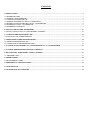
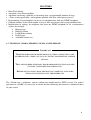
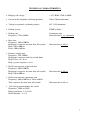
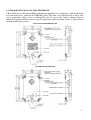
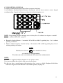
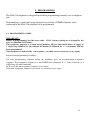
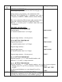
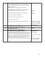
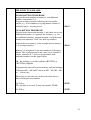
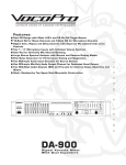
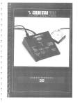
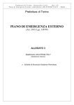
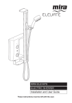
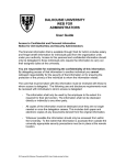
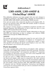
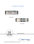
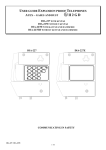
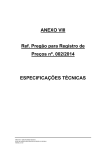
USER GUIDE AND INSTALLATION MANUAL
WEATHERPROOF « HANDS FREE » TELEPHONE
DIA-376
CONTENTS
1. PRESENTATION .......................................................................................................................................................................... 3
1.1 TELEPHONE TYPES ................................................................................................................................................................... 3
1.2 GENERAL CHARACTERISTICS ................................................................................................................................................ 4
1.3 CONTENTS OF THE PACKAGE ................................................................................................................................................. 5
1.4 GENERAL DESCRIPTION OF DIA-376 TELEPHONE .............................................................................................................. 5
1.5 TECHNICAL CHARACTERISTICS OF DIA-376 TELEPHONE................................................................................................ 6
1.6 DESCRIPTION OF DIA-376 TELEPHONE ................................................................................................................................. 8
1.7 DESCRIPTION OF KEYPAD ....................................................................................................................................................... 9
2. INSTALLATION OF THE TELEPHONES ............................................................................................................................. 10
2.1 INSTALLATION OF DIA-376 CABLE ENTRIES ASSEMBLY ............................................................................................... 10
3. LAYOUT OF THE TELEPHONE CARD ................................................................................................................................ 11
3.1 FUNCTIONS AND JUMPER SETTINGS .................................................................................................................................. 11
4. CONNECTION OF THE TELEPHONE SETS ........................................................................................................................ 12
4.1 OPENING THE TELEPHONE SET ............................................................................................................................................ 12
4.2 CONNECTION OF THE TELEPHONE LINE ............................................................................................................................ 12
5. USAGE OF SINGLE-BUTTON (S1) / MULTI-BUTTON (S2, S4, S8) TELEPHONE ......................................................... 13
6. USAGE OF THE TELEPHONE WITH FULL KEYPAD ....................................................................................................... 13
7. RELAY BOARD - DOOR ENTRY / PUBLIC ADDRESS....................................................................................................... 16
7.1 AMPLIFIER CARD ..................................................................................................................................................................... 17
8. PROGRAMMING ....................................................................................................................................................................... 18
8.1 PROGRAMMING CODES.......................................................................................................................................................... 18
9. OPERATIONAL COMMAND CODES .................................................................................................................................... 26
10. MAINTENANCE ....................................................................................................................................................................... 27
11. IN THE EVENT OF A PROBLEM ......................................................................................................................................... 27
WEATHERPROOF TELEPHONE DIA-376
AND VARIANTS
1. PRESENTATION
1.1 TELEPHONE TYPES
DIA-376
WITH KEYPAD
DIA-376S1
WITH 1 BUTTON
DIA-376S2
WITH 2 BUTTONS
DIA-376S4
WITH 4 BUTTONS
DIA-376S8
WITH 8 BUTTONS
3
1.2 GENERAL CHARACTERISTICS
EQUIPMENT FOR INDUSTRIAL SITES « HANDS FREE » WEATHERPROOF
TELEPHONES SERIES DIA-376
DEGREE OF PROTECTION
IP66 – DIA-376
NOTE
THIS PRODUCT CONFORMS TO IP66 (MODEL 376)
WEATHERPROOFING CLASSIFICATION
THE GUARANTEE IS VALID ONLY WHERE PRODUCTS ARE INSTALLED AND
OPERATED STRICTLY IN ACCORDANCE WITH THE INSTRUCTIONS DESCRIBED
IN THIS MANUAL.
NO GUARANTEE CAN BE INVOKED IF DETERIORATION RESULTS
FROM AN EXTERNAL SOURCE OR FROM LACK OF ADHERENCE
TO INSTRUCTIONS FOR USE.
IN THE DESIRE FOR CONSTANT IMPROVEMENT, THE INFORMATION
CONTAINED IN THIS DOCUMENT AND THE CHARACTERISTICS OF THE
EQUIPMENT MAY BE SUBJECT TO MODIFICATION WITHOUT PRIOR NOTICE
EUROPEAN STANDARDS
UNITS BEARING THE CODE “ CE ” CONFORM TO EMC DIRECTIVE EMC (89/336/EEC)
AND THE DIRECTIVE RELATING TO LOW VOLTAGE (73/23/EEC) FORMULATED BY
THE EUROPEAN COMMUNITY.
UK BABT APPROVAL
UK BABT APPROVAL NO S/4130/3/Y/504612
REN (RINGING EQUIVALENCE NUMBER) = 1
4
1.3 CONTENTS OF THE PACKAGE
The equipment you have received comprises :
•
•
•
•
a telephone set
a user manual
a set of labels
cable entries
1.4 GENERAL DESCRIPTION OF DIA-376 TELEPHONE
The « Hands free » weatherproof telephones are Central Battery (CB) or Automatic Central
Battery (ACB) telephones without handset which can be used in centrally powered networks or
installations within the voltage limits permitted by our equipment (see technical characteristics
para.1.5 below).
These telephones are equipped with:
•
•
•
•
•
•
•
•
•
A weatherproof loudspeaker
A weatherproof and vandal-resistant « Electret » type microphone
An electronic circuit card
An on-line LED
A keypad with function keys
1 button for S1 version
2 buttons for S2 version
4 buttons for S4 version
8 buttons for S8 version
5
FEATURES
•
•
•
•
•
•
•
Pulse/Tone dialing.
Automatic clear down capability.
Automatic answering capability or answering after a programmable number of rings.
« Tone security protection » (microphone operable only after called party answers)
Programming of stored numbers locally or via telephone line from any DTMF telephone.
Chained numbers if the called number is busy or does not answer after a programmable time.
Modification of settings via telephone line from any DTMF telephone or via a maintenance
station, for example:
Ringing type
Ringing volume
Loudspeaker volume
Dialing type
Automatic answer etc...
1.5 TECHNICAL CHARACTERISTICS OF DIA-376 TELEPHONE
IMPORTANT
THESE MICROPROCESSOR BASED PRODUCTS, WHEN CONNECTED TO THE
TELEPHONE LINE, CARRY OUT AN AUTO-TEST BY TRANSMITTING AUDIBLE
SIGNALS.
THEY ARE EQUIPPED WITH MANY PROGRAMMABLE FUNCTIONS AND ARE
FACTORY CONFIGURED FOR NORMAL USE.
BEFORE INSTALLATION, READ THIS MANUAL CAREFULLY TO BE SURE
THE FACTORY SETTING SUITS THE DESIRED USE.
The « Hands free » telephones operate without any modification to PSTN circuits. For perfect
operation on a PABX, it is necessary to ensure that the following characteristics conform to those
of your switch.
6
TECHNICAL CHARACTERISTICS
• Ringing call voltage
> 35 V RMS 25Hz or 50Hz
• Current in the telephone (off-hook position)
35mA (20mA minimum)
• Voltage at terminals (on-hook position)
48V (24V minimum)
• Dialing system
DTMF or Pulse
• Dialing tone
Frequency: 270 to 540Hz
Continuous tone
Detection time 2 sec. minimum
• Busy tone
Frequency: 300 to 500 Hz
Beep/pause sequence for more than 10 seconds.
Beep: 100 to 600 ms
Pause: 100 to 600 ms
Detection time 4-10 sec
• Distance ringing tone
Frequency: 350 - 500Hz
Beep/pause sequence until far-end off-hook
Beep: 0.2sec. to 1.6 sec.
Beep + pause sequence < 6 sec.
• End of conversation sequenced tone
Frequency: 300 to 500 Hz
Beep/pause sequence for more than 10 seconds.
Beep: 100 to 600 ms
• End of conversation continuous tone
Frequency: 300 to 500 Hz or 760 to 840 Hz
Tone sequence for more than 10 seconds
Detection time 4-10 sec
Detection time 6-10 sec.
• Call voltage transmitted by the switch
Frequency : 50Hz or 25Hz
Ringing duration : 1.5s ± 0.5s
Pause duration : 3s ± 2s
7
1.6 DESCRIPTION OF DIA-376 TYPE TELEPHONE
CB or ACB type weatherproof (IP66) wall mounted telephone set, comprising a light metal backcase and front cover, protected by EPIKOTE paint. The front cover which pivots at up to 180°
and is removable, closes on to a weatherproof seal via two screws acting as hinges and two
hollow hexagonal retention screws or special (optionally vandal-resistant) screws. A special key is
needed to undo these screws.
FULL KEYPAD TELEPHONE SET
1 BUTTON TELEPHONE SET
8
1.7 DESCRIPTION OF KEYPAD
15 button weatherproof keypad with on-line reassurance indicator.
A self-adhesive membrane placed between the buttons and the micro contacts assures keypad
weatherproofing. Legend and layout are identical for both telephone sets.
NOTE : Programming 10 direct memory access for keys 0 to 9 is allowed see chapter « autodial
numbers M0 to M9 » page 22.
• Remotely checked phones : 8 memories M1 to M8 available by pushing keys 1 to 8 without
pushing call button.
• Phones without remotely checked facility : 10 memories M0 to M9 by pushing keys 0 to 9
without pushing call button.
NOTE
THE RECALL BUTTON
HAS THREE FUNCTIONS
ACCORDING TO PROGRAMMING:
FLASHING OR ONE-TOUCH MEMORY M1 OR MUTING MICROPHONE
NOTE :
A label kit is supplied with the telephone set in a plastic sachet.
You can personalize these labels with a text of your choice.
For this you have a special paper with protective glass cover or a black dilophane black/white
label to be engraved. Each function is described separately on page 16.
9
2. INSTALLATION OF THE TELEPHONE
2.1 INSTALLATION OF DIA-376 CABLE ENTRIES ASSEMBLY
10
3. LAYOUT OF THE TELEPHONE CARD
3.1 FUNCTIONS AND JUMPER SETTINGS
FUNCTIONS
REF
SENSITIVITY OF THE HANDS FREE MICROPHONE
Sensitivity up to 1m
Sensitivity up to 30cm
ST1
RECEPTION LEVEL ADJUSTMENT
Minimum setting : quiet location
Maximum setting : noisy location
NOTE : normal setting is carried out in factory (see drawing)
JUMPERS
MIN
MAX
MIN
MAX
MIN
R33
MAX
11
4. CONNECTION OF THE TELEPHONE SET
4.1 OPENING THE TELEPHONE SET
To gain access to the circuit board, unfasten the 4 fixing screws in the front cover of the case
using Allen key No 5 for the DIA-376 weatherproof telephone set.
4.2 CONNECTION OF THE TELEPHONE LINE
The connection of the unit to the telephone line is carried out on printed circuit board with the
plug-in connector reference « BR1 ».
Connect the telephone line to the terminals L1 and L2 of the connector « BR1 ».
GROUNDING THE TELEPHONE SET
Electrical grounding is carried out either externally via the grounding screw (situated at the
bottom of the case) indicated by the sign ⊥ or internally on the terminal ⊥ situated on the « BR1 »
connector on the telephone card.
A gas discharge tube is located on the card, to discharge possible overloads to earth.
12
5. USAGE OF SINGLE-BUTTON (S1) / MULTI-BUTTON (S2, S4, S8)
TELEPHONE
OPERATION : Each button dials a pre-programmed telephone number (see chapter on
programming page 22)
HOW TO MAKE A CALL
1
PRESS THE CALL BUTTON (S1 VERSION)
OR DESIRED CALL-BUTTON (S2, S4, S8)
The red indicator shows
When the called party answers, speak in front of the telephone from a distance of
Approximately 20cm (8in).
At the end of conversation, to free the line :
2
PRESS THE CALL BUTTON 2 SEC.
OR ALLOW THE TELEPHONE TO CLEAR DOWN
AUTOMATICALLY
The red indicator ceases to show.
IMPORTANT : For the CB telephone version, keep the button pressed whilst communicating.
Release the button to free the line.
6. USAGE OF THE TELEPHONE WITH FULL KEYPAD
HOW TO MAKE A CALL
1
PRESS THE CALL BUTTON
The red indicator show.
2
KEY THE NUMBER
When the called party answers, speak in front of the telephone from a distance of
Approximately 20cm (8in).
At the end of conversation, to free the line
3
PRESS THE CALL BUTTON
OR ALLOW THE TELEPHONE TO CLEAR DOWN
AUTOMATICALLY
The red indicator ceases to show.
13
HOW TO ANSWER A CALL
When the telephone rings
1
PRESS THE CALL BUTTON
OR ALLOW THE TELEPHONE TO CLEAR DOWN
AUTOMATICALLY
The red indicator shows
When the called party answers, speak in front of the telephone from a distance of
Approximately 20cm (8in).
At the end of conversation, to free the line :
2
PRESS THE CALL BUTTON
OR ALLOW THE TELEPHONE TO CLEAR DOWN
AUTOMATICALLY
The red indicator ceases to show
LAST NUMBER REDIAL
1
PRESS THE CALL BUTTON
The red indicator shows
2
PRESS B
When the called party answers, speak in front of the telephone from a distance of
Approximately 20cm (8in).
At the end of conversation, to free the line :
3
PRESS THE CALL BUTTON
OR ALLOW THE TELEPHONE TO CLEAR DOWN
AUTOMATICALLY
The red indicator ceases to show.
14
FLASH RECALL
PRESS « R »
A programmed flash recall of 270ms takes place
Length of time of flash can be adjusted by programming
The R button has a three functions according to the programming : flashing or direct memory M1
or muting microphone.
If « Direct Memory » is selected, the R button is used in the same way as the Call Button on the
« S1 » Autodial version.
NOTE
LENGTH OF CONVERSATION IS LIMITED IN THE FACTORY TO A
LIMIT OF 4 MINUTES.
IT CAN BE CHANGED BY PROGRAMMING.
MUTING MICROPHONE
In noisy environment, it may be useful to activated or deactivate the microphone by pushing a
key.( « R » key is used )
For this facility, program the unit as following :
*24xx* = 0 Flashing time deactivated.
*32xx* = 99 going « on hook » by pressing a memory key a long time deactivated.
At the beginning of the communication, microphone is activated.
By pushing « R », microphone is still on.
By releasing « R », microphone is deactivated.
Microphone is then activated by « R » key as a « PTT » key (push to talk) till the end of the
communication.
15
7 RELAY BOARD – DOOR ENTRY / PUBLIC ADRESS
• This optional card connected via a flat ribbon cable to telephone card , enables the activation of
a relay from a remote telephone or system. This relay can activate for example:
• electric door entry mechanism
• lighting
• public address amplifier with loudspeaker
In its factory setting, the code to activate the relay is 1. This code must ALWAYS be keyed
between two * characters. Keying * 1 * from a remote telephone will therefore activate the relay.
Wherever a double relay card is used, the second relay is activated by code *2*, by adding 1 to the
first relay code value.
Keying this code on the keypad of a telephone equipped with a relay board will not activate its
own relay.
In the factory setting, the activation time of the relay is 2 sec. The DTMF code * is used to deactivate the relay. The activation code (up to 4 digits) and the time (value between 00 and 99
seconds) are modifiable (see programming).
NOTE
IF THE ACTIVATION TIME IS 00 THE TIMING IS NOT ACTIVATED.
TO DE-ACTIVATE THE RELAY SIMPLY PRESS *
IN ALL CASES THE RELAY WILL BE DE-ACTIVATED ON HANGING UP.
• Relay contact capacity: 60 Volts, 1 Amp
• ST1, ST2 setting jumper:
- T relay closed when activated
- R relay open when activated
ST2
1 relay board
- -
WK026CR
A
+
+
BR1
BR2
B
+
+
TEL
CDE2
RL2
U1
TEL
CDE1
RL1
A
- B
BR1
R
WK026CR
TEL
CDE1
RL1
A
1 T
R
U1
R
+
+
P1
G
T
ST1
- -
1
B
P1
G
T
ST1
2 relays board
16
7.1 AMPLIFIER CARD
All variants can be equipped with this booster card which amplifies reception by 10-20 dBA
subject to current available and the balance of the loudspeaker compared with the microphone.
Can be fed by the line or a 1.5VA external source.
Several applications are possible:
• 1/ Remotely fed by the telephone line and internal loudspeaker (minimum current 40mA).
Voice is amplified by approx. 10Dba.
• 2/ External 12VDC power supply and internal loudspeaker. Voice is amplified by approx. 20
Dba. If 12V power supply is removed, case 1 applies.
In case 1 and 2 jumpers ST1 and ST2 are in position 1 and ringing is not amplified.
• 3/ External 12 VDC power supply and external loudspeaker. Voice and ringer are then
amplified by approx. 20 Dba.
Jumper ST1 is in position 1 and ST2 IN POSITION 2. The external loudspeaker must be
connected to 1 and 2 on BR2.
If the 12VDC power supply disappears the telephone functions with its extension loudspeaker
amplified by the line current.
Potentiometer R5 facilitates volume adjustment in the 3 cases within the limit of distortion and
feedback. Connection of the external 12VDC voltage on +/-3 on terminal BR1.
17
8 PROGRAMMING
The DIA-376 telephone is designed to facilitate programming remotely over a telephone
line.
Programming is carried out using sequences keyed from a DTMF telephone, when
connected to the D|IA-376 telephone to be programmed.
8.1 PROGRAMMING CODES
IMPORTANT :
Before all programming, key the access code : *1234* (factory setting) or as changed by the
user (see function 12/13 below).
The acceptance sequence is a single beep if memory M0 (see function 18 below) is empty or
a single beep followed by the contents of Memory 0 followed by « * » if memory M0 has
been programmed.
Non-acceptance is indicated by « no-response » in which case it is necessary to try again.
Proceed with programming as follows :
For each programming sequence below the telephone gives an acceptance/non-acceptance
sequence. The acceptance sequence is a mix DTMF tones (functions N° 1, 5 and 18 below) or a
single beep (all other functions).
In all cases the non-acceptance sequence is two beeps.
If the non-acceptance sequence is received, it is necessary to try again.
18
Function
Function
No
AUTODIAL NUMBERS (If no chaining is required)
1
Programming code
If chaining is required, use function No5 instead (page 25)
During memory programming , the combination #11#
Represents the recognition of a continuous tone with a
frequency of 440 Hz ± 100Hz (standard) before dialing.
This is the standard for UK and many other countries but in
Some other countries #10# may be applicable instead,
Whereby a 2-second pause is inserted rather than tone
recognition.
PROCEED AS FOLLOWS :
SINGLE BUTTON TELEPHONE
Program button :
N = autodial number from 1 to 15 digits.
*5001*#11#N*
Program empty memory : (factory preset)
*5002**
DUAL-BUTTON TELEPHONE
Program lower button :
N = autodial number from 1 to 15 digits.
*5001*#11#N*
Program empty memory :
*5002**
Program upper button :
N= autodial number from 1 to 15 digits.
*5005*#11#N*
Program empty memory : (factory preset)
*5006**
For 4 - BUTTON TELEPHONE
program memories 1, 3, 5, 7 with autodial numbers and
memories 2, 4, 6 and 8 as empty memories.
2
For 8 – BUTTON TELEPHONE
Program memories 1 – 8 with autodial numbers and set
chaining times T1 and T2 (see function 5 below) to 00
seconds.
For full keypad telephone, to assign button R (recall) to
Memory 1
TYPE OF DIALLING / CONFIGURATION
Although this equipment can use either loop disc or DTMF
Signaling only the performance of the DTMF signaling is
For 8-button telephone
ONLY.
*2000* and *2100*
*2400*
subject to regulatory requirements for correct operation. It
is therefore strongly recommended that the equipment is set
up to use DTMF signaling for access to public or private
emergency services.
DTMF signaling also provides faster call set-up.
For configuration, each function has a value as follows:
1/ DTMF dialing and automatic clear down. 00
*1000*
2/ For pulse dialing and automatic clear down. 01
*1001*
3/ No access to memory dialing : 02
4/ No clear down on receipt of tone : 04
5/ Push to talk mode : 08
Those values should be summed and the total applies e.g. :
3
LOUDSPEAKER VOLUME
*1007* = pulse dialing,
no access to memory
dialing, no clear down
on receipt of tone.
*140V*
V= volume from 1 to 9 (factory setting = 5)
4
RINGING VOLUME
*160V*
V= volume from 1 to 7 (factory setting = 7)
5
PROGRAMME A NUMBER CHAIN
It is possible to program a number chain, so that, for
autodial buttons, if the first number dialed is busy or does
not answer, the telephone will dial one or more alternative
number in a ‘chain’ until successful connection is made.
All telephone numbers programmed into the chain must be
different, no number may appear more than once.
(see note in function 1 above for usage of #11# and #10#)
*500M*#11#N*
M (memory) =
1,2,….8 max.
N= Call number up to 15
digits
The chain stops at the
first empty memory.
20
THE STEPS TO TAKE ARE :
SINGLE-BUTTON TELEPHONE
Program the main number in memory 1 and additional
Numbers in memories 2-8.
Program an empty memory following the last number
entered, e.g., if two numbers are programmed, memory 3
should be empty : (factory preset)
*5003**
DUAL-BUTTON TELEPHONE
Program lower button with memory 1 and either one or two
Additional memories (as required) for chaining, e.g., for
two additional numbers, program memory 1 with the main
Number and memories 2 and 3 for back-up numbers.
Program the next memory, in the example shown memory
4, as an empty memory :
*5004**
Memory 5 is designated as the main number for the upper
Button. This is programmed in the same way as memory 1.
Finally, memories 6, 7 and 8 are programmed with
additional numbers for the upper button.
NB : No chaining is possible with the 4-BUTTON or
8-BUTTON telephone.
To program the interval between memory auto-dial attempts
T1 between M1 – M2 and T2 between M2 – M3, M3 – M4
etc… if necessary
These times are the intervals in the event of no-answer
Before dialing the next number.
For T1 key :
TT is the time in seconds. If only one number TT=00
*20TT*
For T2 key :
*21TT*
21
If chaining 2 or several numbers, 2 choices are possible :
a) to hear what actually happens on the line :
program T1/T2 with even number (e.g., :30 sec)
b) to mask what happens on the line (no-answer, busy
tone,…) until the called party picks up, by simulating
ringing and flashing LED. On detection of speech from
the called party, a long beep announces to both parties
that the communication has been established, the LED
shows constant. For this, program T1/T2 with an odd
number (e.g. 31 sec.)
6
NUMBER OF
ANSWER
RINGS
BEFORE
AUTOMATIC
In the factory, the telephone is set to answer automatically
after 3 rings. To change this number, key :
*11NN*
NN= 00 to 99
NN= 03 factory setting (answer automatically after 3 ring
or manually by pushing the button)
NN= 00 automatic answer with no ringing (suitable only for
programming)
NN= 99 No automatic answer (answer only manually by
pushing the button)
Important note :
Where 00 is programmed, both microphone and
loudspeaker are de-activated on auto-answer, where 0198 is programmed, the microphone is de-activated on
auto answer (but the loudspeaker is active). The
microphone can be activated by pushing any button. If,
in this case, the telephone receives programming signals
(from an operator or call-centre system, the loudspeaker
is de-activated. It can be re-activated by keying the code
* 9901 *
22
7
RELAY ACTIVATION TIME
This should be set to
*25DD*
There is no limit to the relay activation duration.
The relay is de-activated by pressing the * key or by
hanging up.
DD= 01 to 98
DD= 00 (no limit)
Factory setting 02 (sec.)
ACTIVATION CODE
In the factory, the relay activation is set to 1.
NOTE
The code can be between 1 to 9999
If this code has 4 digits, it must not be the same value as the
programming access code.
The remote command code is a 4 digit code. To program it,
2 actions are required :
Programming of thousands and hundreds, identified below
as T and H
Programming of tens and units, identified below as D
and U
For T and H, key :
*26TH*
TH = 00 to 99
If T = 0 it is a 3 digit code
If TH = 00 It is a 2 digit code
For D and U, key :
*27DU*
DU = 00 to 99
If THD = 000 It is a 1 digit code
8
MAXIMUM CALL DURATION
Length of conversation before automatic clear down
∗12XX∗
∗
Range XX=-00 No limit
XX=-99 99 minutes
Factory setting 4 minutes.
23
9
DURATION OF SILENCE BEFORE AUTOMATIC *13XX*
CLEARDOWN
XX = 30 seconds (factory setting)
XX = 00 Does not clear down on duration of silence
XX = 99 seconds
Note : frequency tones are taken as silence.
10
TYPE OF RINGING MODULATION
*15XX*
XX = 00 Pure Frequency (factory setting)
XX = 01 3 Frequencies mixed
11
DURATION FOR WHICH BUTTON MUST BE *17XX*
PRESSED
CONTINUOUSLY
BEFORE
TELEPHONE GOES « ON LINE »
XX = 00 Immediate (factory setting)
XX = 99 9.9 seconds
12
PASS CODE (1)
First two digits of programming pass-code
*30XX*
XX = 12 (factory setting)
XX = 10 (range)
XX = 99
13
PASS CODE (2)
Last two digit of programming pass-code
Note : The pass-code is a 4 digit code (from 1000 – 9999).
It is input in two halves, as described above.
*31XX*
XX = 34 (factory setting)
XX = 10 (range)
XX = 99
14
DURATION FOR WHICH BUTTON MUST BE *32XX*
PRESSED CONTINUOUSLY FOR CLEARDOWN
TO TAKE PLACE
XX = 20 (factory setting)
XX = 00 (range) no clear down
XX = 00 99 seconds
24
15
MINIMUM TONE RECOGNATION/CLEARDOWN *34XX*
FREQUENCY
XX = 25 250Hz (factory setting)
XX = 00 0Hz (range)
XX = 99 990Hz
16
MAXIMUM CLEARDOWN TONE FREQUENCY
*35XX*
XX = 50 500Hz (factory setting)
XX = 00 0Hz (range)
XX = 99 990Hz
17
RETURN TELEPHONE TO FACTORY SETTING
ERASE MEMORIES
*98XX*
XX=00 Acknowledgement from telephone after about 1.3s
XX = 02 Erase memories M0 – M9
18
PROGRAM TELEPHONE ID
*5000*N*
This is a code of up to four digits which should be
programmed into memory M0.
The telephone will automatically transmit this ID code
followed by « star » (*) on receipt of the command code
*0600* from a central system.
N = telephone ID up to 4 digits
25
9 OPERATIONAL COMMAND CODES
Function
Function
No
1
REQUEST TELEPHONE ID
Programming
code
*0600*
This code is transmitted by the central system to determine
the identity of a telephone calling the centre.
The telephone will respond with its telephone ID (see
programming code 18 above)
2
3
AUTOMATIC CLEARDOWN
At the end of a call without access to programming, the
central system or operator can effect an automatic clear
down by transmitting this code :
*0990*
However, if the call has included access to programming,
automatic clear-down is carried out by transmitting this
code :
*9900*
TEST MICROPHONE AND LOUDSPEAKER
*9700*
Acknowledgement from telephone : 1 sec. Transmission of
frequency of 1244Hz
Followed by : 1sec. Transmission of frequency of 622Hz
Note : After test, the loudspeaker is switched off.
To re-activate the loudspeaker :
*9901*
To conclude the test :
*9900*
26
10 MAINTENANCE
DIA-376 telephones require little maintenance to remain in excellent operational condition.
Carry out the following maintenance if necessary.
EXTERNALLY
Clean using a dampened soft cloth.
If you use a high pressure hose (preferably 50 bar) do so from a distance of about 1.50m (5ft)
from the telephone.
INTERNALLY
The telephone requires no internal maintenance. Do not insert any fluid into the telephone set.
WEATHERPROOFING
At least once a year and otherwise whenever closing after opening check thoroughly the effective
weatherproofing of the joints, seals and apertures and state of the silicon sealant and repair or
replace as appropriate (see Note – page 4).
11 IN THE EVENT OF A PROBLEM
Before consulting the maintenance service, we advise you to check the following points:
PROBLEM WITH LINE CONNECTION OR DIALLING
Check telephone line on the connection terminal.
Check the button is not jammed by foreign object.
TRANSMISSION PROBLEM
Check the setting of jumper ST1
If transmission if weak, check that the microphone holes are not blocked by a foreign object.
RECEPTION PROBLEM
If transmission if weak, adjust the reception to the level required.
Vennenweg 7 5807 EH Oostrum (L) The Netherlands
T:+31 (0)478 580 222 F:+31 (0)478 515 823 e-mail: [email protected]
27