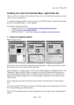
1
Ca3D-Engine
Making New Materials
Carsten Fuchs
June 24, 2005
Contents
Contents
1 Introduction
3
2 The Ca3DE Material Development Kit (MDK)
2.1 Windows and Linux specifics . . . . . . . . . . . . . . . . . . . . . . . . .
3
3
3 Before you begin
4
4 Textures and dynamic lighting
4.1 Introduction to new-style textures . . . . . . . . . . . . . . . . . . . . . .
4.2 The next fact about new-style textures . . . . . . . . . . . . . . . . . . . .
4.3 Acquiring textures . . . . . . . . . . . . . . . . . . . . . . . . . . . . . . .
4
4
6
6
5 Making new Worlds
6
6 Making new Sky Maps (Environment Maps)
6
7 Making new Textures (diffuse-, normal-, specular-maps,
7.1 Getting started . . . . . . . . . . . . . . . . . . . . .
7.2 Deriving normal-maps from bump-maps . . . . . . .
7.3 Obtaining normal-maps directly from 3D geometry .
7.4 Combining height-maps and normal-maps . . . . . .
7.5 The texture viewer . . . . . . . . . . . . . . . . . . .
...)
. . .
. . .
. . .
. . .
. . .
.
.
.
.
.
.
.
.
.
.
.
.
.
.
.
.
.
.
.
.
.
.
.
.
.
.
.
.
.
.
.
.
.
.
.
.
.
.
.
.
7
. 7
. 8
. 9
. 11
. 11
8 Making new Models
12
8.1 Dependencies among models . . . . . . . . . . . . . . . . . . . . . . . . . . 12
8.2 Models and dynamic shadows . . . . . . . . . . . . . . . . . . . . . . . . . 14
8.3 Models and dynamic lighting . . . . . . . . . . . . . . . . . . . . . . . . . 15
9 Compiling the DeathMatch source code
15
9.1 Compiling on Win32 . . . . . . . . . . . . . . . . . . . . . . . . . . . . . . 16
9.2 Compiling on Linux . . . . . . . . . . . . . . . . . . . . . . . . . . . . . . 17
10 Making new MODs
17
11 Other Contributions
18
12 Solving Problems
19
13 When you are finished
19
14 Legal
20
2
1 Introduction
1 Introduction
Dear Reader, if you are interested in making new materials like new textures, new
worlds, new models, new sky maps or even new MODs for the Ca3D-Engine – then this
document is for you. This document is intended as a guide and introduction to making
such new materials.
Please be aware that the Ca3D-Engine is a product that is under constant development. Therefore, making new materials is subject to changes as the underlying concepts,
structures, tools, implementations or philosophies change. For example, file and path
names change and their processing may vary across software versions, and not all of the
tools that are described in this text may be available for download yet. Consequently,
this text should only be considered as a very preliminary introduction that aims at
people who already have a basic understanding of computer technology and are safe on
solving smaller problems on their own.
I am releasing this document despite its preliminary nature because many people were
asking for it. With the development of the engine technology being very tedious and
time consuming, and due to a lack of artistic skills, I am focusing my own efforts on the
technology and the source code. Therefore, I would be very happy and grateful about
anybody who likes the Ca3D-Engine and would dedicate new materials to it!
2 The Ca3DE Material Development Kit (MDK)
To start, all you need is this text and the Material Development Kit Ca3DE-MDK.zip.
The file is available in the download area at the Ca3D-Engine website at http://www.
Ca3D-Engine.de. It is self-contained, meaning that the current demo release of the
Ca3D-Engine is not required.
In order to install the MDK, simply unzip the packed file that you downloaded from
the website. Please make sure that the directory structure is preserved.
Later, depending on what new materials you want to make for Ca3DE, supplementary
tool programs may be required that are not included with the MDK. They are available
from external websites, and you will usually find a link to their download location in the
corresponding text of the following sections.
2.1 Windows and Linux specifics
The instructions and examples in this manual were written with reference to the Microsoft Windows operating system. Now, with Ca3DE being also available on Linux,
I rely on the Linux users skills and experience to transfer the provided information to
their favourite OS. The transfer is almost always very easy to achieve: Examples include
that Linux has tar.gz file archives versus zip file archives on Windows, and that the
Linux executables are suffixed with linux versus exe on Windows.
I hope that this helps to keep this manual easy and intuitive to understand for everyone. The alternative has been to mention all specifics for each OS in each text fragment
and each example.
3
3 Before you begin
3 Before you begin
Before you go on to the next sections, please be aware that making certain types of new
materials is very MOD-specific. For example, before you make any new worlds or new
models, ask yourself which MOD you are going to make it for. I am sure that you knew
that already, but I felt it was worth mentioning it.
For other types of materials, the matter is simpler: New textures or new sky maps are
not quite so specific to a certain MOD, whereas modifying or writing new source code
..
is so very specific that I’m assuming you know what you’re doing. ^
Please note that many auxiliary programs that come with the Ca3DE-MDK are command line driven programs! That means that in general, you can not double-click on
them or use drag’n’drop. Rather, for using WcMap2Ca, CaBSP, CaPVS, CaLight, and other
programs, you have to open a command line window (“DOS prompt”), and work from
there. Detailed instructions on using these programs are given later in this document.
If you are completely new to Ca3DE, a good way to familiarize yourself with the
Ca3D-Engine is to study the user manual that is included both with the MDK and the
Ca3DE demo releases. It will also help you understand this document better. Then,
it is best to start small. Start with small samples, until you are familiar with all the
tools and know how everything works. For problem solving and contacting me per email,
please refer to section 12.
4 Textures and dynamic lighting
This section will briefly introduce you to dynamic lighting and the consequences arising
out of dynamic lighting to textures.
Please read this section entirely, even if you are not primarily interested in textures.
Many important key concepts are covered herein that are also fundamental to other aspects of Ca3DE and require a basic understanding.
4.1 Introduction to new-style textures
Some time ago, when earlier releases of Ca3DE were current, you were probably familiar
with other 3D engines like Quake 3 and Half-Life 1, which in turn also helped you to
become familiar and deal with Ca3DE, at least conceptually. However, Ca3DE evolved,
and the latest releases come with dynamic, per-pixel lighting and shadowing. The first
release of Ca3DE with these state-of-the-art features was in October 2003, even before
Half-Life 2 and Doom 3 came out.
Therefore, I’d like to take the opportunity and introduce you briefly into the new
aspects of dynamic lighting. Actually, this section is not so much about dynamic lighting,
but rather about the “new” textures that form the basis of the new lighting technology.
First, lets review the “old-style” textures, as they were common with graphics engines
of the Quake3 and Half-Life 1 era: These textures consisted of a single image. They have
usually shown some material surface, and normally also contained some fixed, “built-in”
lighting, almost like a photograph does.
4
4 Textures and dynamic lighting
New-style textures for Ca3DE dynamic lighting are different: Now, each texture consists of up to five individual images, providing an augmented description of the surfaces
material: A diffuse-map, a height-map, a normal-map, a specular-map, and a luminancemap.
The Ca3D-Engine mathematically combines these individual images later (also taking
interactions with the dynamic light sources into account) in order to render a properly
illuminated surface material: A diffuse-map defines the material color of a surface when
it is diffusely lit, almost like an “old-style” texture image did. However, it really contains
only the material texture, nothing else. For example, a diffuse-map of a corrugated metal
or a rough rock surface could be an image that only has a single shade of grey! heightmaps (also called bump-maps) store the height of the surface as a gray-scale image: dark
is low and white is high. They often only serve as an intermediate product for creating
normal-maps. The normal-map contains encoded information about the shape of the
surface. Artists often derive a normal-map from a height-map, or create it directly from
a 3D model. You can normally recognize a normal-map immediately by its typically
bluish appearance. specular-maps define how much a materials surface mirrors light,
and luminance-maps define the light that they emit (e.g. a computer screen or a panel
with LEDs). Section 7 about making such new textures has more in-depth information
about these indiviual maps.
If you have never seen all these maps before, I encourage you to have a look into the
Ca3D-Engine/Games/DeathMatch/Textures directory, which contains many very good
examples. (Note that quite often, not all four maps of a texture are present. They don’t
have to, because many materials do not have specular reflections or don’t actively emit
light. Only the diffuse-maps are mandatory. Omitting the normal-maps is possible, but
not sensible, because normal-maps are very important for the cool effects associated with
dynamic lighting.)
For now, the important message is that “old-style” textures should not be used any
longer with Ca3DE. Technically, they still work properly, but they will look very bad
compared to the new-style textures.
5
5 Making new Worlds
4.2 The next fact about new-style textures
New-style textures are now organized in and closely related to the new Ca3DE Material
System. Please refer also to the Material Systems documentation for details about
creating new materials from new-style textures.
4.3 Acquiring textures
Especially when you want to make new worlds, there is the problem to acquire a set of
textures that you can use for the new world:
Internet resources: As they are so new, only a very small amount of high-quality newstyle textures is available on the internet. Those that are available are usually
copyright protected, low-quality, or unusable for other reasons. Old textures libraries like “The WadFather” drop out anyway, because they only carry old-style
textures. If you are more lucky than I am, and actually find a collection of textures
that can be used with Ca3DE, please make absolutely sure that you do not infringe
on copyrights and ask the author for permission.
Ca3DE resources: For the purpose of making new worlds for Ca3DE, you may of course
use the textures that come with Ca3DE. These textures were made by highly
talented people exclusively for Ca3DE. They are included with the Ca3DE MDK,
and using them is the fastest way to make a world with high-quality textures.
Making textures yourself: Ideally, you’d create your own set of new multi-image textures. No matter if you then use them for your own worlds and/or offer them to
other artists, this is really the best solution! Please refer to section 7 for more
details on making your own textures.
5 Making new Worlds
Great news: the Ca3DE World Editor CaWE is now available, and has its own user
guide! Both CaWE and its documentation are still under construction, but already
available and useful. Please pick up the latest issue of the CaWE User’s Guide at the
Ca3DE website http://www.Ca3D-Engine.de (→ Downloads → Documentation).
6 Making new Sky Maps (Environment Maps)
The good news is that Peter Kleiner, the author of the famous, high-quality sky maps of
Serious Sam 2, has also created some new, exclusive, and excellent sky maps for Ca3DE!
You can see them in the worlds that come with the Ca3DE demo and MDK. Thus, sky
maps are the only artistic resource from which Ca3DE does not suffer shortage, and
there is currently no real need for making more sky maps for Ca3DE (unless you are
.. ).
absolutely positive that you can do better than Peter ^
6
7 Making new Textures (diffuse-, normal-, specular-maps, . . . )
There are several tools which new sky maps can be created with, one of them is TerraGen, available at http://www.planetside.co.uk. Also have a look at Peter Kleiners
website at http://www.terradreams.de.
Sky maps for Ca3DE must be stored in the SkyDomes subdirectory, and the six individual files must be properly suffixed: If “MySky” is the name of your sky map, the
files in the SkyDomes subdirectory must have the names MySky bk.bmp, MySky dn.bmp,
MySky ft.bmp, MySky lf.bmp, MySky rt.bmp, and MySky up.bmp, respectively. Note the
separating underscore “ ” in the names.
The files must be stored in the Windows bmp bitmap file format, using a color depth
of 24 BPP. The dimensions of all files must be 256 ∗ 256, 512 ∗ 512, or 1024 ∗ 1024 pixels.
7 Making new Textures (diffuse-, normal-, specular-maps, . . . )
Self-making new textures requires mostly computer graphics and artistic skills, and it’s
attractive at least for two reasons:
• There are still only very few high-quality new-style textures in existence. It would
be great if you helped out with that. Simultaneously, it is a big opportunity to
achieve something unique.
• In order to produce high-quality results, dynamic lighting requires that the texture
and level artist work much closer together than ever before! Making new textures
for your own levels yields the maximum possible coordination and best results.
After the short introduction to new-style textures in chapter 4, where you learned that
such new textures actually consist of a combination of multiple images (called maps), we
will now talk in greater detail about the multi-image components (maps) of new-style
textures and about methods to create such maps.
Initially, we will restrict ourselves to making new-style textures for world polygons,
that is, those textures that you apply in CaWE to the surfaces of the brushes. Making
appropriate new-style textures for models is an entirely different matter that I’d like to
defer until later.
7.1 Getting started
In almost all cases, you start making a new texture with the diffusemap. Diffuse-maps are still almost always created manually in an image
processing program, e.g. hand-painted or derived from a photograph,
similar to the way old-style textures were made in the past.
The diffuse-map shows the material color when the surface is diffusely
lit. Thus, you should not draw any hard shadows into the diffuse map
– they are automatically generated by the engine later. You should
however, in some cases, draw some soft shadows into the diffuse-map,
sort of a “reachability factor” (“How hard is it for the light to reach a
certain spot on the texture?”). This implies that a diffuse-map of, for
7
7 Making new Textures (diffuse-, normal-, specular-maps, . . . )
example, a corrugated metal or a rough rock surface could be an image that only has a
single shade of grey!
Also not that the end lit material tends to look best when you use pixel values of
medium brightness. Moreover, high-contrast and high-frequency components should be
used with care in diffuse-maps, as such components often interfere with the normal-maps
later, compromizing the effect of dynamic lighting. Also the specular highlights might
look strange with such diffuse-maps.
Specular-maps (sometimes also called gloss-maps) define the shininess
of the material. They are conveniently created together with or derived
from their diffuse-map. Bright values mean that the material is very
shiny, dark values mean that the material is mat. Note that specularmaps are not limited to gray-scale images: Their tone (color) modulates
with the color of the light source.
Specular-Maps often have the strongest impact on dynamic lighting.
Note that for many materials that only have diffuse light reflection
characteristics (e.g. sandstone), specular-maps can often be omitted
entirely.
Luminance-maps define the light that a texture emits. As with
specular-maps, they are easiest created together with their diffuse-map,
and often very simple in nature. The light of luminance-maps is local
to the texture, and does not cast on any other surfaces or objects.
Typical occurances for luminance-maps are with LED panels or computer screens, but frequently they are not present at all, because most
materials do not actively emit light themselves.
7.2 Deriving normal-maps from bump-maps
Height-maps (also called bump-maps) are gray-scale images that define the height of the surface: dark is low and white is high. They often
only serve as an intermediate product for creating normal-maps. In
fact, Ca3DE converts all height-maps to normal-maps internally before
use. Some people convert the diffuse-maps to gray-scale images in order to obtain height-maps, but this does almost yield very bad quality.
It’s just a lazy trick that you should never use. Instead, you should
rather draw the height-maps properly. This is almost always very difficult though, and works best with either natural or organic materials,
or with high-frequency components like scratches, dents, and so on.
Another method is to obtain height-maps from the depth buffer information of some
rendered geometry. In this case, however, I’d recommend to skip height-maps entirely,
and render normal-maps directly from geometry as described in the next section.
8
7 Making new Textures (diffuse-, normal-, specular-maps, . . . )
Normal-maps are the most important component in dynamic lighting. They contain information about the shape of the surface. They
are normally never hand-made, but rather derived (using a software
tool) from height-maps. Please note that, according to practical experiences, combining diffuse-maps and normal-maps that both have highfrequency components (and the diffuse-map possibly high-constrast colors) tends to compromize the effects of dynamic lighting.
7.3 Obtaining normal-maps directly from 3D geometry
While the above “generic” method works well in many cases, it is often cumbersome to
create really good normal-maps manually (that is, by hand-painted bump-maps that are
then converted to normal-maps). This is especially true for textures with architectural or
technical contents, where precise and clean normal-maps of highest quality are desired.
Therefore, this section will introduce you to computing normal-maps directly from
3D geometry. We will restrict ourselves to textures for world polygons for now, but the
same technique extends to computing normal-maps for entire models later. Here is an
overview of the essential steps that are required:
1. You use your favourite 3D modelling software to create a spatial object whose
geometry represents the desired shape of the surface.
2. Save or export the 3D surface object to a file on disk. For some software, this may
require an exporter plug-in.
3. Import the file into another tool program that can compute the normal-map from
the input geometry.
4. Use the tool program to obtain the desired normal-map.
Some 3D modelling software is able to do steps 2 to 4 in one, e.g. XSI, which comes
with integrated support for these steps. Lightwave and Cinema 4D can also do these
steps in one, but require free plug-ins: The plug-in for Lightwave is availble at http:
//www.???, and the plug-in for Cinema 4D is available at http://www.???. Maya and
others probably work similar, but I’m not familiar with the details. 3D Studio Max can
also collapse steps 2 to 4 into one, but the required plug-in is commercially distributed
(non-free).
An alternative is to combine 3D Studio Max for steps 1 and 2 with ORB for steps
3 and 4. ORB can import many common file formats (also from other 3D modelling
programs), but is pretty slow.
Another alternative for 3DS Max is to use 3DS Max for step 1, the free exporter
plug-in from http://www.??? for step 2, and the ATI tool from http://www.ati.com/
developer/tools.html for steps 3 and 4. The ATI tool is faster, more powerful and
more advanced than ORB, but only supports its own native file format, which in turn
requires the additional exporter plug-in for step 2.
9
7 Making new Textures (diffuse-, normal-, specular-maps, . . . )
More detailed information (using 3D Studio Max)
While this manual cannot teach you how to use 3D Studio Max or any of the other 3D
modelling programs, this section will contain additional information to the steps outlined
above, in order to get you on the right track.
First, normal-maps are always the result of a projection: A low-polygonal model serves
as ray source. Rays are then cast along the normal vectors of the low-polygonal model.
The intersection of those rays with the high-polygon model then yields the normal vectors
at the intersection point, which are then taken as result values for the normal-map on the
starting polygon. See figure [DOES NOT YET EXIST] for an illustration. This principle
applies to both world polygons as well as more complex (e.g. character) models.
That means that in step 1, you do not only create a 3D surface object (high-poly
model), but also a very simple low-poly surface that only consist of a single rectangle
(two triangles). Note that both the high- and low-poly model should have the same
cross-sectional size, and that their size should fit the size of the desired final normalmap.
As a result, the work-flow is as follows:
1. Start with creating a rectangle that fits the size of the desired normal-map. This
will become the high-polygonal model.
2. Add as much detail as desired.
3. Export the result to disk.
4. Create another rectangle of the exactly same lateral dimensions, but offset to the
first such that the normal vectors of this rectangle can “see” the other model. As
this rectangle will become the low-polygonal model, it must be planar and no more
than two triangles are required.
5. Export this one to disk, too.
6. Now import both the low- and high-polygonal models into the ATI tool, set the
desired size, make sure that you have smooth-groups turned on (see below for an
explanation), and for objects with holes (like grates, ladders, . . . ) it is recommended to turn the “expand border” option off.
7. Render the normal-map.
8. Finally you need an image processing program in order to invert the green color
channel, because the ATI tool saves the normal-map vectors with flipped ycomponents. Inverting the green color channel (that is, replacing g by 1 − g)
fixes the problem.
9. You may scale down the resulting normal-map in order to obtain some smoothing
from the filtering, but keep in mind that this might also require a subsequent
renormalization of the normal-map.
Turning smoothgroups on is especially important for objects that are more complex than
a simple wall rectangle, e.g. character models. As demonstrated in the images to the
right, tracing normal vectors without smoothgroups enabled may lead to considering
regions on the high-polygonal model twice (overlaps) or not at all (breaks), whereas
with smoothgroups enabled, there is a smooth transition across the entire high-polygonal
model. The documentation of the ATI tool has more in-depth information in this regard.
10
7 Making new Textures (diffuse-, normal-, specular-maps, . . . )
Finally, here is a trick that applies to rectangular low-polygonal models as in our
texture example above, but not really to more complex models: As the normal vectors
of the low-poly, planar, rectangular surface always are parallel to each other and actually
point orthogonally away from the surface (even with smoothgroups turned on, as there
are no (non-planar) neighbouring triangles), the normal-map computation reduces to a
parallel projection. That means that you may, for example, create a sphere in front of the
high-poly surface, and the result will look as if you had modelled the sphere right into
the surface when it was actually only in front of it. In this case, the result will look like
a rivet. When you instead cut the front half of the sphere away, and reverse the normal
vectors of the remaining hemi-sphere (such that you can see the inside), the resulting
normal-map will look as if it had a spherical dent. This way you may create high-poly
surfaces that are not made from a single piece, but rather from a composition of several
pieces. This much simplifies the modelling process in many cases, especially for people
who are not safe with advanced modelling techniques. It also recudes the rendering time
in the normal-map tool, as fewer polygons are required to model a complex surface.
7.4 Combining height-maps and normal-maps
For surfaces with natural or organic textures (“smooth” height-maps), surfaces with
high-frequency height-map components (e.g. bumps, dents, scratches, . . . ), or surfaces
whose height-map is derived from the diffuse-map (that is, the height is actually materialdependent), it is usually best to derive the normal-maps simply from the height-map, as
described in section 7.2.
For technical or architectural surfaces however, the 3D method of section 7.3 is much
preferable. This 3D geometry method however can typically not handle (easily) the
properties of the previously mentioned surfaces.
Thus, for making a really good normal-map that has properties of both methods (e.g.
a tech wall with scratches), practical tests have revealed that no attempt should be made
to choose one from both methods for everything. Instead, simply create two maps: First
create a normal-map that contains the technical aspects of the surface, using the 3D
method of section 7.3. Then, additionally create an independent hand-drawn heightmap that contains the bumps, scratches, HF-components, and whatever you like.
Now comes the crucial point: The normal-map and the height-map will dynamically
combined by the (upcoming) Ca3DE Material System, which essentially adds both maps
in order to obtain the final result. Please refer to section [DOES NOT YET EXIST]
about the Ca3DE Material System for more details on combining a normal-map and
height-map in this way in a material shader.
7.5 The texture viewer
Together with the Ca3DE-MDK, I’m providing you with a texture viewer in order to
help and facilitate the development of new textures. The texture viewer lets you preview
a texture (that is, the combination of the diffuse-map, normal-map, specular-map, and
luminance-map) as it will appear in the engine.
11
8 Making new Models
The program file TextureViewer.exe is a command line driven program. Please run
it from the command line without any parameters in order to see a message about its
usage.
8 Making new Models
For model making, it is important to first decide which MOD you want to make models
for. This is specially true for animated models (like player models), because they are
usually MOD-specific and can not be shared among different MODs. Static models are
much easier to replace and to reuse.
Besides professional tools like 3D Studio MAX or LightWave 3D, which are very
expensive, there also exists the well-known tool Milk-Shape 3D.
Although MilkShape 3D has no built-in support for Ca3DE yet, I recommend it
warmly to you anyway: In the MilkShape dialogs, just choose to save or export your
models in the Half-Life mdl file format. Ca3DE is provided with an importer for models
in this file format. In conclusion, there is no problem at all with using MilkShape 3D to
make models for Ca3DE.
MilkShape 3D is available at http://www.swissquake.ch/chumbalum-soft.
8.1 Dependencies among models
Although it might not be obvious at a first glance, there are several dependencies among
certain models. It is worthwhile to have knowledge about these issues before you start
making own models, because it helps with resource planning and prevents expensive
problems later. I’ll describe several typical kinds of dependencies, considering the example of the Ca3DE DeathMatch MOD:
In the Ca3DE DeathMatch MOD, mutual dependencies affect the human player models and their weapons. First, lets deal with all models that are neither of both: Usually,
these other models are not closely related to each other, each of them has a separate
piece of game code associated that handles it, and thus they do not suffer from any
inherent dependency problems.
Human player models
Human player models are special, because they are usually intended to be 100% equivalent to each other. That is, if somebody makes a new human player model and offers
it for download, you expect it to work exactly like the ones that you already know. In
order to achieve this kind of equivalency, two assumptions must hold: The skeleton of
the new models must basically match the skeleton of the old models, and the animation
sequence numbers must refer to reasonably identical animations.
The animation sequences must match, because the engine has built-in knowledge that,
for example, sequence number 3 refers to an “idle (waiting)” animation, and that sequence number 27 refers to an “aiming with a shotgun” animation. It is entirely up to
you to animate your model to look at his wrist watch while aiming with the shotgun,
12
8 Making new Models
or to pick his nose, but it is important that sequence number 27 corresponds to some
“aiming with a shotgun” animation – because the same is true for all other models, and
the engine relies on it.
The skeletons must also match, for similar reasons: At least the basic hierarchical
structure (starting from the pelvis to the most important bones) must be identical, as
well as the names(!) of the corresponding bones. However, you are free to add bones
to the skeleton as you like, change their sizes or lengths, change their positions relative
to each other, and do many other interesting things. You may even omit bones if you
want to create a one-armed, one-legged hero. What works and what works not is easiest
determined by trying it out, but please do also refer to the next part about weapons:
Weapons
Weapons do usually come as a set of three models: “world” models, “player” models,
and “view” models.
“World” models are the models that lie around in the world, before someone picked
them up. They are usually not animated (or do only have a single animation sequence),
are independent from anything else, and are therefore in the same category as the “all
others” models, so that we need not be further concerned about them.
“Player” models are the weapons that you see in the hands of other players who
have picked up and are using that weapon. For the following discussion, I’ll refer to
the “player” weapon model as the “ p model”, and to the character model of a human
player as the “body model”.
First, if you consider the skeleton of a p model in a model viewer, you will find that
it resembles a partial body model (the bones from the pelvis to the shooting arm are
there!), before it diverges into additional bones for the actual weapon. Here is the crucial
point: In order for the engine to compute the proper position of the p model relative
to the body model, it (partially) has to match the skeletons of both models! That is,
it first computes the skeleton of the body model (depending on its current animation
sequence and frame). Then it considers the skeleton of the p model, starting at it’s
root, and tries to match it bone-by-bone to the previously computed body skeleton. If a
match was determined, the engine simply takes the information from the body models
bone also for the p model bone. Only when the matching breaks for the first time, the
engine resumes normal bone computing also for the p model. (This way you can for
example have a face-hugger (held by another player!) that is wagging it’s tail.) Matches
are made by comparing the names of the concerned bones, by the way.
As a consequence, if you want to make additional body models for the DeathMatch
MOD, and additional weapons, and you want to be able to combine each body model
with each weapon, then you’re forced to make sure that they all have a corresponding
skeletal structure and bone names!
“View” models are the models that you see in 1st persons view after you have picked
up a weapon yourself. They are also independent from anything else, but the engine
has usually special code for handling them. Thus, you can well make a replacement
weapon for e.g. the shotgun (matching the animation sequences of the existing “view”
13
8 Making new Models
weapon model, according to similar rules as indicated for making replacement human
player models), but you cannot introduce entirely new weapon models without writing
additional code for them.
Applicability to your own MOD
If you create an own MOD, things may or may not be different, of course. However,
please keep in mind that if you want to achieve a high degree of flexibility and ease of
maintenance, you’ll sooner or later probably experience the same rules and dependencies
as described here. They are the - relatively cheap - price for the ability to combine every
human player model with every weapon model.
8.2 Models and dynamic shadows
In order for your models to cast correct shadows using the stencil-buffer technique that
the Ca3D-Engine employs, it is required that all your models are “closed” (2-manifolds),
so that every edge connects exactly two triangles and there are no T-junctions. Also, the
winding order must be consistent – objects like Möbius strips are not allowed. There is
one exception to these rules: The Ca3D-Engine can also handle border edges that only
have exactly one triangle associated with them. However such edges do probably not
occur very often.
While all this is much simpler than it sounds (just make
some neat closed geometry, and stop reading here), there
is the case that I’d like to point out that will never work:
Edges that connect more than two triangles, or edges that
connect triangles with inconsistent winding.
Both cases may occur for example with simple
handrails, where the horizontal top bar meets the two vertical posts at the left and right end of the top bar. For
now, lets concentrate on the top and left bar, where each
bar is a simple rectangular box with a square cross section
as shown in the first image to the right (wherein the right post has been omitted).
When these two bars are joined like in the second image,
we have constructed the very case(s) that won’t work: The
highlighted edge connects four surfaces (two from each
bar), which makes the computation of correct shadows
impossible. (Note that the triangle subdivision of the rectangular surfaces is not shown in the images.) Moreover,
some of the adjacent surfaces have inconsistent windings,
implying additional problems. Even if you omit the top
surface from the vertical bar (this surfaces is indicated by
a different material in the first image), the edge still connects three faces (still some with inconsistent windings), which will still cause highly
incorrect shadows.
14
9 Compiling the DeathMatch source code
Solutions: The easiest is to move the vertical post elsewhere, so that the edges do not connect more than two
triangles any longer, e.g. as shown in the image to the
right. Even better (at least from a technical point-of-view)
is to make a proper mesh, that is, to model the L-shape as
one “water-tight” piece: The top face of the vertical bar
would be omitted, and the bottom face of the horizontal
bar properly connected to the inner (rightmost) face of
the vertical post. Of course, in more complex modelling
situations you may also use other techniques to solve similar problems.
8.3 Models and dynamic lighting
Ca3DE supports dynamic lighting for models as it does for the worlds. Currently, however, there is the problem that the only file format that Ca3DE can import (Half-Life 1
mdl file format) does not inherently support dynamic lighting.
A real solution to this problem will become available when other newer file formats
become more common, natively supporting dynamic lighting, and are suitable for replacing the existing file format. Another solution to this problem will be offered by the
upcoming Ca3DE material system. Until then, we’ll have to live with a work-around,
which I’ll describe in the rest of this section.
The work-around is basically very simple: Keep your modeling habits you have for
making “old” mdl files. The key idea is to store the new multi-image textures as separate
files, outside of the mdl file. That is, when you create your model e.g. in 3D Studio Max,
deal with the model geometry, the animations, and the diffuse-maps as you did before.
The result is a proper mdl file that contains the diffuse-map as texture. Now, export the
normal-maps and specular-maps from 3D Studio Max into separate files. The engine
will later collect the model and all separate image files, and combine them accordingly.
I’m aware that this is only a vague description. Please don’t hesitate to contact me
if you have any questions on this regard. While the current work-around works very
well for models that only have a single diffuse texture (and thus only require a single
normal-map and specular-map), I’ll soon clarify these issues also for models with more
than one diffuse texture.
9 Compiling the DeathMatch source code
This section exists to introduce you to compiling the Ca3DE DeathMatch source code
and to prepare you a little for the next section. Anyway, if you want to play around
with the source code, this is a good place to start.
The most important message here is to get and use the right compiler: Use Microsoft
Visual C++ 6.0 for compiling the Ca3DE MOD source code under Windows, and g++
3.3.x under Linux. The reason is that different compilers have different internal representations of C++ objects. Pointers and references to such objects are used as parameters
15
9 Compiling the DeathMatch source code
in function calls to and from the engine. For the demo and developer kit, I chose to
compile the Ca3D-Engine with the above mentioned compilers, and thus the MOD DLLs
must be compiled with the same compilers, too.
If you want to modify or enhance the existing DeathMatch source code, and also want
me to include your changes with my future public releases, please contact me before you
begin. Maybe I or others are already working on the same piece of code, and I prefer to
..
avoid double work. ^
9.1 Compiling on Win32
Before compiling, you have to set the Ca3DE environment variable to the directory that
contains the Ca3D-Engine directory. For example, on my computer I type
set Ca3DE=D:\Dev\Projects
but on your computer you’ll probably have to type something like
set Ca3DE=C:\Ca3DE-MDK
For convenience, you can also put this command into your autoexec.bat file or put
it into the system settings so that you don’t have to type it for each session over and
over again. The purpose of this environment variable is to let the Makefiles know where
all the interesting stuff that is required for compilation is located. Besides the proper
installation of the compiler, these are all assumptions that must be met for a proper
compile.
Next, cd into %Ca3DE%\Ca3D-Engine\Games\DeathMatch\Code, like
d:
cd %Ca3DE%\Ca3D-Engine\Games\DeathMatch\Code
If your directories are located on the C: drive, you’ll have to type c: instead of d:, of
course.
Now you have essentially three compile options. The commands
nmake /nologo /f Makefile.vc60 clean
nmake /nologo /f Makefile.vc60 clean version=release
delete all object files, libraries and executables both for debug and release builds.
nmake /nologo /f Makefile.vc60
compiles the DeathMatch DLL with development compile and link switches. Debug
information is included with the object files and executables.
nmake /nologo /f Makefile.vc60 version=release
compiles the DeathMatch DLL with release compile and link switches. This can take
much longer than with development switches, but the executables get a lot faster and
smaller.
16
10 Making new MODs
9.2 Compiling on Linux
Before compiling, you have to set the Ca3DE environment variable to the directory that
contains the Ca3D-Engine directory. For example, on my computer I type
export Ca3DE=/mnt/WinD/Projects
but on your computer you’ll probably have to type something like
export Ca3DE=∼/Ca3D-MDK
or
setenv Ca3DE ∼/Ca3D-MDK
For convenience, you can also put this command into your .bashrc file so that you don’t
have to type it for each session over and over again. The purpose of this environment
variable is to let the Makefiles know where all the interesting stuff that is required for
compilation is located. Besides the proper installation of the compiler, these are all
assumptions that must be met for a proper compile.
Next, cd into $Ca3DE/Ca3D-Engine/Games/DeathMatch/Code, like
cd $Ca3DE/Ca3D-Engine/Games/DeathMatch/Code
Now you have essentially three compile options. The commands
make -f Makefile.g++ clean
make -f Makefile.g++ clean version=release
delete all object files, libraries and executables both for debug and release builds.
make -f Makefile.g++
compiles the DeathMatch DLL with development compile and link switches. Debug
information is included with the object files and executables.
make -f Makefile.g++ version=release
compiles the DeathMatch DLL with release compile and link switches. This can take
much longer than with development switches, but the executables get a lot faster and
smaller.
10 Making new MODs
One of the most interesting and the most challenging tasks you can do with the Ca3DEngine is making an entirely new MOD for it. Here is an overview about how this
works:
17
11 Other Contributions
• “Design” your MOD. This is similar to creating the story-line and screen-play
of a movie. Ideally, you should have a precise idea about everything, or nearly
everything; details of your future MOD. For example, which weapons and which
monsters will appear in your MOD and how they will behave, in which setting
they play and of course the “goal” of the game.
The design is important because it allows you to plan the stages of the actual
work, and prevents you from the huge amount of work that can accumulate on late
changes.
• Create a directory sub-structure for your MOD in the Games directory. Look
carefully into the DeathMatch directory for an example. Although only the
Games/MyMOD/Code and Games/MyMOD/Worlds directories are mandatory, I recommend to lay out the other directories similar as well.
• Create an fgd file, with which you will configure the world editor CaWE later.
fgd files are simple text files. Please have a look into the DeathMatch.fgd for an
example. You can create your own fgd file by copying and modifying the example.
Note that the example file has a section that should be copied without modification,
and another section that you should overwrite with your MOD-specific data (see
the comments in the DeathMatch.fgd example).
• Acquire the textures that you want to use in your MOD, and create a material
scripts for them, as described in the Ca3DE Material System documentation.
• Configure CaWE with the fgd file by creating a new game configuration, and
make your first map. Keep it small and simple, you can add additional and more
sophisticated worlds later.
• Now you can compile the world as described in section 5, but it will not be possible
to run it, because there is no code and no DLL (dynamic link library) yet that
defines how the world is run.
• If you haven’t already, get the OpenWatcom C/C++ 1.2 compiler at http://www.
OpenWatcom.org. Also study section 9 for some additional information.
• Write code for your own MOD. Start with copying the DeathMatch source code.
Throw out what you don’t need, and modify what can be kept. This is the most
important and the most difficult part of all, but the DeathMatch MOD source code
should provide good examples for everything.
11 Other Contributions
If you want to contribute to Ca3DE in ways that are not mentioned in this text, please
do not hesitate to contact me.
For example, if you are a native English speaker, I would be happy if you proof-read
the Ca3DE related documents, like, for example, the user manual, the website, or this
18
12 Solving Problems
text. If you find something unclear and have a suggestion how it can be better explained,
you can even write corrected or additional sections if you want to.
If you want to operate a Ca3DE dedicated server – great! Currently there is not much
comfort about this; it still has to be done via the old-fashioned way (you must explicitly
publish the IP address and port of the server on a separate website). Thus, if Ca3DE
becomes more popular in the future, it will become crucial to develop and provide good
network backend services. I like the built-in server list in Half-Life pretty well, but I’d
also be willing to think about involving other programs like GameSpy. There is also
a nice article by Yahn Bernier, available at Gamasutra. Maybe you are interested in
helping to develop a master server?
Another point: I am constantly looking for ways to increase the popularity of Ca3DE,
and therefore file press information whenever a new major Ca3DE release is ready. However, I only know the German computer magazine market well, and a few international
websites like http://www.opengl.com. If somebody knows international, american, or
other european computer magazines with high circulation, or website addresses, please
let me know.
Finally, I am happy and grateful about any feed-back, like test reports, bug reports,
suggestions, stylistic issues, praise, blame, anything.
12 Solving Problems
If you ever experience problems that you cannot solve with the help of this document,
please contact me per email at [email protected].
However, please note that if you experience problems with programs or tools that
are not part of Ca3DE or the MDK, like the C++ compiler, texture or graphics tools,
you have to refer to the help resources that are available for that tool (usually, these
resources are very good).
If you contact me with a problem description, please be as specific as possible, and
include all necessary information such that I can understand and reproduce the problem.
Thank you!
13 When you are finished
If you have finished a work for Ca3DE, you may wish to distribute it and share it with
others. The easiest and fastest way to do this is to set up a website, and offer your work
for download there. If that is not an option for you, I may host your work for download
too.
If you wrote new source code or even a whole new MOD, send me an email.
In any case, send me an email, such that I know that you made something for Ca3DE;
I can update the “Links” section on my website accordingly, and if necessary, we can
talk about the details.
19
14 Legal
14 Legal
Please refer to the End User License Agreement that is detailed in the UserManual.pdf
file for the legal terms and conditions that govern all use of the programs and files
provided with the Ca3DE New Material Development Kit.
20