1
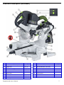
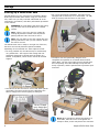
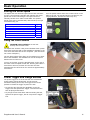
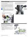
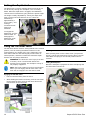
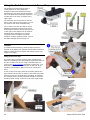
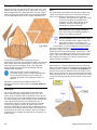
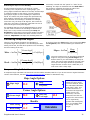
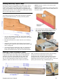
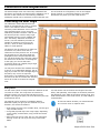
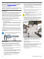
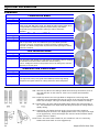
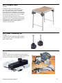
Kapex® KS 120
Miter Saw
Sliding Dual Compound Miter Saw
Supplemental User’s Manual
WARNING To reduce the risk of serious or fatal injury, read and understand
all safety precautions and instructions in this manual before using this tool.
Limited Warranty
30 Day Money Back Guarantee
We are so confident that you will thoroughly enjoy our tools, that
we offer a 30 day money back guarantee. If you are not
completely satisfied, your full purchase price will be refunded,
excluding all freight charges.
1+2 Limited Warranty
Festool USA offers a 3-year limited warranty, one of the longest
in the industry. This warranty is valid on the pre-condition that
the tool is used and operated in compliance with the Festool
operating instructions. Festool USA warrants that the specified
tool will be free from defects in materials and workmanship for a
term of 3 years from the date of purchase.
Conditions of 1+2 Limited Warranty
You are entitled to a free extended limited warranty (1 year + 2
years = 3 Years) for your Festool power tool. Festool USA is
responsible for all shipping costs during the first year of the
warranty. During the second and third year of the warranty, the
customer is responsible for shipping the tool to Festool. Festool
will pay for return shipping to the customer using UPS Ground
Service. All warranty service is valid 3 years from the date of
purchase on your receipt or invoice.
Excluded from the coverage under this warranty are: normal
wear and tear, damages caused by misuse, abuse, or neglect;
damage caused by anything other than defects in material and
workmanship. This warranty does not apply to accessory items
such as circular saw blades, drill bits, router bits, jigsaw blades,
sanding belts, and grinding wheels. Also excluded are "wearing
parts," such as carbon brushes, lamellas of air tools, rubber
collars and seals, sanding discs and pads, batteries, and Festool
gear (hats and t shirts).
The obligations of Festool USA in its sole discretion under this
warranty shall be limited to repair or replacement or a refund of
the purchase price for any Festool portable power tool that is
found to have a defect in materials or workmanship during the
warranty period. FESTOOL USA SHALL NOT BE LIABLE FOR ANY
CONSEQUENTIAL, INCIDENTAL OR SPECIAL DAMAGES
REGARDLESS OF THE THEORY OF LAW ON WHICH THE CLAIM IS
BASED. ALL WARRANTIES IMPLIED BY STATE LAW, INCLUDING
THE IMPLIED WARRANTIES OR MERCHANTABILITY AND FITNESS
FOR A PARTICULAR PURPOSE ARE HEREBY LIMITED TO THE
DURATION OF THREE YEARS.
Some states in the U.S. and some Canadian provinces do not
allow the limitations on how long an implied warranty lasts, so
the above limitation may not apply to you. This warranty gives
you specific legal rights, and you may also have other rights that
vary from state to state in the U.S. and from province to province
in Canada.
With the exception of any warranties implied by state or province
law as limited above, the foregoing express limited warranty is
exclusive and in lieu of all other warranties, guarantees,
agreements, and similar obligations of Festool USA. Festool USA
makes no other warranty, express or implied, for Festool portable
power tools. No agent, representative, distributor, dealer, or
employee of Festool USA has the authority to increase or
otherwise change the obligations or limitations of this warranty.
Repairs
If your Festool power tools require repair, you must contact our
Service Department at (800) 554-8741 for authorization and
address details. No collect shipments will be accepted. No Festool
hats, t-shirts or other wearables may be returned. Also contact
our Service Department at the telephone number listed above if
you have any questions about warranty claim procedures.
Returns
If you need to return your Festool tools for any reason, please return it to the dealer from which you originally bought the tool.
Liability Statement
This product has been built to the high standards of Festool.
Please do not attempt to operate or repair this equipment without
adequate training. Any use, operation, or repair in contravention
of this document is at your own risk. By acceptance of this
system you hereby assume all liability consequent to your use or
misuse of this equipment. Festool USA assumes no liability for
incidental, special, or consequential damage of any kind.
Equipment specifications, applications, and options are subject to
change at the sole discretion of Festool USA without notice.
Proprietary Notice
All drawings and information herein are the property of Festool,
TTS Tooltechnic Systems AG & Co. KG. All unauthorized use and
reproduction is prohibited.
Written and Illustrated by Rick Christopherson.
© 2008 TTS Tooltechnic Systems AG & Co. KG
All rights reserved. Printed in the United States of America and
Germany.
2
Festool USA is a division of Tooltechnic Systems, LLC.
Festool is a trademark and service mark of TTS Tooltechnic
Systems AG & Co. KG
Kapex and FastFix are registered trademarks of TTS Tooltechnic
Systems AG & Co. KG
MiterFast is a trademark of TTS Tooltechnic Systems AG & Co. KG
www.festoolusa.com
Kapex KS120 Miter Saw
Contents
Limited Warranty .............................................2
30 Day Money Back Guarantee ......................... 2
1+2 Limited Warranty ..................................... 2
Conditions of 1+2 Limited Warranty .................. 2
Repairs ......................................................... 2
Returns......................................................... 2
Liability Statement ......................................... 2
Proprietary Notice........................................... 2
About This Manual............................................3
Tool Symbols ................................................. 3
General Power Tool Safety Warnings ...............4
Work Area Safety ........................................ 4
Electrical Safety .......................................... 4
Personal Safety........................................... 4
Power Tool Use and Care.............................. 4
Service ...................................................... 5
Specific Safety Rules for Miter Saws .................. 5
Respiratory Exposure Safety Warnings .............. 5
Tool Description ...............................................5
Technical Specifications ................................... 5
Intended Use ................................................. 6
Functional Description ..................................... 6
Setup................................................................8
Setting Up a New Miter Saw ............................. 8
Changing Sawblades ....................................... 9
Transporting the Saw .....................................10
Dust Extraction .............................................10
Basic Operation ..............................................11
Setting the Motor Speed .................................11
Using the Laser Guides...................................11
Power Trigger and Plunge Release ................... 11
Using the Hold Down Clamp ........................... 12
Setting the Miter Angle .................................. 12
Setting the Bevel Angle ................................. 13
Using the Auxiliary Fence ............................... 13
Setting the Depth Limit.................................. 14
Using the Tall Miter Latch............................... 14
Using the MiterFast Tool ................................ 15
Using the Bed Extensions and Crown Stops ...... 16
Cutting Techniques ........................................17
Miter Cuts.................................................... 18
Bevel Cuts ................................................... 18
Depth Limited (Dado/Half-Lap) Cuts ................ 19
Compound Miter Cuts .................................... 20
Calculating Compound Angles...................... 21
Compound Angle Calculator ........................ 21
Crown Moulding............................................ 22
Adding Auxiliary Fence Faces.......................... 23
Making a Zero-Clearance Insert ...................... 23
Calibration and Adjustment............................24
Calibrating the Miter Angle ............................. 24
Calibrating the Bevel Angle ............................ 26
Calibrating the Lasers.................................... 28
Troubleshooting .............................................29
Optional Accessories ......................................30
Sawblades ................................................... 30
MFT/3-Kapex Table ....................................... 31
Bolt Down (Clamping) Kit............................... 31
Crown Stop.................................................. 31
About This Manual
Save These Instructions
It is important for you to read and understand this manual. The
information it contains relates to protecting YOUR SAFETY and
PREVENTING PROBLEMS. The symbols below are used to help you
recognize this information.
WARNING!
Indicates a potentially hazardous
situation which, if not avoided, could
result in death or serious injury.
CAUTION!
Indicates a potentially hazardous
situation which, if not avoided, could
result in minor or moderate injury.
Laser
Radiation
This symbol is used on the machine and
in this manual to signify the possibility of
laser radiation.
NOTICE:
Indicates a potential situation which, if
not avoided, can result in property
damage or damage to the tool.
Note:
Indicates information, notes, or tips for
improving your success using the tool.
Supplemental User’s Manual
Tool Symbols
V
W
Hz
~
no
Ø
Volts
Watts
Hertz
Alternating Current (AC)
No-load Speed
Diameter
Class II Double Insulated
Designated Danger Zone.
Avoid positioning hands,
fingers, or arms in the area
designated by this symbol.
3
General Power Tool Safety Warnings
WARNING! Read all safety warnings and
instructions. Failure to follow the warnings and
instructions may result in electric shock, fire, and
serious or fatal injury.
CAUTION! Laser Radiation. This product contains a
Class II laser. Do not look directly into the laser beam.
Power ≤ 1mW, Wavelength: 640 to 660 nm
Save all warnings and instructions for future reference.
Work Area Safety
►
►
Keep your work area clean and well lit. Cluttered or
dark work areas invite accidents.
Do not operate power tools in explosive atmospheres,
such as in the presence of flammable liquids, gases,
►
or dust. Power tools create sparks which may ignite the
dust or fumes.
Keep children and bystanders away while operating a
power tool. Distractions can cause you to lose control.
Electrical Safety
►
►
►
►
►
Power tool plugs must match the outlet. Never modify
the plug in any way. Do not use any adapter plugs
with power tools. Unmodified plugs and matching outlets
will reduce risk of electric shock.
Avoid body contact with earthed or grounded surfaces
such as pipes, radiators, ranges and refrigerators.
There is an increased risk of electric shock if your body is
earthed or grounded.
Do not expose power tools to rain or wet conditions.
Water entering a power tool will increase the risk of electric
shock.
Do not abuse the cord. Never use the cord for
carrying, pulling, or unplugging the power tool. Keep
cord away from heat, oil, sharp edges or moving
parts. Damaged or entangled cords increase the risk of
electric shock.
When operating a power tool outdoors, use an
extension cord suitable for outdoor use. Use of a cord
for outdoor use reduces the risk of electric shock.
►
►
►
►
If operating a power tool in a damp location is
unavoidable, use a ground fault circuit interrupter
(GFCI) protected supply. Use of a GFCI reduces the risk
of electric shock.
Never use an extension cord that is damaged,
including cuts, exposed wires, or bent/missing
prongs. Damaged extension cords increase the risk of fire
or electric shock.
Use only extension cords rated for the purpose.
Use only extension cords rated for the amperage of
this tool and the length of the cord. Using too small of
an extension cord can cause the cord to overheat.
Extension Cord Ratings
Cord Length
Size (AWG)
<25 Ft.
14
25-50 Ft.
12
50-100 Ft.
10
>100 Ft.
Not recommended
Personal Safety
►
►
►
Stay alert, watch what you are doing, and use
common sense when operating a power tool. Do not
use a power tool while tired or under the influence of
drugs, alcohol, or medication. A moment of inattention
while operating power tools may result in serious personal
injury.
Use personal protective equipment. Always wear eye
protection. Protective equipment such as dust mask, nonskid safety shoes, hard hat, or hearing protection used for
appropriate conditions will reduce the risk of personal
injuries. (Eye protection must comply with ANSI Z87.1)
Prevent unintentional starting. Ensure the switch is in
the off-position before connecting to power source,
picking up, or carrying the tool. Carrying power tools
with your finger on the switch or energizing power tools that
►
►
►
►
have the switch on invites accidents.
Remove adjusting key or wrench before turning the
power tool on. A wrench or a key that is left attached to a
rotating part of the tool may result in personal injury.
Do not overreach. Keep proper footing and balance at
all times. This enables better control of the tool in
unexpected situations.
Dress properly. Do not wear loose clothing or jewelry.
Keep your hair, clothing, and gloves away from
moving parts. Loose clothes, jewelry, or long hair can be
caught in moving parts.
If devices are provided for the connection of dust
extraction and collection facilities, ensure these are
connected and properly used. Use of dust collection can
reduce dust-related hazards.
Power Tool Use and Care
►
►
►
►
4
Do not force the power tool. Use the correct power
tool for your application. The correct power tool will do
the job better and safer at the rate for which it is designed.
Do not use the power tool if the switch does not turn
it on and off. Any power tool that cannot be controlled with
the switch is dangerous and must be repaired.
Disconnect the plug from the power source before
making any adjustments, changing accessories,
transporting, or storing the tool. Such preventive safety
measures reduce the risk of starting the tool accidentally.
Store idle tools out of reach of children and do not
allow persons unfamiliar with the power tool or these
instructions to operate the power tool. Power tools are
dangerous in the hands of untrained users.
►
►
►
Maintain power tools. Check for misalignment or
binding of moving parts, breakage of parts and any
other condition that may affect the power tool’s
operation. If damaged, have the power tool repaired
before use. Many accidents are caused by poorly
maintained power tools.
Keep cutting tools sharp and clean. Properly maintained
tools with sharp cutting edges are less likely to bind and are
easier to control.
Use the power tool, accessories, and tool bits etc. in
accordance with these instructions, taking into
account the working conditions and the work to be
performed. Use of the power tool for operations different
from those intended could result in a hazardous situation.
Kapex KS120 Miter Saw
Service
►
To reduce the risk of serious or fatal injury, never
open the motor housing. Have your power tool
serviced only by a qualified repair person using only
identical replacement parts.
►
Any repairs to the laser must be carried out by the
laser manufacturer or by an authorized agent of the
laser manufacturer. Never attempt to replace the laser on
this tool with a different type of laser.
Specific Safety Rules for Miter Saws
►
►
►
►
►
►
►
►
►
►
►
To reduce the risk of serious or fatal injury, never alter
or misuse the power tool.
Be certain the miter saw is mounted or securely placed
on a level, firm work surface before using. A level and
firm work surface reduces the risk of the miter saw becoming
unstable or tipping.
Make sure all controls and clamping handles are
secured before starting any operation. Unsecured
clamps or adjustment handles can cause the saw and/or
workpiece to move unexpectedly.
Always unplug the saw before servicing or changing
the sawblade.
Never remove or disable the blade guard. Inspect the
blade guard before use. Repair or replace a damaged or
improperly functioning blade guard before further use.
Keep hands out of the path of the sawblade. Never
cross your hand over intended line of cutting.
Supporting the workpiece “cross handed” e.g. holding the left
side of the workpiece with your right hand, is very
dangerous.
Do not reach in back of the moving saw blade with
either hand to remove wood scraps, hold down or
support the workpiece, or for any other reason. The
proximity of the spinning saw blade to your hand may not be
obvious and you may be seriously injured.
Use clamps to support workpiece whenever possible.
Do not use this saw to cut pieces that are too small to
be securely clamped.
Clamp the offcut side of the workpiece when using a
length stop. An unsecured offcut can bind between the
length stop and the saw blade.
If securing the workpiece by hand, you must always
keep hands outside of “No Hand” area as marked with
a symbol on the base. Your hand, if placed inside the “No
Hands” region, can easily slip or be pulled into the blade.
Support long workpieces to prevent them from tipping.
A tipping workpiece can lift up and contact the spinning
sawblade, or bring the operator’s hand upward into the
blade.
For proper control, never “pull” the saw through the
cut, always chop or push cut. See page 17 of this manual.
Cut only one workpiece at a time. Multiple workpieces
cannot be adequately clamped or braced and may bind on
the blade or shift during cutting.
Keep workpieces firmly against the rear fence when
cutting. Never cut workpieces that do not lay flat or
are curved in any way. A curved workpiece can be grabbed
by the blade and propelled back against the fence.
Inspect workpieces for nails or foreign objects. Make
sure there are no tools or foreign objects on the saw.
Do not cut round stock unless it is clamped in such a
way as to prevent rotation. Round stock will tend to roll
while it is being cut.
Use only sawblades recommended by the
manufacturer and designed for use with the saw, with
a 30mm arbor bore, a 260mm diameter, and a
maximum thickness of 2mm. Be sure that the speed
marked on the saw blade is at least equal to the speed
marked on the saw. Do not use high speed steel saw
blades.
Select the correct saw blade for the material to be cut.
Do not use the saw to cut materials other than those
recommended by the manufacturer. Never force the tool
or attachment to do a job for which it was not designed.
Never use this saw for cutting ferrous metals.
Never use saw blades that are damaged or deformed.
Never use a dull sawblade. A dull sawblade places undue
stress on the saw and the workpiece and can increase the
risk of kickback.
Make sure the sawblade is securely installed and is not
backward. The arrow on the blade should match the
direction of the arrow marked on the tool.
►
►
►
►
►
►
►
►
►
►
Respiratory Exposure Safety Warnings
Substantial or repeated inhalation of dust and other airborne
contaminants, in particular those with a smaller particle size,
may cause respiratory or other illnesses. Various dusts
created by power sanding, sawing, grinding, drilling and other
construction activities contain chemicals or substances known
(to the State of California and others) to cause cancer, birth
defects or other reproductive harm. Some examples of these
chemicals/substances are:
►
►
lead from lead-based paints;
crystalline silica from bricks, cement, and other masonry
products;
►
►
arsenic and chromium from chemically-treated lumber; and
some wood dusts, especially from hardwoods, but also from
some softwoods such as Western Red Cedar.
The risk from these exposures varies, depending on how often
you do this type of work. To reduce your exposure to these
chemicals: work in a well ventilated area and use a properly
functioning dust extraction system. When the inhalation of
dust cannot be substantially controlled, i.e., kept at or near
the ambient (background) level, the operator and any
bystanders should wear a respirator approved by NIOSH for
the type of dust encountered.
Tool Description
Technical Specifications
Power Consumption
Motor Speed
Arbor Diameter
Max. Blade Size
Max. Depth (std.)
1600 Watts (13 amps @ 120 volts)
1400 - 3400 RPM (no load)
30 mm
260 mm (10.25”) dia., 2mm (5/64”) thick
88 mm (3.46”)
Max. Depth (tall)
Max. Depth at 45° Bevel
Max. Width at 90° Miter
Max. Width at 45° Miter
Weight
120 mm (4.75”) at 60 mm (2.3”)
55mm (2.2”)
305mm (12”)
210mm (8.25”)
21.5 kg (47.3 lbs)
All metric dimensions are controlling. The arbor diameter is critical for safe operation, and is presented in metric only.
Supplemental User’s Manual
5
Intended Use
The Kapex miter saw is intended to cut wood, plastic,
aluminum, and similar materials. All applications beyond
this are regarded as improper use. The tool should not be
altered or used for any other purpose other than as
specified in these operating instructions. Using the tool in
contravention to this manual may lead to injury and will
void your warranty. The user shall be responsible and
liable for accidents, injuries, and property damage
resulting from misuse or abuse of this tool.
Functional Description
Item Name or Description
6
Ref. Page(s)
Item Name or Description
Ref. Page(s)
A
Bevel Gauge and Pointer (both sides)
12, 18
J
B
Power Cord Storage
10
K
Main Handle
11, 17
C
Tall Miter Latch
14, 22
L
Laser Dust Lens
28
D
Tall Miter Release
14, 22
M
Blade Guard
9
E
Bevel Lock
12, 18
N
Miter Stop Release Lever
12, 15, 18, 20
F
Bevel Range Selector
12, 18
O
Miter Lock Lever
12, 15, 18, 20
G
Dust Extraction Port
10
P
Miter Gauge and Pointer
12, 15,
9
Q
MiterFast™ Angle Tool and Storage
15
®
H
FastFix
I
Trigger Lock
Arbor Lock
Power Switch/Trigger
9, 10, 11
11
Kapex KS120 Miter Saw
Functional Description (continued)
Item Name or Description
Ref. Page(s)
Item Name or Description
Ref. Page(s)
A
Bevel Gauge and Pointer (both sides)
12, 18
S
Speed Control Dial (see inset)
11
I
Trigger Lock
9, 10, 11
T
Laser On/Off Button (see inset)
11
J
Power Switch/Trigger
9, 10, 11
U
Depth Limit Adjustment Knob
13
K
Main Handle
11, 17
V
Slide Lock Knob
10
L
Laser Dust Lens
28
W
Head Lock Knob
10
M
Blade Guard
9
X
Auxiliary Fence
13
N
Miter Stop Release Lever
12, 15, 18, 20
Y
Main Fence
13, 23
O
Miter Lock Lever
12, 15, 18, 20
Z
Table Inserts
23
R
Bevel Adjustment Knob
12, 18
Supplemental User’s Manual
7
Setup
Setting Up a New Miter Saw
Congratulations on your purchase of a new Kapex Sliding
Dual Compound Miter Saw. Before using your new miter
saw, make sure you fully read and understand all of the
instructions, precautions, and safety information presented
in this manual.
►
For a more permanent installation, the Kapex saw is
equipped with 4 bolt holes, to be used with ¼-20 (M6)
bolts to securely bolt the saw to a work table.
WARNING! To avoid tipping the miter saw during
use, the miter saw must be placed on a stable
surface.
Note: There is a 2.5 mm hex key needed for
making adjustments located in the Styrofoam
packing material. Take care not to lose it.
Note: You may want to save the original box and
packing material in case you ever need to send in
the saw for service.
The KS120 miter saw is ready to use right out of the box,
but there are several placement options available,
depending on the intended use. These options include:
►
►
For truly portable use, the KS120 may be used directly
on a jobsite floor. The height of the cutting bed was
specifically designed to coincide with the height of a
Festool #1 Systainer, which can be used as an outfeed
support.
►
The Kapex saw was specifically designed to be
compatible for operation on a Festool Multi-Function
Table (MFT). The four feet under the saw coincide with
the hole spacing of an MFT tabletop to keep the saw
firmly in position, and the optional bolt kit permits quick
mounting.
The KS120 can also be used on a level and stable jobsite
work table. The saw must be securely clamped to the
table to help prevent it from tipping or falling off.
Note: When clamping or bolting the Kapex to a
work table, take care not to over tighten the
clamps or bolts, as this may distort the saw base.
8
Kapex KS120 Miter Saw
Changing Sawblades
WARNING! To reduce the risk of injury from
contact with a moving part, always unplug the
saw before changing blades.
1.
2.
4.
Without pushing down on the trigger lock, pull up on
the trigger to release the blade guard.
5.
Raise the blade guard out of the way and remove the
outboard arbor flange and sawblade from the arbor.
6.
Inspect the friction lining on the two arbor flanges. If
the lining is damaged, replace the flanges, as this can
cause the sawblade to wobble.
®
Push in and rotate the FastFix arbor lock clockwise.
This prevents the arbor from turning and also disables
the motor.
Loosen the clamping screw on the arbor bolt guard,
and rotate the guard away from the arbor bolt. (The
combination hex key is stored on the back of the saw
by the power cord.)
Note: The friction lining on the arbor flanges
grips the blade, but also permits the blade to slip
slightly, in the event of a binding condition.
WARNING! When installing a new blade, make
sure the arbor bolt is properly tightened and the
rotation direction of the sawblade matches the
rotation direction indicated on the saw (see image
below).
3.
7.
Make sure the blade is oriented correctly and install
the blade onto the inboard arbor flange.
8.
Replace the outboard arbor flange, tighten the arbor
bolt, and then unlock the FastFix arbor lock.
Unscrew the arbor bolt by turning it clockwise. The
arbor bolt is a left-hand thread and turns the
opposite of a standard screw.
Supplemental User’s Manual
9
Transporting the Saw
When The Kapex miter saw is collapsed for transport, it is
very well balanced and easily carried using the integrated
carrying handles.
1.
Unplug the saw and coil the power cord on the reel at
the rear of the saw.
4.
Set the miter angle to 60° and push down on the miter
lock lever.
5.
Pick up the saw from the rear by grasping the two
handle points as shown below.
WARNING! To reduce the risk of unexpectedly
starting the saw, make sure the saw is
unplugged.
2.
Pull the power trigger (without depressing the trigger
lock) and lower the motor head down. When the head
is in the down position, push in on the Head Lock Knob
(see the picture to the upper right).
3.
Push the motor head all the way to the rear of the saw
and tighten the Slide Lock Knob.
Dust Extraction
The Kapex saw can be connected to a dust extractor to
substantially reduce dust during operation. The dust port
swivels to either side, and accepts either a 27 or 36 mm
Festool hose. The 27 mm hose fits inside the dust port, or
the 36 mm hose fits over the outside of the dust port.
Note: For optimal dust extraction performance,
Festool recommends using a 36 mm hose.
10
Kapex KS120 Miter Saw
Basic Operation
Setting the Motor Speed
The Kapex saw has electronic speed control with soft-start
circuitry. The electronic controller will maintain the motor
speed even as the load changes. The speed control is
infinitely variable from 1400 to 3400 RPM. The optimal
speed of the saw is predominately determined by the type
of material being cut.
Material
Soft wood products and veneer plywoods
Hardwood products
Plastic laminate countertops
Hard plastics
Soft plastics
Aluminum
Turn the speed control dial to the number shown in the
table to the left. The speeds listed in the table are just
rough guidelines, and actual results may vary.
Speed
6
3-6
6
3-5
1-4
4-6
Using the Laser Guides
CAUTION! Laser Radiation. Do not look
directly into the laser beam.
The Kapex saw contains a low-power solidstate laser system
that scans across the path of the sawblade to indicate to the
user where the blade will cut the workpiece. (The laser does
not cut the workpiece.)
The two laser beams shine down on the workpiece on either
side of the sawblade. The sawblade will cut the workpiece
between the two laser lines.
To turn on the laser, press the On/Off button on the rear of
the motor near the speed control dial. Pressing the button a
second time will turn the laser off. The laser will also
automatically shut off if left on for more than approximately
30 minutes.
Power Trigger and Plunge Release
The power trigger turns on the saw but also releases the
motor head to plunge downward. To help prevent
accidental starting of the saw, the trigger lock must be
pushed to release the trigger to power the saw.
►
►
To start the saw (activate the sawblade), press the
trigger lock and squeeze the trigger. The saw head can
then be plunged downward.
To plunge the saw head down without starting the saw,
squeeze the power trigger, but do not press the trigger
lock.
Supplemental User’s Manual
11
Using the Hold Down Clamp
The hold down clamp fits in a socket on either the left or
right sides of the saw. To insert or remove the clamp,
rotate it to the rear to unlock it from the socket, as shown
in the first image below. To lock the clamp in its socket,
rotate it to the forward position, as shown in the center
image below. To secure the workpiece, press down on the
green knob and rotate the locking handle down, as shown
in the image on the right, below. To release the clamp,
rotate the locking lever up.
Setting the Miter Angle
A mitered cut is where the saw head is rotated side-toside. The Kapex saw is capable of mitering 50° to the left
and 60° to the right. Positive stops are located at 0, 22½,
30, and 45 degrees. The miter gauge pointer also includes
½ degree vernier indices for accurately setting the miter
angle to half-degree values. Also refer to “Using the
MiterFast Tool“ described on page 15.
1.
2.
Press down on the miter stop release lever, and rotate
the miter to the desired angle.
Release the miter lock by lifting up on the handle.
►
►
3.
To stop at one of the preset positive lock miter
positions, release the miter stop lever just before
reaching the angle, and the miter stop will click as it
locks into position.
To set the miter angle to ½ degree between the
primary angles, line up the ½° vernier indices with
the adjacent angle index marks. (The example
shown to the left represents 20½°.)
When the desired miter angle is set, engage the miter
lock by pressing down on the miter lock lever.
Note: When setting a miter angle very close to
one of the miter stops (for example, at 45½° ),
keep holding down the miter stop release lever
until you fully engage the miter lock lever, to
prevent the miter angle from jumping to the
nearby miter stop position.
12
Kapex KS120 Miter Saw
Setting the Bevel Angle
A beveled cut is where the saw head is tilted to the left or
right from vertical. The Kapex saw is capable of beveling
up to 47° to the left and right.
3.
Rotate the bevel adjustment knob until the bevel index
pointer is pointing to the desired angle. (There is a
duplicate pointer on either side of the saw.)
The bevel range selector engages a series of angle stops.
The selector has three settings. The first setting, (0-45°)
limits the bevel travel between 0 degrees and 45 degrees
to the left. The second setting (±45°) limits the bevel
travel between 45 degrees to the left and 45 degrees to
the right. The last setting (±47°) limits the bevel travel to
the full extent of the saw, which is 47 degrees to the left
and to the right.
4.
Lower the bevel lock lever.
NOTICE: These settings are not hard-limits, and
turning the bevel adjustment knob into one of the
limit settings will cause the spring loaded limit to
be bypassed. However, it should be noted that
doing so can cause premature wear to the bevel
limits.
1.
Release the bevel lock by lifting the lever.
2.
As necessary, turn the bevel range selector to the
desired range.
Using the Auxiliary Fence
The auxiliary fence provides support for taller workpieces.
The two halves of the fence can be slid toward or away
from the blade, or removed completely. Performing
beveled cuts requires the auxiliary fence to be moved
away from the blade area.
►
►
To move the auxiliary fence, lift the locking lever, slide
the fence, then lower the locking lever.
To remove the auxiliary fence, lower the limit screw by
turning it clockwise, then slide the fence out of the
retaining slot.
Supplemental User’s Manual
13
Setting the Depth Limit
The depth limit is used for making partial cuts that do not
cut all the way through the workpiece, such as making
dados. When the depth limit is engaged, the sawblade’s
vertical travel is limited from going below the preset height.
The height is easily adjustable by turning the depth limit
knob. Turning the knob clockwise ¼-turn raises the
sawblade by
approximately 1
mm (0.040”), and
turning it
counterclockwise
lowers the
sawblade.
To engage the
depth limit, pull the
knob forward. To
disengage the
depth limit, push
the knob back.
Using the Tall Miter Latch
The tall miter latch is used for cutting boards in the vertical
position, such as mitering baseboard material. In this
cutting position, the height of the cut is maximized. The
miter latch holds the saw head slightly forward from its
normal position, and also increases the maximum depth
that the saw can plunge downward.
WARNING! To reduce the risk of injury from loss
of control, never cut tall boards without the
auxiliary fence installed. The workpiece can tip if
not properly supported.
Note: The bevel position must be at zero degrees
before you can engage the tall miter latch. The
latch will not engage if the saw head is tilted.
Releasing the Tall Miter Latch
While pressing down on the release lever (see previous
image), pull the saw head away from the fence. The tall
miter latch will spring to the vertical position when it
releases.
Cutting the Workpiece
Stand the workpiece up against the fence and plunge the
saw head down into the cut.
Engaging the Tall Miter Latch
1.
Pull the saw head away from the fence.
2.
While holding the latch lever down, push the saw head
back toward the fence until the tall miter latch locks
into the back of the saw head.
14
Kapex KS120 Miter Saw
Using the MiterFast Tool
The MiterFast™ angle transfer tool converts a corner angle
measurement into a miter setting. The miter line in the
center of the tool is always at the midpoint of the two
angle arms, and when lined up with the saw’s laser,
provides the proper miter angle for the measured corner.
4.
Place the MiterFast tool on the saw with one of the
arms up against the fence.
5.
Turn on the laser for the saw. (Refer to Using the Laser
Guides on page 11.)
6.
Adjust the miter angle of the saw (refer to Setting the
Miter Angle on page 12) until either of the laser beams
line up with the miter line on the MiterFast tool.
7.
Lock the miter setting on the saw.
8.
Fold up the MiterFast tool and return it to its storage
position in the base of the saw.
Measure the Corner
►
►
For measuring an
arms as shown in
For measuring an
arms as shown in
outside corner, extend the extension
the image below.
inside corner, retract the extension
the second image below.
1.
Loosen the lock knob on the MiterFast tool.
2.
Place the MiterFast tool in (or on) the corner and slide
the lock knob forward to expand the arms.
3.
When the arms are lined up with the corner walls,
retighten the lock knob.
Supplemental User’s Manual
15
Using the Bed Extensions and Crown Stops
The optional bed extensions provide a
useful platform for using additional
workpiece control accessories as well as
extending the size of the bed of the Kapex
saw. The optional bed extension accessory
includes the crown stop, as shown to the
upper right.
The extension can be mounted to the left
side or right side of the saw’s bed, or if two
are used, to both sides simultaneously.
The T-channel can also be used to secure
additional clamping elements such as the
Festool Quick Clamp or Screw Clamp shown
to the right. These clamps can be used for
clamping larger workpieces, or used in
conjunction with the Kapex hold down
clamp for multiple clamping needs, such as
the dado example shown on page 19.
Installation
To install the bed extension, place the edge into the Vchannel of the Kapex bed, position the extension forward or
back as needed, and then tighten the clamping knob (see
image to the right).
Setting up the Crown Stop
The crown stop is used for cutting crown moulding and
holds the moulding at the desired angle against the fence of
the saw so that it can be cut using a standard miter cut
(refer to the Crown Moulding discussion on page 22). The
stop slides forward or back depending on the size of the
moulding, and clamps in place to serve as a secondary
fence.
To set up the crown stop, place the moulding against the
fence and bed of the saw, as shown in the lower left image,
slide the crown stop up against the moulding, and tighten
the clamping knob. Use the hold down clamp to secure the
moulding while cutting, as shown in the lower right image.
16
Kapex KS120 Miter Saw
Cutting Techniques
There are three basic cutting techniques for sliding miter
saws, but only two are proper and authorized. These are
Chop-Cut, Push-Cut, and the improper method is a Pull-Cut.
that the sawblade is cutting the wood in two different
manners, and there will frequently be a rough edge at the
transition from one type of cut to the other.
Chop-Cut
Tips for Successful Cutting
A chop-cut is used for cutting narrow or tall stock, where
the front edge of the workpiece is behind the center of the
sawblade. For this type of cut, the saw head is brought
straight down into the cut.
►
►
Push-Cut
A push-cut is used for cutting wider boards, but is also
usable in most situations where a chop-cut could be used.
For this type of cut, the saw head is pulled out toward the
operator, plunged downward, and the primary cutting of the
workpiece occurs as the saw head is being pushed back
toward the rear of the saw (as shown in the picture below).
►
►
Pull-Cut (Improper Method)
WARNING! To reduce the risk of injury from loss
of control, never use the pull-cut technique.
The third type of cut, called a pull-cut, or climb-cut, should
be avoided for both safety reasons and for cutting
performance reasons. This type of cut is made by plunging
the saw head down, and then pulling it forward. The danger
of this type of cut is that the sawblade wants to self-feed
into the cut (called climb-cutting), and this can cause the
saw head to jump forward unexpectedly. The reason this
type of cut results in a poor quality cut is because it is using
two different actions for the same cut. It starts out with a
plunge-cut, and then finishes with a climb-cut. This means
►
►
►
►
For more accurate cuts, mark your cutting length with
a thin pencil line. A thick line will result in a less
accurate cut length.
When fitting one piece to another, it may be helpful to
make the initial cut slightly long, and then trimming
the cut to final length after test-fitting the piece.
When cutting a new board, cut off the original factory
end to ensure a square, fresh end, before measuring
for your final length.
When cutting small trim, use a zero clearance fence
and/or insert to prevent small offcuts from being
thrown behind the fence by the windage from the
spinning blade (see page 23).
When cutting multiple pieces of varying lengths from
a limited supply of stock, always cut the longest
pieces first, and cut the remaining pieces from the
leftovers.
Do not force the blade through the cut. A cleaner
edge will be achieved with a steady, moderate feed
rate.
A chop-type of cut yields the lowest tearout on the
front and top edges of the cut, but the most tearout
on the rear side of the cut.
A push-type cut yields moderate tearout on the top
surface, but the best cut edge.
Diagram of Push-Cut Method
Supplemental User’s Manual
17
Miter Cuts
Miter cuts are used when a board needs to be cut at an
angle across its width. The most common application for a
miter cut is for joining two boards to form a corner without
endgrain showing. The miter angle is one-half of the
corner angle. So for a 90° corner, for example, the miter
angle is 45°.
►
►
When marking the length of the workpiece, use a sharp
pencil to draw a thin line. The thicker the line, the more
difficult it will be to cut accurately on the line.
When marking a workpiece length to match a wall or
other structure, use a utility knife to mark the cut with a
small nick. This is more accurate than a pencil line.
Miter Angles for Polygons
Number of sides Corner Angle Miter Angle
3
4
5
6
7
8
–
–
–
–
–
–
Triangle
Square
Pentagon
Hexagon
Heptagon
Octagon
120
90
72
60
51.4
45
60
45
36
30
25.7
22.5
For even the most experienced woodworkers, cutting
accurate and tight fitting miters can be problematic. The
following are some tips for making accurate miters.
►
►
►
Clamp the workpiece down. Because the sawblade is
cutting at an angle with the workpiece edge and fence, it
will tend to move the workpiece sideways, in the
direction of the cut, as the cut progresses. This can
result in a cut that is not straight, or the angle of the cut
may be off.
Cut slowly. Cutting too rapidly can cause the sawblade to
deflect as it encounters varying densities in the
woodgrain.
Use a chop-cut only for narrow miters. When in doubt,
use a push-cut.
►
If a utility knife is used to mark the cut, you can use a
method called “Sneaking up on the cut.” This is where
you make an initial cut longer than needed, and
continually make very small re-cuts until the cut line
splits through the center of the nick you made with the
utility knife.
Bevel Cuts
Bevel cuts are used when a board needs to be cut at
an angle across its thickness. The most common
application for a bevel cut is for constructing a box or
similar structure.
easy to inadvertently push the saw head down or pull it up
as you feed the saw into the cut. This will result in a crooked
cut.
►
Place the workpiece on the saw with the best-side down.
Because of the angle of the blade teeth exiting the workpiece
on the top side of the cut, there will be slightly more tearout
on the top, especially on the sharper edge.
The following are tips for making accurate bevel cuts:
►
►
►
Clamp the workpiece down. If the workpiece is not
held firmly, the blade will tend to pull the workpiece
into the cut and up the blade.
For best results, use only a push-cut.
Take care not to deflect the saw head sideways.
Because the saw head is tilted to the side, it can be
18
Kapex KS120 Miter Saw
Depth Limited (Dado/Half-Lap) Cuts
Half-Lap Joint
WARNING! Never attempt to install or use a
dado blade in the Kapex saw. Using either a
stacked-dado or wobble-dado blade will exceed
the capacity of the arbor, and the blade may
impact the saw’s guards, resulting in personal
injury and damage to the saw.
A dado is a special type of cut where the depth of the cut
does not go all the way through the workpiece. One
common example of this type of cut is for making halflapped joints, which is shown to the right and described
below. In a half-lap joint, material is removed from the
intersection of both workpieces comprising the joint. When
the joint is assembled, the pieces overlap, creating a
strong joint, but unlike a full-lap joint, the thickness of the
joint is equal to just the thickness of the workpieces.
Clamping
Depth Setting
For making a half-lap joint, it is necessary to set the saw’s
cutting depth to be exactly in the center of the workpiece
thickness. The most accurate way of finding the center of a
board is to trim from both sides until the two cuts meet.
Use a piece of scrap wood that is the same thickness as
the actual workpiece. Starting with a depth setting that
you know to be less than half the workpiece thickness,
make a cut from the top side, and then flip the piece over
and make a second cut, as shown below by the Red color.
Gradually lower the depth of cut and repeat these two cuts
until the two cuts meet, and the spine reaches a zerothickness. This is exactly the center of the workpiece.
It is important that both the fence spacer and workpiece
are securely clamped to the saw for cutting. Use the Kapex
Hold Down Clamp (see page 12) to clamp the fence
spacer, and use an auxiliary clamp, such as a Festool
Quick Clamp or Screw clamp (see page 16) to secure the
workpiece.
Fence Spacer
The center of the sawblade is 50 mm (2”) forward of the
saw’s fence, which results in the curved ramp at the rear
of the cut shown in the image below. To account for this
and remove the radius at the end of the cut, add a 50mm
(2”) spacer in front of the fence, and clamp it in place with
the Kapex hold down clamp as shown to the right.
Supplemental User’s Manual
Cutting the Dado
Before cutting the dado, mark the right and left sides of
the cut to indicate how wide the dado needs to be. Then
make successive kerf-cuts between the lines until all the
material between the lines is removed. The closer together
each of these successive cuts are, the smoother the
bottom of the dado will be. For best results, clean the
bottom of the dado with a sharp chisel.
19
Compound Miter Cuts
Compound miter cuts are where the saw is both in a miter
position and a bevel position at the same time. There are
several applications for compound miter cuts, but cutting
crown moulding and sloped miters are common examples.
The example below shows a very simple birdfeeder roof.
Slope
The Slope angle is the angle that each piece makes with
respect to the base of the corner, such as the ceiling or
floor in the examples provided here. For a roof-like
structure, this would be the pitch of the roof.
For crown moulding, this would be the
compliment of the “Spring Angle” of the
moulding. Common spring angles for
mouldings are 38/52 and 45/45.
Determining the Corner Angle of Polygons
The corner angle for standard polygons is
shown in the table on page 18.
Using the MiterFast Tool to Find a Corner Angle
The greatest challenge with compound miters is
determining the proper saw settings to achieve the desired
miter angle. These saw settings can be found in look-up
tables for standard mouldings, but for non-standard
angles, determining the proper saw settings requires
mathematical calculation.
Note that there are several methods for
accurately cutting crown moulding depending on
the circumstances. Make sure to review the
methods described in the applicable section on
page 21.
For non-standard corner angles, such as a
room that is slightly out of square, the
MiterFast tool can be used to determine the
corner angle. To use the MiterFast tool to measure
the corner angle, follow the “Using the MiterFast Tool”
procedure on page 15, but instead of making the cut,
record the saw’s miter setting angle. This angle is ½ the
corner angle, so multiplying by 2 will give you the corner
angle. (The compound angle calculator on page 21 also
has an option for letting you enter this angle directly
without needing to double it.)
Determining the Slope of a Pyramid (Polyhedron)
A polyhedron is a pyramid that can have any number of
sides. The easiest method for determining the slope of the
polyhedron is by measuring the Drop and Projection of
one face. These are the distances from the center-to-theedge, and the base-to-the-point of the pyramid. Note that
with a polyhedron with an odd number of sides, the center
is found by drawing bisecting lines as shown in the image
below.
Calculating compound miter settings requires two
parameters from the desired joint: the corner angle and
the slope.
Corner Angle
The corner angle is the angle between the two pieces,
when viewed looking straight down on the joint. The
corner angle is relatively easy to determine, but it is also
the value that can cause the greatest amount of confusion
for many woodworkers. That’s because most woodworkers
view angles differently than a mathematician will. A
woodworker typically considers both inside and outside
corners as 90 degrees (with a 45 degree miter) even
though a mathematician would make the distinction that
one corner is 90 degrees and the other is 270 degrees. To
be consistent with miter saw settings, the corner angle is
measured from a straight line between the two pieces, as
shown above.
20
Kapex KS120 Miter Saw
necessarily coincide with the “points” or “Tails” of the
moulding. The slope is measured from the back-side of
the moulding, regardless how long the tails of the
moulding may extend (see image below).
Determining the Slope of Crown Moulding
As was mentioned previously, the slope of a crown
moulding is the compliment of its ”Spring Angle” (the
spring angle is measured relative to the wall, and the slope
is measured relative to the ceiling). The two common
spring/slope angles of crown moulding are 38/52 and
45/45. The reason why these angles are represented by
dual numbers is because the actual angle depends on
which direction the moulding is oriented. For example,
turned one way, the slope is 38 degrees, but turned the
other way, the slope is 52 degrees. Note that the sum of
these two angles is always 90 degrees.
For mouldings that are not the standard 38/52 or 45/45,
you will need to measure the moulding to determine its
slope. This is very similar to measuring the Drop and
Projection of a pyramid, but more care needs to be taken
to ensure the measurements are taken from the correct
locations. Important: The slope of a moulding does not
Calculating Compound Angles
There are two separate equations for calculating a
compound angle. One equation is for calculating the miter
setting of the saw, and the other equation is for calculating
the bevel setting of the saw.
If you don’t know the slope angle, but you know the Drop
and Projection, then use the following to calculate the
slope:
⎡ Drop ⎤
Slope = ArcTan ⎢
⎥
⎣ Projection⎦
⎡
⎤
⎛ CornerAngle ⎞
⎟ × Cos(Slope )⎥
Miter = ArcTan ⎢Tan ⎜⎜
⎟
2
⎢⎣
⎥⎦
⎝
⎠
The most common error in calculating compound
angles is using the wrong Corner Angle. As a
double-check to your calculations, for nearly all
cases, the Corner Angle should be less than 100°.
The only time the angle should be significantly
larger than 90° is either for a 3-sided box, or a
wall corner with a sharp edge.
⎡ ⎛ CornerAngle ⎞
⎤
⎟ × Sin (Slope )⎥
Bevel = ArcSin ⎢Sin ⎜⎜
⎟
2
⎢⎣ ⎝
⎥⎦
⎠
Compound Angle Calculator
A compound angle calculator has been built into this Adobe® Acrobat® PDF file. If you do not have an original electronic
version of this manual, visit the http://www.festoolusa.com/ website to download a copy.
Slope Angle Options
Slope Angle
Drop
52.0
Projection
Corner Angle Options
Corner Angle
90.0
MiterFast
Tool Angle
45.0
Results
Miter Setting
Bevel Setting
31.6
33.9
Supplemental User’s Manual
Calculate
Note: If you are unsure
about the corner angle
you have entered, check
the calculated “MiterFast
Tool Angle” value. This
number should be no
more than 60 degrees for
sharp corners, but
otherwise, it should
always be less than 45
degrees for most corners.
If it is significantly
greater than 45 degrees,
then you probably have
the wrong “Corner
Angle.”
21
Crown Moulding
There are several methods for cutting crown
moulding, and each method has its benefits
depending on the specific application. The most
common method for cutting crown moulding is to use
a standard miter cut, where the moulding is tilted
against the fence of the saw. For unusual situations,
or when the moulding is too large to fit against the
fence, compound miters are used. In some
applications, inside corners are made using a method
called “coping.” Each of these methods will be
described briefly.
curves), but the initial cut is made with a miter saw. The first
piece of moulding does not get a miter, and butts into the
adjacent wall. The second piece of moulding gets a coped cut to
match the profile of the first piece.
Standard Miter
A standard miter cut is the easiest and most common
method for cutting crown moulding. The Kapex miter
saw has an optional auxiliary crown moulding fence
(also called the Crown Stop) specifically for making
this type of cut. The fence holds the moulding at the
correct angle so it can be cut with a normal miter cut.
To make a coped cut, cut the second piece of moulding with a
miter, just as though it was going to be a mitered joint. Then
use a coping saw to cut along the edge of the resulting miter.
For this type of cut, you place the moulding on the
saw as it would normally rest in the installed position.
The edge that normally faces the ceiling is the edge
that should be on the base of the saw.
General Notes
►
►
►
If you are mitering both ends of a piece of moulding, make
the more difficult cut first, because it does not need to be
at the exact length. For example, a right-handed operator
may want to cut the left-hand miter first. This makes it
easier cutting the second miter to exact length.
When installing crown moulding around a room with walls
that may not be square, use a piece of off-cut scrap
moulding to test-fit the miters and lengths.
It is mathematically impossible to make a mitered joint that
changes two directions at the same time, such as putting
crown moulding around a vaulted ceiling. You must either
make a double miter joint, or use a corner block.
Compound Miter
A compound miter cut is used when the moulding is
too tall to use the standard miter method. This can
also be used for a higher level of accuracy when the
tails of the moulding are not perfectly perpendicular
with each other (a common problem with most
mouldings). Place the moulding on the saw with the
flat back face on the base.
Coped Cut
A coped cut is sometimes used for making inside
corners so there is no visible gap between the two
pieces of moulding. A coped cut requires the use of a
coping saw (a thin bladed handsaw for cutting
22
Kapex KS120 Miter Saw
Adding Auxiliary Fence Faces
Auxiliary fence faces can be added to the Kapex fence. One of
the primary benefits of adding fence faces is to create a zeroclearance fence opening for cutting smaller workpieces. The
term, “zero-clearance” means that there is no gap between the
sawblade and the fence. This is achieved by cutting the auxiliary
fence to final length after it is installed.
►
►
Option 1: Place a washer on the back of each
mounting screw.
Option 2: Using a tablesaw or chisel, back-cut the
lower rear of the fence to clear the fixed portion of
the factory fence.
Making the Auxiliary Fences
The auxiliary fences can be made from solid wood, composite
wood (such as particle board), or soft (non-brittle) plastic.
5.
1.
Cut your fence blanks to basic size. They can be wider or
narrower; taller or shorter than the actual fence. Size them
to best suit your needs.
2.
Drill and countersink two 11/64” holes for #10 mounting
screws.
3.
If desired, trace the shape of the factory fence onto the
auxiliary fence, and then cut the auxiliary fence with a band
saw or coping saw.
4.
To permit the fence to slide left or right, it is necessary to
have a space between the auxiliary fence and the fixed
portion of the factory fence. Use one of the options listed.
After mounting the auxiliary fence faces to the
saw, use the saw to trim the ends for a zeroclearance fit. Trim one side at a time.
Making a Zero-Clearance Insert
A zero-clearance insert is helpful when cutting small pieces
to prevent the offcuts from falling under the standard pair
of inserts. The insert can be made from any hard wood.
For best results, the insert should be custom fit to your
saw, so use the dimensions shown below as a starting
guideline. Adjust the thickness to be flush with the saw’s
Supplemental User’s Manual
table. To make the countersunk holes for the mounting
screws, first use a small forstner bit to drill the
countersunk holes, and then a regular drill bit to drill a
through-hole for the screw’s shank. After the insert is
installed and screwed down to the saw’s table, cut the kerf
opening with the saw using a standard push-cut.
23
Calibration and Adjustment
The Festool Kapex miter saw comes fully calibrated from
the factory and should not require further calibration out of
the box or after normal use. The following calibration
techniques should only be necessary in the event that your
saw is knocked out of alignment, such as can happen
during frequent, or unsecured transport. Use these
procedures only when your saw needs service.
Calibrating the Miter Angle
The calibration method described here is
based on compounding an error by a factor
of four. This makes it easier to detect
extremely small calibration errors. However,
care should be taken in over-using this
calibration procedure because it has such a
fine accuracy that it could be easy to get
carried away and try to over-calibrate the
saw. The factory calibration threshold is
±0.16°, but this calibration procedure is
capable of measuring errors as low as
±0.001°, which is nearly impossible to
obtain in actual practice.
The basis for this procedure is to make four
successive cuts, where each new cut
references from the previous cut. As a result,
any angular error in the miter angle will
propagate and be compounded with each
cut. The final cutting error will have 4-times
the actual error of the saw. In the diagram
to the right, you can see that each
successive offcut has a slightly larger angle
than the previous offcut.
You may have heard of this method referred
to as the “5-cut Calibration Method”, but as
long as you start out with a straight edge on
the board, only 4-cuts are required.
Furthermore, any additional cuts made after
the fourth cut will not increase the accuracy,
and it will remain at 4-times the original
error.
Getting Started
You will need a piece of scrap wood that is between 6 and
12 inches on a side. The scrap does not need to be
perfectly square, but at least the first edge must be
straight. The larger the piece, the more accurate your final
measurement will be.
The material can be anything, but Medium Density
Fiberboard (MDF) will give you the cleanest cuts, and
therefore, the easiest to measure.
►
►
►
24
You will need a ruler to measure the length of the final
offcut, and optionally, a dial caliper to accurately measure
the difference in the width of the offcut at both ends. This
width measurement is the most critical, so a dial caliper is
recommended.
It does not matter whether your measurements
are in metric units or imperial units.
High density plywood, such as Baltic birch, will also give
very accurate results.
Low-grade plywood may have rough edges, depending
on the quality, and therefore, may provide the lowest
accuracy.
Solid wood can also be used, but you may experience
burning on the rip-cuts if you are using a fine-tooth
blade.
Kapex KS120 Miter Saw
Measuring the Error
Before adjusting the saw, you first need to measure
whether it is accurately calibrated to begin with. If you
attempt to exceed the factory calibration threshold, you
may end up actually making the saw less accurate.
1.
10. Measure the width of the fourth offcut at both ends (as
labeled “Right” and “Left”). These two measurements
are critical, so use the best method you can.
Number the sides of the scrap piece of wood from 1 to
4, starting with the best edge.
►
If you cut the wood on the left side of the blade (as
shown in this example), then number the sides in a
clockwise direction (as shown below).
2.
If you cut the wood on the right side of the blade,
then number the sides in a counterclockwise
direction.
On the #1 side, which will eventually become the final
calibration offcut, label it “Left” and “Right” as shown.
Do this regardless whether the cut is made on the left
or right side of the sawblade.
3.
Place the scrap on the saw with the number “1”
against the fence.
►
Calculating the Error
The equation for calculating the error is shown below,
however, the electronic version of this manual also
contains a built-in calculator. To use the calculator, enter
your measurements (in either mm or inches) in the boxes
and click on the “Calc Error” button. The calculated error
(angle) is displayed to the right of the button.
WARNING! This procedure involves cutting small
workpieces. To reduce the risk of injury, always
clamp the workpiece to the saw.
4.
Error =
Cut approximately 1/4-inch off the board, so that there
is at least a 1/8-inch offcut. This offcut ensures that
the sawblade will be stable because there is wood on
both sides of the blade during the entire cut.
⎡WidthLeft − WidthRight ⎤
1
× Arc sin ⎢
⎥
4
Length
⎦
⎣
Built-in Electronic Calculator
Width Left
Length
0.500
8.0
Width Right
Calc Error
0.500
0.000
If the answer is a negative number (Right side wider than
Left side), then your saw is cutting too much to the left of
center. If the answer is a positive number, your saw is
cutting too much to the right of center.
Adjusting the Saw
5.
Rotate the board with side #2 against the fence and
repeat the same cut. Note that the side previously cut
is now against the fence for each of the four cuts
described below.
6.
Rotate the board to side #3 against the fence and
repeat the same cut.
7.
Rotate the board to side #4 against the fence, but this
time, make the cut a little wider, so that the offcut is
large enough to handle without breaking it
(approximately 1/4 to 1/2 inch wide).
8.
Discard the first three offcuts, but the fourth offcut is
the calibration offcut.
9.
Measure the length of the fourth offcut. The accuracy
of this measurement is not critical, so a standard tape
measure or ruler will suffice.
Supplemental User’s Manual
1.
With the miter handle out of the way, loosen only the
middle screw on the miter gauge, and then move the
miter handle back to zero.
2.
Engage the miter lock by pressing down on the lock
handle (see page 12). This locks the miter gauge to
the miter handle, and prevents the gauge from moving
until you are ready to move it.
3.
Loosen the remaining two screws on the miter gauge,
and gently tap sideways on the miter handle to move
the gauge as needed.
4.
Retighten all three screws.
5.
Repeat the calibration procedure to verify the results.
25
Calibrating the Bevel Angle
Calibrating the bevel angle uses the same 4-cut method
described in the Calibrating the Miter Angle procedure on
page 24. Refer to the discussion on page 24 for an
explanation of the method.
2.
On the #1 side, which will eventually become the final
calibration offcut, label it “Left” and “Right” as shown.
Do this regardless whether the cut is made on the left
or right side of the sawblade.
Except for cutting tall miters, the bevel setting accuracy is
generally less critical than the miter setting accuracy. Take
care not to attempt to over-calibrate this setting.
3.
Lock the saw in the Tall Miter position. Refer to page
14.
4.
Make sure that both auxiliary fences are in place and
supporting the workpiece. Refer to page 13.
5.
Place the scrap on the saw with the number “1” facing
down against the base of the saw.
Getting Started
You will need a piece of scrap wood that is between 4 and
4-3/4 inches on a side. The scrap does not need to be
perfectly square, but at least the first edge must be
straight. The larger the piece, the more accurate your final
measurement will be, but 4-3/4” is the maximum size that
can be cut using the Tall Miter Setting (see page 14).
The material can be anything, but Medium Density
Fiberboard (MDF) will give you the cleanest cuts, and
therefore, the easiest to measure.
►
►
►
WARNING! This procedure involves cutting small
workpieces. To reduce the risk of injury, always
clamp the workpiece to the saw.
6.
Cut approximately 1/4-inch off the board, so that there
is at least a 1/8-inch offcut. This offcut ensures that
the sawblade will be stable because there is wood on
both sides of the blade during the entire cut.
7.
Rotate the board with side #2 against the base and
repeat the same cut. Note that the side previously cut
is now against the base for each of the four cuts
described below.
8.
Rotate the board to side #3 against the base and
repeat the same cut.
9.
Rotate the board to side #4 against the base, but this
time, make the cut a little wider, so that the offcut is
large enough to handle without breaking it
(approximately 1/4 to 1/2 inch wide).
High density plywood, such as Baltic birch, will also give
very accurate results.
Low-grade plywood may have rough edges, depending
on the quality, and therefore, may provide the lowest
accuracy.
Solid wood can also be used, but you may experience
burning on the rip-cuts if you are using a fine-tooth
blade.
You will need a ruler to measure the length of the final
offcut, and optionally, a dial caliper to accurately measure
the difference in the width of the offcut at both ends. This
width measurement is the most critical, so a dial caliper is
recommended.
It does not matter whether your measurements
are in metric units or imperial units.
Measuring the Error
Before adjusting the saw, you first need to measure
whether it is accurately calibrated to begin with. The
factory calibration threshold is ±0.5°. If you attempt to
exceed this calibration threshold, you may end up actually
making the saw less accurate.
1.
Number the sides of the scrap piece of wood from 1 to
4, starting with the best edge.
►
►
►
26
10. Discard the first three offcuts, but the fourth offcut is
the calibration offcut.
If you cut the wood on the left side of the blade (as
shown in this example), then number the sides in a
counterclockwise direction (as shown).
If you cut the wood on the right side of the blade,
then number the sides in a clockwise direction.
Note that this is the opposite from the miter
calibration numbering.
Kapex KS120 Miter Saw
11. Measure the length of the fourth offcut. The accuracy
of this measurement is not critical, so a standard tape
measure or ruler will suffice.
1.
12. Measure the width of the fourth offcut at both ends (as
labeled “Right” and “Left”). These two measurements
are critical, so use the best method you can.
Using the hex key stored on the cord reel, slightly
loosen the two adjusting screws located behind the
cord reel shown below.
2.
You may find it easier to move the entire saw head
instead of just the bevel plate. To move the entire saw
head, leave the bevel lock lever (see page 13) in the
locked position. To move just the bevel plate, move
the bevel lock lever to the unlocked position.
3.
Carefully adjust the bevel angle to account for the
error calculated previously.
4.
Retighten the two screws, and repeat the procedure to
verify the results.
5.
When the calibration is correct, torque the two screws
to 18 ft. lbs. (25 Nm).
Calculating the Error
Adjusting the Saw
The equation for calculating the error is shown below,
however, the electronic version of this manual also
contains a built-in calculator. To use the calculator, enter
your measurements (in either mm or inches) in the boxes
and click on the “Calc Error” button. The calculated error
(angle) is displayed to the right of the button.
Error =
⎡WidthLeft − WidthRight ⎤
1
× Arc sin ⎢
⎥
4
Length
⎦
⎣
Built-in Electronic Calculator
Width Left
Length
►
►
0.500
4.5
Width Right
Calc Error
0.500
0.000
If the answer is a negative number (Right side wider
than Left side), then your saw is cutting too much to
the left of center.
If the answer is a positive number, your saw is cutting
too much to the right of center.
Supplemental User’s Manual
27
Calibrating the Lasers
In order to calibrate the lasers, you will need to puncture the
decal on the side of the saw. The 2.5mm adjustment screw
openings are identified by the small circles on the decal.
The 2.5 mm hex key is shipped with the saw and
is located in the Styrofoam packing material.
►
►
►
The Tilt adjustment is used to ensure the lasers are
pointing parallel to the sawblade, so they trace out the
same line regardless whether the saw is raised or lowered.
The Yaw adjustment rotates the laser (as viewed from
above the saw) so it remains parallel with the path of the
saw cut (front-to-rear).
The lateral adjustment moves the laser toward or away
from the saw cut (sawblade).
Setup
1.
Before beginning, remove the laser dust lens and clean
it. To remove the lens, loosen the retaining screw,
push in and down on the ribbed surface to release the
locking tabs, and then slide the lens out of the saw.
►
You can use any wood that has a relatively smooth
surface. The white melamine board shown below
provides a good contrast between the board surface
and the kerf cut.
5.
Turn on the laser.
6.
Begin by adjusting the yaw settings so both lasers are
parallel with the saw cut.
Make sure to remove the hex key from the screw
before gauging your progress. The pressure of
the hex key is enough to deflect the laser.
2.
Wipe off any dust and debris from the lens with a soft
cotton cloth, or rinse it with water and mild soap.
3.
Reinstall the lens before making adjustments to the
lasers.
7.
Next, lower the sawblade down into the kerf (touching
the wood) and temporarily adjust the lateral setting
until the laser is against the edge of the kerf.
8.
Raise the saw back to the top, and adjust the tilt
setting so the laser remains against the edge of the
kerf (at the same position as the previous step).
9.
Verify the tilt adjustment by raising and lowering the
saw and check that the laser remains the same
distance away from the kerf.
10. Finally, adjust the lateral position to line up with the
edge of the saw cut.
4.
Clamp a smooth piece of scrap wood to the saw and
using the depth limit (see page 14), make a shallow
kerf cut across the board.
►
28
This kerf cut will help you aim the lasers where the
saw actually cuts.
It is a matter of your own personal preference as
to whether the laser lines split the edge of the
kerf, or if they remain just outside of the kerf.
Adjust the lateral position that you prefer.
Kapex KS120 Miter Saw
Troubleshooting
Symptom
Motor does not start
Lasers do not work
Possible Causes
►
Check that the cord is properly plugged into an outlet.
►
Make sure the outlet has power. Check the circuit breaker or try another outlet.
►
If used with a Festool dust extractor, make sure the selector switch is pointing to
"Auto". The auxiliary outlet on the dust extractor has power only when the
selector is at Auto.
►
Inspect the power cord (including extension cords) for damage or missing
prongs.
►
The motor brushes may have worn and need replacement.
►
►
►
►
►
►
Excessive tearout on the
bottom edge of the cut
►
►
►
Excessive tearout on the top
side of the cut
►
►
►
Excessive tearout at the rear
of the cut
►
►
►
Saw cuts are burning
►
►
►
►
►
Saw cuts are wavy
►
►
►
►
The Tall Miter Latch won't
engage
Supplemental User’s Manual
►
The lasers turn off automatically if the saw is not used for a period of time. Press
the Laser On/Off button to turn the lasers back on.
Check that the cord is properly plugged into an outlet.
Make sure the outlet has power. Check the circuit breaker or try another outlet.
If used with a Festool dust extractor, make sure the selector switch is pointing to
"Auto". The auxiliary outlet on the dust extractor has power only when the
selector is at Auto.
Inspect the power cord (including extension cords) for damage or missing
prongs.
Inspect the laser dust lens for excessive dust (see page 28).
This can occur with plunging and/or pulling cuts (see page 17).
Too fast of a feed rate through the cut.
Too coarse of a blade for a crosscut operation.
This can occur with a push cut, especially with thicker materials.
Too fast of a feed rate through the cut.
Too coarse of a blade for a crosscut operation.
This is common for plunge cuts, and slightly less prominent with push cuts.
Too fast of a feed rate through the cut.
Use a backing board or auxiliary fence.
Make sure to use the correct blade for the material.
Make sure the blade is sharp.
Make sure the blade is installed correctly (not turning backward).
Keep the workpiece clamped to prevent it from moving into the blade. This is
especially true for miters and bevels where the blade tends to pull the workpiece
into the blade.
Reduce the motor speed.
Do not make plunge-then-pull type cuts, as this can lead to uneven cuts.
Make sure to keep the workpiece firmly clamped in position, especially for miter
and bevel cuts.
Don’t change the feed rate during the cut. Keep a constant and steady feed rate.
Bent or damaged sawblade, such as missing teeth.
Make sure the bevel setting is at zero degrees. The tall miter latch will not
engage if the saw head is tilted.
29
Optional Accessories
Sawblades
Combination Blade
Tooth Type
Hook Angle
Item Number
Description
ATB, 60 teeth
-5°
494 604
This is the standard blade that comes with the saw. With a moderate
tooth count and ATB tooth grind, this blade provides good results when
a single blade is needed for general purpose cutting. The blade
incorporates asymmetrical tooth spacing to reduce harmonic
vibration.
Tooth Type
Hook Angle
Item Number
Description
ATB, 80 teeth
-5°
494 605
Fine Crosscut Blade
With a high tooth count and ATB tooth grind, this blade provides
excellent, chip-free crosscutting of lumber and fine (cabinet-grade)
plywood. The blade incorporates asymmetrical tooth spacing to reduce
harmonic vibration.
Fine Laminate Blade
Tooth Type
Hook Angle
Item Number
Description
Flat-tipped ATB, 64 teeth
-5°
494 606
The ultra-hard, flat-tipped (FT) ATB teeth on this blade reduces chipping
of laminates and solid surface materials without dulling.
The FT- ATB grind results in the performance of an ATB grind, with the
longevity of a TCG grind.
Aluminum and Plastic Blade
Tooth Type
Hook Angle
Item Number
Description
TCG, 68 teeth
-5°
494 607
The high tooth count, TCG grind of this blade provides long lasting
sharpness and good control for cutting aluminum and hard plastic.
Notes
ATB: Alternate Top Bevel. The ATB type blade slices through wood fibers, first on
one side and then on the other for clean cuts in natural and manmade
materials.
TCG: Triple Chip Grind. The TCG type blade is designed to cut through hard
materials. The trapezoidal tooth cuts the center of the kerf and the flat raker
tooth cuts the edges. This type of blade design is more resistant to dulling.
26-a Bevel Angle: All of the ATB-type blades shown above have a bevel angle of
15°. This moderate bevel angle helps provide good chip-free cutting without
rapidly dulling.
26-b Hook Angle: The higher the hook angle, the more the tooth grabs the
material and pulls it into the cut. Ripping blades have a very high hook angle
to cut aggressively. Lower hook angles are used for harder materials where
greater control is needed.
Tooth Count: The more teeth a blade has, the smoother it will cut. Conversely,
blades with fewer teeth cut more aggressively.
30
Kapex KS120 Miter Saw
MFT/3-Kapex Table
495 565
The MFT/3-Kapex work support table is
specifically designed for use with the Kapex
saw. It is slightly shorter than a standard
MFT/3 and also has additional mounting holes
for placing the saw. The saw may be positioned
close to the front edge, close to the rear edge,
more to the left, or more to the right.
The height of the MFT/3-Kapex is lower so the
Kapex is at a more comfortable working height.
This height also coincides with the height of a
standard MFT/3, which can be used as
workpiece support tables.
Bolt Down (Clamping) Kit
494 693
The bolt down kit includes bolts and threaded
knobs for quickly securing the Kapex saw to a
Multi Function Table.
Crown Stop
494 369
The crown stop is used to support the forward edge of
crown moulding when cutting the moulding tilted against
the fence for making non-compound miter cuts.
Supplemental User’s Manual
31
32
Kapex KS120 Miter Saw


![Troncatrice FESTOOL Kapex KS 120 [pdf 1,89MB]](http://vs1.manualzilla.com/store/data/006136590_1-d5906f7589344a77feb83d1ce6b100a3-150x150.png)