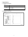
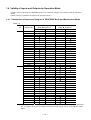
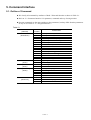
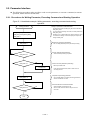
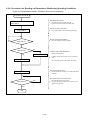
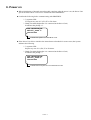
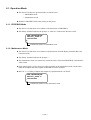
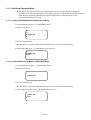
1
MEGATORQUE® MOTOR SYSTEM User’s Manual (ESB Driver Unit System) Instructions for PROFIBUS M-E099SB0C2-126 NSK Ltd. Document Number: C20126-02 Limited Warranty NSK Ltd. warrants its products to be free from defects in material and/or workmanship which NSK Ltd. is notified of in writing within, which comes first, one (1) year of shipment or 2400 total operation hours. NSK Ltd., at its option, and with transportation charges prepaid by the claimant, will repair or replace any product which has been proved to the satisfaction of NSK Ltd. to have a defect in material and/or workmanship. This warranty is the sole and exclusive remedy available, and under no circumstances shall NSK Ltd. be liable for any consequential damages, loss of profits and/or personal injury as a result of claim arising under this limited warranty. NSK Ltd. makes no other warranty express or implied, and disclaims any warranties for fitness for a particular purpose or merchantability. Copyright 2003 by NSK Ltd., Tokyo, Japan All rights reserved. No part of this publication may be reproduced in any form or by any means without permission in writing from NSK Ltd. NSK Ltd. reserves the right to make changes to any products herein to improve reliability, function or design without prior notice and without any obligation. NSK Ltd. does not assume any liability arising out of the application or use of any product described herein; neither does it convey any license under its present patent nor the rights of others. Patents issued and patents pending. “MEGATORQUE” is a registered trademark of NSK Ltd. in Japan, and that of NSK Precision America, Inc. in the United States of America. Introduction ◎ About This Manual l This manual describes the interface with PROFIBUS. Other matters related to the Megatorque Motor System, refer to the User’s Manual for ESB Driver Unit. l Please read thoroughly this manual for safety use of the Megatorque Motor System. ◎ Limited Function for ESB Driver Unit Compatible With PROFIBUS l The following functions are not available for the ESB Driver Unit compatible with PROFIBUS communication. à Velocity control and torque control mode operation. à Operation by pulse train position command. à Acceleration profiling function. (Blank Page) Contents 1. Specifications --------------------------------1-1 4.4. Output Signal---------------------------------------------4.4.1. Driver Unit Ready (DRDY) / Warning (OVER) -------------------------------4.4.2.In-Position (IPOS) --------------------------------4.4.3. Processing Pulse Generation (BUSY) ------4.4.4. Brake (BRK) ---------------------------------------4.4.5. Brake Control (BRKC) --------------------------4.4.6. Home Position Defined (HCMP) -------------4.4.7. Home Return Completed / Home Position Detected (HOME) --------4.4.8. Velocity Report (SPD) -------------------------4.4.9. Move / Channel Acknowledgement 1.1. PROFIBUS Specifications -----------------------------1-1 1.2. Dimensions of Driver Unit -----------------------------1-1 1.3. Specifications of Control Input and Output Signals ------------------------------------- 1-2 1.4. Validity of Inputs and Outputs by Operation Mode ---------------------------------------1-3 1.4.1. Combination of Inputs and Outputs in PROFIBUS Mode and Maintenance Mode -------------------------------------------------------------I-3 2. Interface Specifications ---------------------2-1 4-6 4-6 4-7 4-7 4-7 4-7 4-8 4-8 4-9 (ACK_PRGx)---------------------------------- 4-9 2.1. CN2 Connector -------------------------------------------2-1 2.1.1.CN2 Pin-Out ----------------------------------------2-1 2.1.2. Signal Code and Function ----------------------2-2 2.2. PROFIBUS-DP Interface--------------------------------2-3 2.2.1. CN5 (PROFIBUS) Pin-Out ---------------------2-3 2.2.2. SW1: Termination Resistor Switch -----------2-3 2.2.3. SW2 and Sw3: Node Address Switch --------2-3 2.2.4. Indication of STATUS LED ---------------------2-4 4.4.10. Emergency Stop State (EMSTA) -----------4-11 4.4.11. State of Over-travel Limit (OtxA) -----------4-11 4.4.12. State of Home Position Limit Sensor (HLSA) ------------------------------------------4-11 4.4.13. Target Proximity / In Target 3. Setting -----------------------------------------3-1 4.4.15.Parameter Number (PRM_GET_NO) ------4-13 4.4.16. Parameter Contents (PRM_GET_DATA) -------------------------4-13 (NEARA、NEARB) --------------------------4-12 4.4.14.Processing Confirmed / Data Processed Result (PRM_ACK/PRM_STS)-------------4-13 3.1. Termination Resistor ------------------------------------3-1 3.2. Node Address --------------------------------------------3-1 3.3. Configuration by GSD File ------------------------------3-1 5. Command Interface--------------------------5-1 5.1. Outline of Command ------------------------------------ 5-1 5.2. Parameter Interface ------------------------------------- 5-2 5.2.1. Procedures for Writing Parameter, Executing Command and Starting Operation------------ 5-2 5.2.2. Procedures for Reading out Parameters / Monitoring Operating Conditions-------------- 5-3 5.3. Program Interfface --------------------------------------- 5-4 5.3.1. Procedures for Editing Intenal Program --- 5-4 5.3.2. Procedure for Reading out Internal Program --------------------------------------------------------- 5-5 5.4. Command List--------------------------------------------- 5-6 5.4.1. Parameter------------------------------------------- 5-6 5.4.2. Managing Command ----------------------------- 5-9 5.4.3. Operation Command ----------------------------- 5-9 5.4.4. Editing Program ----------------------------------5-10 5.4.5. Program Command------------------------------5-10 5.4.6. Monitor----------------------------------------------5-11 5.4.7. Processing Decimal Place ---------------------5-15 4. Input and Output Specifications ----------4-1 4.1. Data Packets -----------------------------------------------4-1 4.2. I/O and Signal Format ----------------------------------4-1 4.3. Input Signal -------------------------------------------------4-2 4.3.1. Emergency Stop (EMST) ------------------------4-2 4.3.2. Servo ON (SVON) ---------------------------------4-2 4.3.3. Start Programmable Indexer (RUN)-----------4-2 4.3.4. Stop (STP)-------------------------------------------4-2 4.3.5. Clear Position Error Counter / Alarm (CLR) ---------------------------------------------------------4-3 4.3.6. Integration OFF / Lower Velocity Gain (IOFF) ---------------------------------------------------------4-3 4.3.7. Clamp cancel (CLCN) ----------------------------4-3 4.3.8. Home Return Start (HOS) -----------------------4-3 4.3.9. Override (ORD)-------------------------------------4-4 4.3.10. Internal Program Channel Select (PRGx: x=0 to 5) ---------------------------------4-4 4.3.11. Jog (JOG) -----------------------------------------4-4 4.3.12. Jog Direction (DIR) ------------------------------4-5 4.3.13. Write / Read Parameter, Process Type (PRM_REQ/PRM_OPE) -----------------------4-5 4.3.14. Parameter Number (PRM_SET_NO) -------4-5 4.3.15. Writing Data Type (PRM_SET_DATA)--------------------------------4-5 —i — 6. Power on----------------------------------------6-1 6.1. Operation Mode -------------------------------------------6-2 6.1.1. PROFIBUS Mode ----------------------------------6-2 6.1.2. Maintenance Mode --------------------------------6-2 6.1.3. Switching Operation Mode ----------------------6-3 6.1.3.1. Switch PROFIBUS Mode to Maintenance Mode-------------------------6-3 6.1.3.2. Switch Maintenance Mode to PROFIBUS Mode---------------------------6-3 7. Additional Function, Command and Alarm --------------------------------7-1 7.1. Additional Function --------------------------------------7-1 7.1.1. Override Function----------------------------------7-1 7.2. Additional RS-232C Command------------------------7-2 CP: Switch PROFIBUS /Maintenance Mode --7-2 IO: Input / Output Monitor ---------------------------7-3 OV: Override--------------------------------------------7-4 7.2.1. Additional Parameter List -----------------------7-5 7.3. Additional Alarm -----------------------------------------7-6 7.3.1. Fieldbus Error---------------------------------------7-6 — ii — 1. Specifications 1.1. PROFIBUS Specifications Table 1-1 Interface format Communication media Baud rate Communication distance Network size Data packets PROFIBUS-DP slave interface Special four wires twisted pair cable Automatic detection (Maximum 12 Mbps) 100 m (12 Mbps) 200 m (1500 Kbps) 400 m (1500 Kbps) 1000 m (187.5 Kbps) Up to 126 nodes Input: 10 bytes, Output: 10 bites 1.2. Dimensions of Driver Unit Table 1-1 Unit: mm — 1-1 — 1.3. Specifications of Control Input and Output Signals Table 1-2 Input signal When the operation mode is set to PROFIBUS: Emergency stop, Home position limit sensor and Over-travel limit switch (CW and CCW) CN2 When the operation mode is set to the maintenance mode: Emergency stop, Servo on, Clear, Velocity loop integration OFF /Lower velocity gain, Clamp cancel*1, Home Return start, Home position sensor, and Over-travel limit switch (CW and CCW) Control When the operation mode is set to PROFIBUS: Input Emergency stop, Servo on, Programmable Indexer start , Stop, Clear, Velocity loop integration OFF/Lower velocity gain, Clamp cancel*1, Home Return start, Override, PROFIBUS Programmable Indexer channel select, Jog, Direction Select. (CN5) *Emergency stop is the logical sum with Emergency Stop signal of CN2. All input signals are invalid in the maintenance mode. Position feedback signal CN2 Output signal Refer to “Resolution of Resolver” described in the “Megatorque Motor System User’s Manual” which is provided with the Driver Unit. Driver Unit ready, In-position, and Brake/ Brake control*1. When the operation mode is set to PROFIBUS: Driver Unit ready, Warning, In-position, Processing pulse generation, Brake/ Brake control*1, Home position defined, Home Return completed/Home position detected, Velocity report, Operation program respond, Emergency stop state, Control Over-travel limit (CW and CCW), Home position sensor, PROFIBUS Output Target proximity point A, Target proximity B. (CN5) When the operation mode is set to the maintenance: Driver Unit ready, Warning, In-position, Processing pulse generation, Brake/ Brake control*1, Home position defined, Home Return complete/Detect Home position, Velocity report, Emergency stop state, Over-travel limit (CW, CCW), Home position sensor, Target proximity A/Target proximity B. *1: When using motor with brake combined with brake sequence function(BF1), signals Integrator off / Low gain will be used as Clamp cancel input, Brake output will be used as Brake control output. l The switching command CP from the Handy Terminal specifies PROFIBUS mode or the maintenance mode. Refer to operational description of CP command for more details. l PROFIBUS mode is to operate the Driver Unit in accordance with the control input signals from PROFIBUS. l The maintenance mode is to operate tentatively the Driver Unit when PROFIBUS is not functioning for some reason. l PROFIBUS mode is set to the initial setting after the Driver Unit is turned on. — 1-2 — 1.4. Validity of Inputs and Outputs by Operation Mode Validity of Input and Output of PROFIBUS and CN2 connector changes in accordance with the operation modes. (Mode selection command CP switches the operation mode.) 1.4.1. Combination of Inputs and Outputs in PROFIBUS Mode and Maintenance Mode Table 1-3 I/O Signal code Input EMST SVON RUN STP CLR IOFF /CLCN*1 HOS ORD PRG0 PRG1 PRG2 PRG3 PRG4 PRG5 JOG DIR HLS OTP OTM DRDY OVER IPOS BUSY BRK/BRKC*1 HCMP HOME SPD ACK_PRG0 ACK_PRG1 ACK_PRG2 ACK_PRG3 ACK_PRG4 ACK_PRG5 EMSTA OTPA OTPM HLSA NEARA NEARB Output PROFIBUS mode (Valid: ü, Invalid: ×) PROFIBUS CN2 ü ü ü × – – ü ü Maintenance mode (Valid: ü, Invalid: ×) PROFIBUS CN2 × × × × × × × × × × × × × × × ü ü – – ü × × × – – – – – – – – – ― ü ― ü ― ü – – – × ü ü ü ü – ü – ü ü ü ü ü – ü – ü ü ü ü ü ü ü ü ü ü ü ü ü ü ü ü ü ü – – – – – – – – – ü ü ü ü – – ü – ü × ü – × ü – × ü – × ü – × ü – × ü – ü ü – ü ü – ü ü – ü ü – ü ü – ü ü – *1: When using motor with brake combined with brake sequence function(BF1), signals Integrator off / Low gain will be used as Clamp cancel input, Brake output will be used as Brake control output. – – – – – – – – – – – – – – – ü ü — 1-3 — ü ü (Blank Page) — 1-4 — 2. Interface Specifications 2.1. CN2 Connector 2.1.1. CN2 Pin Out Figure 2-1 25 *1 (IOFF/CLCN ) 24 (HOS) 23 OTM 22 – 21 – 20 *CHA 19 *CHB 18 CHZ 17 SGND 16 DRDY+ 15 IPOS 14 (SVON) l 13 12 11 10 9 8 7 6 5 4 3 2 1 DC24V EMST HLS (CLR) OTP – – CHA CHB *CHZ BRK/BRKC *1 DRDYCOM Signals SVON, CLR, IOFF/CLCN*1 and HOS, which are put in parentheses, are not valid in PROFIBUS mode. *1: Signals parenthesized in the above figure (SVON, CLR, IOFF/CLCN*1, and HOS) are not valid in PROFIBUS mode. — 2-1 — 2.1.2. Signal Code and Function Table 2-1 Pin No. 1 2 3 4 5 6 7 8 9 10 11 12 13 14 15 16 17 18 19 20 21 22 23 24 25 Signal code I/O COM DRDYBRK/BRKC*1 *CHZ※1 CHB CHA – – OTP (CLR) ※2 HLS EMST DC24 IPOS DRDY+ SGND CHZ※1 *CHB *CHA – – OTM (HOS) ※2 (IOFF/CLCN*3) *2 (SVON) ※2 O O O O O O – – I I I I I O O – O O O – – I I I I Function Output COMMON Driver Unit ready (–) Brake /Brake control signal (normally closed) Position feedback signal *øZ / Digital position signal *MSB*1 Position feedback signal øB Position feedback signal øA Do not connect. Do not connect. Over-travel limit (+ direction: CW) Clear input Home position limit switch Emergency stop External power supply 24 VDC In-position Driver Unit ready (+) Signal ground Position feedback signal *øZ / Digital position signal *MSB*1 Position feedback signal øB Position feedback signal øA Do not connect. Do not connect. Over-travel limit (- direction: CCW) Home Return start Integrator OFF /Clamp cansel Servo ON *1: Parameter FZ (RS-232C communication) sets function of “Position feedback signal *øZ” and “Digital position signal *MSB.” *2: Signals parenthesized in the above table (SVON, CLR, IOFF, and HOS) are not valid in PROFIBUS mode. *3: When using motor with brake combined with brake sequence function(BF1), signals Integrator off / Low gain will be used as Clamp cancel input, Brake output will be used as Brake control output. — 2-2 — 2.2. PROFIBUS-DP Interface Figure 2-2 - RxD/TxD- - (Vcc) ⑨ ⑧ ⑦ ⑥ ⑤ ④ ③ ② ① PROFIBUS-DP Interface GND - Termination resistor switch RxD/TxD+ - Node address switch 1 - Node address switch 2 PROFIBUS CN5 SW1 SW2 SW3 STATUS LED 2.2.1. CN5 (PROFIBUS) Pin-Out Table 2-2 Pin 1 2 3 4 5 6 7 8 9 Signal code - - RxD/TxD+ - GND (Vcc) - RxD/TxD– - I/O ----Input/Output --------Input/Output --- Function Do not connect. Do not connect. Signal (+) Do not connect. Ground +5 VDC (For PROFIBUS) Do not connect. Signal (–) Do not connect. l Voltage supply (Pin number 6) is for the external termination of network, which must be provided at the both ends of PROFIBUS. Refer to the specifications of PROFIBUS for the details of cable termination. 2.2.2. SW1: Termination Resistor Switch Table 2-3 Switch setting Termination resistor switch ON Termination resistor switch OFF Function Termination resistor is effective. Termination resistor is ineffective. 2.2.3. SW2 and SW3: Node Address Switch l These switches are for setting node address in the range of 1 to 99. The switch SW1 sets the number of tens, while the SW2 switch sets the number of ones. — 2-3 — 2.2.4. Indication of STATUS LED Figure 2-3 Idle Fieldbus diagnostic Off line On line Table 2-4 Name Diagnostic of fieldbus Color Red Off-line On-line Red Green Function Indicates failure of the fieldbus. Blinking frequency identifies the details of failure. · Blinking at 1 Hz. An input or output configuration is not in the specified packet length (10 byte). · Blinking in 2 Hz There is an error on the user parameter. · Blinking in 4 Hz A problem has occurred at the moment of initialization of the PROFIBUS communication LSI. Internal network module is off-line. Internal network module is on-line: thus enables communication. — 2-4 — 3. Setting l You need to set the following to operate the Driver Unit in your network. à Termination resistor à Node address à Configuration by GSD file l The Driver Unit automatically detects and sets the communication speed. The Driver Unit supports the baud rates listed in the table below. Table 3-1 Supporting baud rate 9.6 Kbit/s 19.2 Kbit/s 45.45 Kbit/s 93.75 Kbit/s 187.5 Kbit/s 500 Kbit/s 1.5 Mbit/s 3 Mbit/s 6 Mbit/s 12 Mbit/s 3.1. Termination Resistor l When the Driver Unit is set to the top or the end of PROFIBUS network, set the termination resistor switch to ON. If you an external termination resistor, set the termination resistor switch to OFF. 3.2. Node Address l Two rotary switches, SW2 and SW3, set the node address. Settable range of node address is 1 to 99. SW2 sets the number of tens and SW3 sets the number of ones. Thus, the relation between the node address and the settings of SW2 and SW3 switches can be numerically expressed as follows. Node address = (Setting of SW2 × 10) + (Setting of SW3 × 1) 3.3. Configuration by GSD File l A GSD file can be downloaded from web page of NSK. — 3-1 — (Blank Page) — 3-2 — 4. Input and Output Specifications 4.1. Data Packets Input Output : 10 bytes : 10 bytes 4.2. I/O and Signal Format Table4-1 Byte 0 Input (Master controller ® Driver Unit) Bit Function 0 EMST (Emergency stop) 1 SVON (Servo ON) 2 RUN (Start Programmable Indexer) 3 STP (Decelerates to stop) 4 Byte 0 CLR (Clear) *1 5 1 2 3 4 5 6 7 8 9 6 7 0 1 2 3 4 5 6 7 0 1 2 3 4 5 6 7 0 1 2 3 4 5 6 7 – – – – – – IOFF /CLCN (Integration OFF /Clamp cansel) HOS (Home Return start) ORD (Override) PRG0 (Program channel 0) PRG1 (Program channel 1) PRG2 (Program channel 2) PRG3 (Program channel 3) PRG4 (Program channel 4) PRG5 (Program channel 5) (Reserved) (Reserved) JOG (Jog start) DIR (Jog direction) (Reserved) (Reserved) (Reserved) (Reserved) (Reserved) (Reserved) (Reserved) (Reserved) (Reserved) (Reserved) (Reserved) (Reserved) PRM_REQ (Write/ read parameters) PRM_OPE (Write/read selection) PRM_SET_NO (Para. No.) (LSB) PRM_SET_NO (MSB) PRM_SET_DATA (Data) (LSB) PRM_SET_DATA PRM_SET_DATA PRM_SET_DATA (MSB) 1 2 3 4 5 6 7 8 9 Output (Driver Unit ® Master controller) Bit Function 0 DRDY (Driver Unit ready) 1 OVER (Warning) 2 IPOS (In position) 3 BUSY (Processing generated pulses) *1 BRK /BRKC 4 (Brake /Brake control signal) 5 HCMP (Home position defined) 6 7 0 1 2 3 4 5 6 7 0 1 2 3 4 5 6 7 0 1 2 3 4 5 6 7 – – – – – – HOME (Home Return completed) SPD (Velocity threshold) ACK_PRG0 (Move/ Program channel 0) ACK_PRG1 (Move/ Program channel 1) ACK_PRG2 (Move/ Program channel 2) ACK_PRG3 (Move/ Program channel 3) ACK_PRG4 (Move/ Program channel 4) ACK_PRG5 (Move/ Program channel 5) (Reserved) (Reserved) EMSTA (Emergency stop state) OTPA (+ Over-travel limit state) OTMA (- Over-travel limit state) HLSA (Home position limit state) NEARA (Target proximity/ In Target A) NEARB (Target proximity/ In Target B) (Reserved) (Reserved) (Reserved) (Reserved) (Reserved) (Reserved) (Reserved) (Reserved) PRM_ACK (Processing confirmed) PRM_STS (Data processed result) PRM_GET_NO (Para. NO.) (LSB) PRM_GET_NO (MSB) PRM_GET_DATA (Data) (LSB) PRM_GET_DATA PRM_GET_DATA PRM_GET_DATA (MSB) *1 : When using motor with brake combined with brake sequence function(BF1), signals Integrator off / Low gain will be used as Clamp cancel input, Brake output will be used as Brake control output. — 4-1 — 4.3. Input Signal 4.3.1. Emergency Stop (EMST) l The Driver Unit detects the input by its signal current level. l The System disables the function of position loop control when the input of EMST is set to 1, and then the Motor stops in the state of servo lock in the velocity loop control. l EMST input of CN2 connector is valid in PROFIBUS mode. Table 4-2 EMST 0 1 Function Clear Emergency Stop. Emergency Stop 4.3.2. Servo ON (SVON) l The input puts the Motor in Servo ON state. l The Driver Unit detects the input by its current level. l The Motor gets in Servo ON state when DRDY output is set to 1 after the power is on, then SVON input is set to 1. Table 4-3 SVON 0 1 Function Servo OFF Servo ON 4.3.3. Start Programmable Indexer (RUN) l This is to start a programmed operation of the specified channel in PRG0 - PRG5. l The Driver Unit detects the rising edge(0 ® 1) of input signal current. 4.3.4. Stop (STP) l The Driver Unit detects the input by its current level. l The Driver Unit stops the Motor when STP input is set to 1, and then disables the starting commands. You may set parameter MD for deceleration rate to stop the Motor. Table 4-4 STP 0 1 Function Starting commands valid. Disables the starting commands. — 4-2 — 4.3.5. Clear Position Error Counter / Alarm (CLR) l The Driver Unit detects the input by the rising edge of signal current. l The error counter is cleared when CLR input is set to 1. However, the error counter won’t be cleared when the Motor is in the middle of operation caused by the following command. à Operation by positioning commands (AD, AR, ID, IR and HS) à Operation of Programmable Indexer (AD, AR, ID, IR, HS, JP and TI) à Home Return à Jog l When the alarm of “Excessive position error” (F1) is reported, setting CLR input to 1 clears the error counter and the alarm. l Alarms of “Software thermal (A3),” “Velocity error over (A4),” “Program error (A5),” “RS-232C error (C2),” and “Automatic tuning error (F8)” will be cleared when CLR input is set to 1. 4.3.6. Integration OFF / Lower Velocity Gain (IOFF) *When brake sequence function is invalid l The Driver Unit detects the current level of input signal. l When IOFF input is set to 1, the integration control is disabled, and the parameter VG for velocity loop proportional gain is lowered with the ratio set by the parameter LG for lowering velocity gain. l Parameter IM: When IOFF input is set to 1, parameter IM sets only one function to IOFF input such as “Integration OFF,” or “Lowering velocity loop proportional gain.” l Lowering velocity gain is mainly used to control torque output when the Motor is holding its position with a brake. Table 4-5 IOFF 0 1 Function Integration ON• Lowering gain not available. IM0: Integration OFF and Lowering gain (Shipping set) IM1: Integration OFF IM2: Lower velocity gain 4.3.7. Clamp cancel Input (CLCN) *When brake sequence function is valid l Select brake clamp function valid or invalid. l If CLCN input is 1, brake will be released, and no further brake clamp will be performed. However, if an alarm (which will make motor condition servo-off) occurs, brake will clamp. l If CLCN input is 0, brake will clamp/unclamp depending on the motor motion command. Table 4-6 CLCN 0 1 Function Brake clamp function valid Clamp cancel — 4-3 — 4.3.8. Home Return Start (HOS) l The input starts Home Return. l The Driver Unit detects the rising edge(0 ® 1) of signal current. 4.3.9. Override (ORD) l The Driver Unit detects the current level of input signal. l When ORD input is set to 1, the Motor operates under the velocity, which is obtained by application of parameter CV to the velocity set by parameters MV, HV, CV or JV. l Normally ORD is set to 0. (Positioning velocity will follow the parameters MV, HV, CV and JV respectively.) l Input of OVD in the middle of positioning will be invalidated. Table 4-7 ORD 0 1 Function Override OFF Override ON 4.3.10. Internal Program Channel Select (PRGx: x = 0 to 5) l This is to specify a number of internal program channels to be executed by RUN input. l The channel number is specified by the binary codes of PRG0 to PRG5. Table 4-8 CH No. 0 1 2 3 • 61 62 63 PRG5 0 0 0 0 PRG4 0 0 0 0 PRG3 0 0 0 0 PRG2 0 0 0 0 PRG4 0 0 1 1 PRG0 0 1 0 1 • • • • • • 1 1 1 1 1 1 1 1 1 1 1 1 0 1 1 1 0 1 4.3.11. JOG l Starts and stops Jog operation. l The Driver Unit detects the rising edge of input signal current. Table 4-9 JOG (0 ® 1) ¯ (1 ® 0) Function JOG start (Starts and accelerates) JOG stop (decelerates and stops) — 4-4 — 4.3.12. Direction (DIR) l This input specifies the direction of operation. l When the input is changed in the middle of Jogging, the Motor decelerates, and then reverses the rotational direction. Table 4-10 DIR 0 1 Function CW CCW 4.3.13. Write/Read Parameter, Process Type (PRM_REQ/PRM_OPE) l This input is to process (write or read out) parameters as specified by PRM_OPE input. l The Driver Unit detects the rising edge of PRM_REQ input signal current. Table 4-11 PRM_REQ 0 0 0 ®1 (Rising edge detection) 0 ®1 (Rising edge detection) PRM_OPE 0 1 Function No request No request 0 Read out parameter settings 1 Copy parameter settings 4.3.14. Parameter Number (PRM_SET_NO) l Specifies the parameter number that is an object of writing or reading out. l Set the lower byte of parameter number to byte 4, and the higher one to byte 5. l The parameter number shall be specified by a signed integer. 4.3.15. Writing Data Type (PRM_SET_DATA) l This input specifies the type of parameter data, when requesting to write parameters. l This input can be used as a parameter for an execution of command, or a start command of operation. l Set the lowest byte of changed parameter data to byte 6, and the highest one to byte 9. l A signed integer will specify a change of parameter data. — 4-5 — 4.4. Output Signal 4.4.1. Driver Unit Ready (DRDY) / Warning (OVER) l DRDY output is 1 (one) if the Driver Unit is ready to operate the Motor. l State of DRDY / OVER outputs are shown in Table 4-12 when an alarm has been reported. Table 4-12 Alarm Setting *1 Memory error EEPROM error *2 System error Interface error Brake-on position error Excess position error Software over travel limit Hardware over travel limit Emergency stop Program error Automatic tuning error RS-232C error CPU error *2 Field bus error Resolver circuit error Absolute position error Software thermal sensor Velocity error over (serious) Velocity error over (minor) Home position undefined Brake error Heat sink overheat Abnormal main AC line voltage Over current Control AC line under voltage – – – – – EP1 EP2 EP3 TO1 TO2 HT0 HT1 HT2 – PE0 PE1 AE0 AE2 SE0 SE1 SE2 – – – – – 7-seg DRDY OVER BRK LED Output Output Output E0 0 0 0 E2 0 0 0 E7 – – – E8 0 0 0 F0 0 0 0 0 0 F1 1 1 1 0 1 0 0 F2 1 1 1 1 0 F3 1 0 0 1 1 F4 1 0 0 1 0 F5 1 1 1 1 0 F8 1 1 1 1 0 C2 1 0 0 1 1 C3 0 0 0 C4 0 0 0 A0 0 0 0 A1 0 0 0 A3 0 0 0 Motor state Readout with TA command Servo-off Servo-off Servo-off Servo-off Servo- lock E0>Memory Error Servo-lock F1>Excess Position Error Servo-lock F2>Software Over Travel Servo-lock F3>Hardware Over Travel Servo-lock F4>Emergency Stop Servo-lock F5>Program Error Normal Normal Servo-lock Normal Servo-off Servo-off Servo-off Servo-off Servo-off E2>EEPROM Error E7>System Error E8>I/F Error F0>Clamp Position Error F8>AT Error C2>RS232C Error (Cannot read out by TA) C4>Field bus Error A0>Resolver Circuit Error A1>Absolute Position Error A3>Overload 0 1 0 Servo-off 1 1 1 Servo-lock 0 1 1 0 1 Normal A8 P0 1 1 1 0 0 0 Servo- lock Servo-off P1 0 0 0 Servo-off P1>Main AC Line Trouble – P2 0 0 0 Servo-off P2>Over Current – P3 0 0 0 Servo-off P3>Control AC Line Under Voltage – OU0 OU2 – – – A4 A5 A4>Velocity Abnormal A5>Origin Undefined A8>Brake Error P0>Over Heat *1. When this alarm occurred at the time of power-on, it won’t be reported through PROFIBUS. *2. This alarm won’t be reported through PROFIBUS. — 4-6 — 4.4.2. In-Position (IPOS) l The following parameters are the conditions to output In-position signal. FW : Fin Width (Sets the time length to keep outputting IPOS signal.) IN : Criterion to detect completion of positioning. IS : In-position stability timer (Sets time length for position error stability.) 4.4.3. Processing Pulse Generation (BUSY) l This output notifies that the System is processing internal pulse train. The signal outputs 1 when executing following motion commands. à Operation by a positioning command (AD, AR, ID, IR and HS) à Programmable Indexer (AD, AR, ID, IR, HS, JP and TI) à Home Return à Jog l This output does not change by overshooting of undershooting. Table 4-13 BUSY 0 1 Function No generation of internal pulses Processing internally generated pulse 4.4.4. Brake Output (BRK) *When brake sequence function is invalid l This specifies the timing to activate optional brake when the servo is off or EMST signal is inputted. Table 4-14 BRK 0 1 Function Clamp Unclamp 4.4.5. Brake Control Output (BRKC) *When brake sequence function is valid l Brake control signal to control brake clamp / un-clamp by the driver unit. If BRKC output is 0, brake will clam. IF BRKC output is 1, brake will un-clamp. — 4-7 — 4.4.6. Home Position Defined (HCMP) l This is to notify that the Home position is set. When the power is on, HCMP output will be 1 simultaneously with DRDY output. l HCMP output will be 0 when Home Return is interrupted in the middle of operation, or parameter DI (Direction inversion) setting is changed, even though the Home position has been set. Table 4-15 HCMP 0 1 Function Home position not set. Home position is set. 4.4.7. Home Return Completed / Home Position Detected (HOME) l This is to report completion of Home Return or the Motor is on the Home position. l The following parameters set the way of report. Figure 4-1: Parameters related to HOME output HW=0 Home Return mode HOME output HW≠0 Home positoin mode Set a holding time of output to paramemter HW. Set Home position range to parameter HI. Table 4-16: Home Return mode (HW = 0) HOME 0 1 Function Home Return is not completed, or the Motor has moved from the Home position after completion of Home Return. Home return is completed, and the Motor is on the Home position. Table 4-17: HOME position mode (HW ¹ 0) HOME 0 1 Function Home position is not detected. Home position is detected. — 4-8 — 4.4.8. Velocity Report (SPD) l This is to report the Motor velocity. l The following parameters set the way of report and threshold to output signal. Table 4-18: Parameters related to SPD output Parameter SO SB ST Function Sets velocity-detecting mode. Threshold to output SPD signal Sets stability timer to output SPD signal Table 4-19: SPD Zero speed mode (SO0) SPD 0 1 Function Over the set speed Under the set speed Table 4-20: SPD Over peed mode (SO1) SPD 0 1 Function Under the set speed Over or equal to the set speed 4.4.9. Move / Channel Acknowledge (ACK_PRG ×) l Outputs the state of input for switching internal program channel before input of RUN command. l Outputs a specified channel number while generating internal pulses after input of RUN command. l In case of ‘&’ sequence, this signal outputs the specified channel number after input of RUN command. l A binary number of ACK_PRG0 to ACK_PRG5 (6 bits) specifies the channel numbers. Table 4-21: CH No. 0 1 2 3 • 61 62 63 ACK_PRG5 0 0 0 0 ACK_PRG4 0 0 0 0 ACK_PRG3 0 0 0 0 ACK_PRG2 0 0 0 0 ACK_PRG1 0 0 1 1 ACK_PRG0 0 1 0 1 • • • • • • 1 1 1 1 1 1 1 1 1 1 1 1 0 1 1 1 0 1 — 4-9 — Figure 4-2: Signal timing of program operation (An example shown below is to start the channel number 5.) Channel select PRG0 Input ON OFF PRG1 Input ON OFF PRG2 Input ON OFF PRG3 Input ON OFF RUN Input ON OFF Motor motion ON OFF BUSY Output ON OFF Channel acknowledge ACK_PRG0 Output ON OFF ACK_PRG1 Output ON OFF ACK_PRG2 Output ON OFF ACK_PRG3 Output ON OFF Start Velocity in CW/CCW In motion Outputs specified channel. Outputs state of PRG0 input. Outputs state of PG0 input. Affedted by external force IN setting Error counter residual pulses IPOS Output IPOS mode (FW=0) closed open IPOS Output CFIN mode (FW>0) closed open IPOS Output FIN mode (FW>0) closed open FW setting Example) FW1:100 ms — 4-10 — 4.4.10. Emergency Stop State (EMSTA) l This is to inform the state of Emergency stop. l This output is a logic sum of EMST of CN2 control input and PROFIBUS control input. Table 4-22: EMSTA 0 1 Function Clear emergency stop Emergency stop 4.4.11. State of Over- travel Limit (OtxA) l This output reports the state of over-travel limits. l This output is a logic sum of OTx of CN2 control input and software over-travel limit. Table 4-23: OTxA 0 1 Function Travel limit is not detected. Travel limit is detected. 4.4.12. State of Home Position Limit Sensor (HLSA) l This output reports state of Home position limit sensor (HLS of CN2 control input). Table 4-24: HLSA 0 1 Function Home position sensor is not detected. Home position sensor is detected. — 4-11 — 4.4.13. Target Proximity / In Target (NEARA, NEARB) l This output reports that the Motor is nearing the target position, or the Motor is in a specified target zone. l The following parameters set the type of report. l Refer to “7.1.14. Target Proximity / In Target” of ESB User’s Manual. Figure 4-3: Related parameters to NEAR output NMA = 0 NEARA Output Target proximity mode NMA ¹ 0 In target mode NMB = 0 NEARB Output Target proximity mode Sets distance from the target to parameter NA for outputting Target proximity signal. Sets signal holding time to parameter NMA. Sets outputting pointion to parameter ZAS. Sets position to terminate outputting to parameter ZAE. Sets distance to output Target proximity siganl to parameter NB. Sets signal holding time to parameter NMB. Sets outputting pointion to parameter ZAS. Sets position to end outputting to parameter ZAE. NMB ¹ 0 In target mode Table 4-25: NEARx: Target proximity (NMx = 0) NEARx 0 1 Function Not nearing target position. Nearing target position. Table 4-26: NEARx: In Target (NMx ¹ 0) NEARx 0 1 Function Not in target zone. In target zone. — 4-12 — 4.4.14. Processing Confirmed / Data Processed Result (PRM_ACK / PRM_STS) l This output reports the end of processing and the processed result as the response to the commands of Write / Read parameters. l PRM_ACK reports completion or incompletion of parameter processing, while PRM_STS reports the result of the processing (success/fail). Table 4-27: PRM_ACK 0 0 1 1 PRM_STS 0 1 0 1 Function Idle or processing data as instructed. Idle or processing data as instructed. Processing completed (Failed) Processing completed (Successful) 4.4.15. Parameter Number (PRM_GET_NO) l This is to report the parameter number that is the objective for reading out or writing data. l The lower byte of the parameter number shall be set to byte 4, and the higher one to byte 5. l A signed integer will report a parameter number. 4.4.16. Parameter Contents(PRM_GET_DATA) l When reading out parameters is requested, this signal outputs the contents of read-out parameter. l When reading out of parameter is requested, this signal outputs copies of PRM_SET_DATA. l Set byte 6 to the lowest byte of the parameter contents, and byte 9 to the highest byte. l The contents of parameter will be reported in a signed integer. — 4-13 — (Blank Page) — 4-14 — 5. Command Interface 5.1. Outline of Command l We classify all commands by attribute of Read / Write and function as shown in Table 5-1. l Refer to “5.2. Parameter Interface” for parameter, command and way of using monitor. l Program commands are the same attribute as the parameters, but they differ from the parameters in way of use. Refer to “5.3. Program Interface.” Table 5-1 Command (attribute) Parameter (Read/Write) Command (Write) Operation (Write) Program editing (Write) Monitor (Read out) Command number 001 – 019 020 – 039 040 – 059 060 – 079 080 – 099 100 – 119 120 – 139 140 – 159 160 – 179 180 – 199 200 – 219 220 – 239 240 – 259 260 – 279 280 – 299 300 – 319 320 – 339 400 – 419 420 – 439 500 – 519 600 – 619 620 – 639 640 – 659 660 – 679 800 – 819 820 – 839 840 – 859 Classification Servo parameters (1) Servo parameters (2) Related to servo state output Related to pulse train input operation Related to position feedback signal Related to position scale Related to velocity Related to Home Return Characteristic of Motor Related to I/O Related to processing parameter Related to automatic tuning Special functions Related to outputs for expanded function Related to warning Adjusting Processing parameter Positioning Home Return Editing internal program Positioning Home Return Control command Optional code Alarm Read out internal program Various monitors — 5-1 — 5.2. Parameter Interface l The following procedures make possible to read or write parameters, to execute a command, to start an operation, and to monitor current status. 5.2.1. Procedures for Writing Parameter, Executing Command and Starting Operation Figure 5-1: Handshake example: Writing parameter, executing command and starting operation Setting of parameter number/write data Writing procedure Set parameter number to PRM_SET_NO, and set its data to PRM_SET_DATA. For commands and starting commands, set their paramters to PRM_SET_DATA. Whether to use or disuse PRM_SET_DATA, it differs in some commands and starting commands. Specify the request for writing to PRM_OPE. PRM_SET_NO=[Parameter number] PRM_SET_DATA=[Setting data] PRM_OPE=1 Request for processing parameters. PRM_REQ =1 No Set 1 to PRM_REQ to request for parmeter processing. Wait for “Data Processed Result.” Wait untill data processing completes. PRM_ACK =1? Yes PRM_STS =1? No Confirm result of parameter processing. Get the processed result. Yes Correct error. If the writing parameters fails, take an action for error according to need. Complete of processing paramete. PRM_REQ = 0 Set 0 to PRM_REQ to complete processing parameters after the confirmation of result. Wait until the Driver Unit becomes idle. PRM_ACK= 0? No Wait until PRM_ACK changes to idle. When it is idle, the Driver Unit is ready for the next command. Yes End — 5-2 — 5.2.2. Procedures for Reading out Parameters / Monitoring Operating Conditions Figure 5-2: Handshake example: Parameter read out and monitoring Procedure to read out Set parameter number. PRM_SET_NO=[Parameter Nunber] Set parameter number to PRM_SET_NO. Specify the request of reading out to PRM_OPE. PRM_OPE=0 Request to process parameters. PRM_REQ=1 No Set 1 to PRM_REQ to execute parameter processing. Wait for “Data Processed Result.” Wait until the data processing completes. PRM_ACK=1? Yes PRM_STS=1? No Confirm result of data processing. Yes correct error. Get the processed result. If reading out fials, take an action for error according to need. Get PRM_GET_DATA. If it is successful, get the esult by PRM_GET_DATA. End of parameter procssing. PRM_REQ =0 After the confirmation of result, set 0 to PRM_REQ for the completion. Wait until the Driver Unit becomes idle. PRM_ACK=0? No Wait until PRM_ACK changes to idle. When it is indicating that the Driver Unit is idle, you may input the next command. Yes End — 5-3 — 5.3. Program Interface l Use of the program interface enables to edit and read out the internal programs. The program interface consists of a number of command interfaces. 5.3.1. Procedure for Editing Internal Program Figure 5-3: Handshake example: Editing internal program Start of editing internal porogram. Edit internal program. Execute command number 500 in accordance with the procedures for writing parameter. The System gets in the internal program editing mode when the command 500 is executed. The System only accepts programming command and optional codes until an entry of termination command for edting and reading out program (command number 502). Execute command number 500. (Start to edit intarnal program.) Execute any one of command numbers 600 to 611, 620, 640, and 641. (Program command) Set progam command. Execute any one of the program command numders 600 to 611, 620, 640, or 641 in accordance with the procedures for writing parameter. Execute any one of command numbers 660 to 663. Set optional code. Setting of opetional code If it is necessary, set any one of optional codes 660 to 663 for the specified program command in accordance with the procedures for writing parameter. Yes No Execute command number 502. (End of editing and reading out internal program) End of editing internal program. Execute command number 502 in accodnace with the procedures for writing parameter. Execution of the command number 502 terminates the mode to edit internal program of the specified cahnnel. End l The table below shows the combinations of available program commands and optional codes. Table 5-2: Combination of program commands and optional codes Optional code Command 600 (AD), 601 (AD/PL), 602 (AD/MI), 603 (AD / EX) 660 – 661 OE n 662 CV n 663 CA n N/A 604 (AR), 605 (AR/PL), 606 (AR/MI), 607(AR/EX) N/A P P P P P P P P P P P P P N/A N/A N/A N/A N/A N/A N/A N/A 608 (ID), 609 (ID/EX) P 610 (IR), 611 (IR/EX) P N/A N/A N/A 620 (HS) 640 (JP) 641 (TI) — 5-4 — 5.3.2. Procedure for Reading out Internal Program Figure 5-4: Example of handshake: Reading out internal parameter Start reading out of internal program. Read out a program Execute command number 501 in accordance with the procedures for writing parameter. The System gets in the mode to read out an internal program of the specified cahnnel by the execution of command number 501. The System only accepts the command to read out internal program until the execution command to terminate editing and reading out internal program (command number 502). Execute command number 501. (Starting of reading out internal program) Execute command number 820. (Read out internal progrma.) PRM_GET_NO= -1 Read out internal program. Execute program command nember 820 in accodance with the procedures for reading put parameter. Yes No Getting command / optional code When acquired PRM_GET_NO is other than – 1, it indicates command/optional code. PRM_GET_DATA is a data set to the acquired command/optional code. Get command/optional code. PRM_GET_DATA When acquired PRM_GET_NO is – 1, it indicates that all contents in the specifeid channel are read out. No Interrupt reading out. Yes Execute the command for termination of editing and Execute command number 502. reading out of internal program. (End of editing/read out internal program.) Execute command number 502 in accordance with the procedures for writing parameter. Execution of command number 502 will cancel the mode to read out an internal program of the specified cahnnel. End. — 5-5 — 5.4. Command List l The parameters marked with « of the column of “Correspondence” in the lists below require to lift the protection by inputting “/NSK ON” when setting them via RS-232C. It does not require lifting the protection for setting them through PROFIBUS. l Refer to “5.4.7. Processing Decimal Place” for the decimal place in the command lists. 5.4.1. Parameter Table 5-3: Parameter List Initial setting Data range Unit Decimal place 0.100 1.0 1.0 1.00 0.010 – 1.000 0.1 – 255.0 0.1 – 255.0 0.10 – 63.00 – – – Hz 3 1 1 2 1.00 0.10 – 63.00 Hz 2 – 0 % % 0 0 pulse 0 ms – 0 – s-1 2 Hz 0 Parameter Correspondence 1 2 3 4 PG VG VGL VI 5 VIL 6 «VM Velocity integrator mode 7 8 LG «TL Lower gain Torque limit rate 9 «GP Gain switching point 0 10 11–19 GT – Switching gain timer Reserved 5 – 20 FO Low-pass filter, off velocity 21 FP Low-pass filter, primary 0 22 FS Low-pass filter, secondary 0 23 NP Notch filter, primary 0 24 NS Notch filter, secondary 0 25 26 27 28 29 30–39 NQ «DBP «ILV «FF «FC - 40 CO 41 42 IN IS Notch filter, Q parameter Dead band Integration limit Feed forward gain Friction (Reserved) Position error counter over limit In-position In-position stability counter 43 FW In-position FIN width 44 «VO Velocity error over limit 45 46 47– 49 50 51– 61 «VW «OR - «CE - Velocity error over limit width 62 «RR 63–79 – Function Position gain Velocity gain Velocity gain, lower Velocity integrator frequency Velocity integrator gain, lower 0.25 0 100.0 0.0000 0 – 0: No integration 1: Integration available 0 – 100 0 – 100 0:No gain switching 1 – 1 000 0 – 1 000 – 0: Switching off 0.01 – 3.00 0: Filter OFF 10 – 500 0: Filter OFF 10 – 500 0: Filter OFF 10 – 500 0: Filter OFF 10 – 500 0.10 – 5.00 0 – 4095 0.0 – 100.0 0.0000 – 1.0000 0 – 2047 – Hz Hz pulse % – – – 2 0 1 4 0 – 50 000 1 – 99 999 999 pulse 0 1 50 100 0.00 100 0.0 1.0 Criterion, overrun alarm Reserved Brake-on position error Reserved Hz Hz 0 – 99 999 999 pulse 0, 0.3 – 100.0 100 ms 0.0: COIN mode - + 0.3– +100.0:FIN mode 100 ms - 0.3– –100.0:CFIN -100 ms mode 0 0 0 0 1 1 2730 1 – 5461 3.000/ -1 5461 s 0 100 409 600 0 – 1 000 204 800 – 819 200 ms pulse 0 0 – – – – 1000 1 – 99 999 999 pulse 0 – – – – Resolver resolution –3 -3: High/low switching 1:Fixed to low resolution – 0 (Reserved) – – – – — 5-6 — Table 5-4: Parameter list (Continued [1]) Parameter Correspondence 80 FD 81 «FZ 82 «FR 83 – 99 100 Initial setting Function Data range 0: Leading phase A in CW. 1: Leading phase B in CW. 0: øZ output 1: MSB output Unit Decimal place – 0 – 0 1 1: 12bit resolution – 0 – «PS Position feedback signal phase. Position feedback signal Z/MSB Resolution: Position feedback signal (Reserved) Position scale select – 1 – rev – 0 101 «DI Direction inversion 0 – 0 102 103 «OTP «OTM 0 0 pulse pulse 0 0 104 «AO 0 0 – 819 199 pulse 0 105–119 120 121 122 123 124 125 126 – MV MA JV JA HV HA HZ Over travel limit position Over travel limit position Absolute position scale offset (Reserved) Move velocity Move acceleration JOG velocity JOG acceleration Home return velocity Home return acceleration Home return near-zero speed – 1 0: CW is (+). 1: CCW is (–). 0 – ± 99 999 999 0 – ± 99 999 999 – s-1 s-2 s-1 s-2 s-1 s-2 s-1 – 4 2 4 2 4 2 4 127 MD Move deceleration s-2 2 128–130 131 132–139 – OV – (Reserved) Velocity change ration (Reserved) - % – – 0 – 140 «OS Origin setting mode 4 – 0 141 «PH Program Home Return 0 – 0 142 «HD Home Return direction 1 – 0 143 144–159 160 161 162 «HO - «PA «OL «RC Home offset (Reserved) Phase adjust Overload limit *1 Rated current 0 – 700 – – pulse – – – % 0 – 0 0 0 163 «LR Low torque ripple 0 – 0 164 «RO – 0 165–179 180 181 – «AB «NW ABS/INC resolver set position offset (Reserved) I/O polarity Chattering preventive timer – – 2.8 ms – 0 0 182 «IM IOFF mode 0 – 0 183–189 190 191 192 193–199 – «BF «WC «WU – (Reserved) Brake sequence function Brake-on timer Brake-off timer (Reserved) – 0 *1 *1 – – – 100 ms 100 ms – – 0 0 0 – 0 0 – 1.0000 1.00 0.1000 1.00 0.2000 1.00 0.0100 0 – 100 – 2 048 – 00h 0 *1: Initial setting differs with Motor size. — 5-7 — – 0.0001 – 3.0000 0.01 – 1 280.00 0.0001 – 3.0000 0.01 – 1 280.00 0.0001 – 3.0000 0.01 – 1 280.00 0.0001 – 0.2000 0: Stop immediately. 0.01 – 1 280.00 – 0 – 200 – 1, 3, 4, 5: Standard homing. 6: Home position by teaching 0: Automatic homing invalid 1: Each programmed operation (when Home position is not set.) 2: Each RUN input. 0: (+) direction 1: (–) direction 0 – ± 802 816 - 24 – 1 048 0 –100 0 –100 0: Standard 1: Low torque ripple 0 – 4 095 – 0000 0000b – 0101 0011b 0–4 0: Integration OFF and lower gain. 1: Integration OFF 2: Lower gain - 0, 1 *1 – 30.0 *1 – 30.0 - Table 5-5: Parameter List (Continued [2]) Parameter Correspondence Initial setting 200 «WM Write mode to EEPROM 0 201–219 220 221 222–239 – «LO SG – (Reserved) Load inertia Servo gain (Reserved) – 0 0 – 240 «SL Control mode 3 241 AL Acceleration limiter 0 242–259 260 261 – HW HI (Reserved) Home signal holding time Home In-position 262 «SO SPD output mode Function – 0.0 0 0 263 264 SB ST 265 «NMA 266 «NMB 267 268 269 270 271 272 273–279 NA NB ZAS ZAE ZBS ZBE - Criterion, SPD signal output Speed stability timer Near A/Near position A output mode Near B/Near position B output mode Near position A Near position B Start point of zone A Endpoint of zone A Start point of zone B Endpoint of zone B (Reserved) 280 «OU Origin Undefined 0 281 «EP Excessive position error , Alarm type 2 282 «TO Software travel limit over, Alarm type 2 283 «HT Hardware travel limit over, Alarm type 2 284 «PE Program error, Alarm type 2 285 «AE Automatic tuning error, Alarm type 2 286–299 – (Reserved) – — 5-8 — 0.00 0.0 0.0 0.0 100 100 0 0 0 0 – Data range 0: Backup 1: No backup – 0.000 – 50.000 0 – 30 – 1: Torque control 2: Velocity control 3: Position control 0: Function disabled. 0.01 – 1 280.00 – 0, 0.3 – 100.0 0 – 102 400 0: Zero speed mode 1: Over speed mode 0.00 – 3.00 0, 0.3 – 100.0 0.0: Proximity mode 0.3 – 100.0: Area mode 0.0: Proximity mode. 0.3 – 100.0: Area mode 1 –99 999 999 1 – 99 999 999 0 – ± 99 999 999 0 – ±99 999 999 0 – ±99 999 999 0 – ±99 999 999 – 0: DRDY/OVER No change 2: OVER output closed 1: DRDY output open. 2:OVER output closed. 3:DRDY: Open OVER: Closed 1:DRD: open 2:OVER: closed 0:DRDY/OVER No change. 1: DRDY: Open 2: OVER: Closed 0: DRDY/OVER No change 2: OVER: Closed 0:DRDY/OVER No change 2:OVER: Closed – Unit Decimal place – 0 – kgm2 Hz – – 3 0 – – 0 s-2 – 100 ms pulse 2 – 1 0 – 0 -1 2 1 s 100 ms – 100 ms – 100 ms pulse pulse pulse pulse pulse pulse – 0 0 0 0 0 0 – – 0 – 0 – 0 – 0 – 0 – 0 – – 1 1 5.4.2. Managing Command Table 5-6 Command 300 301 302 303 –319 Correspondence AZ AT «OG – 320 «SI 321 322– 329 330 331– 339 «WD – «KB – Function Data range Absolute zero position set Automatic tuning Origin set (Resolver phase adjust) (Reserved) – – Decimal place – – – – – – – – – – - 0 – – – – – – 0 – 0: Servo parameters 1: All parameters 2: All parameters excluding PA and RO) 3: All parameters (PA700) System initialization Unit – – 1,0 – Write data to EEPROM (Reserved) Kill Brake (Reserved) 5.4.3. Operation Command Table 5-7 400 401 402 403 404 405 406 407 Correspondenc e AD AD/PL AD/MI AD/EX AR AR/PL AR/MI AR/EX 408 ID 409 ID/EX 410 IR 411 IR/EX 412 413–419 420 421–439 SP Command - HS - Function Absolute positioning, Degree (Short cut) Absolute positioning, Degree (CW) Absolute positioning, Degree (CCW) Absolute positioning, Degree (DIR input) Absolute positioning, Resolver (Short cut) Absolute positioning, Resolver (CW) Absolute positioning, Resolver (CCW) Absolute positioning, Resolver (DIR input) Incremental positioning, Degree Incremental positioning, Degree (DIR input) Incremental positioning,, Resolver Incremental positioning, Resolver (DIR input) Start program (Reserved) Home Return start (Reserved) Data range Unit Decimal place 0 – 35 999 0 – 35 999 0 – 35 999 0 – 35 999 0 – 819 199 0 – 819 199 0 – 819 199 0 – 819 199 0– ±9 999 999 0– ± 9 999 999 0– ±99 999 999 0– 99 999 999 0 – 63 0.01° 0.01° 0.01° 0.01° pulse pulse pulse pulse 0 0 0 0 0 0 0 0 pulse 0 pulse 0 pulse 0 pulse 0 - 0 - - - - - 0 - - - Velocity control: 440 DC 441–459 – Digital RS-232C command 0 – ± 5461 3.0000 5461 Torque control: 100 4095 s -1 % 0 0 – ± 4095 (Reserved) - — 5-9 — - - 5.4.4. Editing Program Table 5-8 Command Corres pondence 500 501 CH TC 502 – 503 504–519 CC – Function Channel select Tell channel program End of reading out or editing channel program. Clear channel (Reserved) Data range Unit Decimal place 0 – 63 0 – 63 – – 0 0 – – – 0 – 63 – – – 0 – 5.4.5. Program Command Table 5-9 Command Correspondence Function Data range Unit Decimal place 600 601 602 603 604 605 606 607 608 609 610 AD AD/PL AD/MI AD/EX AR AR/PL AR/MI AR/EX ID ID/EX IR 0 – 35 999 0 – 35 999 0 – 35 999 0 – 35 999 0 – 819 199 0 – 819 199 0 – 819 199 0 – 819 199 0 – ± 9 999 999 0 – ± 9 999 999 0 – ± 99 999 999 0.01° 0.01° 0.01° 0.01° pulse pulse pulse pulse pulse pulse pulse 0 0 0 0 0 0 0 0 0 0 0 0 – 99 999 999 pulse 0 HS – JP Absolute positioning, Degree (Short cut) Absolute positioning, Degree (CW) Absolute positioning, Degree (CCW) Absolute positioning, Degree (DIR input) Absolute positioning, Resolver (Short cut) Absolute positioning, Resolver (CW) Absolute positioning, Resolver (CCW) Absolute positioning, Resolver (DIR input) Incremental positioning, Degree Incremental positioning, Degree (DIR input) Incremental positioning, Resolver Incremental positioning, Resolver (DIR input) (Reserved) Home Return start (Reserved) Jump 611 IR/EX 612–619 620 621–639 640 – – – 0 – 63 – 0 – 0 641 TI Timer 642–659 – (Reserved) – – – – 100 ms – 660 – Division of indexing points – 0 – 0 s-1 4 s-2 - 2 - 0.3 – 100.0 – 0: Delete 2 –99 1 – 0: Delete 1: * Execute next 661 OE Sequence option edit command : 2 &: Wait fort for RU input. . 662 CV Channel velocity 663 CA Channel acceleration 664–679 – 0: Delete 0.0001 – 3.0000 0: Delete 0.01–3.0000 (Reserved) — 5-10 — - 5.4.6. Monitor Table 5-10 Command Correspondence Function Data range Unit Places of decimal – 0 – – Each bit indicates alarm. Byte number 3 2 1 0 800 TA 801–819 – 820 – 821–839 – 840 IO0 Alarm (Reserved) Internal program (Reserved) Input/Output state Alarm P7 – P0 A7 – A0 C7 – C0 F7 – F0 – 0 – Indicates Input/Output of CN2 connector. Bit 11 10 9 8 7 6 5 4 3 2 1 0 Function SVON EMST IOFF HLS HOS CLR OTM OTP DRDY BRK IPOS HOME — 5-11 — – – – 0 Table 5-11: Monitor (Continued [1]) 841 842 IO1 IO2 Input/Output state (2) Input/Output state (3) Parameter AB is set to the inputs of CN2, and then the result that are merged with PROFIBUS control inputs will be shown. Bit 11 10 9 8 7 6 5 4 3 2 1 0 Function SVON EMST IOFF HLS HOS CLR OTM OTP DRDY BRK IPOS HOME Indicates control Inputs/Outputs of PROFIBUS. Bit 12 11 10 9 8 7 6 5 4 3 2 1 0 Function PRG5 PRG4 PRG3 PRG2 PRG1 PRG0 RUN STP 0 0 IPOS NEARA NEARB — 5-12 — – 0 – 0 Table 5-12: Monitor (Continued [2]) 843 IO3 Input/Output state (4) 844 IO4 Input/Output state (5) Indicates control Inputs/Outputs of PROFIBUS. Bit 12 11 10 9 8 7 6 5 4 3 2 1 0 Function JOG DIR RUN HOS STP 0 ORD DRDY OVER IPOS SPD HOME HCMP Indicates control Input/Output of PROFIBUS Bit 16 15 14 13 12 11 10 9 8 7 6 5 4 3 2 1 0 Function EMST SVON RUN STP CLR IOFF HOS ORD JOG DRDY OVER IPOS BUSY BRK HCMP HOME SPD — 5-13 — – 0 - 0 Table 5-13: Monitor (Continued [3]) 845 846 847 848 849 850 851–859 IO5 TE TP TP TR TT – Indicates control Inputs/Outputs of PROFIBUS. Bit 16 15 14 13 12 11 10 9 8 7 6 5 4 3 2 1 0 Input/Output state (6) Tell position error counter Tell position (In unit of pulse) Tell position (In unit of degree) Tell RDC position data Tell torque and thermal (Reserved) — 5-14 — Function PRG5 PRG4 PRG3 PRG2 PRG1 PRG0 RUN ACK_PRG5 ACK_PRG4 ACK_PRG3 ACK_PRG3 ACK_PRG2 ACK_PRG1 ACK_PRG0 IPOS BUSY NEARA NEARB 0 – ± 99 999 999 0 – 819 199 0 – 35 999 0 – 16 383 0.0 – 1 00.0 – pulse pulse 0.01° pulse % – 0 0 0 0 0 1 – 5.4.7. Processing Decimal Place l In the communication of PROFIBUS, all data are processed in integers even monitored data or parameters are decimal numbers. l The decimal place is preset to each parameter. (Refer to “Decimal place” in the above tables.) Use them when decoding or encoding the integer numbers by the master controller in accordance with a need. u Setting example of Velocity loop proportional gain VG. l The following shows an example to set the velocity loop proportional gain VG to VG5. Table 5-14: Parameter List (Refer to VG on the list.) Parameter Correspondence Function Initial setting Data range Unit Decimal place 02 VG Velocity loop proportional gain 1.0 0.1 – 255.0 – 1 l The actual parameter data shall be 450 (0000 01C2h) because the decimal pace of VG is one according to the table above. Therefore, the actual control input of VG45.0 will be processed as Figure 5-5. Figure 5-5: Example: Control input of PROFIBUS for VG45.0 Bite 4 5 6 7 8 9 PRM_SET_NO (_lower): PRM_SET_NO (_higher): PRM_SET_DATA (lowest): PRM_SET_DATA (_lower): PRM_SET_DATA (_higher): PRM_SET_DATA (highest): Value 02h 00h C2h 01h 00h 00h u Example for reading out of position loop proportional gain PG l The following shows an example of the control output by a reading out command for position loop proportional gain. Figure 5-6:Example: Control output of PROFIBUS by a reading out command for PG Bite 4 5 6 7 8 9 PRM_GET_NO (_lower): PRM_GET_NO (_higher): PRM_GET_DATA (lowest): PRM_GET_DATA (_lower): PRM_GET_DATA (_higher): PRM_GET_DATA (highest): Value 01h 00h 90h 01h 00h 00h l The result of readout of PG is 190h (400). The table below shows that the decimal place of PG is three, and thus PG400 is actually set to PG. Table 5-15: Parameter Refer to PG on the list.) Parameter 01 Correspondence PG Initial Function setting Position loop proportional gain 0.100 — 5-15 — Data range 0.010 – 1.000 Unit Decimal place – 3 (Blank Page) — 5-16 — 6. Power on l When initialization of internal network module completes after the power is on, the Driver Unit gets in the mode where it can receive instructions from PROFIBUS. l Confirm the following before communicating with PROFIBUS. à 7 segments LED If it reports any one of C4, E0, E7 or E8 alarm. à Handy Terminal (Right after it is connected to the Driver Unit.) It indicates the prompt “#”. NSK MEGATORQUE MS1A50_xxxx.x xxxxxxxxx # Indicates the System is in PROFIBUS mode. l If the Driver Unit fails to initialize the internal network module for some reason, the System indicates the following. à 7 segments LED Reports any one of C4, E0, E7 or E8 alarm. à Handy Terminal (Right after it is connected to the Driver Unit.) It indicates the prompt “:”. NSK MEGATORQUE MS1A50_xxxx.x xxxxxxxxx : Indicates that the System is in the maintenance mode — 6-1 — 6.1. Operation Mode l The Driver Unit has two operation modes as shown below. à PROFIBUS mode à Maintenance mode l Default is PROFIBUS mode after turning on the power. 6.1.1. PROFIBUS Mode l The Driver Unit functions in accordance with instructions of PROFIBUS. l The Handy Terminal indicates the prompt “#” when it is connected to the Driver Unit. NSK MEGATORQUE MS1A50_xxxx.x xxxxxxxxx # Indicates the System is in PROFIBUS mode. 6.1.2. Maintenance Mode l The Driver Unit functions in accordance with instructions from the Handy Terminal (RS-232C communication). l The Handy Terminal indicates the prompt “:”. l The maintenance mode is to tentatively control the Driver Unit when PROFIBUS is disabled for some reason. l Some input signals of CN2 connector will be available in the maintenance mode. On the other hand the all inputs and some outputs of PROFIBUS will be disabled. l Refer to “1.4. Validity of Inputs and Outputs by Operation Mode” for details. NSK MEGATORQUE MS1A50_xxxx.x xxxxxxxxx : Indicates the System is in the maintenance mode. — 6-2 — 6.1.3. Switching Operation Mode l The Driver Unit can control only one communication device at a time. When switching the operation mode, input the command (CP) to change operation mode through the Handy Terminal. If the Motor is operating under the internal pulse train when switching the mode, it will automatically decelerate and stop. 6.1.3.1. Switch PROFIBUS Mode to Maintenance Mode 1) Confirm that the prompt is “#” (PROFIBUS mode). 2) Input the password. # # #/NSK ON # 3) Execute command CP0. l If the Motor is operating under the internal pulse train, it will decelerate and stop. 4) The prompt changes to “:” (maintenance mode) from “&”. # #/NSK ON #CP0 : 6.1.3.2. Switch Maintenance Mode to PROFIBUS Mode 1) Confirm that the prompt is “:” (Maintenance mode). 2) Input the password. : : :/NSK ON : 3) Execute command CP1. l If the Motor is operating under the internal pulse train, it will decelerate and stop. 4) The prompt will change to “#” (PROFIBUS mode) from “:”. : :/NSK ON :CP1 # — 6-3 — (Blank Page) — 6-4 — 7. Additional Function, Command and Alarm 7.1. Additional Function 7.1.1. Override Function l This function is to change the positioning velocity of Motor in accordance with the change ratio preset by parameter OV when a control input signal ORD from PROFIBUS is ON. l The Driver Unit detects the current level of ORD input signal. l When ORD input is ON, the change ratio [%] set by the parameter OV will be applied to the operation velocity in positioning operation through RS-232C command (MV), Home Return (HV), operation in Programmable Indexer (CV), and Jog (JV). l The normal state is ORD input OFF. (Each positioning operation follows the set velocity with MV, HV, CV and JV respectively.) l The override ratio may be set in the range of 0 – 200% with the parameter OV. l Input of ORD will be invalid in the middle of positioning operation. l When the maximum velocity set by the override function exceeds the allowable velocity of the Motor, the available maximum speed will be limited to the allowable velocity of the Motor. l If the parameter OV is set to 0%, the Motor won’t rotate by the input of ORD signal. Figure 7 -1: Operation example: Input signal RUN < If [ORD] is OFF> ON [ORD] input OFF ON [RUN] input OFF MV Motor rotation <If [ORD] is ON> ON [ORD] input At the moment of [RUN] input (edge triggered input), signal level of [ORD] input decides validity of override function. OFF ON When [ORD] OFF [RUN] input OFF Example: OV=50 [%] MV × OV [%] Motor rotation — 7-1 — 7.2. Additional RS-232C Command l The following shows the additional commands and commands with expanded function. l The command marked with ★ requires an entry of the password “/NSK ON.” ★ CP: Switch PROFIBUS/ Maintenance Mode Format Data Default : CP data : data=0: Maintenance mode : data=1: PROFIBUS mode :0 l This command is to select PROFIBUS mode or the maintenance mode of the Drover Unit. l This command is used in case of maintenance. The settings in this mode won’t be backed up by the memory. l Input of ?CP reports the current setting. l The operation mode at the starting depends on the result of initialization of PROFIBUS communication right after the power is turned on. à PROFIBUS mode : When the initialization of LSI of PROFIBUS communication was successful right after the power is turned on. (The prompt “#” is indicated on the screen.) à Maintenance mode : When the initialization of LSI PROFIBUS communication has failed right after the power is turned on. (The prompt “:” is indicated on the screen.) Display format: In normal start NSK MEGATORQUE MS1A50_xxxx.x xxxxxxxxx # System reference number Torque ROM reference number Prompt # (For PROFIBUS mode) Display format: In abnormal start NSK MEGATORQUE MS1A50_xxxx.x xxxxxxxxx : System reference number Torque ROM reference number Prompt : * C4 alarm is reported on 7seg. LED. ! Caution: When the operation mode is switched, the control input and output signals (CN2 and CN5) are switched as well: thus the Motor may start suddenly depending on the command of the master controller. When switching the operation mode, be sure to confirm the command of the master controller, and take an appropriate action for the safety. — 7-2 — IO: Input / Output Monitor Format Data Optional code : IO data opt : data = default, or 0: General readout of Inputs/Outputs data = 1 General readout of Inputs/Outputs (Reversed video for normally closed contacts) data = 2 …Readout of Inputs/Outputs related to Programmable Indexer data = 3 …Readout of Inputs/Outputs of all operation data = 4 …Readout of Inputs/Outputs related to PROFIBUS data = 5 …Readout of Inputs/Outputs Programmable Indexer with PROFIBUS : opt = default…One shot readout : opt = /RP …Readout is repeated automatically. l Reports the status (ON/OFF, open /closed) of the control Inputs/Outputs of CN2 and CN5 by zeros and ones. 1: Input ON, output closed 0: Input OFF, output open l Press the BS key to terminate repeated readouts by IO/RP. Figure 7-2: In case of IO4 A B C D E F G H I J K L M N O P Q R * * * * * * * * * / * * * * * * * * Signal SPD HOME HCMP BRK/BRKC*1 BUSY IPOS OVER DRDY - JOG ORD HOS IOFF/CLCN*1 CLR STP RUN SVON EMST *1: When using motor with brake combined with brake sequence function(BF1), signals Integrator off / Low gain will be used as Clamp cancel input, Brake output will be used as Brake control output. — 7-3 — Figure 7-3: In case of IO5 A B C D E F G H I J K L M N O P Q R * * * * * * * / * * * * * * * * * * Signal NEARB NEARA BUSY IPOS ACK_PRG0 ACK_PRG1 ACK_PRG2 ACK_PRG3 ACK_PRG4 ACK_PRG5 - RUN PRG0 PRG1 PRG2 PRG3 PRG4 PRG5 OV : Override Format Data Shipping set Default : OV data : 0 – 200 [%] : 100 :0 l This is to set the velocity change ratio when ORD input of PROFIBUS is ON. l Unit of data is 1%. l If the data setting is zero (0) and ORD input is ON, the Motor does not rotate even for instructions of motion command. l If the OV setting exceeds the allowable Motor velocity, the rotational speed is limited to the allowable velocity of the Motor. l Refer to “7.1.1. Override Function” for details. l TS or ?OV command reports the current setting. — 7-4 — 7.2.1. Additional Parameter List Table 7-1 Parameter OV Function Override velocity Password Shipping set Data range Not required 100 0 – 200 Current setting (User) 7.3. Additional Alarm 7.3.1. Fieldbus Error l The alarm reports that an error is detected in the interface of PROFIBUS. l The PROFIBUS communication will be disabled because of the interface error. l This report will be outputted to 7 segments LED on the Driver Unit and RS-232C communication terminal. Table 7-2 DRDY output Motor state 7 segments LED TA readout Clear alarm Open (alarm) Servo off C4 C4>Fieldbus Error Turn on the power again. l If this alarm is reported, input TA/HI command through an RS232C terminal and confirm the alarm sub-code. l Cause and remedy are shown in the table below. Table 7-3 Cause Defective interface board Remedy Replace the Driver Unit. — 7-5 — (Blank Page) — 7-6 — World-wide Manufacturing and Marketing Organization NSK Ltd. Headquarters, Tokyo, Japan NSK France S.A. Americas & Europe Department Phone: 03-3779-7120 Asian Marketing & Sales Department Phone: 03-3779-7121 FRANCE NSK Corporation U.S.A. : Ann Arbor Phone: 734-761-9500 NSK Precision America, Inc. U.S.A. : Chicago Phone: 630-620-8500 : Los Angeles Phone: 562-926-3578 : Ann Arbor Phone: 761-761-9500 : Toronto : Montreal : Vancouver Phone: 905-890-0740 Phone: 514-633-1240 Phone: 800-663-5445 NSK Rodamientos Mexicana, S.A. de C.V. MEXICO : Mexico City Phone: 5-301-2741,5-301-3115 NSK Brasil Ltda. BRASIL : São Paulo Phone: 001-3269-4700 NSK UK LTD ENGLAND : Ruddington Phone:1.30.57.39.39 Phone: 72.15.29.00 NSK Italia S.P.A. ITALIA : Milano Phone: 02-995191 NSK Spain S.A. SPAIN : Barcelona Phone: 93-575-1662 NSK Australia Pty, Ltd. AUSTRALIA : Melbourne Phone: 03-9764-8302 : Sydney Phone: 02-9893-8322 NSK New Zealand Ltd. NSK Canada Inc. CANADA : Paris : Lyon Phone: 0115-936-6600 NEW ZEALAND : Auckland Phone: 09-276-4992 NSK Korea Co., Ltd. KOREA : Seoul Phone: 02-3287-6001 NSK Singapore (Pte) Ltd. SINGAPORE : Singapore Phone: (65) 2781 711 NSK Bearing (Thailand) Co., Ltd. THAILAND : Bangkok Phone: 02-6412150-60 Taiwan NSK Precision Co., Ltd. TAIWAN : Taipei Phone: 02-591-0656 NSK Deutschland G.m.b.H GERMANY : Düsseldorf : Stuttgart : Leipzig Phone: 02102-4810 Phone: 0711-79082-0 Phone: 0341-5631241 MEGATORQUE® MOTOR SYSTEM User’s Manual (ESB Driver Unit System) Instructions for PROFIBUS Document Number: C20126-02 March 14, 2003 1st Edition 1st Printing November 20, 2003 2nd Edition 1st Printing NSK Ltd. 2nd Edition, 1st Printing: November 20, 2003 Document Number: C20126-02