1
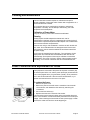
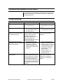
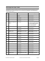
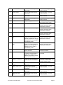
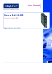
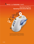
Laser Console
User’s Manual
Manufactured for:
Vascular Solutions, Inc.
6464 Sycamore Court
Minneapolis, MN 55369
763-656-4300
www.vascularsolutions.com
Vari-Lase Laser Console, Instruction Manual Copyright 2007
P/N 42-0472-01 Rev B 07/2007
Vari-Lase Laser Console User’s Guide
Page 1
Table of Contents
Table of Contents ..........................................................................................................................................2
Caution...........................................................................................................................................................3
Introduction ...................................................................................................................................................4
Intended Use..................................................................................................................................................4
.............................................................................................................................................4
Clinical Procedure.........................................................................................................................................6
Installation and User Obligations ................................................................................................................6
Important Safety Information .......................................................................................................................7
Labels and Symbols......................................................................................................................................8
Description of Operating Console ...............................................................................................................9
Operation .....................................................................................................................................................11
Output Power Verification ..........................................................................................................................13
Definition and Retrieval of Treatment Parameter Sets .............................................................................13
Remote Interlocking....................................................................................................................................14
System Set-up and Status Display Controls .............................................................................................15
Laser Settings .............................................................................................................................................16
Service / Adjustment Functions .................................................................................................................16
Cleaning and Maintenance .........................................................................................................................18
Power Connection and Replacement of Fuses.........................................................................................18
Connection and Release of Foot Switch ...................................................................................................19
Trouble Shooting.........................................................................................................................................19
Warnings and Stop Codes..........................................................................................................................20
Protective Eyewear .....................................................................................................................................23
Service .........................................................................................................................................................23
Storing and Transportation ........................................................................................................................23
Technical Specifications for the Vari-Lase Laser Console ......................................................................23
Guidance and Manufacturer’s Declaration – EMC Topics........................................................................25
Warranty Terms and Provisions ................................................................................................................28
Appendix A ..................................................................................................................................................29
P/N 42-0472-01 Rev B 07/2007
Vari-Lase Laser Console User’s Guide
Page 2
Caution
1.
2.
3.
4.
5.
6.
The Vari-Lase laser console is a Class 4 laser, which emits invisible
laser radiation.
Avoid exposure to direct or scattered radiation.
Patient, operator and others in contact with the laser must wear
suitable protective eyewear. Protective eyewear must be of a quality
corresponding to the standards IEC 825 and EN 207.
The Vari-Lase laser console should be used only with the Bright Tip
laser fiber.
Read the operating instructions thoroughly before connecting the
unit to the power and prior to use. The unit must be set, regulated
and used in accordance with the instructions for use. Failure to
observe usual safety precautions may present a risk of hazardous
exposure to laser radiation.
When the laser is not in use, ensure that it is rendered inaccessible
to unauthorized personnel. Remove the key to disable the unit.
Restrictions on use of Class 4 laser equipment
U.S. Federal Law restricts this device to sale by or on the order of a
physician.
The Vari-Lase laser system is intended solely for physicians trained in the
use of these instruments. The safety precautions for Class 4 laser
equipment must be followed. The physician is responsible for evaluating
each patient's suitability to undergo laser surgery and furthermore to
inform the patient about any risks involved, the actual treatment, pre- and
postoperative care and any other relevant information.
P/N 42-0472-01 Rev B 07/2007
Vari-Lase Laser Console User’s Guide
Page 3
Introduction
We congratulate you on the purchase of this Vari-Lase laser console,
among the most advanced and user-friendly diode lasers available. It
constitutes the fruition of many years of experience in the manufacturing
and development of high technology medical laser equipment.
Rigorous quality control and factory testing ensure the very highest levels
of quality and reliability.
The unit incorporates various fail-safe systems and conforms to
international standards for medical electrical equipment, IEC 601-1 and
those specifically for laser equipment IEC 601-2-22 and IEC 825.
This manual is intended to provide you with an overview of the operation
of this laser console. Further instructions regarding its use in particular
situations may be obtained in the Instructions for Use provided with the
Vari-Lase Endovenous Laser Procedure Kit.
Intended Use
Indications
The Vari-Lase procedure is indicated for the treatment of varicose veins
and varicosities associated with superficial reflux of the Great
Saphenous Vein and for treatment of incompetence and reflux of
superficial veins in the lower extremity.
Contraindications
The Vari-Lase procedure is contraindicated in patients with an
aneurysmal section in the vein segment to be treated.
The Vari-Lase procedure is contraindicated in patients with severe peripheral
vascular disease, as evidenced by an ankle-brachial index of < 0.5.
The Vari-Lase procedure is contraindicated in patients with thrombus in
the vein segment to be treated.
Warnings
Treatment of a vein located close to the skin surface may result in a skin burn.
Paresthesia may occur from thermal damage to adjacent sensory nerves.
Appropriate eye protection must be worn by the patient and all operating
personnel to protect from damage by direct or reflected laser energy.
Complications
As with all medical procedures, complications may occur. For the
endovenous laser treatment of varicose veins, these may include:
•
•
•
•
•
•
•
•
P/N 42-0472-01 Rev B 07/2007
vessel perforation
thrombosis
pulmonary embolism
phlebitis
hematoma
infection
paresthesia
skin burns
Vari-Lase Laser Console User’s Guide
Page 4
Precautions
The Vari-Lase procedure should be performed only by physicians who
are thoroughly trained in percutaneous, endovenous techniques and
procedures and knowledgeable in the use of this laser console.
Inspect the laser fiber before use and avoid touching the laser lenses
and Bright Tip fiber ends to avoid damage to the fiber and the instrument
optics.
Exercise care in handling of the Bright Tip laser fiber during the
procedure to reduce the possibility of accidental breakage, bending or
kinking.
Important Note
Additional information concerning the Bright Tip fiber handling and use
can be found in the instruction manual provided with the Bright Tip laser
fiber.
P/N 42-0472-01 Rev B 07/2007
Vari-Lase Laser Console User’s Guide
Page 5
Clinical Procedure
Follow the Instructions for Use accompanying the endovenous laser
procedure kit and components being used, and accepted medical
practice. The techniques, procedures and equipment described do not
represent ALL medically acceptable protocols, nor are they intended as
a substitute for the physicians experience and judgment in treating any
specific patient.
Each Vari-Lase Endovenous Laser Procedure will require the following
components:
•
•
•
•
Vari-Lase 810nm Laser Console
Safety eyewear for patient and all operating personnel
Duplex ultrasound console and transducer for mapping and
guidance
Procedure kit and sterile procedure pack
Installation and User Obligations
The Vari-Lase laser console is designed to operate within normal room
temperature (15-27°C/ 59-81°F) and humidity conditions. The unit must
be allowed to acclimatize before use following exposure to extreme
temperature or humidity. Do not install the unit close to radiators or other
sources of heat convection.
The unit may overheat due to excessive room temperature in
combination with operation at high output power. In case of overheating
the system will automatically shut down for a short cooling period. After a
few seconds the system will be ready for continued treatment.
We advise against the use of lasers at a distance of less than 2.5 meters
from short-wave or microwave equipment, since unstable laser
irradiation may occur.
No attempt should be made by unauthorized persons to open the unit
with a view to repair. Failure to observe this caution may present a
serious safety hazard and will void the warranty.
Vascular Solutions, Inc. cannot be held liable for events resulting from
negligence, abuse or incorrect operation of the unit. Please acquaint
yourself thoroughly with the instructions for use, and in the event of
doubt contact Vascular Solutions, Inc.
P/N 42-0472-01 Rev B 07/2007
Vari-Lase Laser Console User’s Guide
Page 6
Important Safety Information
The Vari-Lase laser console is designed and tested for maximum safety
for both the user and patient. It is however, ultimately the operator's
responsibility to introduce safe practices, which ensure the safety of
personnel and equipment.
Electrical safety
WARNING
Only Vascular Solutions authorized personnel should attempt to
inspect and/or repair the Vari-Lase laser console.
The system must be protectively connected to ground. If used in North
America at 220V, the power circuit must be center-tapped.
Avoid exposure to laser radiation in excess of the allowable limits listed
in Title 21 U.S. Code of Federal Regulation, parts 1040.10 and 1040.11,
during the installation and operation of the Vari-Lase laser console.
Optical safety
WARNING
Injury to the eyes and the epidermis can result from either direct or
scattered radiation. The power density of the light emitted from
lasers can be high enough to cause severe burns to the skin when
directly exposed to the beam.
WARNING
All personnel in the operating room must be protected from stray
and scattered radiation by wearing the appropriate protective
eyewear to guard against ocular injury. Never look directly into any
laser beam.
Use surgical instruments with a dull and dark anodized finish whenever
possible. Shiny surfaces can reflect laser beams. Take extreme care if
shiny surgical instruments are used.
Fire and explosion precautions
Combustible material can ignite if exposed to certain wavelengths of
laser radiation.
WARNING
Do not operate the laser in the presence of explosive gases and
liquids as well as highly concentrated oxygen.
The following precautions can minimize the danger of fire:
a. Surround the surgical field with wet gauze or towels.
b. If possible, eliminate flammable materials from the surgical field.
c. Have a fire extinguisher nearby.
Always place the laser in “Standby” mode whenever possible. This will
prevent accidental firing of the laser.
P/N 42-0472-01 Rev B 07/2007
Vari-Lase Laser Console User’s Guide
Page 7
Precautions against transfer of diseases
The cleansing and sterilization instructions provided by this manual must
always be followed to avoid transfer of diseases through patient contact
with operation components.
WARNING
Insufficient cleansing or sterilization of operation components that
come into contact with the patient may result in transfer of
diseases.
Labels and Symbols
The type plate is situated at the rear of the laser system.
Explanatory label and Laser Warning label must be affixed on the front of
the system.
Serial number plate is situated on the back panel of the console.
Symbol on type plate indicates Type BF Applied Part.
P/N 42-0472-01 Rev B 07/2007
Vari-Lase Laser Console User’s Guide
Page 8
Description of Operating Console
1.
2.
3.
4.
5.
6.
7.
8.
9.
10.
11.
12.
13.
14.
15.
16.
17.
P/N 42-0472-01 Rev B 07/2007
Selector - used for parameter selection.
Selector - used for parameter selection.
Selector - used for parameter selection.
Selector - used for parameter selection.
Program key. Provides the possibility of choosing any
preprogrammed set of treatment parameters.
Menu key. Provides access to the various menus.
Step Left key. This key is used for menu browsing and operation.
Step Right key. This key is used for menu browsing and operation.
Clear key. Used for resetting.
Enter key. Confirms the parameters currently displayed.
Jog Shuttle. Turning the jog shuttle clockwise will increase any
selected parameter, turning it counter-clockwise will decrease the
parameter.
Ready key. When activated the laser is ready to emit energy. See
“Operation” section on page 10 for more details.
Standby key. When activated, the Vari-Lase laser console is
placed in “Standby” mode. Parameters can be modified, but no
laser output can be generated.
Emergency Stop key. See “Operation” section on page 10.
Laser Ready Indicator. Lit when the Vari-Lase laser console is
placed in Ready mode and foot switch is not activated.
Laser Emission Indicator. Lit when laser emission occurs.
Key switch. Unit is disabled when the key is in off-position or when
the key is removed. Lit when the unit is activated.
Vari-Lase Laser Console User’s Guide
Page 9
18. Bright Tip Fiber Connection. Laser pulses are delivered via a fiber
assembly.
19. Not currently in use.
20. Slot for Code Plug connected to the fiber.
21. Laser Beam Input Port for verification purpose. See paragraph
“Output Power Verification” on page 12.
22. Release button for air foot switch connector.
23. Connector for air foot switch.
24. Connector for Remote Interlock.
25. Power Switch.
26. Power Lead Connector.
27. Fuse Holder and Voltage Selector, see paragraph “Power
Connection and Replacement of Fuses” on page 17.
24
25
P/N 42-0472-01 Rev B 07/2007
Vari-Lase Laser Console User’s Guide
26
27
Page 10
Operation
Preparing for use
1.
2.
3.
Plug the foot switch tube into the socket (23).
Switch on the power switch at the rear of the unit (25).
Connect interlocking or insert dummy plug in the connector located
at the rear of the unit (24).
4. Enable the unit by inserting and turning the key in the switch (17).
Check that the indicator above the switch is lit.
5. Visually inspect the QSC adapter lens for contamination or damage.
6. Insert code plug with QSC connector.
SMA-to-QSC
7. Remove the protection cap from
adapter
the Bright Tip laser fiber
connector.
8. Insert the Bright Tip laser fiber
connector carefully in the SMA
socket of the SMA-to-QSC
adapter. Tighten the screw
carefully.
9. Remove plug from the laser port.
10. Insert the SMA-to-QSC adapter in the Vari-Lase laser console. The
SMA-to-QSC adapter is marked with a plate showing an
appropriate reference number (50xxx).
400µm fibers. To facilitate the use of 400µm fibers, the QSC-SMA
adapter (Ref 50600) must be used.
600µm fibers. To facilitate the use of 600µm fibers, the QSC-SMA
adapter (Ref 50599) must be used.
Caution. Always use the correct combination of fiber and QSCSMA adapter. Incorrect use may lead to severe damage to the fiber,
the QSC-SMA adapter or the laser console.
Caution. Keep the fiber cap on when the fiber system is not
connected. Do not touch the fiber connector tip, as this will reduce
the fiber’s lifespan.
11. While the Vari-Lase laser console is powering up, laser emission is
disabled, all keys and selectors are disabled, and parameters are
set to default
WARNING
Do not place the QSC adapter into the laser console without a
Bright Tip fiber connected, or else the laser beam may be activated.
12. Set the treatment parameters (see below).
13. Bring the Vari-Lase laser console into “Ready” mode by pressing
the Ready key (12). After a required 3 seconds safety-delay, the
unit will become ready and the Laser Ready indicator (15) will be lit.
P/N 42-0472-01 Rev B 07/2007
Vari-Lase Laser Console User’s Guide
Page 11
14. Start treatment, using the foot switch. Each time the foot switch is
activated, laser radiation will be emitted and the Laser Emission
Indicator (16) will be lit.
Setting of treatment parameters
Power, fluence, pulse width, and pulse repetition rate can be set to
prepare for the required treatment. Operating the selectors (1, 2, 3, and
4) and the jog shuttle (11) does the setting.
The treatment parameter to be set is selected by pressing the
associated selector (1, 2, 3, or 4) located below the display. When a
parameter is selected, it can be modified by turning the jog shuttle.
When all parameters are properly set for treatment, press ↵ (10) to
enter the parameters. One can also press the Ready key (12) to enter
the parameters and bring the unit directly into “Ready” mode. Pressing
the C key (9) during setting of a parameter terminates the setting
without changing the parameter.
Output power
The output power level is shown in the display.
Fluence
The fluence level is shown in the display.
Pulse width
The pulse width is shown in the display.
Pulse repetition frequency
Output can be set to single pulse or CW. The frequency is shown in the
display.
Please note: Fluence is a physical property closely connected to output
power and pulse width. Hence, changing one treatment parameter may
unavoidably affect the others. To ease operation the Vari-Lase laser
console automatically re-computes and updates all affected parameters
when power, fluence, or pulse width is set by the user. Further, due to
the dependency between the parameters, maximum value of fluence,
pulsewidth, and frequency depends on the setting of the other
parameters.
Standby mode and Ready mode
When the Ready key is pressed, the unit enters “Ready” mode. In this
mode, laser radiation will be emitted when the foot switch is pressed.
Pressing the M, C, or P key or any selector key will return the system to
“Standby” mode.
Ready
Standby
P/N 42-0472-01 Rev B 07/2007
When the Standby key is pressed, the unit enters “Standby” mode. For
safety reasons the laser should always be brought into “Standby” mode
whenever not treating. In “Standby” mode laser radiation cannot be
emitted.
If the system remains idle in “Ready” mode for 250 seconds, it will
automatically return to “Standby” mode for the sake of operator and
patient safety.
Vari-Lase Laser Console User’s Guide
Page 12
Start and stop of laser radiation
CAUTION
When the Laser Ready Indicator is on, the Vari-Lase laser console
emits radiation immediately upon activation of the foot switch.
When the laser is active, the yellow Laser Emission Indicator flashes
and an audible tone signal will be heard.
Foot Switch Operation
When the foot switch is pressed, the Vari-Lase laser console starts
radiating. Releasing the footswitch stops emission.
Emergency Stop Key
When the Emergency Stop Key (14) is pressed the Vari-Lase laser
console stops emitting radiation and all functions are blocked. The
power switch (25) must be turned OFF for approximately 15 seconds
and ON again for restart.
Output Power Verification
The Vari-Lase laser console provides advanced built-in facilities for
output power verification purpose.
1.
2.
3.
4.
5.
6.
Press the M key (6) to enter the Function Menu.
Press the “Measure Power” selector (1).
Align the tip of the handpiece with the sensor opening (21) and
keep it aligned during the entire measuring process.
Activate the footswitch - and keep the footswitch pressed during
the whole measuring process. Any measurement interrupted by
the release of the footswitch will be ignored.
The Vari-Lase laser console automatically tests the laser output by
measuring the power level of a number of pulses - wait for this to
complete.
The measured output, stated in terms of percentage of expected
output, is displayed. Repeated measurements may cause the
built-in power meter to heat up. If so, a message will appear urging
the user to wait 5 minutes before further measurements are
undertaken.
CAUTION
All personnel in the operating room must be protected by
protective eyewear during the measurement.
Definition and Retrieval of Treatment Parameter Sets
The Vari-Lase laser console features the possibility of defining 16
different sets of treatment parameters, which can later be retrieved for
fast unit set-up.
The parameters are not affected by unit power-off.
P/N 42-0472-01 Rev B 07/2007
Vari-Lase Laser Console User’s Guide
Page 13
Definition and storage of a parameter set
Go through the following steps to define a set of treatment parameters
for later retrieval:
1.
2.
3.
4.
5.
6.
7.
Make sure the unit is in laser “Standby” mode.
Use the Selector keys (1 through 4) and the Jog Shuttle (11) to
define a set of treatment parameters.
Press the M key (6) to enter the Function Menu.
Press Selector (4) to enter the “Save Program” function.
Turn the Jog Shuttle (11) to assign a unique number to the defined
set of parameters. Any set previously assigned this number will be
overridden.
For easy operation, an optional textual name may be assigned too.
To do this, press Selector key (2) to enter the “Change-name”
function; use the Step Left (7), Step Right (8), and the Jog Shuttle
(11) to spell out the textual name.
Press Selector key (4) to save the parameter set together with the
assigned number and name. Or press the Selector key (3) to exit
without saving the parameters.
Retrieving a parameter set
Go through the following steps to retrieve a predefined set of
parameters:
1.
2.
Press the P key (5);
Turn the Jog Shuttle (11) until the number or name of the desired
set of parameters appears in the upper rightmost corner of the
display;
3.
Press ↵ (10) or the P key (5) to select the parameters for
treatment; or press the Ready key (12) to select the parameters
and bring the unit directly into ready mode.
Remote Interlocking
The Vari-Lase laser console provides an interlocking feature that can be
employed for deactivation of laser emission when doors are opened to
the treatment area.
If remote interlocking is not required
The unit is supplied with a special interlocking dummy plug that must be
inserted in the interlocking socket (24) in case no interlocking is
required.
If remote interlocking is required
If the interlocking feature is required to ensure a safe entry to the
treatment area, an appropriate micro-switch may be mounted on the
doorframe in a way that ensures contact closure when the door is
closed.
The jumper between pin 2 and 5 of the dummy plug must be removed
and the micro-switch must be wired to these pins instead. Multiple
doors can be wired in series if needed.
P/N 42-0472-01 Rev B 07/2007
Vari-Lase Laser Console User’s Guide
Page 14
System Set-up and Status Display Controls
A number of system features, which may be set up by the user, exist.
To do this please follow the below procedure:
1. Make sure the unit is in “Standby” mode;
2. Press the M key (6) to enter the Function Menu;
3. Press Selector (2) to enter the User Setup function.
Four set-up options will be displayed. Press the Step Right or the M key
to display two more. These six options are described below:
Sound Level
Turn the Jog Shuttle to change the volume of the internal speaker.
Press ↵ (10) when a satisfactory volume is found.
Display Contrast
Turn the Jog Shuttle to change the display contrast. Press ↵ (10) when
a satisfactory display contrast is found.
Aiming Beam
Turn the Jog Shuttle to adjust the brightness of the aiming beam. Press
↵ (10) when the desired brightness is found. The effect will be visible
next time “Ready” mode is entered.
Choose Language
Turn the Jog Shuttle to see the languages, which can be used for
display text. Press ↵ (10) when the desired language is found.
Status Display 1 / Status Display 2
The user can choose two selectable status readings to be displayed
during operation. The two readings can be chosen from a group of four:
•
None: No status is displayed
•
Pulses: The number of pulses generated
•
ActiveTime: The amount of time laser has been radiated
•
Joules: The amount of joules generated
One reading is chosen by using menu entry “Status Display 1” and the
other by using menu entry “Status Display 2.” Use the Jog Shuttle to
browse through the four options. Press ↵ (10) when the desired status
reading is found. The reading will be displayed whenever the unit is in
“Standby” or “Ready” mode.
The user may want to reset the readings; e.g. before a patient treatment
is initiated. To do this, please follow the below procedure:
1.
2.
3.
P/N 42-0472-01 Rev B 07/2007
Make sure the unit is in “Standby” mode.
Press the M key (6) to enter the Function Menu.
Press Selector (3) to reset the status display readings.
Vari-Lase Laser Console User’s Guide
Page 15
Laser Settings
The Vari-Lase laser console permits the user to change the fiber system
and still gain the full benefit of the displayed operation parameters.
Service / Adjustment Functions
The Vari-Lase laser console provides the user with various features for
setting and reading of equipment parameters. These adjustable
parameters are organized into six service groups that can be accessed
when the unit is in “Service” mode. Follow the procedure below to enter
“Service” mode:
1. Make sure the unit is in “Standby” mode.
2. Press the M key.
3. Press Step Right.
4. Press the Service Setup selector.
5. The unit is now brought into “Service” mode.
The following six groups of service settings are accessible to the user:
USER SETTINGS: Standard user controls like display contrast, sound
level, etc.
ACCESS CODES: Access codes can be entered for service or
maintenance purpose. For safety reasons access is only granted to
authorized personnel.
UNIT IDs: Reports various IDs associated with each individual VariLase laser console.
CODEPLUG SETTINGS: Standard user set-up values which are stored
in the Code Plug.
TIME LOG: This group contains time logging and timing functions.
LOG FUNCTIONS: Provides the possibility of copying the internal unit
operation log to the Code Plug, which can then be sent to the Vari-Lase
laser console manufacturer for inspection.
Service mode controls
•
Use the Jog Shuttle to browse the service settings.
•
Use the Step Left or Step Right keys to change from one group of
service settings to another.
•
Use the Change selector to enable changing of a parameter (please
note, the Change feature only exists for a subset of the parameters).
•
There are two types of parameter input modes:
•
Limited Range Parameters: Operate the Jog Shuttle to change
the parameters. Press the Save selector to store the new value.
•
Large Number Selection. Operate the Jog Shuttle to change the
value of the current digit. Press Step Right or Step Left to select
another digit. Press the Save selector to store the new value.
The service settings are described in more detail in the following table.
P/N 42-0472-01 Rev B 07/2007
Vari-Lase Laser Console User’s Guide
Page 16
USER SETTINGS
100
101
102
103
104
Sound Level
This setting changes the volume of the internal speaker. The volume changes instantly, but
will not be saved until “Save” is pressed.
Display Contrast
This setting changes the contrast of both displays. The contrast changes instantly, but will
not be saved until “Save” is pressed.
Language
This setting changes the language used for displayed text.
Status Display 1
This setting features the selection of status reading 1 (as described on page 14) to be
displayed.
Status Display 2
This setting features the selection of status reading 2 (as described on page 14) to be
displayed.
ACCESS CODES
200
Access Code
This setting is to be used by authorized service personnel only.
UNIT IDs
300
301
304
Serial Number
The unit serial number is displayed here.
Type Number
The unit type number is displayed here.
SW Version
The software version is displayed here.
CODEPLUG SETTINGS
418
419
Aiming Beam Level
Brightness of the aiming beam. The brightness changes instantly but will not be saved until
“Save” is pressed.
Aiming Beam Color
Determines the color of the aiming beam.
TIME LOG
500
501
509
Power On Time
Reports the total power-on time of the laser in minutes.
Laser Active Total Time
Reports the total Laser Active time at any power level in minutes.
Total Joules
Reports the total number of joules emitted from the laser.
LOG FUNCTIONS
1101
Copy Log to Code Plug
Press Selector key (4) to copy the entire contents of Internal Apparatus Log and all the
internal laser settings to the inserted Code Plug. Press Selector key (1) to confirm and wait
for the copying to complete, it may take some time. The log is stored in a previously unused
part of the Code Plug; all previous Code Plug contents remains unchanged, and the system
can be used as normal.
P/N 42-0472-01 Rev B 07/2007
Vari-Lase Laser Console User’s Guide
Page 17
Cleaning and Maintenance
The Vari-Lase laser console requires no maintenance except for
periodic calibration of the power meter. Please refer to Appendix A for a
routine maintenance schedule.
Do not expose the unit or accessories to moisture or extremes of
temperature or humidity. Do not attempt to sterilize any part of the
equipment but the handpieces.
Calibration of Power Meter
Every 24 months the power meter should be recalibrated.
Cleaning
Visually inspect the QSC adapter lens before each use for
contamination or damage. Use only compressed air to clean the lens if
contamination is present. Replace the QSC adapter if the contamination
cannot be removed with compressed air.
Clean the unit using a cloth moistened in a mixture of 30% alcohol and
70% water. Pure undiluted alcohol or detergents should not be used.
During cleaning, the unit must be switched off and disconnected from
the power supply.
Any dirt must be cleaned from the fiber lens. The combination of high
output power and a delicate fiber necessitates a clean fiber lens to
avoid damage. Even specks of dust may be sufficient to cause fatal
contamination. The touch of a finger, rubbing of the tip against a piece
of clothing, or occurrence of airborne dust can contaminate the lens.
Power Connection and Replacement of Fuses
The equipment is connected to the power via the power connector (26)
on the back panel of the unit, and the power switch (25) is switched ON.
The unit is equipped with 2 pcs. glass fuses (T6.3AL), which protect the
unit in case of electrical fault. If the unit cannot be switched on, try to
replace the fuses before the unit is sent in for repair.
To replace the fuses:
25
26
27
P/N 42-0472-01 Rev B 07/2007
1. Remove the power cord.
2. Refer to the picture to the left. Insert a screwdriver into the small
slot as shown, and release the fuse socket by wrenching the
screwdriver.
3. Pull out the fuse socket (27).
4. Replace the fuses and re-insert the fuse socket.
The fuse socket can be inserted in either of the two possible directions,
as the Vari-Lase laser console automatically switches to the actual input
voltage. When inserting the fuse socket for 220V power supply in North
America, the outlet must be of the center-tapped type.
Vari-Lase Laser Console User’s Guide
Page 18
Connection and Release of Foot Switch
A connector (23) for the foot switch is provided on the front panel. For
connection simply plug in the foot switch connector. For release, push
the release button (22).
Trouble Shooting
Symptom
Possible Cause
Recommendation
No light in display when switched
on
•
•
Low output power
•
•
Defective power fuses
Low power supply
•
Defective fiber
•
Low pulse width combined
•
with low frequency
Decrease the value of one or
Fluence is a physical property
closely connected to output power more of the other treatment
parameters
and pulse width. Due to the
dependency between the
parameters, maximum value of
fluence, pulse width and
frequency depends on the setting
of the other parameters.
•
Fluence, pulse duration, or
frequency cannot be set as high
as it could be previously
A temperature fault message is
displayed and the Vari-Lase laser
console stops radiating
•
•
Aiming beam has faded or is
looking diffused
P/N 42-0472-01 Rev B 07/2007
Change fuses
Wait at least 5 sec for power
up
Change fiber
Choose higher pulse width
Overheated diode due to
combination of high room
temperature, high power
setting and high duty cycle
Internal laser cooling system
ineffective
As the aiming beam passes
through the same optical system
as the working beam, it provides
a good method of checking the
unit. If the aiming beam spot is
not present at the distal end of the
fiber, its intensity is reduced or if it
looks diffused, the fiber might be
damaged.
•
Wait a few seconds for the
system to cool down. If the
problem remains try to reduce
room temperature. Reduce
output power. Reduce duty
cycle (shorter dwell time,
longer breaks).
•
Return for repair. Call
Vascular Solutions, Inc.,
Customer Service
Check the unit by undertaking an
output power verification as
described in the paragraph
“Output Power Verification” on
page 12.
Vari-Lase Laser Console User’s Guide
Page 19
Warnings and Stop Codes
The table below provides a complete overview over the various warnings and fault messages that can be
displayed by the Vari-Lase laser console. If one of the faults occurs repeatedly, note the message and
contact Vascular Solutions.
Error
code
Error message
Cause
Recovery
0
EMERGENCY STOP
Emergency button has been
pressed.
Laser shuts down. Cycle key
switch to recover.
1
I/O SYSTEM FAULT
This is an internal laser system
fault situation.
Laser shuts down. Cycle key
switch to recover.
2
DETECTOR STOP
This is an internal laser system
fault situation.
Laser shuts down. Cycle key
switch to recover.
3
OVER CURRENT STOP
(REDUCE POWER AND
RETRY)
This is an internal laser system
fault situation.
All laser circuits are shut down.
Cycle key switch to recover/retry.
Note: Do not repeatedly provoke
an over-current stop. The laser
diodes could be damaged.
Reduce power and retry.
4
POWER HIGH FAULT
This is an internal laser system
fault situation.
Laser shuts down. Cycle key
switch to recover.
5
POWER LOW FAULT
This is an internal laser system
fault situation.
Laser shuts down. Cycle key
switch to recover.
6
VDIODE FAULT
This is an internal laser system
fault situation.
Laser shuts down. Cycle key
switch to recover.
7
5V MIN FAULT
This is an internal laser system
fault situation.
Laser shuts down. Cycle key
switch to recover.
8
5V MAX FAULT
This is an internal laser system
fault situation.
Laser shuts down. Cycle key
switch to recover.
9
10V MIN FAULT
This is an internal laser system
fault situation.
Laser shuts down. Cycle key
switch to recover.
10
10V MAX FAULT
This is an internal laser system
fault situation.
Laser shuts down. Cycle key
switch to recover.
11
10V SCAN MIN FAULT
This is an internal laser system
fault situation.
Laser shuts down. Cycle key
switch to recover.
12
10V SCAN MAX FAULT
This is an internal laser system
fault situation.
Laser shuts down. Cycle key
switch to recover.
13
12V MIN FAULT
This is an internal laser system
fault situation.
Laser shuts down. Cycle key
switch to recover.
14
12V MAX FAULT
This is an internal laser system
fault situation.
Laser shuts down. Cycle key
switch to recover.
15
32V MIN FAULT
This is an internal laser system
fault situation.
Laser shuts down. Cycle key
switch to recover.
16
32V MAX FAULT
This is an internal laser system
fault situation.
Laser shuts down. Cycle key
switch to recover.
P/N 42-0472-01 Rev B 07/2007
Vari-Lase Laser Console User’s Guide
Page 20
17
-5V MIN FAULT
This is an internal laser system
fault situation.
Laser shuts down. Cycle key
switch to recover.
18
-5V MAX FAULT
This is an internal laser system
fault situation.
Laser shuts down. Cycle key
switch to recover.
19
-5V UREG MIN FAULT
This is an internal laser system
fault situation.
Laser shuts down. Cycle key
switch to recover.
20
-5V UREG MAX FAULT
This is an internal laser system
fault situation.
Laser shuts down. Cycle key
switch to recover.
21
POWER DOWN
Low power supply.
Saves data internally and shuts
down system. Check power.
22
TEMPERATURE 1 STOP
Laser diode temperature high.
The laser is shut down. Normal
operation will resume when
temperature is reduced.
23
TEMPERATURE HIGH
Internal temperature is too high.
The laser is shut down. Normal
operation will resume when
temperature is reduced.
24
TEMPERATURE 2 STOP
Laser diode temperature high.
The laser is shut down. Normal
operation will resume when
temperature is reduced.
25
PFC TEMPERATURE
STOP
This is an internal laser fault
The laser is shut down. Normal
situation. The Power Factor
operation will resume when
Controller temperature is too high. temperature is reduced.
This temperature can be preset in
Service/Setting mode.
26
DRIVER TEMPERATURE This is an internal laser fault
STOP
situation. The Laser Diode Driver
temperature is too high. This
temperature can be preset in
Service/Setting mode.
27
CONNECT FIBER
All laser controls are disabled until Resumes normal operation when
a fiber is mounted.
the fiber is mounted.
28
CONNECT INTERLOCK
All laser controls are disabled until Resumes normal operation when
an interlock connector/switch is
connected.
installed. Pin 2 (GND) and 5
(Interlock input) must be shorted
on the interlock connector.
29
CONNECT CODEPLUG
All laser controls are disabled until Resumes normal operation when
a Code Plug has been installed.
connected, but clears user
settings to default values.
30
CONNECT SENSOR
BOARD
This is an internal laser system
fault situation.
Laser shuts down. Cycle key
switch to recover.
31
AIMING LASER FAULT
The aiming laser draws an
unusually high current and might
be damaged.
Laser shuts down. Cycle key
switch to recover.
32
SETTING WRITE ERROR This is an internal laser system
fault situation.
Laser shuts down. Cycle key
switch to recover.
33
IIC BUS RELEASE
FAULT
Laser shuts down. Cycle key
switch to recover.
P/N 42-0472-01 Rev B 07/2007
This is an internal laser system
fault situation.
The laser is shut down. Normal
operation will resume when
temperature is reduced.
Vari-Lase Laser Console User’s Guide
Page 21
34
CONNECT FB SENSOR
This is an internal laser system
fault situation.
Laser shuts down. Cycle key
switch to recover.
35
EEPROM PAGE ERROR
This is an internal laser system
fault situation.
Laser shuts down. Cycle key
switch to recover.
36
VAUX MIN FAULT
This is an internal laser system
fault situation.
Laser shuts down. Cycle key
switch to recover.
37
VAUX MAX FAULT
This is an internal laser system
fault situation.
Laser shuts down. Cycle key
switch to recover.
38
PARAMETER ERROR
Parameter(s) in the Code Plug or
laser is out of range. Pressing the
Standby key will initialize the
parameters to default values.
Laser output is disabled. Resumes
normal operation when the
Standby key has been pressed.
39
PULSE TIMING ERROR
This is an internal laser system
fault situation.
Laser shuts down. Cycle key
switch to recover.
40
SAFETY PARAMETER
ERROR
This is an internal laser system
fault situation.
Laser shuts down. Cycle key
switch to recover.
41
CENTRE DIODE
TEMPERATURE STOP
Laser diode temperature high.
The laser is shut down. Normal
operation will resume when
temperature is reduced.
42
ATTACHED SCANNER IS A scanner which is not compatible Check whether the scanner is a
NOT COMPATIBLE
with the laser is attached.
type intended to be compatible.
Check whether the scanner or the
scanner cable is damaged. Cycle
key switch.
43
SCANNER ERROR
An error has occurred while
interfacing to the scanner.
Check whether the scanner or the
scanner cable is damaged. Cycle
key switch.
44
DIODE TEMP HIGH
FAULT
A high diode temperature is
measured.
All fans will be working at full
speed to cool the system.
P/N 42-0472-01 Rev B 07/2007
Vari-Lase Laser Console User’s Guide
Page 22
Protective Eyewear
Protective eyewear must be of a quality corresponding to the standards
IEC 825 and EN 207. According to these specifications, the protective
eyewear must be marked with the following:
Type of laser:
Wavelength:
Protective class :
D
800-830nm
L4
(Continuous wave laser)
(Or larger wavelength interval)
(Or higher)
Service
In the event of malfunction or fault, please contact Vascular Solutions, Inc. Customer Service at 888-2406001 or 763-656-4300.
Storing and Transportation
The system should be stored under temperature conditions in the range
of 0-50°C (32-122°F), air humidity below 80%, and air pressure > 0.7
atm. If transporting the unit to other destinations (for instance to another
clinic or in connection with service), the Vari-Lase laser console should
always be transported in the original packaging material. When returned
to Vascular Solutions for service or repair, the equipment must be
shipped in the original packing material to avoid any damage during
transportation.
Technical Specifications for the Vari-Lase Laser Console
Laser Type:
Output Power:
Continuous Wave Diode Laser. Laser Class 4 (IEC825)
Range
Maximum
Precision
Mode of Operation:
Wavelength:
Target Indicator:
Fiber Connection:
Fiber Diameter:
Numerical Aperture of Fiber:
Start/Stop Functions:
Emergency Stop:
Warning Signals for Laser
Radiation:
1W to 30W in steps of 1W
35W, depending on transmission in connected fiber
Better than 10% at maximum output power
Pulsed beam or continuous wave
810nm ± 10nm
Red indicator light through fiber (635nm)
Quick Safe Connect
600µm or 400µm
0.37 or larger
Foot switch
Large button on front panel
P/N 42-0472-01 Rev B 07/2007
Flashing yellow indicator and intermittent sound
Vari-Lase Laser Console User’s Guide
Page 23
Laser Ready Warning:
Laser Ready Time-Out:
Emission:
Frequency Range
Pulse Width
Nominal Ocular
Hazard Distance
Beam Divergence
Output Power Meter:
Range
Accuracy
Protection Against Ingress of
Water:
Power Supply:
Power Consumption:
Indication of Power Connection:
Fuses:
Patient Leakage Current:
Earth Leakage Current:
Operating Environment:
Yellow indicator on front panel and target indicators
250 seconds
Min. 0.3Hz / Max. 100Hz
10 - 1000 msec
Bare fiber: 10m
Bare fiber: 0.7 rad
1W to 150W
Better than ± 20%
Class IPX0
Power connection (100-240V, 50/60Hz).
North America: use center-tapped circuit when connecting the
equipment to 240V, single-phase power.
30 - 300 VA
Green indicator
2 pcs T6.3 AL
Typically 0 (< 100µA)
Typically 300µA (< 500µA)< 300µA at 110V and at center-tapped 240V
Room temp. 15-27°C/ 59-81°F,
Humidity 10-80%, Air pressure > 0.7 atm
1 type BF
Safety Class:
Application in Presence of
Flammable Anaesthetic Mixtures: Not suited
Size:
51.5 x 30.0 x 15.0cm
Weight:
Approx. 12kg
EMC Regulations and Testing
EMC specifications are tested under the following conditions:
•
Air foot activator was used.
•
Interlock function was connected to a 3m non-shielded cable.
•
Accessory connector was connected to a 3m non-shielded cable.
•
Connected optical fibre was found to be of no influence to the EMC test results.
The system is developed and tested in accordance with the following regulations covering electrical and
laser safety:
EN 60601-1 + A1
Electrical safety
EN 60601-1-1
Medical electrical equipment
EN 60601-1-4
Medical systems with software
IEC 601-2-22
Particular requirements for the safety of diagnostic and therapeutic laser
equipment
IEC 825-1
Safety of laser products
The following regulations and standards has been used to obtain the necessary EMC approvals:
IEC 601-1-2
P/N 42-0472-01 Rev B 07/2007
Vari-Lase Laser Console User’s Guide
Page 24
Guidance and Manufacturer’s Declaration – EMC Topics
Guidance and manufacturer’s declaration – electromagnetic emissions
The Vari-Lase Laser Console is intended for use in the electromagnetic environment specified below. The
customer or the user of the system should assure that it is used in such an environment.
Emissions test
Compliance
Electromagnetic environment - guidance
RF emissions
CISPR 11
Group 1
RF emissions
CISPR 11
Class B
Harmonic emissions
IEC 61000-3-2
Voltage fluctuations/
flicker emissions
Class A
Complies
Vari-Lase Laser Console uses RF energy only for its internal
function. Therefore, its RF emissions are very low and are not
likely to cause any interference in nearby electronic equipment.
Vari-Lase Laser Console is suitable for use in all
establishments, including domestic establishments and those
directly connected to the public low-voltage power supply
network that supplies buildings used for domestic purposes.
Guidance and manufacturer’s declaration – electromagnetic immunity
The Vari-Lase Laser Console is intended for use in the electromagnetic environment specified below. The
customer or the user of the system should assure that it is used in such an environment.
Immunity test
IEC 60601 test level
Compliance level
Electromagnetic environment
- guidance
Electrostatic
discharge (ESD)
IEC 61000-4-2
± 6kV contact
± 8kV air
± 6kV contact
± 8kV air
Electrical fast
transient/burst
IEC 61000-4-4
± 2kV for power supply
lines
± 1kV for input/output
lines
± 2kV for power supply
lines
± 1kV for input/output
lines
Surge
IEC 61000-4-5
± 1kV differential mode
± 2kV common mode
± 1kV differential mode
± 2kV common mode
Voltage dips, short
interruptions and
voltage variations on
power supply input
lines
IEC 61000-4-11
<5% UT (>95% dip in
UT) for 0,5 cycle
40% UT (60% dip in
UT) for 5 cycles
70% UT (30% dip in
UT) for 25 cycles
<5% UT (>95% dip in
UT) for 5 sec.
<5% UT (>95% dip in
UT) for 0,5 cycle
40% UT (60% dip in UT)
for 5 cycles
70% UT (30% dip in UT)
for 25 cycles
<5% UT (>95% dip in
UT) for 5 sec.
Power frequency
(50/60Hz) magnetic
field
IEC 61000-4-8
3A/m
3A/m
Floors should be wood,
concrete or ceramic tile. If floors
are covered with synthetic
material, the relative humidity
should be at least 30% RH.
Mains power quality should be
that of a typical commercial or
hospital environment.
Mains power quality should be
that of a typical commercial or
hospital environment.
Mains power quality should be
that of a typical commercial or
hospital environment. If the user
of the Vari-Lase Laser Console
requires continued operation
during power mains
interruptions, it is recommended
that the system be powered
from an uninterruptible power
supply or a battery.
Power frequency magnetic
fields should be at levels
characteristic of a typical
location in a typical commercial
or hospital environment.
NOTE: UT is the AC mains voltage prior to application of the test level.
P/N 42-0472-01 Rev B 07/2007
Vari-Lase Laser Console User’s Guide
Page 25
Guidance and manufacturer’s declaration – electromagnetic immunity
The Vari-Lase Laser Console is intended for use in the electromagnetic environment specified below. The
customer or the user of the system should assure that it is used in such an environment.
Immunity test
IEC 60601 test level
Compliance level
Electromagnetic environment
- guidance
Portable and mobile RF
communications equipment
should be used no closer to any
part of the Vari-Lase Laser
Console, including cables, than
the recommended separation
distance calculated from the
equation applicable to the
frequency of the transmitter.
Recommended separation
distance:
Conducted RF
IEC 61000-4-6
3Vrms
150kHz to 80MHz
3Vrms
d = 1 .2 P
d = 1.2 P 80M to 800MHz
Radiated RF
IEC 61000-4-3
3V/m
80MHz to 2.5GHz
3V/m
d = 2.3 P 800M to 2.5GHz
where P is the maximum output
power rating of the transmitter
in Watts (W) according to the
transmitter manufacturer and d
is the recommended separation
distance in metres (m).
Field strengths from fixed RF
transmitters, as determined by
an electromagnetic site surveya,
should be less than the
compliance level in each
frequency rangeb.
Interference may occur in the
vicinity of equipment marked
with the following symbol:
NOTE 1: At 80MHz and 800MHz, the higher frequency range applies.
NOTE 2: These guidelines may not apply in all situations. Electromagnetic propagation is affected by
absorption and reflection from structures, objects and people.
a
Field strengths from fixed transmitters, such as base stations for radio (cellular/cordless) telephones
and land mobile radios, amateur radio, AM and FM radio broadcast and TV broadcast cannot be
P/N 42-0472-01 Rev B 07/2007
Vari-Lase Laser Console User’s Guide
Page 26
predicted theoretically with accuracy. To assess the electromagnetic environment due to fixed RF
transmitters, an electromagnetic site survey should be considered. If the measured field strength in the
location in which the Vari-Lase Laser Console is used exceeds the applicable RF compliance level
above, the Vari-Lase Laser Console should be observed to verify normal operation. If abnormal
performance is observed, additional measures may be necessary, such as reorienting or relocating the
Vari-Lase Laser Console.
b
Over the frequency range 150kHz to 80MHz, field strengths should be less than 3V/m.
Recommended separation distances between portable and mobile RF communications equipment
and the Vari-Lase Laser Console
The Vari-Lase Laser Console is intended for use in an electromagnetic environment in which radiated RF
disturbances are controlled. The customer or the user of the Vari-Lase Laser Console can help prevent
electromagnetic interference by maintaining a minimum distance between portable and mobile RF
communications equipment (transmitters) and the Vari-Lase Laser Console as recommended below,
according to the maximum output power of the communications equipment.
Rated maximum
Separation distance according to frequency of transmitter / m
output power of
150kHz to 80MHz
80MHz to 800MHz
800MHz to 2.5GHz
transmitter / W
0.01
0.1
1
10
d = 1.2 P
d = 1.2 P
d = 2.3 P
0.12
0.38
1.2
3.8
0.12
0.38
1.2
3.8
0.23
0.73
2.3
7.3
100
12
12
23
For transmitters rated at a maximum output power not listed above, the recommended separation distance d
in metres (m) can be estimated using the equation applicable to the frequency of the transmitter, where P is
the maximum output power rating of the transmitter in watts (W) according to the transmitter manufacturer.
NOTE 1: At 80MHz and 800MHz, the separation distance for the higher frequency range applies.
NOTE 2: These guidelines may not apply in all situations. Electromagnetic propagation is affected by
absorption and reflection from structures, objects and people.
P/N 42-0472-01 Rev B 07/2007
Vari-Lase Laser Console User’s Guide
Page 27
Warranty Terms and Provisions
This equipment has been manufactured by MedArt A/S (Asah Medico
A/S) for Vascular Solutions, Inc. to rigorous standards of production and
quality control based on international standards.
In the event of a fault or breakdown which may be attributable to faulty
production or materials, Vascular Solutions, Inc., will make good all
repairs within a period of one year from the date of purchase.
The warranty covers all repair costs including labor resulting from
malfunction or fault arising from normal use of the equipment as
described in the instruction manual issued by Vascular Solutions, Inc.
and supplied with the equipment. The warranty shall only entitle the
buyer the right to request repair or replacement of defective parts of the
goods.
Please note that this warranty does not extend to fibers, consumables,
eyewear and other accessories which may be supplied with the
equipment.
Furthermore, Vascular Solutions, Inc. shall in no event be liable for
operating loss, loss of time or profits or any similar consequential or
indirect losses. Only if personal injury or damage to property is caused
directly by a defect in the products supplied, which defect may be
ascribed to Vascular Solutions, Inc., shall Vascular Solutions, Inc. be
liable for defects in components supplied by others to Vascular
Solutions, Inc.
The equipment should always be handled with care. When returned for
repair, the equipment should therefore be shipped in the original
packing material or alternative packaging supplied by Vascular
Solutions, Inc., to avoid any damage during transportation.
P/N 42-0472-01 Rev B 07/2007
Vari-Lase Laser Console User’s Guide
Page 28
Appendix A
TABLE A-1
ROUTINE MAINTENANCE SCHEDULE
Service
Frequency
Performed by
Check the exterior of the unit
making certain that there are no
loose electrical connections or
damage
Daily
Clinic or hospital staff
Test of fiber
Daily
Clinic or hospital staff
Verify output power (see page 12)
Daily
Clinic or hospital staff
Perform Power Meter and laser
output Calibration. Check that
power-meter has an accuracy of
20% or better. Check that laser
output has an accuracy of 10% or
better. Use an external calibrated
power-meter for both checks.
Every 24 months
Vascular Solutions, Inc. authorized
personnel only
TABLE A-2
POWER METER CALIBRATION PROCEDURE
Note: This chapter highlights the instructions for the Verification of Calibration of the Vari-Lase laser system.
These instructions are provided to comply with Federal Regulations.
These procedures should be performed only by a Vascular Solutions, Inc. authorized representative. Calibration
verification performed by any other individual will void any manufacturer's warranty, stated or implied.
1)
2)
3)
4)
5)
6)
Enter “Service” mode
Set the “Power Meter Gain” setting 800 to: 100%.
Check that the power-meter temperature is close to ambient temperature (+/- 3°C). The power-meter
temperature can be read from service setting 802. Set the measurement power to 0W and start the power
measurement by pressing Ready. The power meter head temperature is displayed at the end of the
measurement cycle.
Set the laser power to 30W using service setting 705 and measure the output power using an external
calibrated power meter.
Point the fiber into the internal power meter and measure the power using service setting 802.
Set the “Power Meter Gain” setting 800 to:
External Power Meter Reading
Internal Power Meter Reading
Note: The “Power Meter Loss” is as default set to 0.1 by the factory and should not be changed. This value is
based on the power meter head material properties.
Power Meter Gain = 100%
P/N 42-0472-01 Rev B 07/2007
Vari-Lase Laser Console User’s Guide
Page 29