Transcript
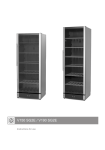
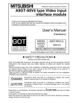
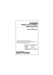
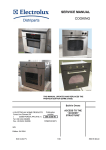
Packing List
[DESIGN PRECAUTIONS]
CAUTION
CAUTION
z
GT16 Multimedia Unit
User's Manual
Do not bunch the control wires or communication cables with the main circuit or power
wires, or lay them close to each other.
As a guide, separate the lines by a distance of at least 100mm (3.94 inches) otherwise
malfunctions may occur due to noise.
DANGER
z
z
z
z
Thank you for purchasing the GOT1000 Series.
Prior to use, please read both this manual and detailed
manual thoroughly to fully understand the product.
MODEL
GT16M-MMR-U
MODEL
CODE
1D7M87
Use this unit in the environment that satisfies the general specifications described in
the User's Manual for the GOT used.
Not doing so can cause an electric shock, fire, malfunction or product damage or
deterioration.
Do not drop the unit or subject it to string shock.
A unit damage may result.
When installing this unit to the GOT, fit it to the connection interface of the GOT and
tighten the mounting screws in the specified torque range.
Undertightening can cause a drop, failure or malfunction. Overtightening can cause a
drop, failure or malfunction due to screw or unit damage.
z
Before using this product, please read this manual and the relevant manuals introduced in this manual carefully and pay full attention to safety to handle the product
correctly.
The precautions given in this manual are concerned with this product.
In this manual, the safety precautions are ranked as "DANGER" and "CAUTION".
DANGER
Indicates that incorrect handling may cause hazardous
conditions, resulting in death or severe injury.
CAUTION
Indicates that incorrect handling may cause hazardous
conditions, resulting in medium or slight personal injury
or physical damage.
z
z
SH-080928ENG
(1D7MD3)
GT16 User's Manual (Basic Utility)
(Sold separately)
SH-080929ENG
(1D7MD4)
GOT1000 Series Connection Manual
(Microcomputer, MODBUS Products,
Peripherals) for GT Works3
(Sold separately)
SH-080871ENG
(1D7MC5)
GT Designer3 Version1 Screen Design Manual
(Functions)
(Sold separately)
SH-080867ENG
(1D7MC1)
*1
Video camera
Video
image
Relevant Manuals
*1: To store video files in the personal computer, the FTP server function of the
GOT and the multimedia interaction tool are required.
*2: Power on the GOT simultaneously with the video camera.
*3: Depending on the video camera type, noise from the power supply cable of the
video camera may cause malfunction of the GOT or a programmable controller.
In this case, attach the following line filter to the power supply line of the video
camera.
Recommended line filter: TDK ZHC2203-11 (or equivalent products)
To use the multimedia unit, set the communication settings.
For the settings and system configurations, refer to GOT1000 Series Connection
Manual (Microcomputer, MODBUS Products, Peripherals) for GT Works3.
For the multimedia function, refer to GT Designer3 Version1 Screen Design
Manual (Functions).
2. SPECIFICATIONS
The following shows the performance specifications of the multimedia unit.
The general specifications of the multimedia unit are the same as those of the
GOT.
For the general specifications of the GOT, refer to the User's Manual for the GOT
used.
Item
For relevant manuals, refer to the PDF manuals stored in the CD-ROM for the
drawing software used.
Color
Monochrome
Number of channels
Video input signal
Input
format
© 2008 MITSUBISHI ELECTRIC CORPORATION
Video input
section
Compliance with the EMC and Low Voltage
Directives
Always secure the cables connected to the unit, e.g. run them in conduits or clamp
them. Not doing so can cause unit or cable damage due to dangling, moved or
accidentally pulled cables or can cause a malfunction due to a cable contact fault.
z Do not hold the cable part when unplugging any cable connected to the unit.
Doing so can cause unit or cable damage or a malfunction due to a cable contact
fault.
z Always make sure to touch the grounded metal to discharge the electricity
charged in the body, etc., before touching the unit. Failure to do so may
cause a failure or malfunctions of the unit.
CF card in the
multimedia unit
GT16M-MMR
GT16 User's Manual (Hardware)
(Sold separately)
z
Note that the
CAUTION level may lead to a serious accident according to the
circumstances.
Always follow the precautions of both levels because they are important to personal safety.
Please save this manual to make it accessible when required and always forward it
to the end user.
CF card in the GOT
GOT
CAUTION
CAUTION
CAUTION
1
1
Do not mount not desmount
a module while the power is
supplied.
Exercise care to avoid foreign matter such as chips and wire offcuts entering the unit.
Not doing so can cause a fire, failure or malfunction.
Make sure to securely connect the cable to the connector of unit.
Incorrect connection may cause malfunctions.
Before starting cleaning, always shut off GOT power externally in all phases.
Not doing so can cause a unit failure or malfunction. Undertightening can cause the
GOT to drop, short circuit or malfunction.
Overtightening can cause a short circuit or malfunction due to the damage of the
screws or unit.
Do not disassemble or modify the unit and the CF card.
Doing so can cause a failure, malfunction, injury or fire.
Do not touch the conductive areas and electronic parts of this unit directly.
Doing so can cause a unit malfunction or failure.
1
Personal computer
Video file
(Ethernet)
Manual number
(Model code)
DANGER
z
Quantity
1
This user’s manual describes GT16 multimedia unit (hereinafter referred to as the
multimedia unit).
The following functions are available by mounting the multimedia unit on the
GT16
M.
• The GOT displays a video image taken by a video camera, or the GOT stores
the video image as a video file in a CF card and plays the file.
• When an error occurs, a video image taken 120 seconds before and after the
error (up to 240 seconds) can be stored as a video file in a CF card.
• With the Ethernet connection, the GOT sends a video file to the personal
computer using the FTP server function.
Manuals
Manual name
zSAFETY PRECAUTIONSz
(Always read these precautions before using this equipment.)
CAUTION
z Make sure to transport the GOT main unit and/or relevant unit(s) in the
manner they will not be exposed to the impact exceeding the impact
resistance described in the general specifications of the User's Manual for
the GOT used, as they are precision devices.
Failure to do so may cause the unit to fail.
Check if the unit operates correctly after transportation.
Detailed Manual
[STARTUP AND MAINTENANCE PRECAUTIONS]
Product
Multimedia unit
Mounting screw set (4 screws, 4
stickers)
Extension interface relay board
Cable clamp (for sound I/O)
GT16M-MMR
The following shows manuals relevant to this product.
DANGER
z
CAUTION
z Dispose of this product as industrial waste.
Be sure to shut off all phases of the external power supply used by the system before
wiring.
Failure to do so may result in an electric shock, product damage or malfunctions.
IB(NA)-0800432-E(1106)MEE
Model
1. OVERVIEW
[TRANSPORTATION PRECAUTIONS]
[WIRING PRECAUTIONS]
z
After unpacking the box, check that the following products are included.
When installing a CF card into this unit, insert it into the card slot of this unit until the
CF card eject button pops out.
Failure to do so may cause a malfunction due to poor contact.
Before inserting or removing a CF card into/from this unit, turn the CF card access
switch off.
Failure to do so may corrupt data on the CF card.
When removing a CF card from the GOT, support it by hand, as it may pop out. Failure
to do so may cause the CF card to drop from the unit, resulting in a damage or failure.
[DISPOSAL PRECAUTIONS]
Be sure to shut off all phases of the external power supply used by the system before
mounting or removing this unit to/from the GOT. Not doing so can cause a unit failure
or malfunction.
Before connecting the Bus connection cable to this unit, always shut off GOT power
and PLC CPU power externally in all phases.Not doing so can cause a malfunction.
CAUTION
z
z
z
[INSTALLATION PRECAUTIONS]
GT16M-MMR
z
To configure a system meeting the requirements of the EMC and Low Voltage
Directives when incorporating the Mitsubishi GOT (EMC and Low Voltage
Directives compliant) into other machinery or equipment, refer to "EMC AND LOW
VOLTAGE DIRECTIVES" of the General Description included with the GOT used.
The CE mark, indicating compliance with the EMC and Low Voltage Directives, is
printed on the rating plate of the GOT.
Compliance with the Radio Waves Act (South
Korea)
This product complies with the Radio Waves Act (South Korea).
Note the following when using the product in South Korea.
이 기기는 업무용 (A 급 ) 전자파적합기기로서 판매자 또는 사용자는 이 점을
주의하시기 바라며 , 가정외의 지역에서 사용하는 것을 목적으 로 합니다 .
(The product is for business use (Class A) and meets the electromagnetic
compatibility requirements.
The seller and the user must note the above point, and use the product in a place
except for home.)
Display size (dot)
Connector for external
connection
Applicable wire size
Number of channels
Sound input
Sound input signal
section
Connector for external
connection
Number of channels
Sound output
Sound output signal
section
Connector for external
connection
Slot
CF Card I/F
section
Mode
Number of channels
Ethernet I/F
Connector for external
section
connection
Data transfer method
File format
Video coding/decoding
Video file
format
Resolution/maximum
frame rate
3.3VDC
Internal current consumption
5.0VDC
Weight
Specifications
NTSC format, PAL format (interlaced format)
EIA format, CCIR format (interlaced format)
1 channel
IVp-p, 75 , composite signal
640x480
768x576*1
BNC connector
75 shielded coaxial cable al shield cable
1 channel
1 Vrms
3.5 stereo mini jack, straight type
1 channel
1 Vrms (Rated load 10k
)
3.5 stereo mini jack, straight type
Compact flash Slot (TYPE1) 1 channel
True-IDE mode
1 channel
RJ-45 jack
10BASE-T/100BASE-TX
3GP, MP4
MPEG-4 Part.2 SP@LV4
VGA/15fps, QVGA/30fps
0.51A
0.27A
0.28kg (0.61lb)
*1:Compatible with PAL and CCIR formats only.
3. PART NAMES AND EXTERNAL
DIMENSIONS
4. INSTALLATION PROCEDURE
4.1 Cable Connection
3.1 Multimedia Unit
11)
3)
1) Connect the cables of the sound I/O devices to the multimedia unit.
2) Attach the cable clamp to the unit.
Position the cable clamp band outside, and insert the cable clamp to section A
shown in the following figure until it clicks. For the band inserting direction, refer
to the arrow.
(The cable clamp is the RST-1NB manufactured by TAKEUCHI INDUSTRY CO.,
LTD.)
3) Put the cables of the sound I/O devices through the looped cable clamp band,
and pull the band to fix the cables.
GOT main unit
10)
5)
98 (3.86)
1)
12)
23
(0.91)
9
(0.35)
14
(0.55)
6)
11)
8)
4)
No.
26
(1.02)
8
(0.31)
44 (1.73)
35 (1.38)
32 (1.26)
46 (1.81)
9)
Dimensions
of X
33.5 (1.32)
32 .0 (1.26)
35 .0 (1.38)
37.0 (1.46)
GOT
15"
12.1"
10.4"
8.4"
Description
2)
Connector for video
input
Interface connector
3)
Extension connector Connector for connecting an extension unit
4)
CF card interface
1)
5)
6)
7)
8)
9)
10)
11)
12)
Removing multimedia unit
Remove the board fixing screws, and then remove the multimedia unit by
tilting
PULL so that the connector is not damaged. (Refer to 6).)
Cable clamp
(1) Removing cable clamp band
The cable clamp band can be removed after the cables are fixed.
Press the tab of the cable clamp upward using a screwdriver and others,
and pull out the band.
(2) Removing cables from multimedia unit
The cables of the sound I/O devices can be removed from the unit even if
the cables are fixed with the cable clamp.
Remove the cables by pressing the cable clamp from both directions
(arrow A).
Cable clamp
The installation procedure for the multimedia unit is explained using the GT1685.
A
1) Turn off the GOT.
2) Remove two extension unit covers of the GOT.
Unit : mm (inch)
86 (3.39)
111 (4.37)
Name
A
Precautions for connecting sound I/O devices
• Do not connect or disconnect the cables of the sound I/O sections during
sound input or output.
• Do not connect devices other than sound I/O devices to the sound I/O
sections of the multimedia unit.
4.2 Unit Installation
Dimensions of X when
mounted the GOT
2)
3)
Cable of the
external I/O device
24
(0.94)
X
7)
1)
2)
38 (1.50)
128 (5.04)
133 (5.24)
Warranty
Point
Connector for connecting a coaxial cable
Connector connected to the GOT
3) Connect the extension interface relay board to the extend I/F-2 on the GOT.
Remove the connector cover from the board.
4) Fit the multimedia unit in the GOT case.
Remove the connector cover.
5.1 Installation
1) Open the CF card cover, and turn off the CF card access switch of the unit.
3)
4)
5. CF CARD INSTALLATION/REMOVAL
PROCEDURE
Interface for inserting a CF card
Switch for enabling or disabling access to the CF card
CF card access
ON: CF card accessed
switch
OFF: CF card not accessed
CF card access LED LED lamp lit when the CF card is accessed
Terminal for connecting the cable of the sound input
Sound input terminal
device
Sound output
Terminal for connecting the cable of the sound output
terminal
device
Ethernet interface
Connector for Ethernet communication
Board fixing screw
Screw for fixing the extension interface relay board
Mounting screw
Screw for fixing the multimedia unit
Rating plate
-
21.5 (0.85)
3.2 Extension Interface Relay Board
64 (2.52)
5) Tighten four mounting screws with a torque of 0.36 to 0.48 N•m to fix the unit.
6) Tighten two board fixing screws with a torque of 0.36 to 0.48 N•m to fix the
board.
5)
6)
2) Insert a CF card into the CF card interface with the front side facing up.
3) Turn on the CF card access switch.
7) For mounting any extension unit on the multimedia unit, remove the connector
cover and the stickers.
For mounting no extension unit on the multimedia unit, cover over four mounting
screws with the accessory stickers to avoid static electricity.
Keep the connector cover fixed.
Keep all the stickers fixed.
Connector cover
5.2 Removal
1) Open the CF card cover.
Turn off the CF card access switch, and check that the CF card access LED
turns off.
(When the CF card access LED is off, the CF card can be removed even while
the GOT power is on.
Accessory sticker
41 (1.61)
Sticker
Unit : mm (inch)
2) Press the CF card eject button to pop out the CF card, and remove the card.
Accessory sticker
Mitsubishi will not be held liable for damage caused by factors found
not to be the cause of Mitsubishi; machine damage or lost profits
caused by faults in the Mitsubishi products; damage, secondary
damage, accident compensation caused by special factors
unpredictable by Mitsubishi; damages to products other than
Mitsubishi products; and to other duties.
For safe use
• This product has been manufactured as a general-purpose part for
general industries, and has not been designed or manufactured to
be incorporated in a device or system used in purposes related to
human life.
• Before using the product for special purposes such as nuclear
power, electric power, aerospace, medicine or passenger
movement vehicles, consult with Mitsubishi.
• This product has been manufactured under strict quality control.
However, when installing the product where major accidents or
losses could occur if the product fails, install appropriate backup or
failsafe functions in the system.
Country/Region Sales office/Tel
U.S.A
Mitsubishi Electric Automation Inc.
500 Corporate Woods Parkway Vernon Hills, IL 60061, U.S.A.
Tel : +1-847-478-2100
Brazil
MELCO-TEC Rep. Com.e Assessoria Tecnica Ltda.
Rua Correia Dias, 184, Edificio Paraiso Trade Center-8 andar
Paraiso, Sao Paulo, SP Brazil
Tel : +55-11-5908-8331
Germany
Mitsubishi Electric Europe B.V. German Branch
Gothaer Strasse 8 D-40880 Ratingen, GERMANY
Tel : +49-2102-486-0
U.K
Mitsubishi Electric Europe B.V. UK Branch
Travellers Lane, Hatfield, Hertfordshire., AL10 8XB, U.K.
Tel : +44-1707-276100
Italy
Mitsubishi Electric Europe B.V. Italian Branch
Centro Dir. Colleoni, Pal. Perseo-Ingr.2
Via Paracelso 12, I-20041 Agrate Brianza., Milano, Italy
Tel : +39-039-60531
Spain
Mitsubishi Electric Europe B.V. Spanish Branch
Carretera de Rubi 76-80,
E-08190 Sant Cugat del Valles, Barcelona, Spain
Tel : +34-93-565-3131
France
Mitsubishi Electric Europe B.V. French Branch
25, Boulevard des Bouvets, F-92741 Nanterre Cedex, France
Tel : +33-1-5568-5568
South Africa
Circuit Breaker Industries Ltd.
Private Bag 2016, ZA-1600 Isando, South Africa
Tel : +27-11-928-2000
Hong Kong
Mitsubishi Electric Automation (Hong Kong) Ltd.
10th Floor, Manulife Tower, 169 Electric
Road, North Point, Hong Kong
Tel : +852-2887-8870
China
Mitsubishi Electric Automation (China) Ltd.
4/F Zhi Fu Plazz, No.80 Xin Chang Road,
Shanghai 200003, China
Tel : +86-21-6120-0808
Taiwan
Setsuyo Enterprise Co., Ltd.
6F No.105 Wu-Kung 3rd.Rd, Wu-Ku Hsiang,
Taipei Hsine, Taiwan
Tel : +886-2-2299-2499
Korea
Mitsubishi Electric Automation Korea Co., Ltd.
1480-6, Gayang-dong, Gangseo-ku Seoul
157-200, Korea
Tel : +82-2-3660-9552
Singapore
Mitsubishi Electric Asia Pte, Ltd.
307 Alexandra Road #05-01/02,
Mitsubishi Electric Building, Singapore 159943
Tel : +65-6470-2460
Thailand
Mitsubishi Electric Automation (Thailand) Co., Ltd.
Bang-Chan Industrial Estate No.111 Moo 4, Serithai Rd,
T.Kannayao, A.Kannayao, Bangkok 10230 Thailand
Tel : +66-2-517-1326
Indonesia
P.T. Autoteknindo Sumber Makmur
Muara Karang Selatan, Block A/Utara
No.1 Kav. No.11 Kawasan Industri Pergudangan
Jakarta - Utara 14440, P.O.Box 5045 Jakarta, 11050 Indonesia
Tel : +62-21-6630833
India
Messung Systems Pvt, Ltd.
Electronic Sadan NO:III Unit No15, M.I.D.C Bhosari,
Pune-411026, India
Tel : +91-20-2712-3130
Australia
Mitsubishi Electric Australia Pty. Ltd.
348 Victoria Road, Rydalmere, N.S.W 2116, Australia
Tel : +61-2-9684-7777
HEAD OFFICE : TOKYO BUILDING, 2-7-3 MARUNOUCHI, CHIYODA-KU, TOKYO 100-8310, JAPAN
NAGOYA WORKS : 1-14, YADA-MINAMI 5-CHOME, HIGASHI-KU, NAGOYA, JAPAN
When exported from Japan, this manual does not require application to the Ministry
of Economy, Trade and Industry for service transaction permission.
Specifications subject to change without notice.
Printed in Japan, June 2011.