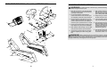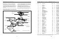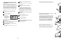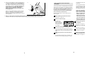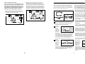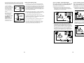
1
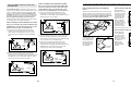
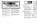
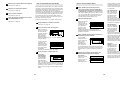
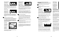
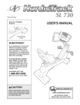
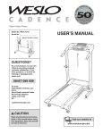
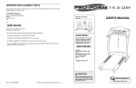
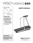
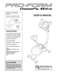
ORDERING REPLACEMENT PARTS
To order replacement parts, contact the ICON Health & Fitness, Ltd. office, or write:
ICON Health & Fitness, Ltd.
Unit 4
Revie Road Industrial Estate
Revie Road
Beeston
Leeds
LS11 8JG
UK
Class HC Fitness Product
Model No. NTEVEX99830
Serial No.
Tel:
08457 089 009
Fax: 0 (444) 113 387 7125
Serial Number
Decal
When ordering parts, please be prepared to give the following information:
• the MODEL NUMBER of the product (NTEVEX99830)
QUESTIONS?
• the NAME of the product (NordicTrack® SL 850 exercise cycle)
As a manufacturer, we are committed to providing complete
customer satisfaction. If you have
questions, or if there are missing
parts, please call:
• the SERIAL NUMBER of the product (see the front cover of this manual)
• the KEY NUMBER and DESCRIPTION of the part(s) (see page 25)
08457 089 009
Or write:
ICON Health & Fitness, Ltd.
Unit 4
Revie Road Industrial Estate
Revie Road
Beeston
Leeds
LS11 8JG
email: [email protected]
CAUTION
Read all precautions and instructions in this manual before using
this equipment. Keep this manual
for future reference.
Part No. 202611 R1003A
Printed in China © 2003 ICON Health & Fitness, Inc.
USER'S MANUAL
18
57
47
21
23
2
30
TABLE OF CONTENTS
78
83
33 96
49
1
33
28
24
50
76
61
28
92 90
22
46
89
83
45
83
75
87
71
20
70
38
71
59
98
98
8
83
51
51
72
71
69
74
37
57
83
84
75
36
95
75
5
64
68
44
48
57
84
33
77
90
34
68
63
35
32
57
33
91
85
29
88
25
63
67
39
97
31
88
IMPORTANT PRECAUTIONS . . . . . . . . . . . . . . . . . . . . . . . . . . . . . . . . . . . . . . . . . . . . . . . . . . . . . . . . . . . . .3
BEFORE YOU BEGIN . . . . . . . . . . . . . . . . . . . . . . . . . . . . . . . . . . . . . . . . . . . . . . . . . . . . . . . . . . . . . . . . . . .4
ASSEMBLY . . . . . . . . . . . . . . . . . . . . . . . . . . . . . . . . . . . . . . . . . . . . . . . . . . . . . . . . . . . . . . . . . . . . . . . . . . .5
HOW TO USE THE CHEST PULSE SENSOR . . . . . . . . . . . . . . . . . . . . . . . . . . . . . . . . . . . . . . . . . . . . . . . . .9
HOW TO OPERATE THE EXERCISE CYCLE . . . . . . . . . . . . . . . . . . . . . . . . . . . . . . . . . . . . . . . . . . . . . . . .11
MAINTENANCE AND TROUBLESHOOTING . . . . . . . . . . . . . . . . . . . . . . . . . . . . . . . . . . . . . . . . . . . . . . . . .23
EXERCISE GUIDELINES . . . . . . . . . . . . . . . . . . . . . . . . . . . . . . . . . . . . . . . . . . . . . . . . . . . . . . . . . . . . . . . .24
PART LIST . . . . . . . . . . . . . . . . . . . . . . . . . . . . . . . . . . . . . . . . . . . . . . . . . . . . . . . . . . . . . . . . . . . . . . . . . . .25
EXPLODED DRAWING . . . . . . . . . . . . . . . . . . . . . . . . . . . . . . . . . . . . . . . . . . . . . . . . . . . . . . . . . . . . . . . . .26
ORDERING REPLACEMENT PARTS . . . . . . . . . . . . . . . . . . . . . . . . . . . . . . . . . . . . . . . . . . . . . . . .Back Cover
50
97
51
57
43
40
94
41
51
3
57
14
13
53
17
55 56
16
53
55
19
53
55
15
55
19
19
56
54
56 54
NordicTrack is a registered trademark of ICON Health & Fitness, Inc.
2
27
56
54
54
19
EXPLODED DRAWING—Model No. NTEVEX99830
R1003A
WARNING:
To reduce the risk of serious injury, read the following important precautions before using the exercise cycle.
66
62
55
60
60
79
80
55
12
4
80
63
7
6
57
55 79
80
55
6
80
1. Read all instructions in this manual before
using the exercise cycle. Use the exercise
cycle only as described.
42
9
IMPORTANT PRECAUTIONS
7. Wear suitable clothing when using the
exercise cycle; do not wear loose clothing
that could become caught on the exercise
cycle. Always wear athletic shoes.
2. It is the responsibility of the owner to
ensure that all users of the exercise cycle
are adequately informed of all precautions.
8. Always keep your back straight when using
the exercise cycle. Do not arch your back.
3. Use the exercise cycle indoors on a level
surface. Keep the exercise cycle away from
moisture and dust. Place a mat under the
exercise cycle to protect the floor or carpet.
9. If you feel pain or dizziness whilst exercising, stop immediately and cool down.
10. The pulse sensors are not medical devices.
Various factors, including the user's movement, may affect the accuracy of heart rate
readings. The pulse sensors are intended
only as exercise aids in determining heart
rate trends in general.
4. Inspect and properly tighten all parts regularly. Replace any worn parts immediately.
82
57
86
57
5. Keep children under the age of 12 and pets
away from the exercise cycle at all times.
73
57
52 51
10
51
81
11
27
58
WARNING:
Before beginning this or any exercise program, consult your physician. This
is especially important for persons over the age of 35 or persons with pre-existing health problems.
Read all instructions before using. ICON assumes no responsibility for personal injury or property
damage sustained by or through the use of this product.
58
57
83
11. The exercise cycle is intended for in-home
use only. Do not use the exercise cycle in a
commercial, rental, or institutional setting.
6. The exercise cycle should not be used by
persons weighing more than 115 kg (250
lbs).
58
57
83
93
65
26
57
57
65
93
65
26
3
PART LIST—Model No. NTEVEX99830
BEFORE YOU BEGIN
reading this manual, please call our Customer Service
Department at 08457 089 009. To help us assist you,
please mention the product model number and serial
number when calling. The model number is
NTEVEX99830. The serial number can be found on a
decal attached to the exercise cycle (see the front
cover of this manual for the location of the decal).
Congratulations for selecting the new NordicTrack®
SL 850 exercise cycle. Cycling is one of the most
effective exercises for increasing cardiovascular fitness, building endurance, and toning the entire body.
The NordicTrack® SL 850 exercise cycle offers an
impressive array of features designed to let you enjoy
this healthful exercise in the comfort and privacy of
your home.
Before reading further, please familiarise yourself with
the parts that are labeled in the drawing below.
For your benefit, read this manual carefully before
using the exercise cycle. If you have questions after
Water Bottle Holder*
Fan
Bookrack
Console
FRONT
Seat
Seat Knob
Pedal/Strap
Backrest
Wheel
Handgrip Pulse Sensor
Handlebar
RIGHT SIDE
REAR
Leveling Foot
*No water bottle is included.
Key No. Qty.
1
2
3
4
5
6
7
8
9
10
11
12
13
14
15
16
17
18
19
20
21
22
23
24
25
26
27
28
29
30
31
32
33
34
35
36
37
38
39
40
41
42
43
44
45
46
47
48
49
50
51
1
1
1
1
1
2
1
1
1
1
1
1
1
1
1
1
2
1
4
1
1
1
1
1
1
1
1
2
1
1
1
2
4
1
1
1
1
1
1
1
1
1
1
1
1
1
1
1
1
2
12
Description
Key No. Qty.
Frame
Upright
Pulse Wire
Console
Seat Rail
Pulse Sensor
Seat Frame
Seat Rail Endcap
Seat
Seat Knob
Seat Carriage
Seat Frame Endcap
Front Stabiliser Cover
Rear Stabiliser Cover
Front Stabiliser
Rear Stabiliser
Wheel
Right Pedal Strap
Leveling Foot
Generator
Right Pedal
Left Pedal
Right Crank Arm
Left Crank Arm
Left Pedal Strap
Left Side Shield
Right Side Shield
Snap Ring
Pulley
Magnet
Crank Assembly
Pulley Spacer
Crank Bearing
Flywheel
“C” Magnet
Resistance Cable
Spring
Resistance Motor
Idler Arm
Control Board
Control Bracket
Backrest Frame
Wire Harness
Flywheel Bracket
Clamp
Reed Switch/Wire
Drive Belt
Flywheel Axle
M10 x 82mm Bolt
Flange Screw
Standoff
52
53
54
55
56
57
58
59
60
61
62
63
64
65
66
67
68
69
70
71
72
73
74
75
76
77
78
79
80
81
82
83
84
85
86
87
88
89
90
91
92
93
94
95
96
97
98
#
#
#
#
1
2
8
12
8
20
4
2
4
1
1
5
4
6
1
1
4
2
1
6
1
1
4
6
1
3
2
4
8
1
2
13
2
1
1
1
2
1
3
1
1
2
2
1
1
4
2
3
1
1
1
R1003A
Description
Seat Carriage Endcap
Bolt Set
M8 x 40mm Button Screw
M8 Split Washer
M4 x 38mm Screw
M4 x 16mm Screw
Carriage Bushing
M6 x 50mm Bolt
M8 Washer
M10 Washer
Backrest
M10 Nylon Locknut
M5 Nylon Locknut
M4 x 25mm Screw
Backrest Frame Endcap
Idler Bolt
M8 x 14mm Tapered Bolt
M6 Nut
Frame RJ14 Outlet
M5 Washer
Frame RJ14 Bracket
Carriage RJ14 Bracket
M5 x 16mm Bolt
M5 x 16mm Round Head Screw
M10 x 43mm Bolt
M8 x 35mm Screw
M10 x 110mm Button Screw
M8 x 25mm Button Screw
1/4” x 16mm Button Screw
Carriage RJ14 Outlet
M10 x 52mm Button Bolt
M6 Nylon Locknut
Bumper
“J” Bolt Bushing
RJ14 Cable
M6 x 52mm Bolt
M10 Split Washer
M8 Nylon Locknut
M8 Nylon Jam Nut
M6 x 45mm Bolt
M10 Flange Nut
M5 x 25mm Round Head Screw
M4 Washer
M4 Push Nut
Thrust Washer
M6 x 18mm Bolt
M6 x 18mm Round Head Screw
Hex Key
User’s Manual
Chest Strap
Sensor Unit
Note: “#” indicates a non-illustrated part. Specifications are subject to change without notice. See the back cover
of this manual for information about ordering replacement parts.
4
25
EXERCISE GUIDELINES
ASSEMBLY
Fat Burning
WARNING:
To burn fat effectively, you must exercise at a relatively low intensity level for a sustained period of time.
During the first few minutes of exercise, your body
uses easily accessible carbohydrate calories for energy. Only after the first few minutes of exercise does
your body begin to use stored fat calories for energy. If
your goal is to burn fat, adjust the intensity of your
exercise until your heart rate is near the lowest number or the middle number in your training zone as you
exercise.
• Before beginning this or any exercise program, consult your physician. This is especially important for individuals over the
age of 35 or individuals with pre-existing
health problems.
• The pulse sensors are not medical
devices. Various factors, including the
user's movement, may affect the accuracy
of heart rate readings. The pulse sensors
are intended only as exercise aids in determining heart rate trends in general.
Assembly requires two persons. Place all parts of the exercise cycle in a cleared area and remove the packing
materials. Do not dispose of the packing materials until assembly is completed.
Assembly requires the included tools and your own adjustable spanner
.
Use the drawings below to identify the small parts used in assembly. The number in parenthesis below each
drawing refers to the key number of the part, from the PART LIST on page 25. The second number refers to the
quantity needed for assembly. Note: Some small parts may have been pre-assembled for shipping. If a part
is not in the parts bag, check to see if it has been pre-assembled.
Aerobic Exercise
If your goal is to strengthen your cardiovascular system, your exercise must be “aerobic.” Aerobic exercise
is activity that requires large amounts of oxygen for
prolonged periods of time. This increases the demand
on the heart to pump blood to the muscles, and on the
lungs to oxygenate the blood. For aerobic exercise,
adjust the intensity of your exercise until your heart
rate is near the highest number in your training zone.
The following guidelines will help you to plan your
exercise program. Remember that proper nutrition and
adequate rest are essential for successful results.
EXERCISE INTENSITY
Whether your goal is to burn fat or to strengthen your
cardiovascular system, the key to achieving the
desired results is to exercise with the proper intensity.
The proper intensity level can be found by using your
heart rate as a guide. The chart below shows recommended heart rates for fat burning, maximum fat burning, and cardiovascular (aerobic) exercise.
WORKOUT GUIDELINES
M8 Split
Washer (55)–12
M4 x 16mm
Screw (57)–4
M10 Split
Washer (88)–2
M8 Washer
(60)–4
1/4” x 16mm Button
Screw (80)–8
M10 Nylon
Locknut (63)–2
M8 x 40mm Button
Screw (54)–8
M8 x 25mm Button
Screw (79)–4
Each workout should include the following three parts:
A warm-up, consisting of 5 to 10 minutes of stretching
and light exercise. A proper warm-up increases your
body temperature, heart rate, and circulation in preparation for exercise.
Training zone exercise, consisting of 20 to 30 minutes of exercising with your heart rate in your training
zone. (During the first few weeks of your exercise program, do not keep your heart rate in your training
zone for longer than 20 minutes.)
A cool-down, with 5 to 10 minutes of stretching. This
will increase the flexibility of your muscles and will
help to prevent post-exercise problems.
To find the proper heart rate for you, first find your age
at the bottom of the chart (ages are rounded off to the
nearest ten years). Next, find the three numbers above
your age; the three numbers are your “training zone.”
The lowest number is the recommended heart rate for
fat burning; the middle number is the recommended
heart rate for maximum fat burning; and the highest
number is the heart rate for aerobic exercise.
M10 x 52mm Button Bolt (82)–2
M10 x 110mm Button Screw (78)–2
1. Identify the Front Stabiliser (15). Whilst another person
lifts the front of the Frame (1), attach the Front
Stabiliser to the Frame with four M8 x 40mm Button
Screws (54) and four M8 Split Washers (55).
1
1
EXERCISE FREQUENCY
To maintain or improve your condition, plan three workouts each week, with at least one day of rest between
workouts. After a few months of regular exercise, you
may complete up to five workouts each week, if
desired. The key to success is make exercise a regular and enjoyable part of your everyday life.
15
55
55
54
24
5
54
2. Whilst another person lifts the rear of the Frame (1),
attach the Rear Stabiliser (16) to the Frame with four
M8 x 40mm Button Screws (54) and four M8 Split
Washers (55).
2
MAINTENANCE AND TROUBLESHOOTING
Inspect and properly tighten all parts of the exercise
cycle regularly. To clean the exercise cycle, use a
soft, damp cloth. Keep liquids away from the console
and keep the console out of direct sunlight.
1
16
Locate the Reed Switch (46). Turn the Right Crank
Arm (23) until the Magnet (30) is aligned with the
Reed Switch. Loosen, but do not remove, the indicated M4 x 16mm Screw (57). Slide the Reed Switch
slightly closer to or away from the Magnet. Then,
retighten the Screw. Turn the Right Crank Arm for a
moment. Repeat until the console displays correct
feedback. When the Reed Switch is correctly adjusted, reattach the Right Side Shield (27) and the Right
Pedal (21).
HOW TO ADJUST THE REED SWITCH
If the console does not display correct feedback, the
reed switch should be adjusted. To adjust the reed
switch, the Right Side Shield (27) must first be
removed. Remove the indicated M4 x 25mm Screws
(65) from the Left Side Shield (26).
55
55
54
Front View
54
3. Have another person hold the Upright (2) in the position shown. See the inset drawing. Locate the wire
extending from the bottom of the Upright. Tie the wire
around the ends of the Wire Harness (43) and the
Pulse Wire (3) as shown. Carefully pull the wire up
through the Upright until the Wire Harness and the
Pulse Wire are extending from the top of the Upright.
Untie the wire and discard it. Carefully pull the ends
of the Wire Harness and the Pulse Wire to remove
any slack.
3
43
3
27
46
65
26
23
2
Do not pinch the
Wire Harness
(43) or the Pulse
Wire (3) during
this step.
88
Insert the Upright (2) into the Frame (1). Be careful to
avoid pinching the Wire Harness (43) or the Pulse
Wire (3). Attach the Upright with two M10 x 110mm
Button Screws (78) and two M10 Split Washers (88).
30 57
65
78
1
88
Wire
HOW TO ADJUST THE DRIVE BELT
Next, remove the indicated M5 x 25mm Screw (93)
and M4 x 16mm Screws (57) from the Right Side
Shield (27). Using an adjustable wrench, turn the
Right Pedal (21) counterclockwise and remove it. Turn
the Right Crank Arm (23) so that it is pointing toward
the front of the exercise cycle, and then slide off the
Right Side Shield.
If you can feel the pedals slip whilst you are pedaling,
even when the resistance is adjusted to the highest
level, the Drive Belt (47) may need to be adjusted. To
adjust the Drive Belt, you must first remove the right
side shield. See HOW TO ADJUST THE REED
SWITCH at the left and remove the right side shield.
43
3
4. Have another person hold the Console (4) near the
Upright (2).
4
4
6
23
21
Connect the Wire Harness (43) to the wire harness on
the Console (4). Connect the Pulse Wire (3) to the
pulse wire on the Console. Next, locate the two ground
wires that are connected with a screw to the Upright
(2). Connect the ground wires to the two smallest wires
on the Console.
Carefully insert all excess wiring down into the Upright
(2). Attach the Console (4) to the Upright with four M4
x 16mm Screws (57). Be careful to avoid pinching
the wires.
Next, turn the
indicated M10
Nylon Locknut
(63) until the
Drive Belt (47) is
properly tightened. Then, reattach the right
side shield.
57
3
47
63
43
27
93
57
PULSE SENSOR TROUBLESHOOTING
57
If the chest pulse sensor does not function properly,
see CHEST PULSE SENSOR TROUBLESHOOTING
on pages 9 and 10. If the handgrip pulse sensor does
not function properly, see step 5 on page 14.
Ground Wires
2
Do not pinch
the wires
during this step.
23
6
HOW TO USE PROGRAMS DIRECTLY FROM
OUR WEB SITE
7
Begin pedaling to activate the console.
8
See step 1 on page 13.
9
To select the
iFIT.com mode,
press the iFIT.com
button. The indicator above the button will light.
Go to your computer and start an internet
connection.
4
Start your Web browser, if necessary, and go
to our Web site at www.iFIT.com.
5
Follow the desired links on our Web site to
select a program.
9
Return to the exercise cycle and begin
pedaling.
Measure your heart rate if desired.
See step 5 on page 14.
10 Turn on the fan if desired.
See step 6 on page 14.
11
7
60
60
Monitor your progress with the matrix and the
two displays.
See step 4 on page 13.
Select the iFIT.com mode.
3
5
When the on-screen countdown ends, the program will begin. The program will function in
almost the same way as a resistance and pace
program (see step 3 on page 15). However, an
electronic “chirping” sound will alert you when the
resistance setting and/or the target pace setting is
about to change.
Follow the steps below to use a program from our
Web site.
2
5. Attach the Seat (9) to the Seat Frame (7) with four 1/4”
x 16mm Button Screws (80) and four M8 Washers (60).
When you start the program, an on-screen countdown will begin.
Our Web site at www.iFIT.com allows you to play
iFIT.com audio and video programs directly from the
internet. To use programs from our Web site, the exercise cycle must be connected to your home computer.
See HOW TO CONNECT YOUR COMPUTER on
page 19. In addition, you must have an internet connection and an internet service provider. A list of specific system requirements is found on our Web site.
1
Follow the on-line instructions to start the
program.
When you are finished exercising, the console
will automatically turn off.
6. Pull the Seat Knob (10) and slide the Seat Carriage
toward the rear of the Seat Rail (5).
80
6
63
Have another person hold the Seat Frame (7) near the
Seat Carriage (11). Locate the two pulse wires extending from the Seat Frame. Connect each pulse wire to
the pulse wire of the same color in the Seat Carriage.
Insert the excess wiring up into the Seat Frame, and
set the Seat Frame on the Seat Carriage. Attach the
Seat Frame with two M10 x 52mm Button Bolts (82)
and two M10 Nylon Locknuts (63). Be careful to
avoid damaging the pulse wires with the Bolts.
7
Pulse Wires
82
10
11
5
See step 7 on page 14.
7. Attach the Backrest (62) to the Backrest Frame (42)
with four 1/4” x 16mm Button Screws (80).
Read and follow the on-line instructions for using
a program.
7
62
Slide the Backrest Frame (42) onto the Seat Frame
(7). Attach the Backrest Frame with four M8 x 25mm
Button Screws (79) and four M8 Split Washers (55).
42
55
79
55
55
79
80
7
22
7
8. Identify the Left Pedal (22), which is marked with an
“L.” Using an adjustable wrench, firmly tighten the
Left Pedal counterclockwise into the Left Crank Arm
(24). Tighten the Right Pedal (not shown) clockwise
into the Right Crank Arm. Important: Tighten both
Pedals as firmly as possible. After using the
exercise cycle for one week, retighten the
Pedals. For best performance, the Pedals must
be kept tightened.
8
your workout. Simply follow your personal trainer’s
instructions.
HOW TO USE IFIT.COM CD AND VIDEO
PROGRAMS
25
22
24
Identify the Left Pedal Strap (25), which is marked
with an “L.” Attach the Left Pedal Strap to the Left
Pedal (22), and adjust it to the desired position.
Attach and adjust the Right Pedal Strap (not shown)
in the same way.
9. Make sure that all parts are properly tightened before you use the exercise cycle. Note: After assembly is
completed, some extra parts may be left over. Place a mat beneath the exercise cycle to protect the floor.
The program will function in almost the same way
as a resistance and pace program (see step 3 on
page 15). However, an electronic “chirping” sound
will alert you when the resistance setting and/or
the target pace setting is about to change.
To use iFIT.com CDs or videocassettes, the exercise
cycle must be connected to your portable CD player,
portable stereo, home stereo, computer with CD player, or VCR. See HOW TO CONNECT YOUR CD
PLAYER, VCR, OR COMPUTER on pages 18 to 20.
To purchase iFIT.com CDs and videocassettes,
visit our Web site at www.iFIT.com.
Note: If the resistance of the exercise cycle
and/or the target pace setting does not change
when a “chirp” is heard:
Follow the steps below to use an iFIT.com CD or
video program.
1
• Make sure that the indicator above the
iFIT.com button is lit.
• Adjust the volume of your CD player or VCR.
If the volume is too high or too low, the console may not detect the program signals.
Begin pedaling to activate the console.
See step 1 on page 13.
2
• Make sure that the audio cable is properly
connected and that it is fully plugged in.
Select the iFIT.com mode.
To select the
iFIT.com mode,
press the iFIT.com
button. The indicator above the button will light.
3
4
5
See step 4 on page 13.
6
Insert the iFIT.com CD or videocassette.
Measure your heart rate if desired.
See step 5 on page 14.
If you are using an iFIT.com CD, insert the CD
into your CD player. If you are using an iFIT.com
videocassette, insert the videocassette into your
VCR.
7
Press the play button on your CD player or
VCR.
8
Turn on the fan if desired.
See step 6 on page 14.
When you are finished exercising, the console
will automatically turn off.
See step 7 on page 14.
A moment after the play button is pressed, your
personal trainer will begin guiding you through
8
Monitor your progress with the matrix and the
two displays.
21
HOW TO CONNECT YOUR VCR
B. Plug one end of the audio cable into the jack
beneath the console. Plug the other end of the
audio cable into the adaptor. Plug the adaptor into
an RCA Y-adaptor (available at electronics stores).
Next, remove the wire that is currently plugged into
the AUDIO OUT jack on your VCR and plug the
wire into the unused side of the Y-adaptor. Plug the
Y-adaptor into the AUDIO OUT jack on your VCR.
Note: If your VCR has an unused AUDIO OUT jack,
see instruction A below. If the AUDIO OUT jack is
being used, see instruction B. If you have a TV
with a built-in VCR, see instruction B. If your VCR
is connected to your home stereo, see HOW TO
CONNECT YOUR HOME STEREO on page 19.
A. Plug one end of the audio cable into the jack
beneath the console. Plug the other end of the
audio cable into the adaptor. Plug the adaptor into
the AUDIO OUT jack on your VCR.
A
B
HOW TO USE THE CHEST PULSE SENSOR
HOW TO PUT ON THE CHEST PULSE SENSOR
CHEST PULSE SENSOR TROUBLESHOOTING
The chest pulse sensor consists of two components:
the chest strap and the sensor unit. Follow the steps
below to put on the chest pulse sensor.
If the chest pulse sensor does not function properly, or if the displayed heart rate is excessively high
or low, try the troubleshooting steps below.
Chest Strap
RF OUT
CH
3 4
OUT
RCA Y-adaptor
ANT. IN
• Make sure that you are wearing the chest pulse sensor as described at the left. If the chest pulse sensor
does not function when positioned as described,
move it slightly lower or higher on your chest.
ANT. IN
VIDEO AUDIO
IN
• Each time you use the chest pulse sensor, use
saline solution such as saliva or contact lens solution to wet the two electrode areas on the sensor
unit (see the drawing below). If heart rate readings
do not appear until you begin perspiring, re-wet the
electrode areas.
Tab
VIDEO AUDIO
IN
RF OUT
CH
3 4
OUT
Adaptor
AUDIO OUT
RIGHT
LEFT
Audio Wire removed from
Cable AUDIO OUT jack
Adaptor
Sensor Unit
1
Audio Cable
2
3
20
Buckle Sensor
Unit
• Make sure that you are within arm’s length of the
console. For the console to display heart rate
readings, the user must be within arm’s length of
the console.
See the inset drawing above. Insert the tab on
one end of the chest strap through one end of the
sensor unit. Press the end of the sensor unit
under the buckle on the chest strap.
• If you wear the chest pulse sensor and hold the
handgrip pulse sensor at the same time, the console
may not display your heart rate accurately.
Wrap the
chest pulse
sensor
around
Logo
your chest.
Attach the
free end of
the chest
strap to the
sensor unit as described above. Adjust the length
of the chest strap, if necessary. The chest pulse
sensor should be under your clothes, against
your skin, and as high under the pectoral muscles or breasts as is comfortable. Make sure that
the logo is right-side-up and facing forward.
• The chest pulse sensor is designed to work with
people who have normal heart rhythms. Heart rate
reading problems may be caused by medical conditions such as premature ventricular contractions
(pvcs), tachycardia bursts, and arrhythmia.
• The operation of the chest pulse sensor can be
affected by magnetic interference caused by high
power lines or other sources. If it is suspected that
magnetic interference may be causing a problem,
try relocating your exercise equipment.
• If the chest pulse sensor still does not function properly, test the chest pulse sensor in the following way:
Pull the
sensor unit
Electrode Areas
away from
your body
a few inches and
locate the
two electrode areas on the inner side. Using a saline
solution such as saliva or contact lens solution,
wet both electrode areas. Return the sensor unit
to a position against your chest.
Hold the chest
pulse sensor
Electrode Areas
and place your
thumbs over
the electrode
areas as
shown. Next,
hold the chest
pulse sensor near the console. Whilst holding one
thumb stationary, begin tapping the other thumb
against the electrode area at a rate of about one tap
per second. Check the heart rate reading on the
console.
9
• If the chest pulse sensor does not function properly
after you have followed all of the above instructions,
the battery should be replaced in the following way:
Locate the battery
cover on the back of
the sensor unit. Insert
a coin into the slot in
the cover, turn the
cover counterclockwise, and remove the
cover.
Remove the old battery and insert a
new CR 2032 battery. Make sure that
the battery is
turned so the writing is on top.
Replace the battery
cover and turn it
clockwise to close it.
CHEST PULSE SENSOR CARE
HOW TO CONNECT YOUR HOME STEREO
HOW TO CONNECT YOUR COMPUTER
• Thoroughly dry the chest pulse sensor after each
use. The chest pulse sensor is activated when the
electrode areas are wetted and the chest pulse sensor is put on; the chest pulse sensor shuts off when
it is removed and the electrode areas are dried. If
the chest pulse sensor is not dried after each use, it
may remain activated longer than necessary, draining the battery prematurely.
Note: If your stereo has an unused LINE OUT jack,
see instruction A below. If the LINE OUT jack is
being used, see instruction B.
Note: If your computer has a 3.5mm LINE OUT
jack, see instruction A. If your computer has only a
PHONES jack, see instruction B.
A. Plug one end of the audio cable into the jack
beneath the console. Plug the other end of the
audio cable into the adaptor. Plug the adaptor into
the LINE OUT jack on your stereo.
A. Plug one end of the audio cable into the jack
beneath the console. Plug the other end of the audio
cable into the LINE OUT jack on your computer.
• Store the chest pulse sensor in a warm, dry place.
Do not store the chest pulse sensor in a plastic bag
or other container that may trap moisture.
A
A
CD
VCR
Amp
• Do not expose the chest pulse sensor to direct
sunlight for extended periods of time. Do not expose
the chest pulse sensor to temperatures above 50° C
(122° F) or below -10° C (14° F).
CR 2032
Battery
LINE OUT
Audio
Cable
LINE OUT
Adaptor
Audio Cable
• Do not excessively bend or stretch the sensor unit
when using or storing the chest pulse sensor.
• Clean the sensor unit using a damp cloth—never
use alcohol, abrasives, or chemicals. The chest
strap may be hand washed and air dried.
LINE OUT
B. Plug one end of the audio cable into the jack
beneath the console. Plug the other end of the
audio cable into the splitter. Plug the splitter into the
PHONES jack on your computer. Plug your headphones or speakers into the other side of the splitter.
B. Plug one end of the audio cable into the jack
beneath the console. Plug the other end of the
audio cable into the adaptor. Plug the adaptor into
an RCA Y-adaptor (available at electronics stores).
Next, remove the wire that is currently plugged into
the LINE OUT jack on your stereo and plug the
wire into the unused side of the Y-adaptor. Plug the
Y-adaptor into the LINE OUT jack on your stereo.
B
B
PHONES
CD
Audio Cable
Splitter
VCR
Amp
Audio
Cable
Headphones/Speakers
LINE OUT
RCA
Y-adaptor
Adaptor
Wire removed from
LINE OUT jack
10
19
HOW TO CONNECT YOUR PORTABLE STEREO
HOW TO CONNECT YOUR CD PLAYER, VCR,
OR COMPUTER
To use iFIT.com CDs, the exercise cycle must be connected to your portable CD player, portable stereo, home
stereo, or computer with CD player. See pages 18 and
19 for connecting instructions. To use iFIT.com videocassettes, the exercise cycle must be connected to your
VCR. See page 20 for connecting instructions. To use
iFIT.com programs directly from our Web site, the
exercise cycle must be connected to your home computer. See page 19 for connecting instructions.
Note: If your stereo has an RCA-type AUDIO OUT
jack, see instruction A below. If your stereo has a
3.5mm LINE OUT jack, see instruction B. If your
stereo has only a PHONES jack, see instruction C.
A. Plug one end of the audio cable into the jack
beneath the console. Plug the other end of the
audio cable into the adaptor. Plug the adaptor into an
AUDIO OUT jack on your stereo.
HOW TO OPERATE THE EXERCISE CYCLE
HOW TO MOVE AND LEVEL THE EXERCISE
CYCLE
Stand in back of the exercise cycle, and lift the exercise cycle until it can be moved on the front wheels.
Move the exercise cycle to the desired location and
carefully lower it. Due to the weight of the exercise
cycle, use extreme caution whilst moving it.
A, B
HOW TO CONNECT YOUR PORTABLE CD PLAYER
AUDIO OUT
RIGHT
LEFT
Note: If your CD player has separate LINE OUT and
PHONES jacks, see instruction A below. If your CD
player has only one jack, see instruction B.
A. Plug one end of the audio cable into the jack
beneath the console. Plug the other end of the
audio cable into the LINE OUT jack on your CD
player. Plug your headphones into the PHONES
jack.
A
PHONES LINE OUT
LINE OUT
PHONES
Headphones
Audio
Cable
Wheel
Adaptor
HOW TO ADJUST THE SEAT
The seat can be
adjusted to the posiSeat Seat
tion that is the most
Knob
comfortable for you.
To adjust the seat,
pull the seat knob,
slide the seat forward or backward,
and then release
the seat knob. Move
the seat forward or
backward slightly
until the pin on the
seat knob snaps into one of the holes in the seat rail.
HOW TO ADJUST THE PEDAL STRAPS
Audio Cable
B. See the drawing above. Plug one end of the audio
cable into the jack beneath the console. Plug the
other end of the audio cable into the LINE OUT jack
on your stereo. Do not use the adaptor.
C. Plug one end of the audio cable into the jack
beneath the console. Plug the other end of the
audio cable into the splitter. Plug the splitter into the
PHONES jack on your stereo. Plug your headphones into the other side of the splitter.
If the exercise cycle
rocks slightly during
use, turn the leveling feet under the
rear stabiliser until
the rocking motion
is eliminated.
Leveling
Foot
The pedal straps
can be adjusted to
the position that is
the most comfortable for you. Press
the tabs on the pedals, adjust the
straps to the
desired position,
and then release
the tabs.
C
B. Plug one end of the audio cable into the jack
beneath the console. Plug the other end of the
audio cable into the splitter. Plug the splitter into the
PHONES jack on your CD player. Plug your headphones into the other side of the splitter.
PHONES
Audio
Cable Splitter
B
Headphones
PHONES
PHONES
Audio
Cable
Splitter
Headphones
18
11
Pedal
Strap
Tab
CONSOLE DIAGRAM
Left Display
Matrix
If you have
selected heart
rate program 2,
the letters “PLS”
and the current
target heart rate
setting will flash in
the left display. Press the + or – button repeatedly to change the target heart rate setting, if
desired. The target heart rate setting can be from
70 to 170 beats per minute.
Training Zone Bar
4
The advanced console offers a selection of features
designed to make your workouts more enjoyable and
effective. When the manual mode of the console is
selected, the resistance of the exercise cycle can be
changed with the touch of a button. As you exercise,
the console will provide continuous exercise feedback.
You can even measure your heart rate using the handgrip pulse sensor or the chest pulse sensor.
The console also offers six resistance and pace programs. Each program automatically changes the resistance of the exercise cycle and prompts you to
increase or decrease your pace as it guides you
through an effective workout.
In addition, the console features two heart rate programs that automatically change the resistance of the
exercise cycle and prompt you to vary your pace to
keep your heart rate near a target heart rate as you
exercise.
The console also features iFIT.com interactive technology. Having iFIT.com interactive technology is like having a personal trainer in your home. Using the included
audio cable, you can connect the exercise cycle to your
home stereo, portable stereo, computer, or VCR and
play special iFIT.com CD and video programs (iFIT.com
CDs and videocassettes are available separately).
iFIT.com CD and video programs automatically control
the resistance of the exercise cycle and prompt you to
vary your pace as a personal trainer coaches you
through every step of your workout. High-energy music
provides added motivation. To purchase iFIT.com
CDs and videocassettes, visit our Web site at
www.iFIT.com.
With the exercise cycle connected to your computer,
you can also go to our Web site at www.iFIT.com and
access programs directly from the internet. Explore
www.iFIT.com for more information.
Hold the handgrip pulse sensor.
To use a heart rate program, you must wear the
chest pulse sensor (see page 9) or use the handgrip pulse sensor (see step 5 on page 14). If you
use the handgrip pulse sensor, it is not necessary to hold the handgrips continuously during
the program. However, you should hold the
handgrips frequently for the program to operate
properly. Each time you hold the handgrips,
keep your hands on the metal contacts for at
least 30 seconds. Note: When you are not holding the handgrips, the letters “PLS” will appear in
the right display instead of your heart rate.
Note: If there is a sheet of clear plastic on the face of the console, remove it before using the console.
FEATURES OF THE CONSOLE
the handgrip pulse
a
sensor, the console will periodically compare your
heart rate to the
target heart rate
setting; if necesb
sary, an indicator
in the bar will then
flash to prompt you
to increase or
decrease your
pace to bring your
heart rate closer to the target heart rate setting. If
an indicator to the right of the lit indicators is
flashing (see drawing a), increase your pace. If
an indicator to the left of any lit indicator is flashing (see drawing b), decrease your pace. When
no indicator is flashing, your heart rate is near
the target heart rate setting. Important: The target heart rate settings are intended only to
provide motivation. Your actual heart rate
may be slower than the target heart rate settings. Make sure to exercise at a pace that is
comfortable for you.
5
The program will continue until the resistance setting for the last segment is shown in the Current
Segment column of the matrix and no time
remains in the program.
Press the Program Start button or begin
pedaling to start the program.
Heart rate program 1 consists of 20 one-minute
segments. One resistance setting and one target
heart rate setting are programmed for each segment. (The same resistance setting and/or target
heart rate setting may be programmed for two or
more consecutive segments.) During the program, the resistance of the exercise cycle will
periodically change. Heart rate program 2 is 40
minutes long (you may choose to use only part of
the program). The same resistance setting and
target heart rate setting are programmed for the
entire program.
Note: Heart rate programs cannot be stopped and
then restarted. If you stop pedaling for several
seconds, the program will end.
6
See step 4 on page 13.
7
Turn on the fan if desired.
See step 6 on page 14.
As you exercise, the Training Zone bar will help
you to keep your heart rate near the target heart
rate setting for the current segment. The lit indicators in the bar will show your actual pace.
Whilst you wear the chest pulse sensor or hold
12
Monitor your progress with the two displays.
8
When the program is finished, the console
will automatically turn off.
See step 7 on page 14.
17
4
Monitor your progress with the two displays.
HOW TO USE HEART RATE PROGRAMS
track representing 1/4 mile. As you exercise, the
indicators around the track will light in succession
until the entire track is lit. The track will then
darken and the indicators will again begin to light
in succession.
HOW TO USE THE MANUAL MODE
See step 4 on page 13.
5
Each heart rate program helps you to keep your heart
rate near a certain percentage of your maximum heart
rate during your workout. (Your maximum heart rate is
estimated by subtracting your age from 220. For
example, if you are 30 years old, your maximum heart
rate is 190.) Heart rate program 1 is designed to keep
your heart rate between 50% and 85% of your maximum heart rate whilst you exercise; heart rate program 2 is designed to keep your heart rate near a target heart rate that you choose.
Measure your heart rate if desired.
See step 5 on page 14.
6
Turn on the fan if desired.
See step 6 on page 14.
7
When the program is finished, the console
will automatically turn off.
Follow the steps below to use a heart rate program.
1
The exercise cycle requires no batteries or
external power source. Power is supplied by
a generator as you pedal. To activate the console, begin pedaling at a speed of about 3 miles
per hour or faster. After a few seconds, the console displays will light. A tone will then sound
and the console will be ready for use.
2
Begin pedaling to activate the console.
See step 1 on page 13.
2
Select one of the heart rate programs.
When the power is
turned on, the manual mode will be
selected. To select
a heart rate program, press the
Program Select
button repeatedly until “H 1” or “H 2” appears in
the right display.
3
Enter your age or a target heart rate.
If you have
selected heart
rate program 1,
the word “AGE”
and the current
age setting will
flash in the left display. If you have already entered your age, press
the Enter button and go to step 4. If you have not
entered your age, press the + or – button repeatedly to enter your age, and then press the Enter
button.
16
Select the manual mode.
The left display—
The left display will
show your pedaling
speed, the distance
you have pedaled,
the resistance level
of the exercise
cycle, and the elapsed time. The display will
change from one number to the next every few
seconds, as shown by the indicators around the
display. Note: Each time the resistance of the
exercise cycle changes, the display will show the
resistance level. When a program is selected, the
display will show the time remaining in the program instead of the elapsed time.
Begin pedaling and change the resistance of
the exercise cycle as desired.
As you pedal,
change the resistance of the exercise cycle by
pressing the
Resistance buttons. There are
ten resistance levels. Note: After the Resistance
buttons are pressed, it will take a moment for the
exercise cycle to reach the selected resistance
level.
During heart rate
programs, the
matrix will show a
graphic that represents your heart
rate. Each time a
heartbeat is
detected, an additional peak will appear.
3
The Training Zone
bar—The Training
Zone bar will show
your pace and the
approximate intensity level of your
exercise. For example, if three or four indicators in the bar are lit, the
bar shows that your pace is ideal for fat burning.
During programs, the Training Zone bar will also
prompt you to increase or decrease your pace.
When the power is
turned on, the
manual mode will
be selected. If you
have selected a
program or the
iFIT.com mode,
reselect the manual mode by pressing the
Program Select button repeatedly until a track
appears in the matrix.
See step 7 on page 14.
1
Begin pedaling to activate the console.
4
The right
display—The right
display will show
your pedaling pace
(in revolutions per
minute) and the
approximate numbers of fat calories and calories you have burned
(see FAT BURNING on page 24). The display will
change from one number to the next every few
seconds, as shown by the indicators. The display
will also show your heart rate when you use the
handgrip pulse sensor or the chest pulse sensor.
Monitor your progress with the matrix, the
Training Zone bar, and the two displays.
The matrix—
When the manual
mode or the
iFIT.com mode is
selected, the
matrix will show a
13
Note: The console
can display speed
and distance in
either miles or kilometres. To find
which unit of measurement is selected, you must select the console’s user mode. Hold
down the Program Select button for about three
seconds. The letter “E” for English miles or the letter “M” for metric kilometres will appear in the left
display. To change the unit of measurement, press
the + button.
When your pulse is
detected, the Heart
Rate indicator
above the right display will begin to
flash, one or two
dashes (– –) will
appear in the display, and then your heart rate will
be shown. For the most accurate heart rate reading, hold the contacts for at least 15 seconds.
Note: If you continue to hold the pulse sensor, the
display will show your heart rate for up to 30 seconds. The display will then show your heart rate
along with the other modes.
Whilst the user
mode is selected,
press the Program
Start button. The
left display will
then show the total
number of hours
that the exercise cycle has been used. Press the
Program Start button again. The left display will
then show the total number of miles pedaled. To
exit the user mode, press the Program Select button again.
5
1
2
Measure your heart rate if desired.
To use the chest pulse sensor, see page 9. To use
the handgrip pulse sensor, follow the instructions
below. Note: If you wear the chest pulse sensor and hold the handgrip pulse sensor at the
same time, the console will not display your
heart rate accurately.
7
When you are finished exercising, the console
will automatically turn off.
If the pedals are not moved for several seconds, a
tone will sound, the console will pause, and the
left display will begin to flash.
If there are
thin sheets of
Contacts
plastic on the
metal contacts
on the handgrip pulse sensor, peel off
the plastic. To
measure your
heart rate,
hold the contacts; your
palms must be resting on the upper contacts, and
your fingers must be touching the lower contacts.
Avoid moving your hands.
If the pedals are not moved for about one minute,
the console will turn off, but the displays will not
be reset. If the pedals are not moved for about
five minutes, the console will turn off and the displays will be reset.
Select one of the six resistance and pace
programs.
When the power is
turned on, the
manual mode will
be selected. To
select a resistance
and pace program,
press the Program
Select button repeatedly until “P 1,” “P 2,” “P 3,”
“P 4,” “P 5,” or “P 6” appears in the right display.
When only three seconds remain in the first segment of the program, both the Current Segment
column and the column to the right will flash, a
series of tones will sound, and all target pace settings will move one column to the left. The target
pace setting for the second segment will then be
shown in the flashing Current Segment column
and the resistance of the exercise cycle will automatically change to the resistance setting for the
second segment.
When a resistance and pace program is selected,
the matrix will show the first seven target pace
settings of the program. The left display will show
how long the program will last.
Turn on the fan if desired.
To turn on the fan at low speed, press the Fan
button. Pivot the fan to the desired angle. To turn
on the fan at high speed, press the Fan button a
second time. To turn off the fan, press the Fan
button a third time. Note: If the pedals are not
moved for about thirty seconds, the fan will automatically turn off.
Begin pedaling to activate the console.
See step 1 on page 13.
If your heart rate is not shown, make sure that
your hands are positioned as described. Be careful not to move your hands excessively or to
squeeze the metal contacts too tightly. For optimal
performance, clean the metal contacts using a soft
cloth; never use alcohol, abrasives, or chemicals.
6
indicator to the
a
right of the lit indicators is flashing
(see drawing a),
increase your pace.
If an indicator to
the left of any lit
b
indicator is flashing
(see drawing b),
decrease your
pace. When no
indicator is flashing, your pace
matches the target pace setting. Important: The
target pace settings are intended only to provide motivation. Your actual pace may be
slower than the target pace settings. Make
sure to exercise at a pace that is comfortable
for you.
HOW TO USE RESISTANCE AND PACE
PROGRAMS
3
Press the Program Start button or begin
pedaling to start the program.
Each program is divided into several time segments of different lengths. One target pace setting
and one resistance setting are programmed for
each segment. (The same target pace setting
and/or resistance setting may be programmed for
two or more consecutive segments.)
Note: If all of the indicators in the Current Segment
column are lit after the target pace settings have
moved to the left, the target pace settings will
move downward so that only the highest indicators
appear in the matrix.
The target pace
Current Segment
setting for the first
segment will be
shown in the flashing Current
Segment column
of the matrix. (The
resistance settings are not shown in the matrix.)
The target pace settings for the next seven segments will be shown in the columns to the right.
The program will continue until the target pace
setting for the last segment is shown in the
Current Segment column of the matrix and no
time remains in the program.
Note: During the program, you can override the
resistance setting for the current segment, if
desired, by pressing the Resistance buttons.
However, when the next segment begins, the
resistance will automatically change if a different
resistance setting is programmed for the next
segment. If you stop pedaling for several seconds, a tone will sound and the program will
pause. To restart the program, simply resume
pedaling.
As you exercise, the Training Zone bar will help
you to keep your pedaling pace near the target
pace setting for the current segment. The lit indicators in the bar will show your actual pace. If an
14
15