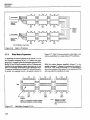
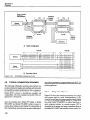
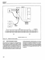
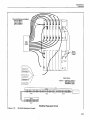
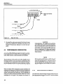
1
Model 7076General
Dual 4 x 12
Instruction
Manual
Contains Operating
Publication
Document
Date: April 1991
Number:
7076-901-01
Purpose Matrix
and Servicing
Rev. B
Information
Card
WARRANTY
Keithley Instruments, Inc. warrants this product to be free from defects in material and workmanship for a period of 1 year from date of
shipment.
Keithley Instruments, Inc. warrants the following items for 90 days from the date of shipment: probes, cables, rechargeable batteries,
diskettes, and documentation.
During the warranty period, we will, at our option, either repair or replace any product that prows to be defective
To exercise this warranty, write or call your local Keithley representative, or contact Keithley headquarters in Cleveland, Ohio. You will
be given prompt assistance and return instructions. Send the product, transportation prepaid, to the indicated service facility. Repairs
will be made and the product returned, transportation prepaid. Repaired or replaced products are warranted for the balance of the original warranty period, or at least 90 days.
LIMITATION
OF WARRANTY
This warranty does not apply to defects resulting from product modification without Keithley’s express written consent, or misuse of
any product ot’ part. This warranty also does not apply to fuses, software. non-rechargeable batteries, damage from battery leakage, or
problems arising from normal wear or failure to follow instructions.
THIS WARRANTY IS IN LIEU OF ALL OTHER WARRANTIES, EXPRESSED OR IMPLIED, INCLUDING ANY IMPLIED
WARRANTY OF MERCHANTABILITY
OR FITNESS FOR A PARTICULAR USE. THE REMEDIES PROVIDED HEREIN ARE
BUYER’S SOLE AND EXCLUSIVE REMEDIES.
NEITHER KEITHLEY INSTRUMENTS, INC. NOR ANY OF ITS EMPLOYEES SHALL BE LIABLE FOR ANY DIRECT, INDIRECT, SPECIAL, INCIDENTAL OR CONSEQUENTIAL DAMAGES ARISING OUT OF THE USE OF ITS INSTRUMENTS AND
SOFTWARE EVEN IF KEITHLEY INSTRUMENTS, INC., HAS BEEN ADVISED IN ADVANCE OF THE POSSIBILITY OF
SUCH DAMAGES. SUCH EXCLUDED DAMAGES SHALL INCLUDE, BUT ARE NOT LIMITED TO: COSTS OF REMOVAL
AND INSTALLATION, LOSSES SUSTAINED AS THE RESULT OF INJURY TO ANY PERSON, OR DAMAGE TO PROPERTY.
Keithley Instruments, Inc. * 28775 Aurora Road * Cleveland, OH 44139 - 216-248-0400 -Fax: 216-248-6168 - http://www.keithley.com
General Purpose Matrix Card Dual 4 x 12
Model 7076
Instruction Manual
01990, Keithley Instruments, Inc.
All rights reserved.
Cleveland, Ohio, U. S. A.
Document Number: 7076-901-01
All Keithley product names are trademarks or registered trademarks of Keithky Instruments, Inc.
Other brand and product names are trademarks or registered trademarks of their respective holders
SAFETY PRECAUTIONS
The following
safety precautions
should be observed before using the Model 7076 and the associated instruments.
This matrix card is intended for use by qualified personnel who recognize shock hazards and are familiar with the safety
precautions required to avoid possible injury. Read over this manual carefully before using the matrix card.
ALWAYS remove power from the entire system (Model 707, test instruments,
before doing any of the following:
1. Installing
or removing
DUT, etc.) and discharge any capacitors
the matrix card from the mainframe.
2. Connecting or disconnecting cables from the matrix card. The pins of cable connectors are easily accessible making
them extremely hazardous to handle while power is applied.
3. Making internal changes to the card (such as removing
or installing
jumpers).
Exercise extreme caution when a shock hazard is present at the test f?xture. User-supplied lethal voltages may be present
on the tlxture or the connector jacks. The American National Standards Institute (ANSI) states that a shock hazard exists
when voltage levels greater than 30V RMS or42.4V peak are present. A good safety practice is to expect that hazardous
voltage is present in any unknown circuit before measuring.
Do not connect the card or any other instrumentation
to humans.
Inspect the connecting cables and test leads for possible wear, cracks, or breaks before each use.
For maximum
under test.
safety, do not touch the test fixture, test cables or any instruments
while power is applied to the circuit
Do not touch any object which could provide a current path to the common side of the circuit under test or power line
(earth) ground.
Do not exceed the maximum
manual.
signal levels of the test fixture, as defined in the specifications
and operation section of this
Do not connect the matrix card directly to unlimited power circuits. This product is intended to be used with impedance
limited sources. NEVER connect the matrix card directly to ac mains.
When connecting sources, install protective
The chassis connections
connections.
devices to limit fault current and voltage to the card.
must only be used as shield connections
for measuring
circuits, NOT as safety earth ground
Model 7076 Dual 4x12 Two-Pole Matrix
Card
MATRIXCON”GURATION:Dual4rowsby12columns.Alsocanfigurableas8rowsby
12 mhmns. Jumpers can be removed to isolate any row from the backplane.
CROSSPOINT
CONFIGURATION:
2 pole Form A (HI, GUARD).
CONNECTOR
TYPE: 25.pin subminiature D connector, two for column connection, one
far row connection.
MAXIMUM SIGNAL LEVEL:
DC Signals: IIOV DC, IA switched, 30VA ksistive
load).
AC Signals: 175” AC peak, IA switched, 62SVA (resistive load).
COMMON
MODE VOLTAGE: IIOV DC, 175V AC peak pin to pi” or pi” to chassi%
CONTACT
LIFE:
Cold Switching: 10s closures.
At M.Mm”rn
Signal Level: 105 closures.
PATH RESISTANCE
(per conductorb <0.5On initial, <1.5R at end of contact life
CONTACTPOTENTIAL:
<5pV per crosspaint (HI lo GUARD).
OFFSET CURRENT: <lOOpA.
ISOLATION:
PatlIz >lOw2, <7PF.
Differential:
>lOQ l2opF nominal.
Common Mode: >lOQ 2OOpFnominal.
CROSSTALK
(IMHr, Mfi 1o;db <-5OdB.
INSERTION
LOSS (IMHz, 5On source, 5OR load): 0.05dB typical.
3dB BANDWIDTH
(500 load): 15MHz typical.
RELAY DRIVE CURRENT (per crosspoint): 28mA.
RELAY SE’ITLING TIME: <3ms.
ENVIRONMENT:
Operating: 0’ to 5O”C, up to 35°C at 70% R.H.
storage: -250 to WC.
ACCESSORY SUPPLIED: instruction manual, jumpers for 8 x 12 expansion.
5pcifications
subject to change without
notice.
Column
Jumpers
- (user
Table of Contents
SECTION
1.1
1.2
1.3
1.4
1.5
1.6
1.7
1.7.1
1.7.2
1.7.3
1.8
1.9
1-
INTRODUCTION
FEATURES
.
WARRANTY INFORMATION
MANUAL ADDENDA
SAFETY SYMBOLS AND TERMS
SPECIFICATIONS
. .
UNPACKING
AND INSPECTION
Inspection for Damage . . .
Shipping Contents
Instruction Manual
REPACKING FOR SHIPMENT
OPTIONAL ACCESSORIES
SECTION
2.1
2.2
2.3
2.4
2.4.1
2.4.2
2.5
2.5.1
2.5.2
2.5.3
2.5.4
2.6
2.6.1
2.6.2
2.7
2.7.1
2.7.2
2.7.3
2.7.4
2.7.5
2.8
2.8.1
2.8.2
2.8.3
2.8.4
2.9
2-
1-l
l-1
1-l
1-l
1-l
1-l
1-l
1-l
l-2
l-2
l-2
l-2
Operation
.......................................
INTRODUCTION
..............................
HANDLING
PRECAUTIONS
....................
CARD INSTALLATION
AND REMOVAL
........................
BASIC MATRIX CONFIGURATIONS
.........................................
4x24Matrix
8xl2Matrix
.........................................
TYPICAL MATRIX SWITCHING SCHEMES ..................
................................
Single-ended Switching.
Differential Switching ..................................
Guarding
...........................................
Sensing .............................................
CONNECTIONS
.......................................
Standard Cable (Model 7075-MTC) ........................
High Isolation Cables (Model 7076-RMTC and Model 707&CMTC)
MATRIXEXPANSION.
..................................
Backplane Row Jumpers ................................
Narrow Matrix Expansion ...............................
Wide Matrix Expansion .................................
...........................
Partial Matrix Implementation
............................
Mainframe Matrix Expansion
T(PICAL CONNECTION
SCHEMES ........................
....................................
Single Card System
Multiple Card System ..................................
Multiple Mainframe System .............................
Matrix/Multiplexer
System ..............................
...........................
BANDWIDTH
and CROSSTALK
SECTION 3 3.1
3.2
3.2.1
General Information
2-l
2-l
2-l
2-2
2-6
2-7
2-8
2-8
2-8
2-9
2-9
2-10
2-11
2-13
2-15
2-15
2-17
2-18
2-19
2-19
2-20
2-20
2-21
2-21
2-22
2-25
Applications
INTRODUCTION
..............................................................
.......................................
THICK FILM RESISTOR NETWORK TESTING
..............................................
Four-terminal Ohms Measurements
3-1
3-l
3-3
3.2.2
3.3
3.3.1
3.3.2
....................................................
VoltageDividerChecks
TRANSISTOR TESTING ....................................................
Current Gain Checks ......................................................
..................................................
Is and Vm Measurements
SECTION
4.1
4.2
4.3
4.4
4.4.1
4.4.2
4.4.3
4.4.4
4.4.5
4.4.6
4.4.7
4.4.8
4.5
4.5.1
4.5.2
4.5.3
4.6
4.7
4.7.1
4.7.2
5-
3-4
3-6
3-6
3-8
Service Information
................................
INTRODUCTION
........
HANDLING
AND CLEANING PRECAUTIONS
RELAY TEST PROGRAM SET-UP ...................
PERFORMANCE VERIFICATION
...................
.......................
Environmental
Conditions
.......................
Recommended Equipment
........................
Matrix Card Connections
Path Resistance Tests ...........................
Offset Current Tests ............................
Contact Potential Tests ..........................
Path Isolation Tests .............................
Differential and Common Mode Isolation Tests ........
IWNCIPLES OF OPERATION
......................
.............................
Card Identification
Switching Circuitry .............................
Power Up Safeguard ............................
SPECIAL HANDLING
OF STATIC-SENSITIVE
DEVICES
............................
TROUBLESHOOTING
.......................
Recommended Equipment
Troubleshooting
Procedure .......................
SECTION
5.1
5.2
5.3
5.4
5.5
4-
.
Replaceable
.............
.............
.............
.............
.............
.............
.............
.............
.............
.............
.............
.............
.............
.............
.
.............
.............
.............
.............
.............
.............
.
4-l
4-l
4-l
4-2
4-2
4-3
4-3
4-3
4-4
4-6
4-7
4-9
4-12
4-12
4-12
4-12
4-13
4-13
4-13
4-13
Parts
..........................................................
INTRODUCTION
PARTSLIST ..............................................................
.................................................
ORDERING INFORMATION
........................................................
FACTORYSERVICE
COMPONENT LAYOUT AND SCHEMATIC DIAGRAM ............................
5-l
5-l
5-l
5-l
5-l
List of Illustrations
SECTION
Figure
Figure
Figure
Figure
Figure
Figure
Figure
Figure
Figure
Figure
Figure
Figure
Figure
Figure
Figure
Figure
Figure
Figure
Figure
Figure
Figure
Figure
Figure
Figure
Figure
2-
Matrix Card Installation
..........................................
Model7076 ....................................................
Simplified Component Layout .....................................
Model 7076 Configured as4 x 24 Matrix ..............................
..............................
Model7076Configuredas8x12Matrix
.......................................
Column Jumper Installation
Single-ended Switching Example (Using 7075-MTC Cable) ................
Differential Switching Example (Using High Isolation Cables) ..............
Driven Guard Example (Using High Isolation Cables) ....................
Sensing Example (Using High Isolation Cables) .........................
D-sub Receptacle Contact Assignments ...............................
Model 7075-MTC Standard Cable ...................................
D-sub Plug Pin Assignments for High Isolation Cables ...................
Schematic Drawing of Backplane Jumper Configuration
(Factory Default) .....
Narrow Matrix Example (4 x 72) ....................................
.................
Dual4x72Matrices
............................
...........................
. ..........
WideMatrixExample(8x36)
Partial Matrix Expansion (8 x 36) ....................................
Single Card System Example .......................................
Multiple Card System Example .....................................
Multiple Mainframe Example ......................................
Matrix/Multiplexer
System .......................................
-3dB Bandwidth (Crosspoint Al closed, Rs = RL = 5OQ) ...................
-3db Bandwidth (Crosspoint HI2 closed, RS= RRL= 500) .................
Crosstalk (Crosspoints Gl and H2 closed, 5OQ source on ROW G, 500 load on
COLUMN l’, Measurements at ROW H) ..............................
Crosstalk (Cross oints All and 812 closed, 5On source on ROW A, 5OQ load on
COLUMN 11, Mpeasurements at ROW B) ..............................
2-l
2-2
2-3
24
2-5
2-6
2-7
2-8
2-9
2-10
2-11
2-12
2-13
2-14
2-15
2-16
2-17
2-18
2-19
2-20
2-21
2-22
2-23
2-24
2-25
Figure 2-26
SECTION
Figure
Figure
Figure
Figure
Figure
Figure
Figure
Figure
3-l
3-2
3-3
34
35
3-6
3-7
3-8
Operation
3-
.
2-3
24
2-5
2-6
2-7
2-8
2-8
2-8
2-9
2-9
2-10
2-12
2-14
2-16
2-17
2-18
2-18
2-20
2-21
2-22
2-23
2-24
2-25
2-25
2-26
2-26
Applications
Thick Film Resistor Network Testing
4-Terminal Ohms Measurements
Voltage Divider Checks
.
.
Transistor Testing .
.
.
Transistor Current Gain Checks
.
Common Emitter Characteristics of an NPN Silicon Transistor
.
Transistor IE Measurements
Transistor VsEMeasurements
.........
.........
.........
.........
.........
.........
.........
.........
3-2
3-3
3-5
3-6
3-7
3-8
3-9
3-10
SECTION 4 Figure
Figure
Figure
Figure
Figure
Figure
Figure
Figure
Figure
Figure
4-l
4-2
4-3
4-4
4-5
4-6
4-7
4-8
4-9
4-10
Service Information
Relay Test Setup .
.
.......
Path Resistance Testing . . . .
.. ...
Common Mode Offset Current Testing
Differential Mode Offset Current Testing
Contact Potential Testing
.
Path Isolation Testing (Guarded)
Differential Isolation Testing
..
.
Common Mode Isolation Testing
.
.
.
ID Data Timing Diagram
D-sub Receptacle Contact Assignments .
.................
.................
.................
.................
.................
.................
.................
.................
.................
.................
4-2
44
4-5
4-6
4-7
4-8
4-11
4-11
4-12
4-14
List of Tables
SECTION 2 Table
Table
Table
Table
Table
Table
Table
Table
2-1
2-2
2-3
24
2-5
2-6
2-7
2-8
SECTION 4 Table
Table
Table
Table
Table
4-l
4-2
4-3
44
4-5
Operation
Column Number Assignments
4 x 24 Matrix Crosspoint Assignments
. .. .
Available Cables and Connectors
Cable Conductor Identification
(Model 7075-MTC)
Model 7076.RMTC Conductor Identification
Model 7076~CMTC Conductor Identification
.
Narrow Matrix Expansion* .
.
.
Wide Matrix Expansion’
.
..............
..............
..............
..............
..............
..............
..............
..............
2-3
2-7
2-11
2-13
2-15
2-15
2-17
2-19
Service Information
Verification Equipment ................................
Path Isolation Tests ...................................
Differential and Common Mode Isolation Test ..............
................
Recommended Troubleshooting
Equipment
............................
Troubleshooting
Summary”
....................
....................
....................
....................
....................
4-3
4-9
4-10
4-13
4-14
SECTION 1
General Information
1 .l
INTRODUCTION
This section contains general information
about the
Model 7076 General Purpose Matrix Card Dual 4 x 12.
1.2
1.5
SAFETY SYMBOLS
AND TERMS
The following symbols and terms may be found on an instrument or used in this manual.
Then
symbol on an instrument indicates that the user
should refer to the operating instructions located in the
instruction manual.
FEATURES
The Model 7076 is a general purpose, two-pole, dual 4 x
12 (four row by 12 column) matrix card. Some of the key
feahxes include:
Guard capability. Each HI path on the PC board is surrounded by a second path that can be used for guarding.
l
Low contact potential and offset current for minimal
effects on low-level signals.
. Quick disconnects using 2.5pin D-Sub connectors on
the rear panel.
. Row backplane jumpers. Cutting jumpers disconnects
rows from the Model 707 backplane.
l
Column jumpers. Installing jumpers configures card
as an 8 x 12 matrix.
l
1.3
WARRANTY
MANUAL
The WARNING
heading used in this manual explains
dangers that might result in personal injury or death. Always read the associated information very carefully before performing the indicated procedure.
The CAUTION
heading used in this manual explains
hazards that could damage the matrixcard. Such damage
may invalidate the warranty.
INFORMATION
Warranty information is located on the inside front cover
of this instruction manual. Should your Model 7076 require warranty service, contact the Keithley representative or authorized repair facility in your area for further
information. When returning the matrix card for repair,
be sure to fill out and include the service form at the back
of this manual in order to provide the repair facility with
the necessary information.
1.4
The f symbol on an instrument shows that high voltage
may be present on the terminal(s). Use standard safety
precautions to avoid personal contact with these voltages.
ADDENDA
Any improvements
or changes concerning the matrix
card or manual will be explained in an addendum included with the unit. Be sure to note these changes and
incorporate them into the manual.
The terms COLUMN, COLUMNS, ROW and ROWS are
used in this manual as a reference to the rear panel receptacles of the matrix card.
1.6
SPECIFICATIONS
Model 7076 specifications may be found at the front of
this manual. These specifications are exclusive of the matrix mainframe specifications.
1.7
1.7.1
UNPACKING
Inspection
AND INSPECTION
for Damage
The Model 7076 is packaged in a re-sealable, anti-static
bag to protect it from damage due to static discharge and
l-l
SECTION 1
General Information
from contamination that could degrade its performance.
Before removing the card from the bag, observe the following precautions on handling.
Handling
Precautions:
1. Always grasp the card by the handle and side edges.
Do not touch the edge connectors and do not touch
board surfaces or components.
2. When not installed in a Model 707 mainframe, keep
the card in the anti-static bag and store in the original packing carton.
1.8
If you are going to install the card in the Model 707 mainframe at this time, be sure to follow the additional handling precautions explained in paragraph 2.2.
1.7.2
Shipping
The following
order:
l
l
l
l
Contents
items are included
with every Model 7076
Model 7076 Dual 4 x 12 Two-pole Matrix Card.
Column jumper sets.
Model 7076 Instruction Manual.
Additionalaccessoriesasordered.Note
that thecables
may be shipped in a separate packing carton.
1.7.3
Instruction
Manual
The Model 7076 Instruction Manual is three-hole drilled
so that it can be added to the three-ring binder of the
Model 707 Switching Matrix Instruction Manual. After
removing the plastic wrapping, place the manual in the
binderafterthemainframeinstructionmanual.Notethat
a manual identification
tab is included and should precede the matrix card instruction manual.
If an additional instruction manual is required, order the
manual package, Keithley part number 7076-901-00. The
manual package includes an instruction manual and any
applicable addenda.
l-2
FOR SHIPMENT
Should it become necessary to return the Model 7076 for
repair, carefully pack the unit in its original packing carton or the equivalent, and include the following information:
l
l
l
Advise as to the warranty status of the matrix card.
Write ATTENTION
REPAIR DEPARTMENT
on the
shipping label.
Filloutandincludetheserviceformlocatedat
theback
of this manual.
1.9
Afterremovingthecard
fromitsanti-staticbag,inspectit
for any obvious signs of physical damage. Report any
such damage to the shipping agent immediately.
REPACKING
OPTIONAL
The following
Model 7076:
ACCESSORIES
accessories are available
Model 7075-MTC
Assembly
Standard RowlCohmn
for use with the
Cable
The Model 707S-MTC is a three-meter (IO-feet), 24 conductor cable terminated with a 25-pin D-subminiature
(D-sub) connector on both ends. This cable connects to
either the ROWS or COLUMN receptacles on the rear
panel of the card. This cable assembly is constructed using a general purpose flat cable that is fitted into a
shielded round jacket.
Thiscable iscommonly cut at a convenient length to provide two separate cables. The cables can then be used to
connect to both the ROW and COLUMN receptacles. The
unterminated ends of the cables can then be connected to
instrumentation
and DUTs.
Model 7076-RMTC
HighIsolationRow
CableAssembly
The Model 707GRMTC is a three meter (IO-feet), 2%conductor cable terminated with a 25pin D-sub connectors
onbothendsandisconfigured
tomatetotheROWreceptacle of the Model 7076. Each conductor pair (signal and
drain) of the shielded cable is wrapped with insulated
foil to minimize crosstalk between conductor pairs.
This cable is commonly cut at a convenient length to provide two separate cables. The cables can then be used to
connect to both COLUMN
receptacles. The unterminated ends of the cables can then be connected to instrumentation and DUTs.
SECTION 1
General
Model 7076-Ch4TC High isolation
Assembly
Column Cable
The Model 7076-CMTC is a 3-meter (lo-feet), 28-conductor cable terminated with a 25-pin D-sub connector on
both ends. This cable connects to either one of the two
COLUMN receptacles on the Model 7076. Each conductor pair (signal and drain) of the shielded cable is
wrapped with insulated
tween conductor pairs.
foil to minimize
Information
crosstalk be-
This cable is commonly cut at a convenient length to provide two separate cables. The cables can then be used to
connect to both COLUMN
receptacles. The unterminated ends of the cables can then be connected to instrumentation and DUTs.
1-3
SECTION 2
Operation
2.1
INTRODUCTION
WARNING
The matrix configuration
procedures in this
section should only be performed by qualified personnel who recognize shock hazards
and are familiar with the safety precautions
required to avoid possible injury. Review
the safety precautions found at the front of
this manual.
This section contains information on aspects of matrix
card operation and is arranged as follows:
2.2
To avoid possible contamination, always grasp the card
by the handle and side edges. Do not touch the edge connectors of the card and do not touch board surfaces or
components. On D-subminiature (D-sub) connectors, do
not touch areas adjacent to the electrical contacts.
CAUTION
Do not store the card by leaning it against an
object (such as B wall) with its edge connectars in contact with a contaminated surface
(such as the flood. The edge connectors will
become contaminated, and tapes and solder
connections on the PC board may break as
the card bends. ALWAYS store the card (in
its anti-static bag) in the original shipping
carton.
lMiOIl.
2.3 Card Installation and Removal: Covers the basic procedure for installing and removing the card from the
Model 707 Switching Matrix.
2.5 Typical Matrix Switching Schemes: Explains some
of the basic ways that a matrix can be used to source or
measure. Covers single-ended switching, differential
(floating) switching, sensing, shielding, and guarding.
2.6 Connections:
JXxwses the various methods and
techniques that can be used to connect DUTs and in&umentation to the matrix card.
PRECAUTIONS
To maintain high impedance isolation, care should be
taken when handling the matrix card to avoid contamination from such foreign materials as body oils. Such
contamination
can substantially
lower leakage resistances, degrading performance.
2.2 Handling
Precautions:
Details precautions
that
should be observed when handling the matrix card to ensure that its performance is not degraded due to contami-
2.4 Basic Matrix Configurations:
Covers the basic matrix
configurations that the card can be configured for; dual 4
x 12 matrices, a single 4 x 24 matrix or a single 8 x 12 matrix.
HANDLING
Dirt build-up over a period of time is another possible
source of contamination. To avoid this problem, operate
the mainframe and matrix card in a clean environment.
If the card becomes contaminated, it should be tboroughly cleaned as explained in paragraph 4.2.
2.3
CARD INSTALLATION
AND REMOVAL
2.7 Matrix Expansion: Discusses the various matrix configurations that are possible by using multiple cards. The
significance of backplane row jumpers on matrix configurations is also covered here.
WARNING
To avoid electrical shock that could result in
injury or death, ALWAYS remove power
from the entire system (Model 707, test instruments, DUT, etc.) and discharge any capacitors before doing any of the following:
2.8 Typical Connection Schemes: Provides examples of
external connections for single card, multiple card and
multiple mainframe systems.
1. Installing
or removing
from the mainframe.
the matrix
card
2-1
SECTION 2
operation
2. Connecting or disconnecting
cables from
the matrix card. The pins of the cable connectors are easily accessible making them extremely hazardous to handle while power is
applied.
3. Making internal changes to the card (such
as removing or installing jumpers).
Cable connections to the matrix card make it difficult to
install or remove the card from the mainframe. Thus, it is
advisable to install the card and then make cable connections to it. Conversely, cables should be disconnected before removing the card from the mainframe.
Referring to Figure 2-1, perform the following procedure
to install the Model 7076 matrix card in the Model 707:
CAUTION
Contamination
will degrade the performance of the matrix card. To avoid contamination, always grasp the card by the handle and
side edges. Do not touch the edge connectors
of the card, and do not touch the board SUP
faces or components. On connectors, do not
touch areas adjacent to the electrical contacts.
Turn the Model 707 off.
Select a slot in the mainframe and remove the coverplate. The cover-plate is fastened to the mainframe
chassis with two screws. Retain the cover-plate and
screws for future use.
With the relay side of the matrix card facing towards
the fan, feed the card into the slot such that the top
and bottom card edges seat into the card edge guides
of the mainframe. Slide the matrix card all the way
into the mainframe and tighten the two spring
loaded panel fasteners.
WARNING
The mounting screws must be secured to ensure a proper chassis ground connection between the card and the mainframe. Failure to
properly secure this ground connection may
result in personal injury or death due to electric shock.
2-2
4. To remove the card from the mainframe make sure
the Model 707 is off, power is removed from external
circuitry, and then reverse the above procedure.
2.4
BASIC MATRIX CONFIGURATIONS
A simplified schematic of the Model 7076 matrix card is
shown in Figure 2-2A. As shipped from the factory, the
matrix card is configured as two separate 4 x 12 matrices.
Each of the 96 crosspoints is made up of a two-pole
switch. By closing the appropriate crosspoint switch, any
matrix row can be connected to any column in the same
matrix. In this manual, the columns of every Model 7076
matrixcard arereferred to as columns 1 through 12 and 1’
through 12’. Columns 1 through 12 correspond to the columns receptacle (on the connection panel) labeled “TO
ROWS A-D”, while references to columns 1’ through 12
correspond to the columns receptacle labeled “TO ROWS
E-H”.
Note that even though there are 24 unique columns in
this configuration, the Model 707 recognizes only 12 columns for programming purposes. The crosspoint assignments for the matrix card are provided in Figure Z-28.
For example, to connect r6w A to column 10, the Model
707 would have to be programmed to close crosspoint
A10 (row A, column 10); and to connect row E to column
10’ (22nd column), crosspoint El0 would have to be
closed. These crosspoint closures assume that the matrix
card is installed in slot 1 of the mainframe. The crosspoint
assignments in Figure 2-2B are valid regardless of how
the card is configured.
The column number assignments for programming the
Model 707 are determined by the mainframe slot that the
matrixcard is installed in. For example, the column number assignments of a matrix card installed in slot 4 of the
mainframe are numbered 37 through 48. Column number assignments for all six mainframe slots are listed in
Table 2-1.
Notice in Figure 2-2A that there are backplane jumpers
located on the matrix card. With the jumpers installed,
the matrix card is connected to the backplane of the
Model 707 allowing matrix expansion (see paragraph
2.7). With the jumpers removed, the matrix card is isolated from any other cards installed in the mainframe.
The physical location of these jumpers on the board is
shown in Figure 2-3.
SECTION 2
Operation
Mounting Screws
Card Handle
Figure 2-1.
Matrix Card Installation
Table
2-l.
Column
1 7076 Card Location
Slot
Slot
Slot
Slot
Slot
Slot
1
2
3
4
5
6
1
Number
Matrix
Assignments
Column
1 through
13 through
25 through
37 through
49 through
61 through
Numbers
12
24
36
48
60
72
2-3
SECTION 2
r-----
_------------
---
1
A. Simplified Schematic
r----
‘igure 2-2.
2-4
Model 7076
--------------
1
SECTION 2
Oaeration
I
1
I
0
I
I
I
l
0
.
Cigure 2-3.
SimpIified Component layout
2.4.1
4 x 24 Matrix
Removing the backplane jumpers will isolate the 4 x 24
matrix from any other card installed in the mainframe.
Figure 2-4 shows how the Model 7076 can be configured
as a single 4 x 24 matrix. Row jumper wires are used to
connect rows A, B, C and D to rows E, F, G and H respectively. These connections can be made wherever it is
most convenient, such as at the connector of a customized cable ass$mbly, or at the instrumentation
(see
Figure Z-15) or DUT test fixture.
In a multiple
left installed,
Crosspoint assignments for progmmming the Model 707
do not change even though the matrix configuration of
the card has changed (see Figure 2-28). For example, to
connectrowAtothe24th(12’)columnofthe4x24matrix
(see the equivalent circuit in Figure 2-4), the Model 707
would have to be programmed to close crosspoint El2
kmmingtbecardisinstaUedinslot
1 of themainframe).
Table 2-2 provides the crosspoint assignments for a
Mode17076 configuredasa4x24matrixinstalled
inslot 1
of the mainframe. Table2-I provides the column number
assignments for the other mainframe slots.
card system where badcplane jumpers are
row jumpers are only required at one card.
r--------------------~
Fmv
J”rnpers
\
Column
II
I
I
I
1
2
3
4
5
6
TTTTTTTTI
7
8
I II/~
Backplane
Jumpers
I
I
II
I
I
I
I
Column
I
Equivalent Circuit
‘igure 2-4.
2-6
Model 7076 Configuredas 4 x 24Matri.r
SECTION 2
Operation
Table 2-2.
M.&X
Row*
1
A(E)
B(F)
C(G)
D(H)
Al
Bl
Cl
Dl
Crosspoint
Assignments
Matrix Column
r----
2.4.2
4 x 24 Matrix
2
3
A2
B2
A3
c2
E
D3
D2
. ..
:::
12
1’
2’
3’
A12
B12
El
Fl
E2
F2
E3
Cl2
Gl
D12
Hl
----------------_
Column
8 x 12 Matrix
Figure 2-5 shows that the Model 7076 can be configured
asastandard8~12matibyinstallingtbecolumnjumpem. The location of the column jumpers on the PC-board
is shown in Figure 2-3. As shipped from the factory, the
12columnjumperssetsarenotinstalled.
Installingthe
E
. ..
12’
El2
F12
:::
E
H3
G12
H12
1
jumpers sets, as shown in Figure 2-6, configures
Model 7076 as an 8 x 12 matrix.
the
With the Model 7076 backplane jumpers installed, the 8 x
12 matrix is connected to the backplane of the Model 707
allowing matrix expansion (see paragraph 2.7). With the
backplane jumpers removed, the 8 x 12 matrix will be isolated from any other card installed in the mainframe.
2-7
SECTION 2
Operation
2.5.1
COI 1
Single-ended
Switching
Cal 1
Jumpers
H
.
.
In the single-ended switching configuration, the source
or measure instrument is connected to the DUT through
a single pathway as shown in Figure 2-7. Note that the
shield of the Model 7075~MTC cable is connected to the
shield around the DUT.
.
.
Not Installed
(as shipped)
Note : See Fig. 2-3 for location
of jumpers on Pcboard.
?gure 2-6.
2.5
2.5.2
Column Jumper Installation
Differential
Switching
The differential
or floating switching configuration
is
shown in Figure 2-8. The advantage of using this configuration is that the terminals of the source or measure
inslmment
are not confined to the same matrix
crosspoint. Each terminal of the instrument can be connected to any matrix crosspoint. The guard terminals of
the matrix card are used as a shield.
TYPICAL MATRIX SWITCHING
SCHEMES
The following paragraphs describe some basic switching
schemes that are possible with a two-pole switching matrix.
1
Shield
Source or
Measure
Figure 2-7.
L---l
7076
Single-ended Switching Example (Using 707.5MTC Cable)
A
‘igure 2-8.
2-8
Diflerential
Switching Example (Using High Isolation Cables)
Earth Ground
SECTION 2
0pL?Mi0?l
2.5.3
Guarding
2.5.4
Figure 2-9 shows how the matrix card can be used with a
driven guard. Since the driven guard is at virtually the
.same potential as signal high, protection from possible
hazardous voltages (up to 175V peak) must be provided.
Many instruments have the capability of configuring
their input or output such that a driven guard is placed
on the inner shield of a triax connector. The outer shield,
connected to system common, provides protection from
the guard voltage. When making connections from the
matrix card to the DUT, a safety shield may be required,
depending on the type of connectors used.
Sensing
Figure Z-100 shows how the matrix card can be configured to use instruments that have sensing capability. The
main advantage of using sensing is to cancel the effects of
matrix card path resistance (4.5) and the resistance of
external cabling. Whenever path resistance is a consideration, sensing should be used.
The standard cable (Model 7075-I&K) can also be used,
however the high (H) paths in the cable will not be SWrounded by guard (G).
4
h
7076
Driven Guard Example (Using High Isolation Cables)
Source or
MWSWS
7076
Figure Z-10.
Sensing Example (Using High Isolation Cables)
System Common
Earth Ground
SECTION 2
Operation
2.6
Pin identification for the D-sub receptacles is provided in
Figure 2-11. Adjacent to the each contact designation of
the D-sub receptacles is the corresponding row or column that it is internally connected to.
CONNECTIONS
CAUTION
To prevent damage (not covered by the warranty) and a possible safety hazard, do not
exceed the maximum allowable limits of the
Model 7076. Maximum signal levels are
located at the
listed in the specifications
Cable Connections
front of the manual.
As shipped, all rows and columns of the Model 7076 matrix card are connected to the three 25-pin D-sub receptacles mounted on the rear panel of the matrix card. One receptacle is provided for row connections and two receptacles are provided for column connections. The COLUMNS receptacle located near the top is for rows A
through D, while the other COLUMNS receptacle is for
rows E through H.
There are two basic cable types available to make connections to the matrix card; the standard cable (Model
7075~MTC),
and high
isolation
cables (Model
7076~RMTC and Model 7076-CMK).
Basically, the standard cable is a general purpose cable that will mate to
either the ROWS or COLUMN receptacles. The high isolation cables provide better isolation between paths. The
Model 7076-RMTC is used to connect to the ROWS receptacle, while the Model 707~CMTC is used to connect to
the COLUMN receptacles.
The available cables, as well as some miscellaneous connectors for customized user supplied terminations, are
N/C
N/C
Row A Gd
Cd 1 Gd
Cd 1 HI
Row A HI
Row A Gd
Cd 2 Gd
Col2HI
Row B Gd
Row B HI
Cd 3 Gd
Cd 3 HI
Cd 4 Gd
Columns
(A W
Row 6 Gd
Row C Gd
Co14 HI
Row C HI
Row C Gd
Cd 5 Gd
Co15 HI
ROW D Gd
Row D HI
Cd 6 Gd
Co16 HI
Row D Gd
Row E Gd
Cd 7 Gd
Co17 HI
Row E HI
Row E Gd
Cd 6 Gd
Co16 HI
Row F Gd
Row F HI
Cd 9 Gd
Co19 HI
CollOGd
Col 10 HI
Columns
(E H)
Row F Gd
Row G Gd
Row G HI
Row G Gd
Co111 Gd
Col 11 HI
Co112 Gd
View of receptacles
looking at Rear Panel
Row H Gd
Row H HI
Cd 12 HI
A) COLUMNS Receptacle
(1 of 2)
‘igure Z-11.
2-10
D-sub Receptacle Contact Assigments
Row H Gd
HI = High
Gd = Guard
N/C = No connection
B) ROWS Receptacle
SECTION 2
Ckmntion
Table
2-3.
Available
Manufacturer
Model
or Part Number
Keithley
Model 7075.MTC Standard Cable
Keithley
Model 7076.CMTC High Isolation
Columns Cable
Keithley
Model 7076-RMTC High Isolation
Rows Cable
Keithley
cs400
Keithley
C%Ol
Keithley
Belden
G-590
9868
82257000
3357-9225
Cables
and Connectors
Description
Standard three-meter (10 feet) cable assembly terminated
with 25-pin D-sub plugs on both ends. Mates to either the
ROWS or COLUMN receptacles of the matrix card.
Three-meter (10 feet), high isolation (for high isolation) cable
assembly terminated with 25-pin D-sub plugs on both ends.
Use to mate to either COLUMNS receptacle of the matrix
card.
Three-meter (10 feet), high isolation (for high isolation) cable
assembly terminated with 25-pin D-sub plugs on both ends.
Use to mate to the ROWS receptacle of the matrix card.
25-pin D-sub plug that will mate to the ROWS and COLUMN receptacles of the matrix card. Solder-cup connections
simplify the building of custom cables.
25-contact D-sub receptacle that will mate to cables terminated with a 25-pin D-sub plug.
Plastic backshell housing for CS400.
High isolation cable. Same cable used for the Models
7076-RMTC and 707tXMTC cable assemblies. See paragraph 2.6.2 for description.
25-pin D-sub plug for customized ribbon cable assemblies.
Junction shell for 3M 8225-7000 D-sub plug.
summarized in Table 2-3. The cables available from
Keithley are described in more detail in paragraphs 2.6.1
and 2.6.2.
The same basic procedure applies for connecting
ble plug to a test fixture receptacle.
2.6.1
WARNING
To avoid electrical shock that could result in
injury or death, ALWAYS remove power
from the entire system (Model 707, test instruments, DUT, etc.) and discharge any capacitors before connecting or disconnecting
cables from the matrix card. The pins of the
cable connectors are easily accessible making them extremely hazardous to handle
while power is applied.
Use the following procedure to connect a cable terminated with a 25-pin D-sub plug to the matrix card:
1. Install thematrixcardin
theModel707mainframeas
explained in paragraph 2.3.
2. Push the plug of the cable onto the appropriate receptacle of the matrix card. The cable plug and matrix card receptacle will only mate one way.
3. Tighten the screws of the plug housing to secure it to
the panel.
Standard
the ca-
Cable (Model 7075-MTC)
The standard cable (Model 7075-MT0 is a three-meter
(10 feet), general purpose 24-conductor, shielded cable
that is terminated with a Z-pin D-sub male plug on each
end thatwillconnect
toeither theROWSorCOLLJMNreceptacles on the matrix card.
The standard cable (shown in Figure 2-12) is comprised
of a flat ribbon cable that is located inside a shielded,
round cable casing. The braided shield of the cable surrounds the ribbon cable and is subsequently connected to
chassis ground when the cable is connected to a Model
7076 that is installed in a Model 707 mainframe.
Pin designations on the D-sub plugs of the standard cable
correspond to the contact designations on the D-sub receptacles of the matrix card. Thus, if connecting the standard cable to a COLUMNS
receptacle, refer to
Figure 2-1lA for column identification.
If connecting the
standard cable to the ROWS receptacle, refer to
Figure 2-1lB for row identification.
2-11
SECTION 2
2CConductor Flat Ribbon
Cable (located inside shielded
round cable casing)
.
11
.
.z4IX
.
IO
.
9
a
7
6
5
4
3
2
21
20
19
18
17
16
15
14
13
12
11
10
9
8
7
6
5
4
3
2
1 (Red Tracer) -
23
22
.
.
21
.
20
.
.
.
19
.
.
18
.
17
.
.
.
16
.
.
15
.
.
1
.
14
.
I
I_‘------------L
4I
D-Sub
Plug
I ‘igure 2-12.
Model 7075MTC
the Standard Cable
A common way to use the standard cable is to cut it at a
convenient length. The result is two cables that are untertiated
at one end. The flat ribbon cables at the unterminated ends of the cables can then be connected to in-
2-12
.
' '.
10
9
a
7
6
5
4
3
2
.
24
23
.
.22
.
.
.
.
.
.
21
20
Note : View from
mating end of plug
19
.
.
.
.
.
1
l
-
D-Sub plug
4
L
Braided shield surrounds
ribbon cable.
Standard Cable
To connect the mati
to instrumentation and DUT, a test
fixture using a D-sub receptacle can beused to mate to the
D-sub plug of the cable. The Keithley part number for the
D-sub receptacle is listed in Table 2-3.
Modifying
::*
25
strumentation and DUT, while the other ends will mate
to the ROWS and COLUMN receptacles of the matrix
card. The conductor designations of the ribbon cable are
shown in Figure Z-12. The red tracer identifies conductor
#I of the ribbon cable. Table 2-4 is provided to correspend the ribbon cable conductors to the matrix card row
or column terminal. For example, if the standard cable is
connected to the ROWS receptacle, ribbon cable conductor #24 will correspond to Row A Guard of the matrix
card. Jf the cable was instead connected to the COLUMNS receptacle, ribbon cable conductor #24 will corre
spend to Column 1 Guard of the matrix card.
SECTION 2
Operation
Table
2-4.
Ribbon
Cable
Zonductor
I*
2
3
4
5
6
i
9
10
11
12
13
14
15
16
17
18
19
20
li
Ei
*Conductor
2.6.2
Cable Conductor
Identification
(Model 7075-MTC)
Matrix Row/Column
Terminal
Connected to
Connected to
ROWS
COLUMNS
Receptacle
Receptacle
ROW H, Guard
ROW H, HI
ROW H, Guard
ROW G, Guard
ROW G, HI
ROW G, Guard
ROW F, Guard
ROW F, IU
ROW F. Guard
ROWE; Guard
ROWE, HI
ROW E, Guard
ROW D, Guard
ROW D, HI
ROW D, Guard
ROW C, Guard
ROW C, HI
ROW C, Guard
ROW 0, Guard
ROW B, Hl
ROW 0, Guard
ROW A, Guard
ROW A, HI
ROW A, Guard
COLUMN
COLUMN
COLUMN
COLUMN
COLUMN
COLUMN
COLUMN
COLLJMN
COLUMN
COLUMN
COLUMN
COLUMN
COLUMN
COLUMN
COLUMN
COLUMN
COLUMN
COLUMN
COLUMN
COLUMN
COLUMN
COLUMN
COLUMN
COLUMN
#I of the ribbon cable is identified
12, HI
12, Guard
11, HI
11, Guard
10, HI
10, Guard
9, HI
9, Guard
8. HI
8; Guard
7, HI
7, Guard
6, HI
6, Guard
5, HI
5, Guard
4, HI
4, Guard
3, HI
3, Guard
2, HI
2, Guard
1, HI
1, Guard
by the red tracer.
High Isolation Cables
(Model 7076~RMTC and
Model 7076~CMTC)
Shielded high isolation cables (Model 707~RMTC and
Model 707~CMTC) are available to optimize performance by minimizing crosstalk between signal paths. Each
HI signal path in the cable is completely surrounded by
Guard (insulated foil) to maximize the effects of guarding. The outer foil shield of the cable is connected to the
housings of the D-sub plugs. This shield is connected to
chassis ground when the cable is connected to a Model
7076 that is properly installed in the Model 707 mainframe.
The Model 707~RMTC is a 3meter (10 feet) 28-conductar cable terminated with a D-sub plug on each end. The
plug pin assignment for this cable is configured to mate
with the ROWS receptacle of the matrix card. Pin identification for this cable is shown in Figure 2-13A.
The Model 7076~CMTC is a 3-meter (10 feet) 2&conductor cable terminated with a D-Sub plug on each end. The
plug pin assignment for this cable is configured to mate
with either of the two COLUMN receptacles of the matrix
card. Pin identification
for this cable is shown in
Figure 2-138.
For connections to instrumentation
and DUT, a test fixture using a D-sub receptacles can be used to mate to the
D-sub plugs of the cables. The Keitbley part number for
the D-sub receptacle is listed in Table 2-3.
Modifying
the High Isolation
Cable
Another way to use the Model 7076-RMTC or Model
7076CMTC is to cut the cable at asuitable length and add
appropriate user teqnination.
Each cable can then be
mated to the matrix card while the unterminated ends
can be wired to another connector or directly to instmmentation and DUT.
Each cable contains 12 conductor pairs each of which corresponds to a row or column. Each pair contains a colorcoded insulated wire (HI), and a bare drain wire (Guard).
Each pair is wrapped in an insulated, color-coded foil
which is also connected to Guard. The color combination
of the HI conductor insulator and the surrounding foil is
used for identification.
Table 2-5 identifies the conductors of the Model 7076XMTC cable, while Table 2-6 provides identjfication
for the Model 7076~CMTC cable.
Note that for both cables, the black with red foil and
white with blue foil pairs (as well as the main outer
shield) are connected to chassis ground at the housing of
the D-Sub plugs.
CAUTION
When terminating a cable that has been cut,
make sure that all exposed conductors are
properly insulated using Teflon@ or PVC
tubing and/or heat shrink material. The conductive side of the foil and drain wire of each
wire pair must be electrically isolated from
the other wire pairs.
2-13
SECTION 2
Operation
.
RowAHI
12
25
l
l
.
RowBGd
“0
10
.
RowCHI
RowDGd
‘.
8
7
Row EHI
6
5
RowFGd
4
RowGHI
Cd 1 HI
23
Cd2
.
.
22
.
.
3.
l
25
Cd 1 Gd
24
Col2Gd
l
11
.
Co13 HI
“0
l
c
.
Row C Gd
Col4HI
‘.
Col5HI
*.
.
l
’ 2o
RowDHI
”
RowEGd
l
HI
12
Row B HI
21
.
.
Row A Gd
24
l
.
HI = High
Gd = Guard
Col6HI
16
7
.
l
;I;;:;
2’
Cd 5 Gd
2o
Cal 6Gd
Note : View from
mating end of plug
l
17
’
Row F HI
. l6
RowGGd
15
Note : Unlabled pins are not connected to cable
A) ROWS Cable Plugs
(Model 7076-RMTC)
‘ipre
2-14
Z-23.
D-sub Plug Pin Assignments for High Isolation Cables
B) COLUMNS Cable Plugs
(Model 7076-CMTC)
SECTION 2
Operation
Table 2-5.
Matrix
ROW
Model 7076~RMTC Conductor
Identification
Cable Wire Color Combination
Row A
Row B
Row C
Row D
Row E
Row F
Row G
Row H
Chassis
Brown (HI), Red Foil w/Drain (Guard)
Red (HI), Red Foil w/Drain (Guard)
Orange (HI), Red Foil w/Drain (Guard)
Yellow (HI), Red Foil w/Drain (Guard)
Blue (HI), Red Foil w/Drain (Guard)
White (HI), Red Foil w/Drain (Guard)
Brown (HI), Blue Foil w/Drain (Guard)
Red (HI), Blue Foil w/Drain (Guard)
Black (Chassis). Red Foil w/Drain
(Chassis)
~’
White (Chassis), Blue Foil w/Drain
(Chassis)
Main outer shield w/Drain (Chassis)
Chassis
Chassis
Table 2-6.
Matrix
Column
Model 7076-CMTC
Identification
Conductor
Cable Wire Color Combination
Brown (Hi), Red Foil w/Drain (Guard)
Red (HI), Red Foil w/Drain (Guard)
Orange (HI), Red Foil w/Drain (Guard)
Yellow (HI,) Red Foil w/Drain (Guard)
Blue (HI), Red Foil w/Drain (Guard)
White (HI), Red Foil w/Drain (Guard)
Brown @II), Blue Foil w/Drain (Guard)
Red (HI), Blue Foil w/Drain (Guard)
Orange (HI), Blue Foil w/Drain
(Guard)
Column 10 Ydlow (HI), Blue Foil w/Drain (Guard)
Column 11 Blue (HI), Blue Foil w/Drain (Guard)
Column 12 Black (HI), Blue Foil w/Drain (Guard)
Black (Chassis), Red Foil w/Drain
Chassis
(Chassis)
Chassis
White (Chassis), Blue Foil w/Drain
(Chassis)
Chassis
Main outer shield w/Drain (Chassis)
Column
column
Column
Column
Column
column
column
Column
Column
2.7
1
2
3
4
5
6
7
8
9
MATRIX EXPANSION
With the use of additional matrix cards, larger matrices
can be configured through the backplane of the Model
707. Thus, unless otherwise noted, the examples provided in the following paragraphs assume that the Model
7076 backplane jumpers are installed.
2.7.1
Backplane
Row Jumpers
The easiest way to to accomplish matirow
expansion is
through the backplane of the Model 707 mainframe. It is
through this mainframe backplane where row connections to other cards are made. As previously explained in
paragraph 2.4, the Mode17076 has eight sets of backplane
jumpers that connect the rows of the matrix card to the
mainframe backplane.
There is another set of backplane jumpers that must be
considered when building larger matrices through rows.
This set of backplane jumpers is located in the Model 707
mainframe. With these mainframe backplane jumpers installed, the rows of all mainframe slots are connected together. With these jumpers removed, the rows of mainframe slots 1,2 and 3 are isolated from the rows of mainframe slots 4,5 and 6.
NOTE
The Model 707 is shipped with its backplane
row jumpers installed. Some configurations
require that these backplane row jumpers be
removed. The procedure to remove these
jumpers can begfound in the Model 707 Instruction Manual.
Backplane Compatibility
Considerations
The Model 7076 may be incompatible with other card
types when expansion is done through the backplane.
For example, in a particular test system it may be necessary to connect Guard of the Model 7076 (which is a twopole card) to Low of a three-pole card. As shipped, the
Model 7076 backplane row jumpers connect the Guard
signal paths to the Guard terminals of the three-pole general purpose backplane of the Model 707 mainframe. The
Low signal paths of the other card are connected to the
Low backplane terminals of the Model 707. With this configuration, Guard of the Model 7076 cannot be routed to
Low of the other card.
The Model 7076 provides some flexibility in altering the
backplane route of the guard signal paths. The backplane
row jumpers are shown in Figure 2-3 and Figure 2-14.
They have circuit designations W125 through W140. The
odd circuit designations (W125, W127, W129, W131,
W133, W135, W137 and W139) identify the guard jumpers of the card. These jumpers connect the Guard signal
paths of the card to the guard backplane terminals of the
Model 707. Adjacent to each HI jumper (identified by the
even circuit designations) are holes in the PC-board to ac-
2-15
SECTTON 2
Oaeration
commodate a jumper. By moving the guard jumpers to
these locations, the matrix card guard paths will connect
to tbe low backplane terminals of the Model 707.
ice personnel who are familiar with standard
safety precautions.
WARNING
Internal modifications to the matrix card
should only be performed by qualified stxv-
CAUTION
Solder operations require that the pc-board
be cleaned as explained in paragraph 4.2.
G
ROW0
H
Model 7076
ROWE ;
figure 2-14.
2-16
0H
L To three-pole
general pllrpose
backplane of
; Model 707
Schematic Drawing of BackplaneJumper Configuration (Factory Default)
SECTION 2
Operation
2.7.2
Narrow
Matrix
Table 2-7.
Expansion
An example of a narrow matrix is shown in Figure 2-15.
This 4 x 72 matrix is configured by simply installing three
“as shipped” Model 7076s in the Model 707 mainframe.
Rows A, B, C and D are connected to rows E, F, G and H
externally. These connections can be made at the instrumentation as shown in the illustration, or with custom
built cable that shorts rows A to E, B to F, C to G, and D to
H. This example assumes that the mainframe backplane
jumpers are installed. Every additional Model 7076 installed in the mainframe would add 24 columns to the
matrix. For example, four Model 7076s installed in the
mainframe would result in a 4 x 96 matrix. Table 2-7 summarizes the narrow (four rows) matrix possibilities for a
single Model 707 mainframe.
COL
Expansion*
Resultiw
Installed Matrix Card 1
Matrix
I
4x24
4x48
4 x 72
4x96
4 x 120
4x144
1 Card
2 Cards
3 Cards
4 Cards
5 Cards
6 Cards
‘Mainframe backplane row jumpers between slots 3 and 4 of mainframe must be installed for a matrix larger than 72 columns.
by removing the mainframe backplane row jumpers.
With the jumpers removed, the Model 707canaccommodate two complete, separate matrices using Model 7076
matrix cards (see Figure Z-16).
Model 7076 matrix cards installed in slots 1,2 and 3 of the
Model 707 can be electrically isolated from slots 4,5 and 6
1
Narrow Matrix
12
13
ttltl
COL
ttlfl
24
25
Hltl
i-l
CCL
36
l-t ItI
t-i,
I
----I
ROWS
Connscb?d
together
at
Instruments
” ‘m
Model 7076 Backplane Jumpers Installed
Mainframe Backplane Jumpers installed
Figure2-15. NarrowMatrix
I
I
+-I-
I
I
I
I
7076
slot 1
Example f4 x 72)
2-17
SECTION 2
Operation
Figure Z-16.
2.7.3
Dual 4 x 72 Matrices
Figure Z-17. Table 2-8 summarizes the wide (eight rows)
matrix possibilities for a single Model 707 mainframe.
Wide Matrix Expansion
By installing the cohmn jumpers of the Model 7076, the
card becomes configured a.5an 8 x 12 matrix (see paragraph 2.42). Assuming that the backplane jumpers of the
Model 707 and 7076s are installed, each 8 x 12 matrix card
installed in the mainframe extends the matrix by 12 col1111~1s.
For example, three Model 7076s konfigured as 8 x
12 matrices) installed in the Model 707will result in an 8 x
36 malxix. An example of an 8 x 36 matrix is shown in
1
With the column jumpers installed, column 1 is connetted to column l’, column 2 is connected to column 2
and so on. Thus, when connecting DUT or instmmentation to the columns of the matrix, it is recommended that
only one column’s receptacle be used.
Cd
12
13
Cd
24
.co~.
.ri,
ra
.cdr.
.24’
25
Cd
36
25
Cd
36
Row
L
Column
Jumpers
7076
SIC41
Model 7076 Backplane Jumpers Installed
Mainframe Backplane Jumpers installed
Figure 2-17.
2-18
Wide Matrix Example (8 x 36)
7076
S&x2
7076
Slot 6
Note : With column jumpers
Installed, COL lines
are connected to COL’
lines.
SECTION 2
Table 2-8.
Wide Ma&ix Expansion*
Installed Matrix Card
Resulting Matrix
1 Card
8x12
8x24
8x36
8x48
8X60
8 x 72
2 Cards
3 Cards
4 Cards
5 Cards
6 Cards
*Mainframe backplane row jumpers between slots 3 and 4 of mainframe must be installed for a matrix larger than 36 columns.
7076 #l from rows E through H of the other
the mainframe (see Figure 2-188).
Partial Matrix Implementation
A fully implemented matrix provides a relay at each potential crosspoint. For example, a fully implemented 8 x
36 matrix utilizing three 8 x 12 matrix cards contains 288
crosspoints. A partially implemented
8 x 36 matrix
would contain fewer crosspoints. An example of a partially implemented 8 x 36 matrix is shown in Figure 2-18.
The partial matrix is still 8 x 36, but contains only 192
crosspoints using two matrix cards. Model 7076 #l is configured as a 4 x 24 matrix. Notice in Figure 2-18A that the
Model 7076 backplane jumpers for rows E through H are
cut. These jumpers must be cut in order to isolate Model
in
An obvious advantage of a partial matrix is that fewer
matrix cards are needed. Another reason to use a partial
matrix is to keep certain devices from being connected directly to other certain devices. For example, a source in
Figure 2-18B cannot be connected to a column of Model
7076 #l with one “accidental” crosspoint closure. Three
specific crosspoints must be closed in order to connect a
source to a Model 7076 #1 column.
2.7.5
2.7.4
matrix card
Mainframe
Matrix Expansion
Matrices using up to 30 matrix cards are possible by
daisy-chaining five Model 707 mainframes together. Using 30 Model 7076 matrix cards provides
2880
crosspoints.
In general, assuming all backplane jumpers are installed,
connecting the rows of a card in one mainframe to the
rows of a card in a second mainframe increases the column numbers of the matrix. For example, if the rows of a
4 x 120 matrix in one mainframe are connected to the
rows of a 4 x 72 matrix in a second mainframe, the resulting matrix would be 4 x 192. See the Model 707 Instruction Manual for detailed information on daisy-chaining
Model 707 mainframes.
2-19
SECTION 2
Operation
together at
instrumentation
I
-
Jumpers
A)
Matrix Configuration
7076 #2
7076 #I
---_--_-----__
1’
12
r1------
12.1
L--------l
24
B) Equivalent Circuit
Ygure 2-18.
2.8
PartiaJMatrixExpansion(8~36)
TYPICAL
CONNECTION
SCHEMES
The following information
provides some typical connection schemes for single card, multiple card and multiple mainframe system configurations. Also, a system using the matrix card with a multiplexer card (Keithley
Model 7075) is shown to demonstrate versatility
and
compatibility.
AU of the examples use Model 7076s configured as 4 x 24 matrices.
Also, the examples show Model 7075 cables, or Model
7076CMTC and Model 7076~WC
cables. In many instances, these cables are best utilized by cutting them in
half. Cutting them provides twice as many cables and al-
2-20
lows direct connection to insmentation
and DUT. Cables could just as well be custom built to better suit a particular application.
2.8.1
Single Card System
Figure 2-19 shows how external connections for a single
card system might by made. Instrumentation
is connected to matrix card rows using a standard cable (Model
7075~MTC) for general purpose testing, or a high isolation cable (Model 7076-RMTC) for critical tests that require optimum isolation. In a similar manner, DUT is
connected to the matrix card using a standard cables or
the Model 7076~CMTC high isolation column cables. No-
SECTION2
Operation
7076
n
1 2 3 4 5 6 7 8 9 10 11 12 7 z 3’ c 5’ 6 T B 9 10’ 11’12
Equivalent Circuit
‘igure 2-19.
Single Card System Example
tice that cutting one of these cables in half will provide
two column cables that will connect directly to DUT.
Notice that the row jumper connections required to configure the four row matrix are done at a 25-pin D-sub
plug.
2.8.2
2.8.3
Multiple
Card System
Figure Z-209 shows a system using two matrix cards. In
this configuration,
both instrumentation
and DUT are
connected to the columns of the matrix. In this example,
the inshuments are connected to the columns because
they require six pathways. The matrix, as configured, has
only four rows.
Multiple
Mainframe
System
Figure 2-21 shows a system using seven matrix cards, requiring two Model 707s daisy-chained together. In this
configuration
DUTs are connected to mati
card columns. A single cable is used to connect the rows of the
master mainframe to the rows of the slave mainframe.
Note that if path resistance is a critical factor, use a modified (or custom) cable that is as short as possible.
Z-21
SECTION 2
Operation
7075 7076
Model 707
Simplified Equivalent Circuit
%mre 2-20.
2.8.4
Multi&
Card Sustem Examule
Matrix/Multiplexer
System
Figure 2-22 shows an example of how the Model 7076 can
be used along with a multiplexer card (Keithley Model
7075) in the same test system. In this example, the Model
7076 is configured as a4 x24 matrix and the Model 7075 is
configured as a quad 1 x 24 multiplexer. In this test system, the matrix card provides 24 columns for DUT or additional instrumentation.
By using the multiplexer card
in the system, 96 additional test lines are made available.
2-22
Different bank jumper/backplane
jumper combinations
on the Model 7075 can provide different pin outs for the
same quad 1 x 24 multiplexer configuration. Also, different multiplexer configurations are easily accomplished.
For example (refer to Figure 2-22), removing backplane
jumpers for rows C and F, and installing bank jumpers B
to C and F to G will configure the card as a dual 1 x 48
multiplt?xer.
SECTION 2
Operation
Rows shorting plug
RowAtoRowE
RowBtoRowF
I
-
I
\
Instrument
//
Math Cables :
Columns : 7075.MTC Cables or
7076imTc cables
Row : 7075MTC Cables or
7076RMTC Cables
Simplified
Figure 2-21.
Equivalent
Circuit
Multiple Mainframe Example
2-23
SECTION 2
Operation
r ,$ ---------
‘igure 2-22.
2-24
Matrix/Multiplexer
System
-----_
2.9
BANDWIDTH
AND CROSSTALK
Figure%23 through Figure 2-26 show typical AC response curves for -3dB bandwidth and crosstalk. Measurements for the four plots were performed using the HP
8752A Network Analyzer under the following conditions:
1. The Model 7076 backplane jumpers are installed and
configured per factory default.
2. The Model 7076 is configured as dual 4 x 12
matricies.
3. The Model 7076 is installed in slot #l of the Model
707 mainframe.
The other mainframe slots are
empty.
4. 501;2source (Rs) and a 50 load (RL).
Figure 2-23.
-3dB Bandwidth (Crosspoint AI closed,
Rs=Rr=50G
Figure 2-24.
-3db Bandwidth (Crosspoint HI2 closed,
Rs=Ra=5’JC&
Bandwidth
Figure2-23 shows the -3dB bandwidth
with matrix
crosspoint Al closed. The 5OQ source is connected to
ROW A and the 50&2 load is connected to COLUMN 1.
Figure 2-24 shows the -3dB bandwidth with crosspoint
HI2 closed. The 5OQ source is connected to ROW H and
the 5OQ load is connected to COLUMN 12’.
Crosstalk
Figure 2-25 and Figure 2-26 show typical crosstalk for adjacent pathways. For Figure 2-25, crosspoints All and
B12 are closed. The 5OQ source is connected to ROW A
and the 501;Lload is connected to COLUMN 11. Measurements are made at ROW B. For Figure 2-26, crosspoints
Gl and H2 are closed. The 5OQ source is connected to
ROW G and the 5OQ load is connected to COLUMN 1’.
Measurements are made at ROW H.
2-25
SECTION 2
Operation
Figure2-26.
Tgure 2-25.
2-26
CrosstaNc(Crosspoints Gl and H2 closed,
50RsourceonROWG,50~loadonCOLUMNl’,MeasurementsatROWH~
Crosstalk (Crosspoints All
and B12
closed, .5OQsowce on ROW A, 5OQ load
onCOLUMNl1,MeasuremmtsntROW
B)
SECTION 3
Amlications
3.1
INTRODUCTION
General applications to test thick film resistor networks
and transistors are provided in this section. These applications are intended to demonstrate the versatility of using the matrix card in test systems.
The first application (Thick Film Testing) uses the Model
7076 as a 4 x 24 matrix and the second application (Transistor Testing) uses the card as an 8 x 12 matrix.
3.2
THICK FILM
TESTING
RESISTOR
NETWORK
A dedicated matrix system for testing thick film resistor
networks is shown in Figure 3-l. This particular system
provides two different methods to check thick films;
four-wire resistance measurements, and voltage meaaurements using an applied voltage. The Model 7076 used
in this system is configured as a 4 x 24 matrix.
The system shown in Figure 3-11 tests six 3-element thick
films, but can be expanded to test more by simply using
additional Model 7076 matrix cards. The Model 707 will
accommodate six matrix cards. Daisy-chaining
five
Model 707s expands the system to 30 maixix cards allowing 180 three-element thick films to be tested.
3-l
SECTION 3
Model 7076 (4X24 Matrix)
Measure V or
4.terminal R
source v
?,qurre3-1.
3-2
Thick Film Resistor Network Testing
SECTION 3
Applications
3.2.1
Four-terminal
ments
Ohms Measure-
For general purpose testing, the Keithley Model 196 can
be used to make four-temoiml resistance measurements
of each thick film. As shown in Figure 3-2, OHMS HI and
OHMS SENSE HI are connected to one matrix row, and
OHMS LO and OHMS SENSE LO are connected to another matrix row. With this configuration, the resistance
of each resistor element and/or combined elements can
be measured by closing the appropriate crosspoints. In
Figure 3-2, crosspoints Al (row A, column 1) and B3 are
closed to measure the combined resistance of Rl and R2.
The effects of thermal EMFs generated by relay contacts
and connections can be canceled by using the offset compensated ohms feature of the Model 196. To compensate
for thermal EhGs, close two crosspoints (such as Al and
Bl) that will short the input of the Model 196, enable zero
to cancel internal offset, and then enable offset compensated ohms.
Thick Film
Model 196
Model 7076
196
Equivalent Circuit
Figure 3-2.
4-Terminal Ohms Measurements
3-3
SECTION 3
Applications
3.2.2
Voltage
Divider
Checks
For thick film resistor networks that are going to be used
as voltage dividers, it may be desirable to test them using
voltages that simulate actual operating conditions. This
isaparticularlyuseful
testforresistornetworksthat
have
a voltage coefficient specification. The test system in
Figure 3-l uses a Keithley Model 230 to source voltage
and the Model 196 to measure voltage.
A consideration in these checks is the affect of the Model
196 input impedance on voltage measurements. The input impedance is shunted across the resistor being measured. The resultant divider resistance is the parallel combination of the resistor under test and the input impedance. As long as the input impedance is much larger than
the resistor being tested, the error introduced into the
measurement will be minimal. Minimum input impedance requirements are, of course, determined by the accuracy needed in the measurement. The input impedances of the Model 196 are as follows: 3OOmV and 3V
ranges, 1GQ; 30V range, 1lM.Q; 300V range, 1O.lM.Q. For
better input impedance requirements,
the Keithley
3-4
Model 617 Electrometer can be incorporated
system to measure voltage.
into the test
Another factor to be considered when checking low voltage dividers is thermal EMFs generated by the matrix
card. Amattixcard
crosspoint can generateup to +5pVof
thermal EMF. Thus, when making low voltage measurements be sure to account for this additional error.
Even though four-terminal
connections are made at the
Model 196 and the resistor networks, the sense leads are
internally
disconnected from the input of the DMM
when the volts function is selected. The simplified test
system is shown in Figure 3-3.
The thick film is tested by applying a voltage across the
resistor network and measuring the voltage across each
resistor element and/or across combined elements. In
Figure 3-3, crosspoints Cl and D4 are closed to apply
voltage across the network, and crosspoints A3 and B4
are closed to measure the voltage drop across R3.
SECTION 3
Applications
Thick Film
rI
-------1
Ri
R2
R3
I
I
Model 196
Measure V
Model 7076
. . - - -. -- Sourcev
A
8+- 1
230
Equivalent
Figure 3-3.
196
Circuit
Voltage Divider Checks
35
SECTION 3
3.3
TRANSISTOR
Amatrixsystemfortestingdcparametersof
transistorsis
showninFigure3-4.TheMode17076isconfigured
asan
x 12 matrix. This system uses a current source (Keithley
Model 224), a voltage source (Keithley Model 230) and a
DMh4 (Keitbley Model 196) to measure current and/or
voltage. This system tests three transistors, but can be expanded to test more by simply wing additional Model
7076 matrix cards. The Model 707 will accommodate six
matrix cards. Daisy-chaining
five Model 707s expands
the system to 30 matrix cards allowing 90 transistors to be
tested.
NOTE
To check FETs or transistors that have high
gain or low power, equipment that has lower
offset current and higher impedance must be
used. To check these devices, the Keithley
Model 230
Model 224
‘igure 3-4.
3-6
Model 7072 Semiconductor Matrix Card and
the Keithley Model 617 Electrometer can be
used.
TESTING
Transistor Testing
I
3.3.1
Current
Gain Checks
The dc current gain of a general purpose transistor can be
checked by configuring the transistor as a common-emitter amplifier. Figure3-5 shows which crosspoints to close
to configure the amplifier circuit. In this circuit, gain is
calculated bv dividing collector current (measured bv the
Model 196) iy base &rent (sourced by&eModel22&.
A
profile of the transistor operating characteristics can be
obtained by measuring the collector current over a specified voltage range (V) for different base bias currents. For
example, Figure 3-6 shows the characteristics of a typical
NPN silicon transistor at base bias currents (I) of 201x4,
4OmA, 6OmA and 8OmA.
Model 7076 Matrix Card
SECTION
3
Applications
Equivaknt Circuit
----
A---L_s--
!!!!I!!!
um.lluI ’
MadeI 7076
Note : Installed column jumpers between
rows D and E (shown in Figure 3-4)
are not shown in this illustration.
Model 224
Figure 3-5.
Transistor Current Gain Checks
3-7
SECTION 3
Applications
0
1
2
3
4
5
VCEI volts
Figure 3-6.
3.3.2
Common Emitter Characteristics
of an NPN
IE and VBE Measurements
The versatility
of using a matrix is demonstrated in
Figure 3-7 and Figure 3-8. The transistor is still cotigured as a common-emitter amplifier, but theMode 196 is
removed from the collector circuit and used to measure
3-6
Silicon Transistor
emitter current and base-tb-emitter voltage. Notice that
external connection changes are not required. All connection changes are accomplished by control of matrix
crosspoints. In this situation, care must be taken to prevent crosspoints of rows B and D from being closed at the
same time.
SECTlON 3
Applications
Volts HI
Model 196
Model 230
Figure 3-7.
l.H*C
AmpsHI
ia
AmpsLO
H.D
IG
I
I
Model 7076
Transistor IE Measurements
3-9
SECTION 3
App,lications
II
I
II
II
I output
Model230
1
Model7076
Note : installed column jumpers between
rows D and E (shown in Figure 34)
are not shown in this illustration.
Model224
Ywre 3-8.
3-10
Transistor V~‘~~Measurments
SECTION 4
Service Information
4.1
INTRODUCTION
This section contairs information necessary to service the
Model 7076 and is arranged as follows:
4.2 Handling and Cleaning Precautions: Discusses handling procedures and cleaning methods for the matrix
card.
If making solder repairs on the circuit board, use a flux
that is rosin RMA based. Remove the flux from these areas when the repair is complete. Use Freon@ TMS or TE,
or the equivalent along with plenty of clean cotton swabs
to remove the flux. Take care not to spread the flux to
other areas of the circuit board. Once the flu has been removed, swab only the repaired area with methanol, then
blow dry the board with dry nitrogen gas.
4.3 Relay Test Program: Explains how to connect the matrix card to the Model 707 maintixme for the relay test
p*0pIll.
After cleaning, the card should be placed in a 5O’C low
humidity environment for several hours.
4.4 Performance Verification:
Covers the procedures
necessary to determine if the card is operating properly.
4.3
4.5 Principles
eration.
of Operation:
Briefly discusses circuit op-
4.6 Special Handling
of Static-Sensitive
Devices: Reviews precautions necessary wlien handling static-sensitive devices.
RELAY TEST PROGRAM
SET-UP
The Model 707 comes equipped with a test program on
diskthatwilltesttherelaysof
allModel7076sinstalledin
the mainframe. The test program will flag any relay that
fails to close when energized or open when de-energized.
Instructions for using the test program with an IBM PC or
XT, or HP 200 or 300 series computer are contained in the
Model 707 Instruction Manual.
4.7 Troubleshooting:
Presents some troubleshooting
tips for the matrix card.
Perform the following
for relay testing:
4.2
HANDLING AND CLEANING
PRECAUTIONS
Because of the high impedance circuits on the Model
7076, care should be taken when handling or servicing
the card to prevent possible contamination, which could
degrade performance. The following precautions should
be taken when handling the matrix card.
Do not store or operate the card in an environment where
dust could settle on the circuit board. Use dry nitrogen
gas to clean dust off the card if necessary.
Handle the card only by the handle and side edges. Do
not touch any board surfaces, components, or edge connectors. Do not touch areas adjacent to electrical contacts.
When servicing the card, wear clean, cotton gloves.
steps to configure the Model 7076
1. Remove the relay test terminal block from the rear
panel of the Model 707. This is a quick-disconnect
terminal block and simply pulls off the rear panel
terminal strip.
2. Connect the relay test terminal block to rows A and B
of any Model 7076 card installed in the mainframe as
shown in Figure 4-1. Note that terminals 5 and 6 of
the relay test terminal block must be shorted together. Terminals H and G of row B of the Model
7076 must also be shorted together.
NOTE
A convenient method to make connections to
the matrix card is by hard-wiring
a 25-pin Dsub plug and then mating it to the ROWS receptacle of the card. Table 2-3 lists the Keithley
part number for the D-sub plug. Pm identification for the plug is provided by Figure 2-13.
4-l
SECTION 4
Service Information
123456
‘ipre 4-1.
Relay Test Setup
3. Re-install the relay test terminal block into the rear
panel of the Model 707 mainframe and refer to the
Model 707 Instruction Manual to run the test program.
4.4
PERFORMANCE
CAUTION
Contamination
will degrade the performance of the matrix card. To avoid contamination, always grasp the card by the handle and
side edges. Do not touch the edge connectors
of the card, and do not touch the board SWfaces or components. On plugs and receptacles, do not touch areas adjacent to the electrical contacts.
VERIFICATION
The following paragraphs discuss performance verification procedures for the Model 7076, including path resistance, offset current, contact potential, and isolation.
NOTE
Failure of any performance verification test
may indicate that the matrix card is conttinated. See paragraph 4.2 to clean the card. If
the test still fails after cleaning, then try cleaning the backplane (see the Model 707 Instruction Manual).
The procedures in this section are rather lengthy due to
the large number of row and column combinations that
are checked. As an alternative to this extensive testing, it
may be desirable to check only those paths that are going
to be used, or those that are suspected of being faulty.
With the Model 7076’s backplane jumpers installed, the
performance verification procedures must be performed
with only one matrix card (the one being checked) installed in the Model 707 mainframe. Also, the Model 707
must not be daisy-chained to another Model 707. These
conditions do not apply if the jumpers are already removed.
4-2
4.4.1
Environmental
Conditions
All verification measurements should be made at an ambient temperature between 18’ and 28’C, and at a relative
humidity of less than 70%.
SECTION 4
Service Information
4.4.2
Recommended
2. Remove the matrix card column jumpers if they are
installed.
3. Install the Model 7076 in slot 1 of the Model 707.
4. As shown in Figure 4-2, connect all terminals of matrix columns 1-12 together to form one common terminal.
5. Set the Model 196 to the 300mV range and connect
four test leads to the OHMS and OHMS SENSE input.
6. Short the four test leads together and zero the Model
196. Leave zero enabled for the entire test.
7. Connect OHMS HI and OHMS SENSE HI of the
Model 196 to the common terminal. It is recommended that the physical connections be made at
columns 1 and 12 as shown in the illustration.
8. Connect OHMS LO and OHMS SENSE LO to the
high (H) terminal of ROW A.
9. Turn on the Model 707 and program it to close
crosspoint Al (ROW A, COLUMN 0, and verify that
the resistance of this path is c1.5.Q.
10. Open crosspoint Al, and close A2. Verify that the resistance of this path is <1.5R.
11. Open crosspoint A2, and close A3. Verify that the resistance of this path is <1.50.
12. Repeat the basic procedure of opening and closing
crosspoints to check the resistance of ROW A high
(H) terminal paths for COLUMNS 4 through 12
(crosspoints A4 through A12).
13. Connect the OHMS LO and OHMS SENSE LO test
leads of the Model 196 DMM to the guard (G) terminal of ROW A.
14. Repeat steps 9 through 12 to check the guard (G) terminal paths of ROW A.
15. Repeat the basic procedure in steps 8 through 14 for
ROWS 8, C and D.
16. Connect all terminals of matrix columns l’-12’ together to form one common terminal.
17. Connect OHMS HI and OHMS SENSE HI of the
Model 196 to the common terminal. It is recom-
Equipment
Table 4-1 summarizes the equipment necessary for performance verification, along with an application for each
unit.
NOTE
Do not use the Model 7070 Universal Adapter
Card as an extender card to verify performance of the Model 7076. The Model 7076 must
be installed in the Model 707 mainframe.
4.4.3
Matrix Card Connections
A convenient method to makeinstrument and DUT connections to the matrix card is by hard-wiring 25-pin DSub plugs and then mating it to the appropriate receptacle of the card. Row and column shorting connections can
also be done at D-sub plugs. Table 2-3 lists the Keithley
part number for the D-sub plug. Pi identification for the
plug is provided by Figure 2-13.
Before pm-wiring any D-sub plugs, study the following
test procedures to fully understand the connection requirements.
4.4.4
Path Resistance
Tests
Referring to Figure 4-2, perform the following steps to
verify that each contact of every relay is closing properly
and that the resistance is within specification.
1. Turn the Model 707 off if it is on.
Table 41.
1Description
DMM
Electrometer w/voltage
Nanovoltmeter
Triax cable (unterminated)
Low thermal cable
(unterminated)
Verification
1Model or Part
source
Keithley Model 196
Keithley Model 617
Keithley Model 181
Keithley Model 7025
Keithey Model 1484
Equipment
Specifications
Applications
3ooC2;0.01%
XpA, lOOpA; 1.6% 1OOV source; 0.2%
Path resistance
Offset current,
path isolation
Contact potential
Offset current
Contact potential
I
2mV; 0.015%
-
4-3
SECTION 4
Semite information
Model 7076
Figure 4-2.
PathResistanceTestingg
mended that the physical connections be made at
columns 1’ and 12’.
18. Connect OHMS LO and OHMS SENSE LO to the
high (H) terminal of ROW E.
19. Repeat the basic procedure of steps 9 through 15 to
test the paths of rows E, F, G and H.
4.4.5
Offset Current
Tests
These testscheckleakagecurrent
fromhigh
toguard
(G) (differential),
and from high (HI) and guard (G) to
chassis (common mode) for each pathway. In general,
these tests are performed by simply measuring the leakage current with an electrometer. In the following procedure, the Model 617 is used to measure leakage current.
Referring to Figure 4.3, perform the following
to check offset current:
procedure
1. Turn the Model 707 off if it is on.
2. On the matrix card, remove the column jumpers if
they are installed.
4-4
3. Install the matrix card in slot 1 of the Model 707.
4. Connect theModel617electrometertoROW
Aofthe
matrix card as shown in Figure 4-3.
5. On the Model 617, select the 2OOpA range, and enable zero check and zero correct in that order. Leave
zero correct enabled for the entire procedure.
6. Turn on the Model 707
7. Program the Model 707 to close crosspoint Al.
8. On the Model 617, disable zero check and verify that
it is clOOpA.T%is measurement is the leakage current of the pathway.
9. On the Model 617, enable zero check and on the
Model 707, open crosspoint Al.
10. Repeat the basic procedure in steps 7 through 9 to
check the rest of the pathways (crosspoints A2
through A12) of the row.
11. Connect the Model 617 to ROW B and repeat thebasic procedure in steps 7 through 10 to check
crosspoints Bl through 812.
12. Repeat thebasic procedure in step 11 to check ROWS
C, D, E, F and G.
13. To check differential
offset current, connect the
Model 617 to ROW A as shown in Figure 4-4 and repeat steps 5 through 12.
SECTION 4
Service Information
--coIYnl”
Jumpers
RmloVed
I
I
I
Model 7076
?gure 4-3.
Common Mode Offset Current T&ins
4-5
SECTION 4
Service Information
Model 7076
?gure 4-4.
4.4.6
Differential Offset Current Testing
Contact
Potential
Tests
These tests check the EMF generated by each relay contact pair (H and G) for each pathway. The tests simply
consist of using a nanovoltmeter (Model 181) to measure
the contact potential.
Perform the following
tial of each path:
procedure to check contact poten-
1. Turn the Model 707 off if it is on.
2. On the matrix card, remove the column jumpers if
they are installed.
3. Install the matrix card in slot 1 of the Model 707.
4. As shown in Figure 4-5, short high (H) to guard (G)
of columns 1 through 12.
5. Set the Model 181 to the 2mV range, short the input
leads and press ZERO to null out internal offset.
Leave zero enabled for the entire procedure.
4-6
6. Connect the Model 181 to a ROW A as shown in the
illustration.
7. Turn on the Model 707
8. Program the Model 707 to close crosspoint Al.
9. Verify that the reading on the Model 181 is <5wV.
This measurement is the contact potential of the
pathway.
10. From the Model 707, open crosspoint Al.
11. Repeat the basic procedure in steps 8 through 10 to
check the rest of the pathways (crosspoints A2
through A12) of the row.
12. Connect the Model 181 to ROW B and repeat the basic procedure in steps 8 through 11 to check
crosspoints Bl through B12.
13. Repeat thebasic procedure in step 12 for the remaining rows (ROWS C and D).
14. Short high (HI) to guard (G) of columns 1’ through
.n,
IL.
15. Connect the Model 181 to Row E.
16. Repeat the basic procedure in steps 8 through
test ROWS E through H.
13 to
SECTION 4
Service Information
Model 7076
Zgure 4-5.
4.4.7
Contact Potential Testing
Path Isolation
Tests
These tests check the leakage resistance (isolation) between adjacent paths. A path is defined as the high (H)
and guard (G) circuit from a row to a column that results
by closing a particular crosspoint. In general, the test is
performed by applying a voltage (+lOOV) across two adjacent paths and then measuring the leakage current
across the paths. The isolation resistance is then calculated as R = V/I. In the following procedure, the Model
617functionsasbothavoltagesourceandanamrneter.In
the V/I function, the Model 617 internally calculates the
resistance from the known voltage and current levels and
displays the resistance value.
NOTE
Refer to Figure 4-6 for the following
dure.
proce-
1. Turn the Model 707 off if it is on.
2. Remove the matrix card column jumpers if installed.
3. Install the Model 7076 in slot 1 of the Model 707.
4. Connect the Model 617 to ROWS A and B as shown
in Figure 4-6. Make sure The voltage source is in
standby. Also, make sure there are no other connections to the card.
WARNING
The following steps use high voltage (1OOV).
Be sure to remove power from the circuit before making connection changes.
5. On the Model 617, select the 2pA range, and enable
zero check and zero correct in that order. Leave zero
correct enabled for the entire procedure.
6. On the Model 617, select the 20pA range and release
zero check.
7. On the Model 617, press suppress to cancel offset
current and then enable zero check.
8. On the Model 617, set the voltage source for +lOOV,
and select the 20nA current range. Make sure the
voltage source is in standby.
9. Place the Model 617 in the V/I measurement function by pressing SHIFI’ OHMS.
10. Turn on the Model 707, and program it to close
crosspoints Al (ROW A, COLUMN 1) and 82 (ROW
8, COLUMN 2).
4-7
SECTION 4
SmiceInfomation
Qure 4-6.
Path Isolation Testing (Guarded)
11. On the Model 617, disable zero check and press OPERATE to source +lOOV.
12. AfterallowingthereadingontheModel617tosettle,
verify that it is >lOGQ. This measurement is theleakage resistance (isolation) between ROW A, COLUMN 1 and ROW B, COLUMN 2.
13. Place the Model 617 in standby and enable zero
check.
14. Turn off the Model 707.
15. Disconnect the Model 617 from ROWS A and B, and,
in a similar manner, reconnect it to ROWS B and C
4-8
16.
17.
18.
19.
(picoammeter high and voltage source low to ROW
B, and voltage source high and low to ROW Cl.
Turn on the Model 707 and program it to close
crosspoints 82 and C3.
On the Model 617, disable zero check and press OPERATE to source +loOV.
AfterallowingthereadingontheModel617tosettle,
verify that it is >lOGR.
Using Table 4-2 as a guide, repeat the basic procedure of steps 13 through 18 for the rest of the path
pairs (starting with test #3).
SECTION 4
Seruice Informtim
Table
rest
No.
1
2
3
4
ii
7
8
9
10
11
12
13
14
15
16
17
18
19
20
21
22
-23
4.4.8
4-2.
Path Isolation
-r
Path Isolation
Test Equipment
Locations
Row
Row
Row
Row
Row
Row
Row
Row
Row
Row
Row
Row
Row
Row
Row
Row
Row
Row
Row
Row
Row
Row
Row
Row
Row
Row
Row
Row
Row
Row
Row
Row
Row
Row
Row
Row
Row
Row
Row
Row
Row
Row
Row
Row
Row
Row
A, Co1 1 to Row B, Co1 2
8, Co1 2 to Row C, Co1 3
C, Co1 3 to Row D, Co1 4
C, Co1 4 to Row D, Co1 5
C, Co1 5 to Row D, Co1 6
C, Co1 6 to Row D, Co1 7
C, Co1 7 to Row D, Co1 8
C, Co1 8 to Row D, Co1 9
C, Co1 9 to Row D, Co1 10
C, Co1 10 to Row D, Co1 11
C, Co1 11 to Row D, Co1 12
D to Row E
E, Co1 1’ to Row F, Co1 2
F, Co1 2’ to Row G, Co1 3
G, Co1 3’ to Row H, Co1 4
G, Co1 4’ to Row H, Co1 5
G, Co1 ‘5 to Row H, Co1 6
G, Co1 6’ to Row H, Co1 7
G, Co1 7’ to Row H, Co1 8
G, Co1 8’ to Row H, Co1 9
G, Co1 9’ to Row H, Co1 10’
G; Co1 IO’ to Row I?, Co1 11’
G, Co1 11’ to Row H, Co1 12
Differential and Common
Isolation Tests
Mode
These tests check the leakage resistance (isolation) between high (H) and guard (G) (differential),
and from
high and guard to chassis (common mode) of every row
and column. In general, the test is performed by applying
a voltage UOOV) across the terminals and then measuring
theleakagecurrent.
Theisolationresistanceisthencalcw
lated as R = V/I. In the following procedure, the Model
617 functions as a voltage source and an ammeter. In the
V/I function, the Model 617 internally calculates theresistance from the known voltage and current levels and
displays the resistance value.
1.
2.
3.
4.
Tests
Turn the Model 707 off if it is on.
Remove thematrix card column jumpers if installed.
Install the Model 7076 in slot 1 of the Model 707.
ConnecttheModel617toROW
AasshowninFigure
4-7 to measure differential isolation. Make sure The
voltage source is in standby. Also, make sure there
are no other connections to the card.
A and Row
B and Row
C and Row
C and Row
C and Row
C and Row
C and Row
C and Row
C and Row
C and Row
C and Row
D and Row
E and Row
F and Row
G and Row
G and Row
G and Row
G and Row
G and Row
G and Row
G and Row
G and Row
G and Row
T
B
C
D
D
D
D
D
D
D
D
D
E
F
G
H
H
H
H
H
H
H
H
H
Crosspoints
Closed
Al and B2
B2 and C3
C3 and D4
C4 and D5
C5 and D6
C6 and D7
C7 and D8
C8 and D9
C9 and D10
Cl0 and Dll
Cl1 and D12
None
El and FZ
F2 and G3
G3 and H4
G4 and H5
G5 and H6
G6 and H7
G7 and H8
G8 and H9
G9 and HlO
G10 and Hll
Gil and H12
WARNING
The following steps use high voltage (1OOV).
Be sure to remove power from the circuit before making connection changes.
5. On the Model 617, select the 2pA range, and enable
zero check and zero correct in that order. Leave zero
correct enabled for the entire procedure.
6. On the Model 617, set the voltage source for +lOOV,
and select the 200nA current range. Make sure the
voltage source is still in standby.
7. Place the Model 617 in the V/I measurement function by pressing SHIFT OHMS.
8. Turn on the Model 707, but do not program any
crosspoints to close. All crosspoints must be open.
9. On the Model 617, disable zero check and press OPERATE to source 1OOV.
10. AfterallowingthereadingontheModel617tosettle,
verify that it is >lGQ. Thismeasurement
is theleakage resistance (isolation) of ROW A.
11. Place the Model 617 in standby and enable zero
check.
12. Program the Model 707 to close crosspoint Al.
13. On the Model 617, disable zero check and press OPERATE to source +lOOV.
4-9
SECTION4
Service Information
14. AfterallowingthereadingontheModel617tosettle,
verify that it is also zlG0. This measurement checks
the isolation of COLUMN 1.
15. Using Table 4-3 as a guide, repeat the basic procedure of steps 11 through 14 for the rest of the colurmw and rows (test numbers 3 through 32 of the table). Note that starting with test #17, the Model 617
Table 4-3.
Differential
rest
No.
1
2
3
4
5
6
8’
9
10
11
:z
14
15
16
17
18
19
20
21
22
23
;t
26
27
28
ii
31
- 32
4-10
must be connected to ROW E.
16. Place the Model 617 in standby and turn the Model
707 off.
17. ConnecttheModel617toROWAasshowninFigure
4-8. and repeat steps 8 through 16 to check common
mode isolation.
and Common Mode Isolation
Differential
or
common Mode
Test
ROW A
COLUMN 1
COLUMN 2
COLUMN 3
COLUMN 4
COLUMN 5
COLUMN 6
COLUMN 7
COLUMN 8
COLUMN 9
COLUMN 10
COLUMN 11
COLtiN
12
ROW B
ROW C
ROW D
ROWE
COLUMN 1’
COLUMN 2
COLUMN 3
COLUMN 4
COLUMN 5
COLUMN 6
COLUMN 7
COLUMN 8
COLUMN 9
COLUMN 10
COLUMN 11’
COLUMN 12
ROW F
ROW G
ROW H
Crosspoints
Closed
None
Al
A2
A3
A4
AS
A6
A7
A8
A9
A10
All
Al2
Al and Bl
Al and Cl
Al and Dl
None
El
E2
E3
E8
E9
El0
El1
El2
El and Fl
El and Gl
El and Hl
Test
SECTION 4
Service Information
Model 7076
Cigure 4-7.
Figure 4-8.
Differential Isolation Testing
Common Mode Zsolntion Testing
411
SECnON 4
Service Information
4.5
PRINCIPLES
OF OPERATION
The paragraphs below discuss the basic operating principles for the Model 7076 and can be used as an aid in
troubleshooting
the matrix card. The schematic drawing
of thematrixcardisshownondrawingnmber7076-106,
located at the end of Section 5.
4.5.1
Card Identification
Identification coding and a matrix configuration table are
stored in an erasable programmable read-only memory
(EPROM). This information is sent to the Model 707 so
that it “knows” which type of matrix card is installed in
that particular mainframe slot. This enables the Model
707 to send valid configuration data to the matrix card.
On power up, control line CARDSEL goes low turning on
the EPROM (IJ128). That control line, as well as the other
control lines from the Model 707, are buffered by LJ130.
Lines CLK, NEXT ADDR and CLR ADDR along with
counter U126 control the task of loading data from the
EPROM into the parallel to serial shift register W127).
Data sent from U130 to the Model 707 via the IDDATA
line is strobed by the CLK control line. The timing diagram in Figure 4-9 shows the first byte of identification
data during the transfer sequence. For subsequent bytes,
the CLRADDR line stays low.
CARDSEL
CLRADDR
1
r-l
NEXTADDR
CLK
IDDATA
Figure 4-9.
4-12
ID Data Timing Diagram
u
4.5.2
Switching
Circuitry
Matrix configuration data is sent from the Model 707 via
the RELAY DATA control line and is serially loaded into
the 12 shift registers (U114 through U125). The matrix
card relays configure accordingly when the registers receive the STROBE signal from the Model 707. A relay is
energized when a relay driver output WOO through
U113) is low (connected to digital common). A driver
output is low when a “high” data bit is clocked into it (i.e.
inverting drivers).
4.5.3
Power Up Safeguard
To prevent relays from inadvertently
energizing and
causing possible damage during power up, a safeguard
circuit has been incorporated into the design. The protection circuit is comprised of a dual NAND gate W129)
configured as a SET/RESET flip-flop and an RC network
(R102, Cl22 and CRlOl). The time constant of the RC network keeps the output of the NAND gate low during the
power up sequence. This low signal is applied to the OE
input of the shift registers keeping the relays de-energized. After the capacitor of the RC network charges, a
STROBE signal will then force the output of the NAND
gate high allowing configured relays to energize.
SECTION 4
ServiceInformation
4.6
SPECIAL HANDLING OF STATICSENSITIVE DEVICES
CMOS and other high-impedance devices are subject to
possible static discharge damage because of the high-impedance levels involved. The following precautions pertain specifically
to static-sensitive
devices. However,
since many devices in the Model 7076 are static-sensitive,
it is recommended that they all be treated as static-sensitive.
Table 4-4.
4.7
TROUBLESHOOTING
The Keithley Model 7070 Universal Adapter Card is an
extender card that allows access to circuit componentsof
the Model 7076 during troubleshooting. Also, Figure4-9,
which provides receptacle contact identification,
is included as a troubleshooting
aid.
4.7.1
Recommended
Table 4-4 summarizes
eral troubleshooting.
Equipment
the equipment
necessary for gen-
Troubleshooting
1 Application
1 Description
4.7.2
1. Such devices should be wansported and handled
only in containers specially designed to prevent or
dissipate static build-up. Typically, these devices
will be received in anti-static containers made of
plastic or foam. Keep these parts in their original
containers until ready for installation.
2. Remove the devices from their protective containers
only at a properly grounded workstation.
Also
ground yourself with a suitable wrist strap while
working with these devices.
3. Handle the devices only by the body; do not touch
the pins.
4. Any printed circuit board into which the device is to
be inserted must firstbegrounded
to the benchor table.
5. Use only anti-static type de-soldering
tools and
grounded-tip
soldering irons.
Recommended
Equipment
Troubleshooting
Procedure
In order to service the matrix card, it may be necessary to
remove the bottom shield. The bottom shield is secured
to the matrix card by eight screws. Simply remove these
screws and separate the shield from the PC-board. When
reinstalling the shield make sure the shield is oriented
such that the standoffs (staked onto the shield) are positioned between the pc-board and the shield.
Table 4-5 outlines troubleshooting
trix card.
procedure for the ma-
CAUTION
Contamination will degrade the performance of the matrix card. To avoid contamination, always grasp the card by the handle and
side edges. Do not touch the edge connectors
of the card, and do not touch the board SUP
faces or components. On connectors, do not
touch areas adjacent to the electzical contacts.
CAUTION
If removing relays from the PC-board, care
must be taken to prevent traces from being
ripped off the board. Using a solder sucker,
make sure all solder is removed. Each relay
pin must move freely in the feed-through
hole. Also, make sore there are no burrs on
the ends of the relay pins.
4-13
SECTION 4
service
lnfornlation
N/C
Cd 1 Gd
Col2Gd
0
24
0
“&
‘,;
0
N/C
,;
Cd 1 HI
Co1 2 HI
Col3Gd
Cal 3 HI
Cal 4 HI
Columnr
(A-D)
Co15 HI
ROWS
Cal 6 HI
Cal 7 HI
Co16 HI
Cal 9 HI
Col 10 HI
Co111 HI
Columns
(E W
Ii
il
I
-II
View of receptacles
looking at Rear Panel
Row A HI
Row AGd
240
y,
RowEHI
23
0
Row B Gd
RowCGd
22
6
Row B Gd
RowCGd
2’o
:
RowDHI
*‘o
y
RowEGd
“0
;
RowfGd
180
2
0
0
g
Row C HI
Fimre 4-10.
Row D Gd
Row E HI
Row F HI
Row G Gd
Row G Gd
Row H HI
Col 12 HI
A) COLUMNS Receptacle
(1 of 2)
Row D Gd
Row F Gd
Row F Gd
Row G HI
Row H Gd
Row H Gd
HI = High
Gd = Guard
N/C = No connection
B) ROWS Receptacle
D-sub Receatacle Contact Assimments
Table 4-5.
;tep Items/Component**
1 W152
2
3
w155
w150
4
5
6
7
8
9
10
w151
w149
w154
W156
w157
W158
UlOO through U113
pins 10 through 16
Troubleshooting
Summary*
Comment
Required Condition
+6V supply
+5v supply
CLR ADDR line***
+6V dc
+5V dc
High logic pulse at beginning of each card identification
byte transfer sequence (upon power up).
Low logic pulse before each byte transfer.
1.79MHz clock
Card identification
logic pulse train (on power up).
Remains low during power up.
Logic pulse train to load relay configuration registers.
High logic pulse to strobe relay configuration registers.
+6V for open crosspoints = OV for closed crosspoints. Note
that pin 10 on UlOO and U107 is not connected.
NEXT ADDR line I**
Clk line
ID Data line***
Power up safeguard
RELAY DATA line
STROBE line
Relay drivers
‘All measurements referenced to digital c~n,m~n (w153)
‘*W149 through WI58 are jumpers lacated on the pc-bard. See Component Location drawing (at end of Section 5) for jumper locations
‘*‘See Figure 48.
4-14
SECTION 5
Replaceable Parts
5.1
INTRODUCTION
This section contains a list of replaceable parts for the
Model 7076, as well as a component layout drawing and
schematic diagram of the matrix card..
l
Keithley Part number
5.4
FACTORY
SERVICE
If the matrix card is to be returned to Keithley Instrument
for repair, perform the following:
5.2
PARTS LIST
Replaceable parts are listed in the Model 7076, Parts List.
Electrical parts are listed in order of circuit designation.
5.3
ORDERING
INFORMATION
Toplaceanorder,or
to obtaininformationconcemingreplacement parts, contact your Keithley representative or
the factory (see inside front cover for addresses). When
ordering parts, be sure to include the following information:
l
l
l
l
1. Complete the service format the back of this manual
and include it with the card.
2. Carefully pack the card in the original packing carton
._...
3. Write ATTENTION REPAIR DEPARTMENT on the
shipping label.
Matrix card model number (7076)
Card serial number
Part description
Circuit description, if applicable
NOTE
It is not necessary to return the matrix mainframe with the card.
5.5
COMPONENT LAYOUT AND
SCHEMATIC DIAGRAM
The component layout and schematic diagram
Model 7076 follows the parts list.
of the
5-1
MODEL
7076, PARTS LIST
CIRCUIT
DESIG.
KEITHLEY
PART NO.
DESCRIPTION
7076-303A
REAR PANEL ASSEMBLY
CHASSIS ASSEMBLY
CHIPLOC BAG
LABEL, CAUTION
CONN,BERG
INSTRUCTION
MANUAL
PEM NUTS
HOLE SIZE
SOCKET,LC. 28 PIN
SHIELD, BOTTOM
HANDLE
7076-MECH-2
PO-14-6
MC-487
cs-339
7076-901-OlA
FA-135
7076-102B
SO-69
7075.306A
HH-33-1
C100..116
C117,118
Cl19
c120,121
Cl22
C123.124
CRldO
CR101
CR102
CAP..lUF.20%.50V.CERAMIC
CAP;.OlUF,20%,50V,CERAMIC
CAP,.OlUF,lO%,l000V,CERAMIC
CAI’,270I’F,20%,100V,CERAMIC/FERRITE
CAP, 47UF,10%,16V,ALUM
ELEC
CAP, lOUF,-20+100%,25V,ALUM
ELEC
DIODE
DIODE,SILICON,IN4148
(DO-351
DIODE,SCHOTTKY,
IN5711
SCREWLOCK, FEMALE, CS-721-1 TO PANEL
C-365-.1
C-237-.01
c-64-.01
C-386-270P
C-321-47
c-314-10
RF-34
RF-28
RF-69
CS-725
JlOOl..lOO3
CONNECTOR,
CS-721-1A
K100..195
RELAY, ULTRA-SMALL
RllXl
RlOl
R102
R103
R104
R105
RES,lOK,5%,l/4W,COMPOSITION
RES,2CD,5%,1/4W,COMPOSITION
RES,47K,5%,1/4W,COMPOSITION
RES.1lK.5%.1/4W.COMPOSITION
RES;5.lK;5%,i/4ti,COMPOSITION
RES,120K,5%,1/4W,COMPOSITION
OR FILM
OR FILM
OR FILM
OR FILM
GR FILM
OR FILM
R-76-10K
R-76-200
R-76-47K
R-76-1lK
R-76-5.1K
R-76-120K
u100..113
U114..125
U126
U127
U128
u129
u130
IC,DARLINGTON
ARRAY,2003
IC, 8 BIT SHIFT LAT REG,74HC4094
IC, 12 STAGE BINARY COUNTER,74HCT4040
IC,8-BIT PARALLEL TO SERIAL,74HCT165
PROGRAMMED EPROM
IC, QUAD 2 INPUT NAND, 74HCTOO
IC, OCTAL BUFFER/LINE
DRIVER, 74HC244
IC-206
IC-713
IC-545
IC-548
7076-800-*
IC-399
IC-489
WlOO
W101..124
W125..140,149..158
STIFFENER, BOARD
CONN,BERG,2 PIN
JUMPER
J-16
cs-339-2
J-15
SUPPLIED
REVISION
POLARIZED
TQ2E-5V
RL-136
ACCESSORY
CONNECTOR,
POUCH
*ORDER FIRMWARE
RIGHT ANGLE D-SUB SOCKET
JUMPER
LEVEL INDICATED
CS-476
PO-1
ON IC PACKAGE.
Service Form
Model
Serial No.
No.
Name and Telephone
Date
No.
Company
List all control settings, describe problem and check boxes that apply to problem.
0 Intermittent
0 Analog output follows display
0 Particular range or function bad; specify
0 IEEE failure
0 Front panel operational
a Obvious problem on power-up
0 All ranges or functions are bad
0 Batteries and fuses are OK
0 Checked all cables
Display or output (check one)
0 Drifts
0 Unstable
0 Overload
0 Unable to zero
0 Will not read applied input
0 Calibration only
0 Certificate of calibration required
0 Data required
(attach any additional sheets as necessary)
Show a black diagram of your measurement system including all instruments connected (whether power is turned on or not).
Also, describe signal source.
Where is the measurement being performed? (factory, controlled laboratory, out-of-doors, etc.)
Ambient temperature?
What power line voltage is used?
Relative humidity?
Other?
Any additional information. (If special modifications have been made by the u6er, please describe.)