1
1|||||||||||||ll||||||||||||||||||||||||||||||||||||||||||||||||||||||||||||||||||||||||||
US 20020111723A1
(19) United States
(12) Patent Application Publication (10) Pub. No.: US 2002/0111723 A1
Katzer
(43) Pub. Date:
(54)
MODEL TRAIN CONTROL SYSTEM
(76)
Inventor:
Publication Classi?cation
Matthew A. Katzer, Portland, OR (US)
(51)
Int. Cl.7 .
(52)
US. Cl. ............................................. .. 701/19; 105/15
(57)
C
d
Add
Kzr‘flfTnlflilsiin
fess
Aug. 15, 2002
:
.......... .. G06F 17/00
ABSTRACT
A system Which operates a digitally controlled model rail
Suite 1660
road transmitting a ?rst command from a ?rst client program
601 SW Second Ave
to a resident external controlling interface through a ?rst
Portland OR 97204-6157 (Us)
communications transport. A second command is transmit
’
ted from a second client program to the resident external
(21) APPL NO:
09/858 222
controlling interface through a second communications
’
transport. The ?rst command and the second command are
'
(22) Filed.
May 15, 2001
received b Y the resident external controllin g interface Which
Related US, Application Data
(63)
Continuation of application No. 09/550,904, ?led on
Apr. 17, 2000, noW Pat. No. 6,267,061.
14
queues the ?rst and second commands. The resident external
controlling interface sends third and fourth commands rep
resentative of the ?rst and second commands, respectively,
to a digital command station for execution on the digitally
controlled model railroad.
12
COMMUNICATIONS
TRANSPORT
10
16
100
f
ASYNCHRONOUS
COMMAND
PROCESSOR
I
r
/
110
SYNCHRONOUS
COMMAND
PROCESSOR
:114
EXTERNAL
DEVICE
CONTROL
LOGIC
LOCAL
DATABASE
EXTERNAL
STORAGE
DEVICES/
\102
116 J
AsYNcHhoNous
CONTROLLER’
EXTERNAL
RESPONSE
DATABASE
DEVICE
PROCESSOR
STORAGE
582E01
MQTOS
112
“G4
12;
Patent Application Publication Aug. 15, 2002 Sheet 1 0f 3
_.
Z
o
0
025 wzoEC
US 2002/0111723 A1
m?)
2Ki3
Em2jo3._0z2<EmxownVz¢0?2t3.658 2E0.3a45.65
\.\kzmewm
w0oo?mohz
OO
O OO
O
/
OF
hz2mjo30
.GEF
Patent Application Publication Aug. 15, 2002 Sheet 3 0f 3
US 2002/0111723 A1
mow
1\OQKN NON.EZmCG
0Q2z<5s=>6umowazo.mw_a//<,_ 2 0:;2 .05
m :az<s=>6o
mowhmzowm
#2. \
O:
v~28:
.GE
Aug. 15, 2002
US 2002/01 1 1723 A1
MODEL TRAIN CONTROL SYSTEM
netWork such as the internet. One technique to decrease the
response time is to use high-speed netWork connections but
BACKGROUND OF THE INVENTION
unfortunately such connections are expensive.
[0001] The present invention relates to a system for con
trolling a model railroad.
[0005] What is desired, therefore, is a system for control
ling a model railroad that effectively provides a high-speed
[0002]
connection Without the additional expense associated there
With.
Model railroads have traditionally been con
structed With of a set of interconnected sections of train
track, electric sWitches betWeen different sections of the
train track, and other electrically operated devices, such as
train engines and draW bridges. Train engines receive their
poWer to travel on the train track by electricity provided by
a controller through the track itself. The speed and direction
of the train engine is controlled by the level and polarity,
respectively, of the electrical poWer supplied to the train
track. The operator manually pushes buttons or pulls levers
to cause the sWitches or other electrically operated devices
to function, as desired. Such model railroad sets are suitable
for a single operator, but unfortunately they lack the capa
bility of adequately controlling multiple trains indepen
dently. In addition, such model railroad sets are not suitable
for being controlled by multiple operators, especially if the
operators are located at different locations distant from the
model railroad, such as different cities.
[0003] A digital command control (DDC) system has been
developed to provide additional controllability of individual
train engines and other electrical devices. Each device the
operator desires to control, such as a train engine, includes
an individually addressable digital decoder. A digital com
mand station (DCS) is electrically connected to the train
track to provide a command in the form of a set of encoded
digital bits to a particular device that includes a digital
decoder. The digital command station is typically controlled
by a personal computer. A suitable standard for the digital
command control system is the NMRA DCC Standards,
issued March 1997, and is incorporated herein by reference.
While providing the ability to individually control different
devices of the railroad set, the DCC system still fails to
provide the capability for multiple operators to control the
railroad devices, especially if the operators are remotely
located from the railroad set and each other.
[0004] DigiToys Systems of LaWrenceville, Ga. has devel
[0006] The foregoing and other objectives, features, and
advantages of the invention Will be more readily understood
upon consideration of the folloWing detailed description of
the invention, taken in conjunction With the accompanying
draWings.
SUMMARY OF THE PRESENT INVENTION
[0007] The present invention overcomes the aforemen
tioned draWbacks of the prior art, in a ?rst aspect, by
providing a system for operating a digitally controlled model
railroad that includes transmitting a ?rst command from a
?rst client program to a resident external controlling inter
face through a ?rst communications transport. A second
command is transmitted from a second client program to the
resident external controlling interface through a second
communications transport. The ?rst command and the sec
ond command are received by the resident external control
ling interface Which queues the ?rst and second commands.
The resident external controlling interface sends third and
fourth commands representative of the ?rst and second
commands, respectively, to a digital command station for
execution on the digitally controlled model railroad.
[0008]
Incorporating a communications transport betWeen
the multiple client program and the resident external con
trolling interface permits multiple operators of the model
railroad at locations distant from the physical model railroad
and each other. In the environment of a model railroad club
Where the members Want to simultaneously control devices
of the same model railroad layout, Which preferably includes
multiple trains operating thereon, the operators each provide
commands to the resistant external controlling interface, and
hence the model railroad. In addition by queuing by com
mands at a single resident external controlling interface
permits controlled execution of the commands by the digi
oped a softWare program for controlling a model railroad set
tally controlled model railroad, Would may otherWise con
from a remote location. The softWare includes an interface
?ict With one another.
Which alloWs the operator to select desired changes to
devices of the railroad set that include a digital decoder, such
[0009]
as increasing the speed of a train or sWitching a sWitch. The
softWare issues a command locally or through a netWork,
such as the internet, to a digital command station at the
railroad set Which executes the command. The protocol used
plurality of digital command stations for execution on the
digitally controlled model railroad based upon information
contained therein. Preferably, the second command is also
selectively processed and sent to one of the plurality of
digital command stations for execution on the digitally
controlled model railroad based upon information contained
therein. The resident external controlling interface also
by the softWare is based on Cobra from Open Management
Group Where the softWare issues a command to a commu
nication interface and aWaits con?rmation that the command
Was executed by the digital command station. When the
softWare receives con?rmation that the command executed,
the softWare program sends the next command through the
communication interface to the digital command station. In
other Words, the technique used by the softWare to control
the model railroad is analogous to an inexpensive printer
Where commands are sequentially issued to the printer after
the previous command has been executed. Unfortunately, it
has been observed that the response of the model railroad to
the operator appears sloW, especially over a distributed
In another aspect of the present invention the ?rst
command is selectively processed and sent to one of a
preferably includes a command queue to maintain the order
of the commands.
[0010] The command queue also alloWs the sharing of
multiple devices, multiple clients to communicate With the
same device (locally or remote) in a controlled manner, and
multiple clients to communicate With different devices. In
other Words, the command queue permits the proper execu
tion in the cases of: (1) one client to many devices, (2) many
clients to one device, and (3) many clients to many devices.
Aug. 15, 2002
US 2002/01 1 1723 A1
[0011]
In yet another aspect of the present invention the
interface 16. The client program 14 executes on the model
?rst command is transmitted from a ?rst client program to a
railroad operator’s computer and may include any suitable
system to permit the operator to provide desired commands
to the resident external controlling interface 16. For
example, the client program 14 may include a graphical
interface representative of the model railroad layout where
the operator issues commands to the model railroad by
making changes to the graphical interface. The client pro
gram 14 also de?nes a set of Application Programming
Interfaces (API’s), described in detail later, which the opera
?rst processor through a ?rst communications transport. The
?rst command is received at the ?rst processor. The ?rst
processor provides an acknowledgement to the ?rst client
program through the ?rst communications transport indicat
ing that the ?rst command has properly executed prior to
execution of commands related to the ?rst command by the
digitally controlled model railroad. The communications
transport is preferably a COM or DCOM interface.
[0012]
The model railroad application involves the use of
extremely slow real-time interfaces between the digital
command stations and the devices of the model railroad. In
order to increase the apparent speed of execution to the
client, other than using high-speed communication inter
faces, the resident external controller interface receives the
command and provides an acknowledgement to the client
program in a timely manner before the execution of the
command by the digital command stations. Accordingly, the
execution of commands provided by the resident external
controlling interface to the digital command stations occur
in a synchronous manner, such as a ?rst-in-?rst-out manner.
The COM and DCOM communications transport between
the client program and the resident external controlling
interface is operated in an asynchronous manner, namely
providing an acknowledgement thereby releasing the com
munications transport to accept further communications
prior to the actual execution of the command. The combi
nation of the synchronous and the asynchronous data com
munication for the commands provides the bene?t that the
operator considers the commands to occur nearly instanta
neously while permitting the resident external controlling
interface to verify that the command is proper and cause the
commands to execute in a controlled manner by the digital
command stations, all without additional high-speed com
tor accesses using the graphical interface or other programs
such as Visual Basic, C++, Java, or browser based applica
tions. There may be multiple client programs interconnected
with the resident external controlling interface 16 so that
multiple remote operators may simultaneously provide con
trol commands to the model railroad.
[0017]
The communications transport 12 provides an
interface between the client program 14 and the resident
external controlling interface 16. The communications trans
port 12 may be any suitable communications medium for the
transmission of data, such as the internet, local area network,
satellite links, or multiple processes operating on a single
computer. The preferred interface to the communications
transport 12 is a COM or DCOM interface, as developed for
the Windows operating system available from Microsoft
Corporation. The communications transport 12 also deter
mines if the resident external controlling interface 16 is
system resident or remotely located on an external system.
The communications transport 12 may also use private or
public communications protocol as a medium for commu
nications. The client program 14 provides commands and
the resident external controlling interface 16 responds to the
communications transport 12 to exchange information. A
description of COM (common object model) and DCOM
(distributed common object model) is provided by Chappel
munication networks. Moreover, for traditional distributed
in a book entitled Understanding ActiveX and OLE,
software execution there is no motivation to provide an
Microsoft Press, and is incorporated by reference herein.
acknowledgment prior to the execution of the command
because the command executes quickly and most commands
are sequential in nature. In other words, the execution of the
next command is dependent upon proper execution of the
prior command so there would be no motivation to provide
an acknowledgment prior to its actual execution.
BRIEF DESCRIPTION OF THE SEVERAL
VIEWS OF THE DRAWINGS
[0013]
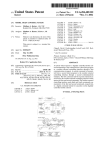
FIG. 1 is a block diagram of an exemplary embodi
ment of a model train control system.
[0014]
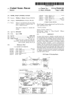
FIG. 2 is a more detailed block diagram of the
model train control system of FIG. 1 including external
device control logic.
[0015] FIG. 3 is a block diagram of the external device
control logic of FIG. 2.
DETAILED DESCRIPTION OF THE
PREFERRED EMBODIMENT
[0016] Referring to FIG. 1, a model train control system
10 includes a communications transport 12 interconnecting
a client program 14 and a resident external controlling
[0018] Incorporating a communications transport 12
between the client program(s) 14 and the resident external
controlling interface 16 permits multiple operators of the
model railroad at locations distant from the physical model
railroad and each other. In the environment of a model
railroad club where the members want to simultaneously
control devices of the same model railroad layout, which
preferably includes multiple trains operating thereon, the
operators each provide commands to the resistant external
controlling interface, and hence the model railroad.
[0019] The manner in which commands are executed for
the model railroad under COM and DCOM may be as
follows. The client program 14 makes requests in a syn
chronous manner using COM/DCOM to the resident exter
nal interface controller 16. The synchronous manner of the
request is the technique used by COM and DCOM to
execute commands. The communications transport 12 pack
ages the command for the transport mechanism to the
resident external controlling interface 16. The resident exter
nal controlling interface 16 then passes the command to the
digital command stations 18 which in turn executes the
command. After the digital command station 18 executes the
command an acknowledgement is passed back to the resi
Aug. 15, 2002
US 2002/01 1 1723 A1
dent external controlling interface 16 Which in turn passes an
acknowledgement to the client program 14. Upon receipt of
the acknowledgement by the client program 14, the com
munications transport 12 is again available to accept another
command. The train control system 10, Without more, per
mits execution of commands by the digital command sta
tions 18 from multiple operators, but like the DigiToys
Systems’ softWare the execution of commands is sloW.
[0020] The present inventor came to the realiZation that
unlike traditional distributed systems Where the commands
passed through a communications transport are executed
nearly instantaneously by the server and then an acknoWl
edgement is returned to the client, the model railroad appli
cation involves the use of extremely sloW real-time inter
faces betWeen the digital command stations and the devices
of the model railroad. The present inventor came to the
further realiZation that in order to increase the apparent
speed of execution to the client, other than using high-speed
communication interfaces, the resident external controller
interface 16 should receive the command and provide an
acknoWledgement to the client program 12 in a timely
manner before the execution of the command by the digital
command stations 18. Accordingly, the execution of com
command processor 100 retrieves such information from the
local database storage 102 and provides the information to
an asynchronous response processor 106. The asynchronous
response processor 106 then provides a response to the client
program 14 indicating the state of the device and releases the
communications transport 12 for the next command.
[0022] The asynchronous command processor 100 also
veri?es, using the con?guration information in the local
database storage 102, that the command received is a
potentially valid operation. If the command is invalid, the
asynchronous command processor 100 provides such infor
mation to the asynchronous response processor 106, Which
in turn returns an error indication to the client program 14.
[0023] The asynchronous command processor 100 may
determine that the necessary information is not contained in
the local database storage 102 to provide a response to the
client program 14 of the device state or that the command is
a valid action. Actions may include, for example, an increase
in the train’s speed, or turning on/off of a device. In either
case, the valid unknoWn state or action command is pack
face 16 to the digital command stations 18 occur in a
aged and forWarded to the command queue 104. The pack
aging of the command may also include additional infor
mation from the local database storage 102 to complete the
client program 14 request, if necessary. Together With pack
aging the command for the command queue 104, the asyn
synchronous manner, such as a ?rst-in-?rst-out manner. The
chronous command processor 100 provides a command to
mands provided by the resident external controlling inter
COM and DCOM communications transport 12 betWeen the
client program 14 and the resident external controlling
interface 16 is operated in an asynchronous manner, namely
providing an acknoWledgement thereby releasing the com
munications transport 12 to accept further communications
prior to the actual execution of the command. The combi
nation of the synchronous and the asynchronous data com
munication for the commands provides the bene?t that the
operator considers the commands to occur nearly instanta
the asynchronous request processor 106 to provide a
response to the client program 14 indicating that the event
has occurred, even though such an event has yet to occur on
the physical railroad layout.
[0024] As such, it can be observed that Whether or not the
command is valid, Whether or not the information requested
by the command is available to the asynchronous command
processor 100, and Whether or not the command has
neously While permitting the resident external controlling
executed, the combination of the asynchronous command
interface 16 to verify that the command is proper and cause
the commands to execute in a controlled manner by the
processor 100 and the asynchronous response processor 106
both veri?es the validity of the command and provides a
response to the client program 14 thereby freeing up the
communications transport 12 for additional commands.
Without the asynchronous nature of the resident external
controlling interface 16, the response to the client program
digital command stations 18, all Without additional high
speed communication netWorks. Moreover, for traditional
distributed softWare execution there is no motivation to
provide an acknoWledgment prior to the execution of the
command because the command executes quickly and most
commands are sequential in nature. In other Words, the
execution of the next command is dependent upon proper
execution of the prior command so there Would be no
motivation to provide an acknoWledgment prior to its actual
execution. It is to be understood that other devices, such as
digital devices, may be controlled in a manner as described
for model railroads.
[0021]
Referring to FIG. 2, the client program 14 sends a
command over the communications transport 12 that is
received by an asynchronous command processor 100. The
asynchronous command processor 100 queries a local data
base storage 102 to determine if it is necessary to package
14 Would be, in many circumstances, delayed thereby result
ing in frustration to the operator that the model railroad is
performing in a sloW and painstaking manner. In this man
ner, the railroad operation using the asynchronous interface
appears to the operator as nearly instantaneously responsive.
[0025] Each command in the command queue 104 is
fetched by a synchronous command processor 110 and
processed. The synchronous command processor 110 que
ries a controller database storage 112 for additional infor
mation, as necessary, and determines if the command has
already been executed based on the state of the devices in the
controller database storage 112. In the event that the com
mand has already been executed, as indicated by the con
a command to be transmitted to a command queue 104. The
troller database storage 112, then the synchronous command
local database storage 102 primarily contains the state of the
devices of the model railroad, such as for example, the speed
of a train, the direction of a train, Whether a draW bridge is
processor 110 passes information to the command queue 104
that the command has been executed or the state of the
up or doWn, Whether a light is turned on or off, and the
the information from the command cue 104 and provides a
suitable response to the client program 14, if necessary, and
con?guration of the model railroad layout. If the command
received by the asynchronous command processor 100 is a
query of the state of a device, then the asynchronous
device. The asynchronous response processor 106 fetches
updates the local database storage 102 to re?ect the updated
status of the railroad layout devices.
Aug. 15, 2002
US 2002/01 1 1723 A1
[0026] If the command fetched by the synchronous com
mand processor 110 from the command queue 104 requires
execution by external devices, such as the train engine, then
the command is posted to one of several external device
control logic 114 blocks. The external device control logic
114 processes the command from the synchronous command
processor 110 and issues appropriate control commands to
the interface of the particular external device 116 to execute
clients to communicate With different devices. In other
Words, the command queue 104 permits the proper execu
tion in the cases of: (1) one client to many devices, (2) many
clients to one device, and (3) many clients to many devices.
the command on the device and ensure that an appropriate
response Was received in response. The external device is
vendors have at least three different techniques for commu
preferably a digital command control device that transmits
digital commands to decoders using the train track. There
are several different manufacturers of digital command
stations, each of Which has a different set of input com
mands, so each external device is designed for a particular
digital command station. In this manner, the system is
compatible With different digital command stations. The
digital command stations 18 of the external devices 116
provide a response to the external device control logic 114
Which is checked for validity and identi?ed as to Which prior
command it corresponds to so that the controller database
storage 112 may be updated properly. The process of trans
mitting commands to and receiving responses from the
external devices 116 is sloW.
[0027] The synchronous command processor 110 is noti
?ed of the results from the external control logic 114 and, if
appropriate, forWards the results to the command queue 104.
The asynchronous response processor 100 clears the results
from the command queue 104 and updates the local database
storage 102 and sends an asynchronous response to the
client program 14, if needed. The response updates the client
program 14 of the actual state of the railroad track devices,
if changed, and provides an error message to the client
program 14 if the devices actual state Was previously
improperly reported or a command did not execute properly.
[0028]
The use of tWo separate database storages, each of
Which is substantially a mirror image of the other, provides
a performance enhancement by a fast acknowledgement to
the client program 14 using the local database storage 102
and thereby freeing up the communications transport 12 for
additional commands. In addition, the number of commands
forWarded to the external device control logic 114 and the
external devices 116, Which are relatively sloW to respond,
is minimiZed by maintaining information concerning the
state and con?guration of the model railroad. Also, the use
of tWo separate database tables 102 and 112 alloWs more
ef?cient multi-threading on multi-processor computers.
[0029] In order to achieve the separation of the asynchro
nous and synchronous portions of the system the command
queue 104 is implemented as a named pipe, as developed by
Microsoft for WindoWs. The queue 104 alloWs both portions
to be separate from each other, Where each considers the
other to be the destination device. In addition, the command
queue maintains the order of operation Which is important to
proper operation of the system.
[0030]
The use of a single command queue 104 alloWs
multiple instantrations of the asynchronous functionality,
With one for each different client. The single command
queue 104 also alloWs the sharing of multiple devices,
multiple clients to communicate With the same device
(locally or remote) in a controlled manner, and multiple
[0031]
The present inventor came to the realiZation that
the digital command stations provided by the different
nicating With the digital decoders of the model railroad set.
The ?rst technique, generally referred to as a transaction
(one or more operations), is a synchronous communication
Where a command is transmitted, executed, and a response
is received therefrom prior to the transmission of the next
sequentially received command. The DCS may execute
multiple commands in this transaction. The second tech
nique is a cache With out of order execution Where a
command is executed and a response received therefrom
prior to the execution of the next command, but the order of
execution is not necessarily the same as the order that the
commands Were provided to the command station. The third
technique is a local-area-netWork model Where the com
mands are transmitted and received simultaneously. In the
LAN model there is no requirement to Wait until a response
is received for a particular command prior to sending the
next command. Accordingly, the LAN model may result in
many commands being transmitted by the command station
that have yet to be executed. In addition, some digital
command stations use tWo or more of these techniques.
[0032] With all these different techniques used to commu
nicate With the model railroad set and the system 10 pro
viding an interface for each different type of command
station, there exists a need for the capability of matching up
the responses from each of the different types of command
stations With the particular command issued for record
keeping purposes. Without matching up the responses from
the command stations, the databases can not be updated
properly.
[0033] Validation functionality is included Within the
external device control logic 114 to accommodate all of the
different types of command stations. Referring to FIG. 3, an
external command processor 200 receives the validated
command from the synchronous command processor 110.
The external command processor 200 determines Which
device the command should be directed to, the particular
type of command it is, and builds state information for the
command. The state information includes, for example, the
address, type, port, variables, and type of commands to be
sent out. In other Words, the state information includes a
command set for a particular device on a particular port
device. In addition, a copy of the original command is
maintained for veri?cation purposes. The constructed com
mand is forWarded to the command sender 202 Which is
another queue, and preferably a circular queue. The com
mand sender 202 receives the command and transmits
commands Within its queue in a repetitive nature until the
command is removed from its queue. A command response
processor 204 receives all the commands from the command
stations and passes the commands to the validation function
206. The validation function 206 compares the received
Aug. 15, 2002
US 2002/01 1 1723 A1
command against potential commands that are in the queue
of the command sender 202 that could potentially provide
-continued
such a result. The validation function 206 determines one of
Table of contents
four potential results from the comparison. First, the results
could be simply bad data that is discarded. Second, the
results could be partially executed commands Which are
3.4
KamProgram
KamProgramGetMode
KamProgramGetStatus
KamProgramReadCV
KamProgramCV
KamProgramReadDecoderToDataBase
KamProgramDecoderFromDataBase
likeWise normally discarded. Third, the results could be
valid responses but not relevant to any command sent. Such
a case could result from the operator manually changing the
state of devices on the model railroad or from another
external device, assuming a shared interface to the DCS.
Accordingly, the results are validated and passed to the
result processor 210. Fourth, the results could be valid
Commands to program con?guration variables
35
Commands to control all decoder types
KamDecoderGetMaxModels
KamDecoderGetModelName
KamDecoderSetModelToObj
responses relevant to a command sent. The corresponding
KamDecoderGetMaxAddress
KamDecoderChangeOldNeWAddr
command is removed from the command sender 202 and the
results passed to the result processor 210. The commands in
the queue of the command sender 202, as a result of the
validation process 206, are retransmitted a predetermined
number of times, then if error still occurs the digital com
mand station is reset, Which if the error still persists then the
command is removed and the operator is noti?ed of the
KamDecoderMovePort
KamDecoderGetPort
KamDecoderCheckAddrInUse
KamDecoderGetModelFromObj
KamDecoderGetModelFacility
KamDecoderGetObj Count
KamDecoderGetObjAtIndex
KamDecoderPutAdd
KamDecoderPutDel
KamDecoderGetMfgName
KamDecoderGetPoWerMode
KamDecoderGetMaxSpeed
APPLICATION PROGRAMMING INTERFACE
3.6
[0035]
Building your oWn visual interface to a model
railroad Copyright 1992-1998 KAM Industries.
[0036] Computer Dispatcher, Engine Commander, The
Conductor, Train Server, and Train Tools are Trademarks of
KAM Industries, all Rights Reserved.
[0037] Questions concerning the
product can be
KamEngPutFunctio nName
KamEngGetConsistMax
KamEngPutConsistParent
EMAILED to:
[email protected]
[0038] You can also mail questions to:
KamEngPutCo ns istChild
3_7
[0039] KAM Industries
[0040]
Commands to control locomotive decoders
KamEngGetSpeed
KamEngPutSpeed
KamEngGetSpeedSteps
KamEngPutSpeedSteps
KamEngGetFunction
KamEngPutFunction
KamEngGetFunctionMax
KamEngGetName
KamEngPutName
KamEngGetFunctionName
[0034] Train ToolsTM Interface Description
2373 NW 185th Avenue Suite 416
[0041] Hillsboro, Oregon 97124
[0042] Fax—(503) 291-1221
KamEngPutConsistRemoveObj
Commands to control accessory decoders
KamAccGetFunction
KamAccGetFunctionAll
KamAccPutFunction
KamAccPutFunctionAll
KamAccGetFunctionMax
KamAccGetName
KamAccPutName
KamAccGetFunctionName
KamAccPutFunctionName
KamAccRegFeedback
KamAccRegFeedbackAll
Table of contents
3.8
KamAccDelFeedback
KamAccDelFeedbackAll
Commands to control the command station
1.
OVERVIEW
KamOp rPutTurnOnS tation
1.1
System Architecture
2.
TUTORIAL
2.1
Visual BASIC Throttle Example Application
KamOprPutStartStation
KamOprPutClearStation
KamOprPutStopStation
KamOprPutPoWerOn
KamOprPutPoWerOff
KamOprPutHardReset
KamOprPutEmergencyStop
KamOprGetStationStatus
2.2
Visual BASIC Throttle Example Source Code
3.
3.1
IDL COMMAND REFERENCE
Introduction
3.2
Data Types
3.3
Commands to access the server con?guration variable
database
KamCVGetValue
KamCVPutValue
KamCVGetEnable
KamCVPutEnable
KamCVGetName
KamCVGetMinRegister
KamCVGetMaxRegister
3.9
Commands to con?gure the command station
communication port
KamPortPutCon?g
KamPortGetCon?g
KamPortGetName
KamPortPutMapController
KamPortGetMaxLogPorts
KamPortGetMaxPhysical
Aug. 15, 2002
US 2002/01 1 1723 A1
[0056]
3.10
3.11
are assigned to. Train ServerT Interface supports a
Table of contents
limited number of logical ports. You can also think of
ports as mapping to a command station type. This
Commands that control command flow to
the command station
KamCmdConnect
KamCmdDisConnect
KamCmdCommand
Cab Control Commands
KamCabGetMessage
KamCabPutMessage
3.12
Ports—>These are logical ids where Decoders
-continued
KamCabGetCabAddr
KamCabPutAddrToCab
Miscellaneous Commands
KamMiscGetErrorMsg
KamMiscGetClockTime
KamMiscPutClockTime
KamMiscGetInterfaceVersion
KamMiscSaveData
KamMiscGetControllerName
KamMiscGetControllerNameAtPort
KamMiscGetCommandStationValue
KamMiscSetCommandStationValue
KamMiscGetCommandStationIndex
KamMiscMaxControllerID
KamMiscGetControllerFacility
allows you to move decoders between command
station without losing any information about the
decoder
[0057]
DevicesQThese are communications chan
nels con?gured in your computer.
[0058]
You may have a single device (com1) or
multiple devices
[0059] (COM 1—COM8, LPT1, Other). You are
required to map a port to a device to access a
command station. Devices start from ID 0Qmax id
(FYI; devices do not necessarily have to be serial
channel. Always check the name of the device before
you use it as well as the maximum number of devices
supported.
[0060] The Command
[0061] EngCmd.KamPortGetMaxPhysical (1Max
Physical, 1Serial, 1Parallel) provides means that . . .
1MaxPhysical=1Serial+1Parallel+10ther
[0043] I. OVERVIEW
[0044] This document is divided into two sections, the
Tutorial, and the IDL Command Reference. The tutorial
shows the complete code for a simple Visual BASIC pro
gram that controls all the major functions of a locomotive.
This program makes use of many of the commands
described in the reference section. The IDL Command
Reference describes each command in detail.
[0045] I. TUTORIAL
[0046] A. Visual BASIC Throttle Example Application
[0047] The following application is created using the
Visual BASIC source code in the next section. It controls all
major locomotive functions such as speed, direction, and
[0062]
Controller—These are command the com
mand station like LENZ, Digitrax
[0063]
Northcoast, EasyDCC, Marklin . . . It is rec
ommend that you check the command station ID
before you use it.
[0064] Errors—All commands return an error sta
tus. If the error value is non Zero, then the other
return arguments are invalid. In general, non Zero
errors means command was not executed. To get
the error message, you need to call KamMiscEr
rorMessage and supply the error number
[0065] To Operate your layout you will need to
perform a mapping between a Port (logical refer
auxiliary functions.
ence), Device (physical communications channel)
[0048] A. Visual BASIC Throttle Example Source Code
Copyright 1998, KAM Industries. All rights reserved.
to work. All references uses the logical device as the
reference device for access.
[0049]
This is a demonstration program showing the
integration of VisualBasic and Train Server(tm)
interface. You may use this application for non
commercial usage.
[0050] $Date: $
[0051] $Author1$
and a Controller (command station) for the program
[0066] Addresses used are an object reference. To use
an address you must add the address to the command
station using KamDecoderPutAdd . . . One of the
return values from this operation is an object refer
ence that is used for control.
[0067] We need certain variables as global objects;
since the information is being used multiple times
[0052] $Revision: $
[0068] Dim iLogicalPort, icontroller, iComPort
[0053] $Log: $
[0054] Engine Commander, Computer Dispatcher,
[0069] Dim iPortRate, iPortParity, iPortStop, iPortRe
trans, iPortWatchdog, iPortFlow, iPortData
Train Server, Train Tools, The Conductor and
[0070] Dim 1Engineobject As Long, iDecoderClass As
kamind are registered Trademarks of KAM Indus
Integer,
[0071] iDecoderType As Integer
tries. All rights reserved.
[0055]
This ?rst command adds the reference to the
Train ServerT Interface object Dim EngCmdAs New
EngComIfc Engine Commander uses the term Ports,
Devices and Controllers
[0072] Dim 1MaxController As Long
[0073] Dim 1MaxLogical As Long, lMaxPhysical As
Long, 1MaxSerial As Long, 1MaxParallel As Long
Aug. 15, 2002
US 2002/01 1 1723 A1
[0074]
-continued
U696*9696969696************************
‘Form load function
‘— Turn of the initial buttons
‘— Set he interface information
'9696969696969696************************
Private Sub Formiload()
Dim strVer As String, strCom As String, strCntrl As
String
‘
‘
‘
‘
‘
‘
‘
‘
0:
1:
2:
3:
4:
5:
6:
7:
//
//
//
//
//
//
//
//
Baud
Baud
Baud
Baud
Baud
Baud
Baud
Baud
rate
rate
rate
rate
rate
rate
rate
rate
is
is
is
is
is
is
is
is
300
1200
2400
4800
9600
14.4
16.4
19.2
iPortRate = 4
‘Get the interface version information
‘ Parity values 0-4 —> no, odd, even, mark,
space
SetButtonState (False)
iPortParity = 0
Dim iError As Integer
iError = EngCmd.KamMiscGetInterfaceVersion(strVer)
‘ Stop bits 0,1,2 —> 1, 1.5, 2
If (iError) Then
MsgBoX ((“Train Server not loaded. Check
iPortRetrans = 10
iPortStop = 0
iPortWatchdog = 2048
DCOM-95”))
iPortFloW = 0
iLogicalPort = 0
LogPort.Caption = iLogicalPort
‘ Data bits 0 — > 7 Bits, 1—> 8 bits
ComPort.Caption = “7??”
Controller.Caption = “Unknown”
iPortData = 1
Else
MsgBoX ((“Simulation(COM1) Train Server —— ” &
‘Display the port and controller information
iError = EngCmd.KamPortGetMaXLogPorts(lMaXLogical)
iError = EngCmd.KamPortGetMaXPhysical(lMaXPhysical,
lMaXSerial, lMaXParallel)
strVer))
‘9696969696969696969696969696969696*********************
‘ Get the port name and do some checking . . .
‘Con?guration information; Only need to
iError = EngCmd.KamPortGetName(iComPort, strCom)
change these values to use a different
controller
.
.
.
‘96*9696**********************************
‘
‘
‘
‘
‘
UNKNOWN
SIMULAT
LENZflX
LENZiZX
DIGITiDT200
0
1
2
3
4
//
//
//
//
//
Unknown control type
Interface simulator
Lenz serial support module
Lenz serial support module
DigitraX direct drive
support using DT200
‘ DIGITiDCS100
5 // DigitraX direct drive
‘ MASTERSERIES
6 // North Coast engineering
master Series
7 // System One
8 // RAMFIXX system
9 // Dynatrol system
support using DCS100
‘ SYSTEMONE
‘ RAMFIX
‘ DYNATROL
‘ Northcoast binary
10 // North Coast binary
‘ SERIAL
11 // NMRA Serial
‘ EASYDCC
‘ MRK6050
12 // NMRA Serial interface
13 // 6050 Marklin interface
‘ MRK6023
14 // 6023 Marklin hybrid
‘ ZTC
‘ DIGITfPRl
15 // ZTC Systems ltd
16 // DigitraX direct drive
‘ DIRECT
17 // Direct drive interface
interface
(AC and DC)
interface (AC)
support using PR1
routine
‘*96’69696’696’696969696*9‘****9‘*9‘****9‘*9‘******************************
iLogicalPort = 1 ‘Select Logical port 1 for communications
iController = 1 ‘Select controller from the list above.
iComPort = 0 ‘ use COM1; 0 means com1 (DigitraX must
use Com1 or Com2)
‘DigitraX Baud rate requires 16.4K!
SetError (iError)
If (iComPort > lMaXSerial) Then MsgBoX (“Com port
our of range”)
iError =
EngCmd.KamMiscGetControllerName(iController,
strCntrl)
If (iLogicalPort > lMaXLogical) Then MsgBoX
(“Logical port out of range”)
SetError (iError)
End If
‘Display values in Throttle . .
LogPort.Caption = iLogicalPort
ComPort.Caption = strCom
Controller.Caption = strCntrl
End Sub
I******************************
‘Send Command
‘Note:
‘ Please folloW the command order. Order is important
‘ for the application to Work!
U696*96*9696969696********************
Private Sub CommandiClick()
‘Send the command from the interface to the command
station, use the engineObject
Dim iError, iSpeed As Integer
If Not Connect.Enabled Then
‘TrainTools interface is a caching interface.
‘This means that you need to set up the CV’s or
‘other operations ?rst; then eXecute the
‘command.
iSpeed = Speed.TeXt
iError =
EngCmd.KamEngPutFunction (lEngineObject, 0, F0.Value)
iError =
EngCmd.KamEngPutFunction(lEngineObject, 1,
F1.Value)
‘Most COM ports above Com2 do not
iError =
‘support 16.4K. Check With the
EngCmd.KamEngPutFunction(lEngineObject, 2,
‘manufacture of your smart com card
F2.Value)
‘for the baud rate. Keep in mind that
‘Dumb com cards With serial port
EngCmd.KamEngPutFunction(lEngineObject, 3,
‘support Com1 — Com4 can only support
F3.Value)
iError =
‘2 com ports (like com1/com2
iError = EngCmd.KamEngPutSpeed(lEngineObject,
‘or com3/com4)
iSpeed, Direction.Value)
‘If you change the controller, do not
‘forget to change the baud rate to
If iError = 0 Then iError =
‘match the command station. See your
‘user manual for details
1*************9‘96******96*?‘**********************************
EngCmd.KamCmdCommand(lEngineObject)
SetError (iError)
End If
End Sub
Aug. 15, 2002
US 2002/01 1 1723 A1
—continued
—continued
U696*96969696969696********************
iDebugMode = 130
‘Connect Controller
iValue = Value.Text‘ Display value for reference
U696*$6**************************
iError = EngCmd.KamPortPutCon?g(iLogicalPort, 7, iDebug,
iValue)‘ setting PORTiDEBUG
Private Sub ConnectiClick()
Dim iError As Integer
‘These are the index values for setting up the port
PORTiRETRANS
PORTiRATE
PORTLPARITY
PORTiSTOP
PORTLWATCHDOG
PORTiFLOW
PORTLDATABITS
PORTiDEBUG
PORTLPARALLEL
0
1
2
3
4
5
6
7
8
//
//
//
//
//
//
//
//
//
Retrans
Retrans
Retrans
Retrans
Retrans
Retrans
Retrans
Retrans
Retrans
index
index
index
index
index
index
index
index
index
‘These are the index values for setting up the
port for use
‘ PORTiRETRANS
‘
‘
‘
‘
‘
‘
‘
‘
station and Controller
iError = EngCmd.KamPortPutMapController(iLogicalPort,
for use
‘
‘
‘
‘
‘
‘
‘
‘
‘
‘NoW map the Logical Port, Physical device, Command
PORTiRATE
PORTLPARITY
PORTiSTOP
PORTiWATCHDOG
PORTiFLOW
PORTLDATABITS
PORTLDEBUG
PORTiPARALLEL
0
1
2
3
4
5
6
7
8
//
//
//
//
//
//
//
//
//
Retrans
Retrans
Retrans
Retrans
Retrans
Retrans
Retrans
Retrans
Retrans
index
index
index
index
index
index
index
index
index
iError = EngCmd.KamPortPutCon?g(iLogicalPort, 0,
iController, iComPort)
iError = EngCmd.KamCmdConnect(iLogicalPort)
iError = EngCmd.KamOprPutTurnOnStation(iLogicalPort)
If (iError) Then
SetButtonState (False)
Else
SetButtonState (True)
End If
SetError (iError) ‘Displays the error message and error
number
End Sub
U696*96*9696969696********************
‘Set the address button
UK*****************************
Private Sub DCCAddriClick()
Dim iAddr, iStatus As Integer
‘All addresses must be match to a logical port to
operate
iDecoderType = 1 ‘ Set the decoder type to an NMRA
baseline decoder (1 — 8 reg)
iDecoderClass = 1 ‘ Set the decoder class to Engine
iPortRetrans, 0) ‘ setting PORTLRETRANS
decoder (there are only tWo classes of decoders;
iError = EngCmd.KamPortPutCon?g(iLogicalPort, 1,
Engine and Accessory
iPortRate, 0) ‘ setting PORTiRATE
‘Once We make a connection, We use the lEngineObject
iError = EngCmd.KamPortPutCon?g(iLogicalPort, 2,
‘as the reference object to send control information
iPortParity, 0) ‘ setting PORTLPARITY
If (Address.Text > 1) Then
iError = EngCmd.KamPortPutCon?g(iLogicalPort, 3,
iPortStop, 0) ‘ setting PORTiSTOP
iError = EngCmd.KamPortPutCon?g(iLogicalPort, 4,
iPortWatchdog, 0) ‘ setting PORTLWATCHDOG
iError = EngCmd.KamPortPutCon?g(iLogicalPort, 5,
iPortFloW, 0) ‘ setting PORTiFLOW
iError = EngCmd.KamPortPutCon?g(iLogicalPort, 6,
iPortData, 0) ‘ setting PORTLDATABITS
‘ We need to set the appropriate debug mode for display . .
‘ this command can only be sent if the folloWing is true
‘ —Controller is not connected
‘ —port has not been mapped
‘ —Not share Ware version of application (Shareware
alWays set to 130)
‘ Write Display Log Debug
‘ File Win Level Value
‘ 1 + 2 + 4 = 7 —> LEVEL1 —— put packets into
iStatus = EngCmd.KamDecoderPutAdd(Address.Text,
iLogicalPort, iLogicalPort, 0,
iDecoderType, lEngineObject)
SetError (iStatus)
If (lEngineObject) Then
Command.Enabled = True ‘turn on the control
(send) button
Throttle.Enabled = True ‘ Turn on the throttle
Else
MsgBox (“Address not set, check error message”)
End If
Else
MsgBox (“Address must be greater then 0 and
less then 128”)
End If
End Sub
v*******************
‘Disconenct button
queues
‘ 1 + 2 + 8 = 11 —> LEVEL2 —— Status messages
'96969696969696969696969696969696969696
‘
Private Sub DisconnectiClick()
send to WindoW
Dim iError As Integer
‘ 1 + 2 + 32 = 35 —> LEVEL4 —— All system
iError = EngCmd.KamCmdDisConnect(iLogicalPort)
‘
SetError (iError)
SetButtonState (False)
semaphores/critical sections
‘ 1 + 2 + 64 = 67 -> LEVELS -- detailed
‘
debugging information
‘ 1 + 2 + 128 = 131 —> COMMONLY —— Read comm Write
comm ports
‘You probably only Want to use values of 130. This Will
‘give you a display What is read or Written to the
‘controller. If you Want to Write the information to
‘disk, use 131. The other information is not valid for
This does effect the performance of you
system; 130 is a save value for debug
display. AlWays set the key to 1, a value
‘
‘
2.
of 0 Will disable debug
The Digitrax control codes displayed are
encrypted. The information that you
determine from the control codes is that
information is sent (S) and a response is
‘
v**********************
‘Display error message
l**********************
Private Sub SetError(iError As Integer)
Dim sZError As String
Dim iStatus
‘ This shoWs hoW to retrieve a sample error message
‘end users.
‘ Note: 1.
End Sub
received (R)
from the interface for the status received.
iStatus = EngCmd.KamMiscGetErrorMsg(iError, sZError)
ErrorMsg.Caption = sZError
Result.Caption = Str(iStatus)
End Sub
'9696************************
‘Set the Form button state
‘9696969696*********************
Private Sub SetButtonState(iState As Boolean)
‘We set the state of the buttons; either connected
or disconnected
Aug. 15, 2002
US 2002/01 1 1723 A1
[0078] A. Data Types
-continued
If (iState) Then
[0079] Data is passed to and from the IDL interface using
a several primitive data types. Arrays of these simple types
Connect.Enabled = False
Disconnect.Enabled = True
ONCrnd.Enabled = True
OffCmdEnabled = True
DCCAddr.Enabled = True
UpDoWnAddress.Enabled = True
'NoW We check to see if the Engine Address has been
‘set; if it has We enable the send button
are also used. The exact type passed to and from your
program depends on the programming language your are
using.
[0080] The folloWing primitive data types are used:
If (lEngineObject > 0) Then
Command.Enabled = True
Throttle.Enabled = True
IDL Type
BASIC Type C++ Type Java Type Description
short
short
short
short
int
int
int
int
Signed integer
Connect.Enabled = True
BSTR
BSTR
BSTR
BSTR
Text string
Disconnect.Enabled = False
long
long
long
long
Unsigned 32 bit value
Else
Command.Enabled = False
Throttle.Enabled = False
End If
Else
Command.Enabled = False
Short signed integer
ONCrnd.Enabled = False
OffCmdEnabled = False
DCCAddr.Enabled = False
UpDoWnAddress.Enabled = False
Address
Name ID
CV Range
Valid CV’s
Functions
Range
Speed
0
None
None 2
1-99
14
Throttle.Enabled = False
End If
End Sub
Steps
v*******************
'PoWer Off function
NMRA
196969696969696969696969696969696969696
Compatible
Private Sub OffCmdiClickO
Dim iError As Integer
Baseline
1
1-8
1-8 9
1-127
14
iError = EngCmd.KamOprPutPoWerOff(iLogicalPort)
Extended
2
1-106
1-9, 17,
1-10239
14,28,
SetError (iError)
18, 19, 23,
End Sub
128
24, 29, 30,
v******************
'PoWer On function
49, 66-95
'969696969696969696969696969696969696
9
Private Sub ONCmdiClickO
Dim iError As Integer
All Mobile
3
1-106
1-106 9
1-10239
iError = EngCmd.KamOprPutPoWerOn(iLogicalPort)
14,28,
128
SetError (iError)
End Sub
1************************
Name ID
CV Range
Valid CV’s
Functions
Address Range
‘Throttle slider control
'96***********************
Private Sub ThrottleiClickO
If (lEngineObject) Then
If (Throttle.Value > 0) Then
Accessory
4
513-593
513-593 8
0-511
All Stationary
5
513-1024
513-1024 8
O-511
Speed.Text = Throttle.Value
End If
End If
End Sub
[0075]
[0081] A long /DecoderObject/D value is returned by the
KamDecoderPutAdd call if the decoder is successfully reg
istered With the server. This unique opaque ID should be
used for all subsequent calls to reference this decoder.
I. IDL COMMAND REFERENCE
[0076] A. Introduction
[0077] This document describes the IDL interface to the
KAM Industries Engine Commander Train Server. The
[0082] A. Commands to access the server con?guration
variable database
of controlling your railroad. You Write simple, front end
[0083] This section describes the commands that access
the server con?guration variables (CV) database. These CVs
are stored in the decoder and control many of its character
istics such as its address. For ef?ciency, a copy of each CV
value is also stored in the server database. Commands such
programs in a variety of languages such as BASIC, Java, or
C++ to provide the visual interface to the user While the
server handles the details of communicating With the com
mand station, etc.
as KamCVGetValue and KamCVPutValue communicate
only With the server, not the actual decoder. You then use the
programming commands in the next section to transfer CVs
to and from the decoder.
Train Server DCOM server may reside locally or on a
network node This server handles all the background details
Aug. 15, 2002
US 2002/01 1 1723 A1
10
OKamCVGetValue
Parameter List
lDecoderObjectID
Type
pCVVale int"
1
Range
long
Direction
1
3
Out
In
Description
Decoder object ID
Pointer to CV value
Opaque object ID handle returned by
KamDecoderPutAdd.
2 Rangle is 1-1-1024. Maximum CV for this decoder is
given by KamCVGetMaxRegister.
3
CV Value pointed to has a range of 0 to 255.
Return Value
Type
Range
iError short
1
Error ?ag
1
Description
iError = 0 for success. Nonzero is an error number
(see KamMiscGetErrorMsg). KamCVGetValue takes the
decoder object ID and con?uration variable (CV) number
as parameters. It sets the memory of the con?guration
variable.
0KamCVPutValue
Parameter List
lDecoderObjectID
Type
Range
long
Direction
1
iCVRegint
1-1024
2
In
Description
In Decoder object ID
CV register
iCVValue
int
0—255
In
CV value
1
Opaque object ID handle returned by
KamDecoderPutAdd.
2 Maximum CV is 1024. Maximum CV for this decoder is
given by KamCVGetMaxRegister.
Return Value
Type
Range
iError short
1
Error ?ag
1
Description
iError = 0 for success. Nonzero is an error number
(see KamMiscGetErrorMsg).
KamCVPutValue takes the decoder object ID, con?guration
variable (CV) number, and a neW CV value as parameters.
It sets the server copy of the speci?ed deocder CV to
iCVValue.
OKamCVGetEnable
Parameter List
Type
lDecoderObjectID
iCVRegint
pEnable
1
1-1024
int"
Range
Direction
long
1
In
Description
2
3
In
Out
CV number
Pointer to CV bit mask
Decoder object ID
Opaque object ID handle returned by
KamDecoderPutAdd.
2 Maximum CV is 1024. Maximum CV for this decoder is
given by KamCVGetMaxRegister.
3
0x0001 - SERTLCVLINUSE 0x0002 - SETiCViReadiDIRTY
0x0004 - SETLCVLERRORLWRITE
SETiCViERRORiREAD
0x0010 - SETLCVLERRORLWRITE
Return Value
Type
Range
iError short
1
Error ?ag
1
Description
iError = 0 for success. Nonzero is an error number
(see KamMiscGetErrorMsg). KamCVGetEnable takes the
decoder object ID, con?guration variables (CV) number.
and a pointer to store the enable ?ag as parameters. It
sets the location pointed to by pEnable.
0KamCVPutEnable
Parameter List
lDecoderObjectID
Type
iCVRegint
iEnableint
1
1-1024
3
Range
long
Direction
1
2
In
Im
CV number
CV bit mask
In
Description
Decoder object ID
Opaque object ID handle returned by
KamDecoderPutAdd.
2 Maximum CV is 1024. Maximum CV for this decoder is
given by KamCVGetMaxRegister.
3
0x0001 — SETiCViINUSE 0x002 — SETiCViREADiDIRTY
0x0004 — SETiCViWRITEiDIRTY 0x0008 —
SETiCViERRORiREAD
0x0010 — SETiCViERRORiWRITE
Return Value
Type
Range
iError short
1
Error ?ag
1
Description
iError = 0 for success. Nonzero is an error number
(see KamMiscGetErrorMsg).
KamCVPutEnable takes the decoder object ID, con?guration
variable (CV) number, and a neW enable state as
parameters. It sets the server copy of the CV bit mask
to iEnable.
Aug. 15, 2002
US 2002/01 1 1723 A1
11
-continued
OKamCVGetName
Parameter List
Type
Range
iCV int
pbsCVNameString
1-1024
In
CV number
BSTR * Out
1
1
Direction
Description
Pointer to CV
name string
EXact return type depends on language. It is
Cstring * for C++. Empty string on error.
Return Value
Type
Range
iError short
1
Error flag
1
Description
iError = 0 for success. Nonzero is an error number
(see KamMiscGetErrorMsg).
KamCVGetName takes a con?guration variable (CV) number
as a parameter. It sets the memory pointed to by
pbsCVNameString to the name of the CV as de?ned in NMRA
Recommended Practice RP 9.2.2.
OKamCVGetMinRegister
Parameter List
lDecoderObjectID
Type
Range
long
Direction
1
In
pMinRegister
int *
2
Out
Pointer to min CV
Description
Decoder object ID
register number
1
Opaque object ID handle returned by
KamDecoderPutAdd.
2
Normally 1-1024. 0 on error or if decoder does not
support CVs.
Return Value
Type
Rangle
iError short
1
Error flag
1
Description
iError = 0 for success. Nonzero is an error number
(see KamMiscGetErrorMsg).
KamCVGetMinRegister takes a decoder object ID as a
parameter. It sets the memory pointed to by pMinRegister
to the minimum possible CV register number for the
speci?ed decoder.
OKamCVGetMaXRegister
Parameter List
lDecoderObjectID
Type
pMaXRegister
int *
Range
long
Direction
1
In
Description
Decoder Object ID
2
Out
Pointer to maX CV
register number
1 Opaque object ID handle returned by
KamDecoderPutAdd.
2
Normally 1-1024. 0 on error or if decoder does not
support CVs.
Return Value
Type
Range
iError short
1
Error flag
1
Description
iError = 0 for success. Nonzero is an error number
(see KamMiscGetErrorMsg).
KamCVGetMaXRegister takes a decoder object ID as a
parameter. It sets the memory pointed to by pMaXRegister
to the maXimum possible CV register number for the
speci?ed decoder.
[0084] A. Commands to program con?guration variables
[0085] This section describes the commands read and
Write decoder con?guration variables (CVs). You should
initially transfer a copy of the decoder CVs to the server
using the KamProgramReadDecoderToDataBase command.
You can then read and modify this server copy of the CVs.
Finally, you can program one or more CVs into the decoder
using the KamProgramCV or KamProgramDecoderFrom
DataBase command. Not that you must ?rst enter program
ming mode by issuing the KamProgram command before
any programming can be done.
Aug. 15, 2002
US 2002/01 1 1723 A1
12
OKamProgram
Parameter List
lDecoderObjectID
iProgLogPort
Type
Range
long
1-65535
int
Direction
1
In
2
In
Description
Decoder object ID
Logical
programming
iProgMods int
3
1 Opaque object ID handle returned by
port ID
Programming mode
In
KamDecoderPutAdd.
2 Maximum value for this server given by
KamPortGetMaXLogPorts.
3
O
-
PROGRAMLMODELNONE
1
-
PROGRAMLMODELADDRESS 2
-
PROGRAMLMODELREGISTER
3
-
PROGRAMiMODEiPAGE
4
-
PROGRAMLMODELDIRECT
5
-
DCODELPRGMODELOPSLSHORT
6
-
PROGRAMLMODELOPSLLONG
Return Value
Type
Range
iError short
1
Error ?ag
1
Description
iError = 0 for success. Nonzero is an error number
(see KamMiscGetErrorMsg).
KamProgram take the decoder object ID, logical
programming port ID, and programming mode as parameters.
It changes the command station mode from normal operation
(PROGRAMLMODELNONE) to the speci?ed programming mode.
Once in programming modes, any number of programming
commands may be called. When done, you must call
KamProgram With a parameter of PROGRAMLMODELNONE to
return to normal operation.
OKamProgamGetMode
Parameter List
lDecoderObjectID
iProgLogPort
Type
Range
long
1-65535
int
Direction
1
In
2
In
Description
Decoder object ID
Logical
programming
port ID
piProgMode
1
int * 3
Out
Programming mode
Opaque object ID handle returned by
KamDecoderPutAdd.
2 Maximum value for this server given by
KamPortGetMaXLogPorts.
3
O
-
PROGRAMiMODEiNONE
1
-
PROGRAMLMODELADDRESS 2 -
PROGRAMLMODELREGISTER
3
-
PROGRAMLMODELPAGE
4
-
PROGRAMiMODEiDIRECT
5
-
DCODELPRGMODELOPSLSHORT
6
-
PROGRAMLMODELOPSLLONG
Return Value
Type
Range
iError short
1
Error ?ag
1
Description
iError = 0 for success. Nonzero is an error number
(see KamMiscGetErrorMsg).
KamProgramGetMode take the decoder object ID, logical
programming port ID, and pointer to a place to store
the programming mode as parameters. It sets the memory
pointed to by piProgMode to the present programming mode.
OKamProgramGetStatus
Parameter List
lDecoderObjectID
Type
Range
long
Direction
1
In
iCVRegint
piCVAllStatus
0-1024
int *
2
3
In
CV number
Or’d decoder programming
Out
status
1
Opaque object ID handle returned by
KamDecoderPutAdd.
2 0 returns OR’d value for all CVs. Other values
return status for just that CV.
3
OXOOOl - SETLCVLINUSE
OXOOO2 - SETLCVLREADLDIRTY
OXOOO4 - SETiCViWRITEiDIRTY
OXOOOS - SETLCVLERRORLREAD
OXOOlO - SETLCVLERRORLWRITE
Return Value
Type
Range
iError short
1
Error ?ag
1
Description
iError = 0 for success. Nonzero is an error number
(see KamMiscGetErrorMsg).
KamProgramGetStatus take the decoder object ID and
Description
Decoder object ID
Aug. 15, 2002
US 2002/01 1 1723 A1
13
-continued
pointer to a place to store the OR’d decoder programming
status as parameters. It sets the memory pointed to by
piProgMode to the present programming mode.
OKamProgramReadCV
Parameter List
lDecoderObjectID
Type
Range
long
Direction
1
In
iCVRegint
2
In
CV number
1
Description
Decoder object ID
Opaque object ID handle returned by
KamDecoderPutAdd.
2 Maximum CV is 1024. Maximum CV for this decoder is
given by KamCVGetMaxRegister.
Return Value
Type
Range
iError short
1
Error ?ag
1
Description
iError = 0 for success. Nonzero is an error number
(see KamMiscGetErrorMsg).
KamProgramCV takes the decoder object ID, con?guration
variable (CV) number a parameters. It reads the
speci?ed CV variable value to the server database.
OKamProgramCV
Parameter List
lDecoderObjectID
Type
Range
long
Direction
1
In
iCVRegint
2
In
CV number
iCVValue
int
0-255
In
1
Description
Decoder object ID
CV value
Opaque object ID handle returned by
KamDecoderPutAdd.
2 Maximum CV is 1024. Maximum CV for this decoder is
given by KamCVGetMaxRegister.
Return Value
Type
Range
iError short
1
Error ?ag
1
Description
iError = 0 for success. Nonzero is an error number
(see KamMiscGetErrorMsg).
KamProgramCV takes the decoder object ID, con?guration
variable (CV) number, and a neW CV value as parameters.
It programs (Writes) a single decoder CV using the
speci?ed values as source data.
0KamProgramReadDecoderToDataBase
Parameter List
Type
Range
lDecoderObjectID
long
1 Opaque object ID handle returned by
Direction
1
In
Description
Decoder object ID
KamDecoderPutAdd.
Return Value
Type
Range
iError short
1
Error ?ag
1
Description
iError = 0 for success. Nonzero is an error number
(see KamMiscGetErrorMsg).
KamProgramReadDecoderToDataBase takes the decoder object
ID as a parameter. It reads all enabled CV values from
the decoder and stores them in the server database.
0KamProgramDecoderFromDataBase
Parameter List
Type
Range
lDecoderObjectID
long
1 Opaque object ID handle returned by
Direction
1
In
Description
Decoder object ID
KamDecoderPutAdd.
Return Value
Type
Range
iError short
1
Error ?ag
1
Description
iError = 0 for success. Nonzero is an error number
(see KamMiscGetErrorMsg).
KamProgramDecoderFromDataBase takes the decoder object ID
as a parameter. It programs (Writes) all enabled decoder
CV values using the server copy of the CVs as source
data.
[0086]
A. Commands to control all decoder types
[0087] This section describes the commands that all
decoder types. These commands do things such getting the
maximum address a given type of decoder supports, adding
decoders to the database, etc.
US 2002/0111723 A1
Aug. 15, 2002
14
OKamDecoderGetMaxModels
Parameters List
Type
Range
Direction
Description
piMaxModels
int *
1
Out
Pointer to Max
model ID
1
Normally 1-65535. O on error.
Return Value
Type
Range
iError short
1
Error ?ag
1
Description
iError = O for success. Nonzero is an error number
(see KamMiscGetErrorMsg).
KamDecoderGetMaxModels takes no parameters. It sets the
memory poiinted to by piMaxModels to the maximum decoder
type ID.
OKamDecoderGetModelName
Parameter List
Type
Direction
Description
iModel int
1-65535 1
Range
In
Decoder type ID
pbsModelName
BSTR * 2
Out
Deocder name
string
1 Maximum value for this server given by
KamDecoderGetMaxModels.
2 Exact return type depends on language. It is
Cstring * for C++. Empty string on error.
Return Value
Type
Range
iError short
1
Error ?ag
1
Description
iError = O for success. Nonzero is an error number
(see KamMiscGetErrorMsg). KamPortGetModelName takes a
decoder type ID and a pointer to a string as parameters.
It sets the memory pointed to by pbsModelName to a BSTR
containing the decoder name.
OKamDecoderSetModelToObj
Parameter List
Type
iModel int
1
Range
lDecodcerObjectID
long
Direction
Description
In
Decoder model ID
1
In
Decoder object ID
1 Maximum value for this server given by
KamDecoderGetMaxModels.
2 Opaque object ID handle returned by
KamDecoderPutAdd.
Return Value
Type
Range
iError short
1
Error ?ag
1
Description
iError = O for success. Nonzero is an error number
(see KamMiscGetErrorMsg).
KamDecoderSetModelToObj takes a decoder ID and decoder
object ID as parameters. It sets the decoder model type
of the decoder at address lDecoderObjectID to the type
speci?ed by iModel.
OKamDecoderGetMaxAddress
Parameter List
Type
Range
Direction
iModel int
piMaxAddress
1
int *
In
2
Decoder type ID
Out
Maximum decoder
address
Description
1 Maximum value for this server given by
KamDecorderGetMaxModels.
2
Model dependent. O returned on error.
Return Value
Type
Range
iError short
1
Error ?ag
1
Description
iError = O for success. Nonzero is an error number
(see KamMiscGetErrorMsg).
KamDecorderGetMaxAddress takes a decoder type ID and a
pointer to store the maximum address as parameters. It
sets the memory pointed to by piMaxAddress to the maximum
address supported by the speci?ed decoder.
KamDecoderChangeOldNeWAddr
Parameter List
lOldObjID
Type
long
Range
1
iNeWAddr
int
2
In
NeW decoder address
plNeWObjID
long *
1
Out
NeW decoder object ID
1
Direction
Description
In
Old decoder object ID
Opaque object ID handle returned by
KamDecoderPutAdd.
2 1-127 for short locomotive addresses. 1-10239 for
long locomotive decoders. 0-511 for accessory decoders.
Return Value
Type
Range
iError short
1
Error ?ag
1
Description
iError = O for success. Nonzero is an error number
(see KamMiscGetErrorMsg).
KamDecoderChangeOldNeWAddr takes an old decoder object ID
and a neW decoder address as parameters. It moves the
speci?ed locomotive or accessory decoder to iNeWAddr and
US 2002/0111723 A1
Aug. 15, 2002
15
-continued
sets the memory pointed to by plNeWObjID to the neW
object ID. The old object ID is noW invalid and should
no longer be used.
OKamDecoderMovePort
Parameter List
Type
Range
lDecoderObjectID
long 1
iLogicalPortID
int
1-65535 2
1 Opaque object ID handle returned by
Direction
Description
In
Decoder object ID
In
Logical port ID
KamDecoderPutAdd.
2 Maximum value for this server given by
KamPortGetMaxLogPorts.
Return Value
Type
Range
iError short
1
Error ?ag
1
Description
iError = O for success. Nonzero is an error number
(see KamMiscGetErrorMsg).
KamDecoderMovePort takes a decoder object ID and logical
port ID as parameters. It moves the decoder speci?ed by
lDecoderObjectID to the controller speci?ed by
iLogocalPortID.
OKamDecoderGetPort
Parameter List
lDecoderObjectID
Type
Range
long
Direction
1
In
Description
Decoder object ID
piLogicalPortID
int *
1-65535
2
Pointer to
Out
logical port ID
1
Opaque object ID handle returned by
KamDecoderPutAdd.
2 Maximum value for this server given by
KamPortGetMaxLogPorts.
Return Value
Type
Range
iError short
1
Error ?ag
1
Description
iError = O for success. Nonzero is an error number
(see KamMiscGetErrorMsg).
KamDecoderMovePort takes a decoder object ID and pointer
to a logical port ID as parameters. It sets the memory
pointed to by piLogocalPortID to the logical port ID
associated With lDecoderObjectID.
OKamDecoderCheckAddrInUse
Parameter List
Type
iDecoderAddress
Range
Direction
int
1
In
Description
Decoder address
iLogicalPortID
int
2
In
Logical Port ID
iDecoderClass
int
3
In
Class of decoder
1
Opaque object ID handle returned by
KamDecoderPutAdd.
2 Maximum value for this server given by
KamPortGetMaxLogPorts.
3
1 - DECODERiENGINEiTYPE,
2 - DECODERLSWITCHLTYPE,
3 - DECODERLSENSORLTYPE.
Return Value
Type
Range
iError short
1
Error ?ag
Description
1 iError = O for successful call and address not in
use. Nonzero is an error number (see
KamMiscGetErrorMsg). IDSLERRLADDRESSEXIST returned if
call succeeded but the address exists.
KamDecoderCheckAddrInUse takes a decoder address, logical
port, and decoder class as parameters. It returns Zero
if the address is not in use. It Will return
IDSiERRiADDRESSEXIST if the call succeeds but the address
already exists. It Will return the appropriate non Zero
error number if the calls fails.
OKamDecoderGetModelFromObj
Parameter List
lDecoderObjectID
Type
Range
long
piModelint *
1-65535 2
Direction
1
In
Out
Pointer to decoder
type
ID
1 Opaque object ID handle returned by
KamDecoderPutAdd.
2 Maximum value for this server given by
KamDecoderGetMaxModels.
Return Value
Type
Range
iError short
1
Error ?ag
1
Description
Decoder object ID
Description
iError = O for success. Nonzero is an error number
(see KamMiscGetErrorMsg).
KamDecoderGetModelFromObj takes a decoder object ID and
pointer to a decoder type ID as parameters. It sets the
memory pointed to by piModel to the decoder type ID
Aug. 15, 2002
US 2002/01 1 1723 A1
16
-continued
associated With iDCCAddr.
oKamDecoderGetModelFacility
Parameter List
lDecoderObjectID
Type
Range
long
Direction
1
In
pdWFacility
long *
2
Out
Description
Decoder object ID
Pointer to decoder
facility mask
1
Opaque object ID handle returned by
KamDecoderPutAdd.
2
O - DCODELPRGMODELADDR
1 - DCODELPRGMODELREG
2 - DCODELPRGMODELPAGE
3 - DCODELPRGMODELDIR
4 - DCODELPRGMODELFLYSHI‘
5 - DCODELPRGMODELFLYLNG
6 — Reserved
7 — Reserved
8 — Reserved
9 — Reserved
10 — Reserved
11 — Reserved
12 — Reserved
13 - DCODELFEATLDIRLIGHT
14 - DCODEiFEATiLNGADDR
15 - DCODELFEATLCVENABLE
16 - DCODELFEDMODELADDR
17 - DCODELFEDMODELREG
18 - DCODEiFEDMODEiPAGE
19 - DCODELFEDMODELDIR
2O - DCODELFEDMODELFLYSHT
21 - DCODELFEDMODELFLYLNG
Return Value
Type
Range
iError short
1
Error flag
1
Description
iError ’2 0 for success. Nonzero is an error number
(see KamMiscGetErrorMsg).
KamDecoderGetModelFacility takes a decoder object ID and
pointer to a decoder facility mask as parameters. It
sets the memory pointed to by pdWFacility to the decoder
facility mask associated Wirth iDCCAddr.
OKamDecoderGetObjCount
Parameter List
Type
Range
Direction
Description
iDecoderClass
piObjCount
int
int *
1
0-65535
In
Out
Class of decoder
Count of active
decoders
1
1 - DECODERLENGINELTYPE,
2 - DECODERLSWITCHLTYPE,
3 - DECODERiSENSORiTYPE.
Return Value
Type
Range
iError short
1
Error flag
1
Description'
iError = 0 for success. Nonzero is an error number
(see KamMiscGetErrorMsg).
KamDecoderGetObjCount takes a decoder class and a pointer
to an address count as parameters. It sets the memory
pointed to by piObjCount to the count of active decoders
of the type given by iDecoderClass.
OKamDecoderGetObjArIndeX
Parameter List
Type
Range
Direction
iIndeX int
iDecoderClass
pleDecoderObjectID
1
int
long *
In
2
3
Decoder array indeX
In
Class of decoder
Out
Pointer to decoder
Description'
object ID
1
2
0 to (KamDecoderGetAddressCount — 1).
1 - DECODERLENGINELTYPE,
2 - DECODERLSWITCHLTYPE,
3 - DECODERiSENSORiTYPE.
3 Opaque object ID handle returned by
KamDecoderPutAdd.
Return Value
Type
Range
iError short
1
Error flag
1
Description
iError = 0 for success. Nonzero is an error number
(see KamMiscGetErrorMsg).
KamDecoderGetObjCount takes a decoder index, decoder
class, and a pointer to an object ID as parameters. It
sets the memory pointed to by plDecoderObjectID to the
selected object ID.
OKamDecoderPutAdd