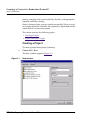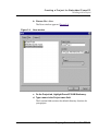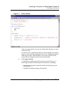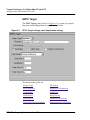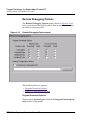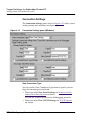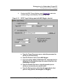
1
CodeWarrior ®
Targeting Embedded
PowerPC
Because of last-minute changes to CodeWarrior,
some of the information in this manual may be
inaccurate. Please read the Release Notes on the
CodeWarrior CD for the most recent information.
Revised: 991129-CIB
Metrowerks CodeWarrior copyright ©1993–1999 by Metrowerks Inc. and its licensors.
All rights reserved.
Documentation stored on the compact disk(s) may be printed by licensee for personal
use. Except for the foregoing, no part of this documentation may be reproduced or transmitted in any form by any means, electronic or mechanical, including photocopying,
recording, or any information storage and retrieval system, without permission in
writing from Metrowerks Inc.
Metrowerks, the Metrowerks logo, CodeWarrior, and Software at Work are registered
trademarks of Metrowerks Inc. PowerPlant and PowerPlant Constructor are trademarks
of Metrowerks Inc.
All other trademarks and registered trademarks are the property of their respective
owners.
ALL SOFTWARE AND DOCUMENTATION ON THE COMPACT DISK(S) ARE
SUBJECT TO THE LICENSE AGREEMENT IN THE CD BOOKLET.
How to Contact Metrowerks:
U.S.A. and international Metrowerks Corporation
9801 Metric Blvd., Suite 100
Austin, TX 78758
U.S.A.
Canada Metrowerks Inc.
1500 du College, Suite 300
Ville St-Laurent, QC
Canada H4L 5G6
Ordering Voice: (800) 377–5416
Fax: (512) 873–4901
World Wide Web http://www.metrowerks.com
Registration information [email protected]
Technical support [email protected]
Sales, marketing, & licensing [email protected]
CompuServe Goto: Metrowerks
Table of Contents
1 Introduction
11
Read the Release Notes! . . . . .
Solaris: Host-Specific Information .
About This Book . . . . . . . .
Where to Go from Here . . . . .
Technical Support. . . . . . . .
Metrowerks Year 2000 Compliance
.
.
.
.
.
.
.
.
.
.
.
.
.
.
.
.
.
.
.
.
.
.
.
.
.
.
.
.
.
.
.
.
.
.
.
.
.
.
.
.
.
.
.
.
.
.
.
.
.
.
.
.
.
.
.
.
.
.
.
.
.
.
.
.
.
.
.
.
.
.
.
.
.
.
.
.
.
.
2 Getting Started
11
12
12
15
18
19
21
System Requirements . . . . . . . . . . . . . .
Installing CodeWarrior for Embedded PowerPC . .
CodeWarrior Compiler Architecture. . . . . . . .
Development Tools for Embedded PowerPC . . . .
CodeWarrior IDE. . . . . . . . . . . . . . .
CodeWarrior Compiler for Embedded PowerPC .
CodeWarrior Assembler for Embedded PowerPC.
CodeWarrior Linker for Embedded PowerPC . .
CodeWarrior Debugger for Embedded PowerPC .
MetroTRK . . . . . . . . . . . . . . . . . .
Metrowerks Standard Libraries . . . . . . . .
The Development Process with CodeWarrior . . . .
Makefiles . . . . . . . . . . . . . . . . . .
Editing Code . . . . . . . . . . . . . . . .
Compiling. . . . . . . . . . . . . . . . . .
Linking . . . . . . . . . . . . . . . . . . .
Debugging . . . . . . . . . . . . . . . . .
Viewing Preprocessor Output . . . . . . . . .
.
.
.
.
.
.
.
.
.
.
.
.
.
.
.
.
.
.
.
.
.
.
.
.
.
.
.
.
.
.
.
.
.
.
.
.
.
.
.
.
.
.
.
.
.
.
.
.
.
.
.
.
.
.
.
.
.
.
.
.
.
.
.
.
.
.
.
.
.
.
.
.
.
.
.
.
.
.
.
.
.
.
.
.
.
.
.
.
.
.
.
.
.
.
.
.
.
.
.
.
.
.
.
.
.
.
.
.
.
.
.
.
.
.
.
3 Creating a Project for Embedded PowerPC
Types of Projects . . . . .
Project Stationery . . . . .
Creating a Project . . .
Project Stationery Targets
Working with a Project . .
.
.
.
.
.
.
.
.
.
.
.
.
.
.
.
21
24
25
25
26
26
27
27
28
28
29
29
30
31
31
31
32
32
33
.
.
.
.
.
.
.
.
.
.
.
.
.
.
.
.
.
.
.
.
.
.
.
.
.
.
.
.
.
.
.
.
.
.
.
.
.
.
.
.
33
33
34
37
38
Targeting Embedded PowerPC PPC–3
4 Target Settings for Embedded PowerPC
Target Settings Overview . . . . . .
Settings Panels to Optimize Code . . .
Settings Panels for Embedded PowerPC
Target Settings . . . . . . . . . .
EPPC Target . . . . . . . . . . .
EPPC Assembler . . . . . . . . .
Global Optimizations . . . . . . .
EPPC Processor . . . . . . . . .
EPPC Disassembler . . . . . . . .
EPPC Linker . . . . . . . . . . .
EPPC Target Settings . . . . . . .
Remote Debugging Options . . . .
EPPC Exceptions . . . . . . . . .
Connection Settings . . . . . . .
63
.
.
.
.
.
.
.
.
.
.
.
.
.
.
.
.
.
.
.
.
.
.
.
.
.
.
.
.
.
.
.
.
.
.
.
.
.
.
.
.
.
.
.
.
.
.
.
.
.
.
.
.
.
.
.
.
.
.
.
.
.
.
.
.
.
.
.
.
.
.
.
.
.
.
.
.
.
.
.
.
.
.
.
.
.
.
.
.
.
.
.
.
.
.
.
.
.
.
.
.
.
.
.
.
.
.
.
.
.
.
.
.
.
.
.
.
.
.
.
.
.
.
.
.
.
.
.
.
.
.
.
.
.
.
.
.
.
.
.
.
5 Debugging for Embedded PowerPC
Supported Debugging Methods . . . . . . . . . . . .
Setting Up for Remote Debugging . . . . . . . . . . .
Configuring Your Embedded PowerPC Board . . . . .
Connecting with a Debug Monitor . . . . . . . . . .
Connecting with CodeTAP . . . . . . . . . . . . .
Connecting with PowerTAP . . . . . . . . . . . . .
Connecting with Wiggler, Hummingbird, or Raven BDM
Connecting with Raven COP. . . . . . . . . . . . .
Connecting with Abatron BDI2000 . . . . . . . . . .
Special Debugger Features for Embedded PowerPC . . . .
Displaying Registers . . . . . . . . . . . . . . . .
EPPC Menu . . . . . . . . . . . . . . . . . . . .
AMC Data and Instruction Cache Windows . . . . . .
Register Details Window . . . . . . . . . . . . . . .
Using MetroTRK . . . . . . . . . . . . . . . . . . .
MetroTRK Overview . . . . . . . . . . . . . . . .
MetroTRK Baud Rates . . . . . . . . . . . . . . .
MetroTRK Memory Configuration . . . . . . . . . .
PPC–4 Targeting Embedded PowerPC
. 63
. 65
. 66
. 67
. 70
. 75
. 78
. 79
. 87
. 90
. 101
. 114
. 116
. 118
123
.
.
.
.
.
.
.
.
.
.
.
.
.
.
.
.
.
.
. 123
. 126
. 127
. 127
. 132
. 136
. 140
. 142
. 143
. 147
. 147
. 150
. 152
. 155
. 157
. 157
. 158
. 158
Using MetroTRK for Debugging. . . . . . . .
Debugging ELF Files . . . . . . . . . . . . . .
Customizing the Default XML Project File . . .
Debugging an ELF File . . . . . . . . . . . .
ELF File Debugging: Additional Considerations .
.
.
.
.
.
.
.
.
.
.
.
.
.
.
.
.
.
.
.
.
.
.
.
.
.
6 C and C++ for Embedded PowerPC
162
162
163
164
165
167
Integer Formats . . . . . . . . . . . . . .
Embedded PowerPC Integer Formats . . .
Embedded PowerPC Floating-Point Formats
AltiVec Vector Data Formats . . . . . . .
Data Addressing. . . . . . . . . . . . . .
Calling Conventions . . . . . . . . . . . .
Register Variables . . . . . . . . . . . . .
Register Coloring Optimization . . . . . . .
Generating Code for Specific Processors . . .
Pragmas . . . . . . . . . . . . . . . . .
force_active. . . . . . . . . . . . . . .
function_align . . . . . . . . . . . . .
incompatible_return_small_structs . . . .
incompatible_sfpe_double_params . . . .
interrupt . . . . . . . . . . . . . . . .
pack . . . . . . . . . . . . . . . . . .
pooled_data . . . . . . . . . . . . . .
section . . . . . . . . . . . . . . . . .
Linker Issues for Embedded PowerPC . . . .
Linker Generated Symbols . . . . . . . .
Deadstripping Unused Code and Data . . .
Link Order . . . . . . . . . . . . . . .
Linker Command Files . . . . . . . . . .
__attribute__ ((aligned(?))) . . . . . . . . .
Variable Declaration Examples . . . . . .
Struct Definition Examples . . . . . . . .
Typedef Declaration Examples . . . . . .
Struct Member Examples . . . . . . . . .
.
.
.
.
.
.
.
.
.
.
.
.
.
.
.
.
.
.
.
.
.
.
.
.
.
.
.
.
.
.
.
.
.
.
.
.
.
.
.
.
.
.
.
.
.
.
.
.
.
.
.
.
.
.
.
.
.
.
.
.
.
.
.
.
.
.
.
.
.
.
.
.
.
.
.
.
.
.
.
.
.
.
.
.
.
.
.
.
.
.
.
.
.
.
.
.
.
.
.
.
.
.
.
.
.
.
.
.
.
.
.
.
.
.
.
.
.
.
.
.
.
.
.
.
.
.
.
.
.
.
.
.
.
.
.
.
.
.
.
.
.
.
.
.
.
.
.
.
.
.
.
.
.
.
.
.
.
.
.
.
.
.
.
.
.
.
.
.
.
.
.
.
.
.
.
.
.
.
.
.
.
.
.
.
.
.
.
.
.
.
.
.
.
.
.
.
168
169
170
170
171
174
174
175
177
177
179
179
180
180
180
181
182
183
189
190
191
192
192
203
203
204
204
205
Targeting Embedded PowerPC PPC–5
7 Libraries and Runtime Code for Embedded PowerPC
MSL for Embedded PowerPC . . . . . . . . . . . . .
Using MSL for Embedded PowerPC . . . . . . . . .
Using Console I/O for Embedded PowerPC . . . . . .
Allocating Memory and Heaps for Embedded PowerPC.
Runtime Libraries for Embedded PowerPC . . . . . . .
Board Initialization Code . . . . . . . . . . . . . . .
207
.
.
.
.
.
.
8 Inline Assembler for Embedded PowerPC
Working With Assembly . . . . . . . . . . . . . . . .
Assembler Syntax for Embedded PowerPC . . . . . .
Special Embedded PowerPC Instructions . . . . . . .
Support for AltiVec Instructions . . . . . . . . . . .
Creating Labels for Embedded PowerPC Assembly . . .
Using Comments in Embedded PowerPC Assembly . .
Using the Preprocessor in Embedded PowerPC Assembly
Using Local Variables and Arguments. . . . . . . . .
Creating a Stack Frame in Embedded PowerPC Assembly
Specifying Operands in Embedded PowerPC Assembly .
Assembler Directives . . . . . . . . . . . . . . . . .
entry . . . . . . . . . . . . . . . . . . . . . . .
fralloc. . . . . . . . . . . . . . . . . . . . . . .
frfree . . . . . . . . . . . . . . . . . . . . . . .
machine. . . . . . . . . . . . . . . . . . . . . .
nofralloc . . . . . . . . . . . . . . . . . . . . .
opword . . . . . . . . . . . . . . . . . . . . . .
Intrinsic Functions . . . . . . . . . . . . . . . . . .
Low-Level Processor Synchronization. . . . . . . . .
Floating-Point Functions . . . . . . . . . . . . . .
Byte-Reversing Functions . . . . . . . . . . . . . .
Setting the Floating-Point Environment . . . . . . . .
Manipulating the Contents of a Variable or Register. . .
Data Cache Manipulation . . . . . . . . . . . . . .
Math Functions . . . . . . . . . . . . . . . . . .
Buffer Manipulation . . . . . . . . . . . . . . . .
PPC–6 Targeting Embedded PowerPC
. 207
. 208
. 209
. 212
. 212
. 214
215
.
.
.
.
.
.
.
.
.
.
.
.
.
.
.
.
.
.
.
.
.
.
.
.
.
.
. 216
. 216
. 220
. 220
. 221
. 221
. 222
. 222
. 223
. 224
. 230
. 230
. 231
. 231
. 232
. 234
. 234
. 234
. 235
. 236
. 236
. 237
. 237
. 238
. 239
. 240
AltiVec Intrinsics Support . . . . . . . . . . . . . . . 240
9 Troubleshooting for Embedded PowerPC
243
No Communications with Target Board. . . . . . . .
Downloading Code Fails or Crash When Code Runs . .
Debugger Window Does Not Appear. . . . . . . . .
Common Error Warnings for CodeTAP and PowerTAP .
Targeting BDM Devices FAQ . . . . . . . . . . . .
.
.
.
.
.
.
.
.
.
.
.
.
.
.
.
10 Using a CodeTAP Debugging Device
249
CodeTAP Highlights . . . . . . .
CodeTAP Technical Support. . . .
CodeTAP Requirements . . . . .
Target Settings for CodeTAP . . .
Setting Up the CodeTAP Emulator .
Updating the CodeTAP Firmware .
Debugging Using CodeTAP . . . .
Resetting the Processor . . . . . .
.
.
.
.
.
.
.
.
.
.
.
.
.
.
.
.
.
.
.
.
.
.
.
.
.
.
.
.
.
.
.
.
.
.
.
.
.
.
.
.
.
.
.
.
.
.
.
.
.
.
.
.
.
.
.
.
.
.
.
.
.
.
.
.
.
.
.
.
.
.
.
.
.
.
.
.
.
.
.
.
.
.
.
.
.
.
.
.
.
.
.
.
.
.
.
.
11 Using the PowerTAP 6xx/7xx Debugging Device
250
251
252
252
254
255
255
255
257
PowerTAP Highlights . . . . . . . . . . . . . . . . .
PowerTAP Technical Support . . . . . . . . . . . . . .
PowerTAP Requirements . . . . . . . . . . . . . . . .
Target Settings for PowerTAP . . . . . . . . . . . . . .
Setting Up the PowerTAP Emulator . . . . . . . . . . .
Updating the PowerTAP Firmware. . . . . . . . . . . .
Resetting the Processor . . . . . . . . . . . . . . . . .
Operational Notes . . . . . . . . . . . . . . . . . . .
Recoverable Interrupts . . . . . . . . . . . . . . . .
Interrupts and the Machine Status Save/Restore Registers
.
.
.
.
.
.
.
.
.
.
A Flash Programmer
What You See . . .
Console . . . .
Status and Errors
Help. . . . . .
243
244
245
245
246
258
259
260
260
262
263
263
264
264
265
267
.
.
.
.
.
.
.
.
.
.
.
.
.
.
.
.
.
.
.
.
.
.
.
.
.
.
.
.
.
.
.
.
.
.
.
.
.
.
.
.
.
.
.
.
.
.
.
.
.
.
.
.
.
.
.
.
.
.
.
.
.
.
.
.
.
.
.
.
.
.
.
.
.
.
.
.
267
268
268
269
Targeting Embedded PowerPC PPC–7
Preferences . . . . . . . . . . . . . .
Using the Flash Programmer . . . . . . . .
Initialize the Programmer . . . . . . . .
Specify a Flash Image . . . . . . . . . .
Send the Flash Image . . . . . . . . . .
Command File Syntax . . . . . . . . . . .
Write Register Commands . . . . . . . .
Read, Write and Save Memory Commands
Loop Commands . . . . . . . . . . . .
Action Commands . . . . . . . . . . .
Wait and Abort Commands . . . . . . .
Print Commands . . . . . . . . . . . .
Miscellaneous Commands . . . . . . . .
.
.
.
.
.
.
.
.
.
.
.
.
.
.
.
.
.
.
.
.
.
.
.
.
.
.
.
.
.
.
.
.
.
.
.
.
.
.
.
.
.
.
.
.
.
.
.
.
.
.
.
.
.
.
.
.
.
.
.
.
.
.
.
.
.
.
.
.
.
.
.
.
.
.
.
.
.
.
.
.
.
.
.
.
.
.
.
.
.
.
.
B Debug Initialization Files
Using Debug Initialization Files . . . . . .
Creating Stand-alone Code . . . . . . .
Initializing Memory . . . . . . . . . .
Enabling Debug Support . . . . . . . .
Creating a Debug Initialization File . . . .
Disabling the Software Watchdog Timer . .
Using Emulator Operational Settings . . .
Proper Use of Debug Initialization Files . . .
Debug Initialization File Commands . . . .
Debug Initialization File Command Syntax
CodeTAP Commands . . . . . . . . . .
PowerTAP Commands . . . . . . . . .
Macraigor Wiggler Commands. . . . . .
Abatron BDI2000 Commands . . . . . .
AMCMemReadDelayCycles . . . . . . .
AMCMemWriteDelayCycles . . . . . . .
AMCMemWriteVerify . . . . . . . . .
AMCRegWriteVerify . . . . . . . . . .
AMCTargetInterfaceClockFreq . . . . . .
AMCTargetSerializeInstExec . . . . . . .
PPC–8 Targeting Embedded PowerPC
. 270
. 273
. 274
. 274
. 274
. 275
. 275
. 277
. 282
. 284
. 284
. 285
. 286
289
.
.
.
.
.
.
.
.
.
.
.
.
.
.
.
.
.
.
.
.
.
.
.
.
.
.
.
.
.
.
.
.
.
.
.
.
.
.
.
.
.
.
.
.
.
.
.
.
.
.
.
.
.
.
.
.
.
.
.
.
.
.
.
.
.
.
.
.
.
.
.
.
.
.
.
.
.
.
.
.
.
.
.
.
.
.
.
.
.
.
.
.
.
.
.
.
.
.
.
.
.
.
.
.
.
.
.
.
.
.
.
.
.
.
.
.
.
.
.
.
.
.
.
.
.
.
.
.
.
.
.
.
.
.
.
.
.
.
.
.
. 289
. 290
. 290
. 291
. 291
. 293
. 293
. 294
. 294
. 296
. 296
. 297
. 298
. 299
. 299
. 300
. 300
. 300
. 301
. 301
AMCTargetShowInstCycles.
initregs . . . . . . . . .
polltime . . . . . . . . .
setMMRBaseAddr . . . . .
sleep. . . . . . . . . . .
writedcr . . . . . . . . .
writemem.b . . . . . . .
writemem.l . . . . . . . .
writemem.w . . . . . . .
writemmr . . . . . . . .
writereg . . . . . . . . .
writespr . . . . . . . . .
writeupma . . . . . . . .
writeupmb . . . . . . . .
.
.
.
.
.
.
.
.
.
.
.
.
.
.
.
.
.
.
.
.
.
.
.
.
.
.
.
.
.
.
.
.
.
.
.
.
.
.
.
.
.
.
.
.
.
.
.
.
.
.
.
.
.
.
.
.
.
.
.
.
.
.
.
.
.
.
.
.
.
.
.
.
.
.
.
.
.
.
.
.
.
.
.
.
.
.
.
.
.
.
.
.
.
.
.
.
.
.
.
.
.
.
.
.
.
.
.
.
.
.
.
.
.
.
.
.
.
.
.
.
.
.
.
.
.
.
.
.
.
.
.
.
.
.
.
.
.
.
.
.
.
.
.
.
.
.
.
.
.
.
.
.
.
.
.
.
.
.
.
.
.
.
.
.
.
.
.
.
.
.
.
.
.
.
.
.
.
.
.
.
.
.
.
.
.
.
.
.
.
.
.
.
.
.
.
.
C JTAG Configuration Files
301
302
302
303
303
304
304
304
305
305
306
306
307
307
309
Generating JTAG Configuration Files . . . . . . . . . . . . 309
D Memory Configuration Files
313
Command Syntax . . . . . . . . . .
Memory Configuration File Commands
reservedchar . . . . . . . . . . .
range . . . . . . . . . . . . . .
reserved . . . . . . . . . . . . .
.
.
.
.
.
.
.
.
.
.
.
.
.
.
.
.
.
.
.
.
.
.
.
.
.
.
.
.
.
.
.
.
.
.
.
.
.
.
.
.
.
.
.
.
.
.
.
.
.
.
E Tested Jumper and Dipswitch Settings
Cogent CMA102 with CMA 278 Daughtercard.
IBM 403 EVB . . . . . . . . . . . . . . .
Motorola MPC 505/509 EVB . . . . . . . .
Motorola 555 ETAS . . . . . . . . . . . .
Motorola Excimer 603e . . . . . . . . . . .
Motorola Yellowknife X4 603/750 . . . . . .
Motorola MPC 8xx ADS . . . . . . . . . .
Motorola MPC 8xx MBX . . . . . . . . . .
Motorola MPC 8xx FADS . . . . . . . . . .
Embedded Planet RPX Lite 8xx . . . . . . .
313
314
314
314
315
317
.
.
.
.
.
.
.
.
.
.
.
.
.
.
.
.
.
.
.
.
.
.
.
.
.
.
.
.
.
.
.
.
.
.
.
.
.
.
.
.
.
.
.
.
.
.
.
.
.
.
.
.
.
.
.
.
.
.
.
.
.
.
.
.
.
.
.
.
.
.
318
319
319
320
321
321
322
323
324
325
Targeting Embedded PowerPC PPC–9
Motorola Maximer 7400 . . . . .
Motorola Sandpoint 8240 . . . .
Motorola MPC 8260 VADS . . . .
Phytec miniMODUL-PPC 505/509
F Command-Line Tool Options
.
.
.
.
.
.
.
.
.
.
.
.
.
.
.
.
.
.
.
.
.
.
.
.
.
.
.
.
.
.
.
.
.
.
.
.
.
.
.
.
.
.
.
.
.
.
.
.
. 326
. 326
. 327
. 328
329
Embedded PowerPC Project Options . . . . . . . . . . . . 329
Embedded PowerPC Options . . . . . . . . . . . . . . . 331
Embedded PowerPC Disassembler Options . . . . . . . . . 333
Index
PPC–10 Targeting Embedded PowerPC
337
1
Introduction
This manual shows you how to install and use CodeWarrior to develop software for Embedded PowerPC systems.
This chapter provides an introduction to the manual and CodeWarrior for Embedded PowerPC, it contains the following sections:
• Read the Release Notes!
• Solaris: Host-Specific Information
• About This Book
• Where to Go from Here
• Metrowerks Year 2000 Compliance
Read the Release Notes!
Before you use CodeWarrior or a particular tool, you should read
the release notes. They contain important last-minute information
about new features, and technical issues or incompatibilities that
may not be included in the documentation.
The release notes directory is always included as part of a standard
CodeWarrior installation. You can also find them on the CodeWarrior for Embedded PowerPC CD, in the Release Notes folder.
Targeting Embedded PowerPC PPC–11
I ntro d u c t i o n
Solaris: Host-Specific Information
Solaris: Host-Specific Information
The Solaris hosted tools are functionally equivalent to the Windows
hosted tools, with the following minor differences:
• No Wiggler or Hummingbird support—because the operation of the Macraigor Systems’ Wiggler depends on the parallel port on PC compatibles.
• Connection Settings panel changes—The Port option in the
Connection Settings panel uses Unix communication port
conventions.
• Different baud rates apply for MetroTRK when running Solaris 5.1. See “MetroTRK Baud Rates” on page 158 for a table
of baud rates.
• The flash utility, PPCComUtil, has not been ported to Solaris;
therefore flashing that does not use project stationeries that
include a Burn ROM target must be done on a Windows
computer.
When using Solaris, MetroTRK projects that use PowerTAP
(from Applied Microsystems Corporation, Inc.) can selfflash. However, MetroTRK projects that use Wiggler do not
self-flash for Solaris. Because PPCComUtil is not available for
Solaris, you must use a Windows computer to flash MetroTRK projects that use Wiggler.
• All file path names are shown in DOS format. Solaris path
names are identical to the DOS path, except a forward slash
should replace the back slash.
About This Book
CodeWarrior is a multi-host, multi-language, multi-target development environment. Most features of CodeWarrior apply no matter
what platform target you are programming for. However, each target has its own unique features. This manual describes those unique
features to programming for Embedded PowerPC.
General features of CodeWarrior are described in other manuals.
For a complete understanding of CodeWarrior, you must refer to
PPC–12 Targeting Embedded PowerPC
Int ro d u ct io n
About This Book
both the generic documentation and the documentation that is specific to your particular platform target, such as this manual.
The documentation is organized so that various chapters in this
manual are extensions of particular generic manuals, as shown in
Table 1.1. For a complete discussion of a particular subject, you may
need to look in both the generic manual and the corresponding
chapter in this Targeting manual.
Table 1.1
CodeWarrior documentation architecture
This chapter...
Extends...
Target Settings for Embedded PowerPC
IDE User Guide
Debugging for Embedded PowerPC
IDE User Guide
C and C++ for Embedded PowerPC
C Compilers Reference
Libraries and Runtime Code for Embed- MSL C Reference
ded PowerPC
MSL C++ Reference
Inline Assembler for Embedded PowerPC
Assembler Guide
For example, to completely understand the C/C++ compiler, you
need to know the information in the C Compilers Reference (which
covers the C/C++ front-end compiler) and the information in the C
and C++ for Embedded PowerPC chapter in this manual, which
covers the back-end compiler that generates target-specific code.
Table 1.2 lists every chapter in this manual, and describes the information contained in each.
Table 1.2
Contents of chapters
Chapter
Description
Introduction
This chapter.
Getting Started
Installation and setup instructions
and an overview of CodeWarrior.
Targeting Embedded PowerPC PPC–13
I ntro d u c t i o n
About This Book
Chapter
Description
Creating a Project for Embedded PowerPC
The kinds of projects you can build
and how to build them.
Target Settings for Embedded PowerPC
How to control the compiler, linker,
and debugger for this platform target.
Debugging for Embedded
PowerPC
Includes details on debugger setup
for embedded systems.
C and C++ for Embedded
PowerPC
Details of the back-end compiler for
Embedded PowerPC development.
Libraries and Runtime
Code for Embedded PowerPC
Libraries provided with CodeWarrior for this platform target.
Inline Assembler for Embedded PowerPC
Describes support for inline assembly language programming built
into the CodeWarrior compilers.
Troubleshooting for Embedded PowerPC
Troubleshooting information specific to this platform target.
Using a CodeTAP Debugging Device
Information relevant to using a CodeTAP debugging device with
CodeWarrior.
Using the PowerTAP 6xx/
7xx Debugging Device
Information relevant to using a
PowerTAP debugging device with
CodeWarrior.
Flash Programmer
How to use the Embedded PowerPC utility to burn flash images to
your embedded PowerPC board.
Debug Initialization Files
Discusses debug initialization files
and the commands that you can use
in the files, including command syntax.
JTAG Configuration Files
Discusses JTAG files and how to
clone them.
PPC–14 Targeting Embedded PowerPC
Int ro d u ct io n
Where to Go from Here
Chapter
Description
Memory Configuration
Files
Discusses the memory configuration
file commands, including command syntax.
Tested Jumper and
Dipswitch Settings
Provides tested jumper and
dipswitch settings for a number of
supported target boards.
Command-Line Tool Options
Describes the command-line tool
options that are specific to
CodeWarrior for Embedded PowerPC.
Where to Go from Here
All the manuals mentioned here are available as part of the
CodeWarrior documentation included with your product.
If you are new to CodeWarrior:
• Look for the CodeWarrior core tutorials in the CodeWarrior Documentation directory.
• Read “Development Tools for Embedded PowerPC” on page
25.
For everyone:
• For general information about the CodeWarrior IDE and debugger, see the IDE User Guide.
• For information specific to the C/C++ front-end compiler,
see the C Compilers Reference.
• For information on Metrowerks’ standard C/C++ libraries,
see the MSL C Reference and the MSL C++ Reference.
• For general information on MetroTRK and how to customize
MetroTRK to work with additional target boards, see MetroTRK Reference.
Targeting Embedded PowerPC PPC–15
I ntro d u c t i o n
Where to Go from Here
For general information on Embedded PowerPC programming:
To learn more about the Embedded PowerPC Application Binary
Interface (PowerPC EABI), refer to the following documents:
• System V Application Binary Interface, Third Edition, published
by UNIX System Laboratories, 1994 (ISBN 0-13-100439-5).
• System V Application Binary Interface, PowerPC Processor Supplement, published by Sun Microsystems and IBM (1995) and
available on the World Wide Web at the following address:
http://www.mot.com/SPS/ADC/pps/download/8XX/
SVR4abippc.pdf
NOTE: The pages of the preceding PDF file are in reverse order.
• PowerPC Embedded Binary Interface, 32-Bit Implementation.,
published by Motorola, Inc., and available on the World
Wide Web at the following address:
http://www.mot.com/SPS/ADC/pps/download/8XX/
ppceabi.pdf
The PowerPC EABI specifies data structure alignment, calling conventions, and other information about how high-level languages
can be implemented on a Embedded PowerPC processor. Code generated by CodeWarrior for Embedded PowerPC conforms to the
PowerPC EABI.
The PowerPC EABI also specifies the object and symbol file format.
It specifies ELF (Executable and Linker Format) as the output file
format and DWARF (Debug With Arbitrary Record Formats) as the
symbol file format. For more information about those file formats,
you should read the following documents:
• Executable and Linker Format, Version 1.1, published by UNIX
System Laboratories.
• DWARF Debugging Information Format, Revision: Version 1.1.0,
published by UNIX International, Programming Languages
SIG, October 6, 1992, and available on the World Wide Web
at the following address:
http://www.esofta.com/pdfs/dwarf.v1.1.0.pdf
PPC–16 Targeting Embedded PowerPC
Int ro d u ct io n
Where to Go from Here
• DWARF Debugging Information Format, Revision: Version 2.0.0,
Industry Review Draft, published by UNIX International,
Programming Languages SIG, July 27, 1993.
For information on Applied Microsytems Corporation’s
CodeTAP and PowerTAP:
• Emulator Installation Guide, CodeTAP for the Motorola
MPC8XX, published by AMC (Applied Microsystems Corporation).
• Emulator Installation Guide, PowerTAP for PowerPC Processors,
published by AMC.
For information on AltiVecTM:
To learn more about AltiVec, see:
• AltiVec Technology Programming Interface Manual, published
by Motorola, Inc., and available on the World Wide Web at
the following address:
http://www.mot.com/SPS/PowerPC/teksupport/
teklibrary/manuals/altivecpim.pdf
• AltiVec Technology Programming Environments Manual, published by Motorola, Inc., and available on the World Wide
Web at the following address:
http://www.mot.com/SPS/PowerPC/teksupport/
teklibrary/manuals/altivec_pem.pdf
• PowerPC Advance Information MPC7400 RISC Microprocessor Technical Summary, published by Motorola, Inc., and
available on the World Wide Web at the following address:
http://www.mot.com/SPS/PowerPC/teksupport/
teklibrary/techsum/7400ts.pdf
Targeting Embedded PowerPC PPC–17
I ntro d u c t i o n
Technical Support
Technical Support
If you are having problems installing or using a Metrowerks product, contact Metrowerks Technical Support.
There are several ways you can contact Technical Support, Table 1.3
lists your technical support options.
Table 1.3
Technical Support options
E-mail
[email protected]
Telephone
(512) 873-4700
Newsgroup
comp.sys.mac.programmer.codewarrior
World Wide Web
http://www.metrowerks.com/support/embedded
Compuserve
Go: Metrowerks
To assist Technical Support in answering your question, please use
{CodeWarrior Directory}\Release_Notes\email_Tech_Question_Form.txt
when submitting a support question.
Contacting the Documentation team
At Metrowerks, our goal is to deliver the highest quality software
and documentation. To achieve this goal, we need your feedback.
Please send any errors, omissions, suggestions, or general comments about CodeWarrior documentation to:
[email protected]
PPC–18 Targeting Embedded PowerPC
Int ro d u ct io n
Metrowerks Year 2000 Compliance
Metrowerks Year 2000 Compliance
The Products provided by Metrowerks under the License agreement process dates only to the extent that the Products use date data
provided by the host or target operating system for date representations used in internal processes, such as file modifications. Any Year
2000 Compliance issues resulting from the operation of the Products
are therefore necessarily subject to the Year 2000 Compliance of the
relevant host or target operating system.
Metrowerks directs you to the relevant statements of Microsoft Corporation, Sun Microsystems, Inc., Apple Computer, Inc., and other
host or target operating systems relating to the Year 2000 Compliance of their operating systems. Except as expressly described
above, the Products, in themselves, do not process date data and
therefore do not implicate Year 2000 Compliance issues.
For additional information, visit:
http://www.metrowerks.com/about/y2k.html
Targeting Embedded PowerPC PPC–19
I ntro d u c t i o n
Metrowerks Year 2000 Compliance
PPC–20 Targeting Embedded PowerPC
2
Getting Started
This chapter gives you the information you need to install
CodeWarrior. For new CodeWarrior users, this chapter provides a
brief overview of the CodeWarrior development environment.
This chapter includes the following topics:
• System Requirements
• Installing CodeWarrior for Embedded PowerPC
• CodeWarrior Compiler Architecture
• Development Tools for Embedded PowerPC
• The Development Process with CodeWarrior
System Requirements
Currently, the host platforms available for programming Embedded
PowerPC systems with CodeWarrior are Windows 32-bit operating
systems and Solaris.
Windows Requirements
• A personal computer with a Pentium or higher processor,
with a CD-ROM drive to install CodeWarrior software, documentation, and examples.
• Microsoft Windows 95, Windows 98, or Windows NT 4.0 operating system.
• A minimum of 32 MB of RAM.
Solaris
• A Sparc-based machine with the following system software
and hardware:
– Solaris 2.5.1 or later
– Motif 1.2 or later (CDE recommended)
Targeting Embedded PowerPC PPC–21
G e t t i n g St a r te d
System Requirements
– X11-R5 display server
• A minimum of 64 MB of RAM.
• 80 MB free hard disk space.
• A CD-ROM drive to install CodeWarrior software, documentation, and examples.
Target board requirements
A target board from one of the following manufacturers is recommended:
Cogent Computer Systems, Inc.
– Cogent CMA102 with CMA 278 Daughtercard
IBM
• IBM 403 EVB
Motorola
• Motorola MPC 505/509 EVB
• Motorola 555 ETAS
• Motorola Excimer 603e
• Motorola Yellowknife X4 603/750
• Motorola MPC 8xx ADS
• Motorola MPC 8xx MBX
• Motorola MPC 8xx FADS
• Motorola Maximer 7400
• Motorola Sandpoint 8240
• Motorola MPC 8260 VADS
Embedded Planet
• Embedded Planet RPX Lite 8xx
Phytec
• Phytec miniMODUL-PPC 505/509
PPC–22 Targeting Embedded PowerPC
Get t ing St ar t ed
System Requirements
Additional Requirements
• If you are debugging with MetroTRK, you need a serial cable
to connect your host system with the embedded target. (For
more information, see “MetroTRK” on page 28.)
• If you are debugging using the Macraigor Wiggler, a parallel
cable should be included with your package.
• If you are debugging using an AMC (Applied Microsystems
Corporation) CodeTAP or PowerTAP debugging device, you
need an Ethernet cable.
NOTE: If you are using a CodeTAP or PowerTAP device, see
“Using a CodeTAP Debugging Device” on page 249 or “Using the
PowerTAP 6xx/7xx Debugging Device” on page 257.
Some of the support code included with CodeWarrior is specific to
the kind of board being targeted. These portions of code are implemented for certain reference hardware configurations. If you are not
using a supported reference configuration, this code may not work
correctly on your platform target. For this reason, this product includes all such code in source form so that you can customize the
code to work with your hardware.
WARNING! If you are not using a supported reference configuration, the support code included with CodeWarrior may not work
correctly on your platform target.
The following support code makes board-specific assumptions:
• MetroTRK
For more information, see “Using MetroTRK” on page 157.
• Debug initialization files
For more information, see “Debug Initialization Files” on
page 289.
• Console I/O under standard C and C++ libraries
Targeting Embedded PowerPC PPC–23
G e t t i n g St a r te d
Installing CodeWarrior for Embedded PowerPC
For more information, see “Using Console I/O for Embedded PowerPC” on page 209.
• Stand-alone application startup code
For more information, see “Board Initialization Code” on
page 214.
Contact a hardware vendor for more information about using a
PowerPC processor in your embedded circuit design.
Installing CodeWarrior for Embedded PowerPC
Your first step toward developing software for your platform target
is to install the CodeWarrior tools. (If you have already installed the
software, you can skip ahead to CodeWarrior Compiler Architecture.) The tools include a variety of components such as the IDE, debugger, plug-in compilers and linkers, standard libraries, runtime
libraries and headers, and all necessary documentation.
The CodeWarrior Installer automatically copies all necessary components to the correct locations. It is strongly recommended that you
use the CodeWarrior Installer to ensure that you have all the required files. If you have questions regarding installer options, read
the installer on-screen instructions.
To start the Installer:
1.
Double-click the drive on the desktop that holds the CodeWarrior
CD.
When you do, a dialog box appears with a button titled Launch
CodeWarrior Setup.
2.
Press the Launch CodeWarrior Setup button.
If for some reason you do not see this dialog, double-click the
setup.exe file located at the root level of the CD.
PPC–24 Targeting Embedded PowerPC
Get t ing St ar t ed
CodeWarrior Compiler Architecture
CodeWarrior Compiler Architecture
A proprietary multi-language, multi-target compiler architecture is
at the heart of CodeWarrior. Front-end language compilers generate
a memory-resident, unambiguous, language-independent intermediate representation (IR) of syntactically correct source code. Backend compilers generate code from the IR for specific platform targets. The CodeWarrior IDE manages the whole process.
As a result of this architecture, the same front-end compiler is used
in support of multiple back-end build targets. In some cases, the
same back-end compiler can generate code from a variety of languages.
All compilers are built as plug-in modules. The interface between
the IDE and compilers and linkers is public, so third parties can
create compilers that work with CodeWarrior.
Once the compiler generates object code, the plug-in linker generates the final executable. Some build targets have multiple linkers
available to support different object code formats.
Development Tools for Embedded PowerPC
Programming for Embedded PowerPC is much like programming
for any other target in CodeWarrior. If you have never used
CodeWarrior before, the tools you will need to become familiar with
are:
• CodeWarrior IDE
• CodeWarrior Compiler for Embedded PowerPC
• CodeWarrior Assembler for Embedded PowerPC
• CodeWarrior Linker for Embedded PowerPC
• CodeWarrior Debugger for Embedded PowerPC
• MetroTRK
• Metrowerks Standard Libraries
Targeting Embedded PowerPC PPC–25
G e t t i n g St a r te d
Development Tools for Embedded PowerPC
If you are an experienced CodeWarrior user, this is the same IDE
and debugger that you have been using all along. You will, however, need to become familiar with the Embedded PowerPC runtime software environment.
CodeWarrior IDE
The CodeWarrior IDE is the application that allows you to write
your executable. It controls the project manager, the source code editor, the class browser, the compilers and linkers, and the debugger.
The CodeWarrior project manager may be new to those more familiar with command-line development tools. All files related to your
project are organized in the project manager. This allows you to see
your project at a glance, and eases the organization of and navigation between your source code files.
For more information about how the CodeWarrior IDE compares to
a command-line environment, see “The Development Process with
CodeWarrior” on page 29. That short section discusses how various
parts of the IDE implement the classic features of a command-line
development system based on makefiles.
The CodeWarrior IDE has an extensible architecture that uses plugin compilers and linkers to target various operating systems and microprocessors. The CodeWarrior CD includes a C/C++ compiler for
the Embedded PowerPC family of processors. Other CodeWarrior
packages include C, C++, Pascal, and Java compilers for Mac OS,
Win32, and other platforms.
For more information about the CodeWarrior IDE, you should read
the IDE User Guide.
CodeWarrior Compiler for Embedded PowerPC
The CodeWarrior compiler for Embedded PowerPC is an ANSI
compliant C/C++ compiler. This compiler is based on the same
compiler architecture that is used in all of the CodeWarrior C/C++
compilers. When used with the CodeWarrior linker for Embedded
PPC–26 Targeting Embedded PowerPC
Get t ing St ar t ed
Development Tools for Embedded PowerPC
PowerPC, you can generate Embedded PowerPC applications that
conform to the PowerPC EABI.
For more information about the CodeWarrior C/C++ language implementation, you should read the C Compilers Reference. For information on the Embedded PowerPC back-end compiler, see “Settings Panels for Embedded PowerPC” on page 66, and “C and C++
for Embedded PowerPC” on page 167.
CodeWarrior Assembler for Embedded
PowerPC
The CodeWarrior assembler for Embedded PowerPC is a standalone assembler that has an easy-to-use syntax. This is the same syntax used by assemblers for other platform targets supported by
CodeWarrior, such as M•Core and DSP.
For more information about the CodeWarrior assembler, see the Assembler Guide.
In addition, the C/C++ compiler supports inline assembly for Embedded PowerPC development. See “Inline Assembler for Embedded PowerPC” on page 215.
CodeWarrior Linker for Embedded PowerPC
The CodeWarrior linker for Embedded PowerPC is an ELF linker.
This linker allows you to create code using absolute addressing. It
also allows you to create multiple user-defined sections. In addition,
you can generate an S-record output file for your application.
For more information about the linker, see “EPPC Linker” on page
90.
Targeting Embedded PowerPC PPC–27
G e t t i n g St a r te d
Development Tools for Embedded PowerPC
CodeWarrior Debugger for Embedded
PowerPC
The CodeWarrior debugger controls the execution of your program
and allows you to see what is happening internally as your program
runs. You use the debugger to find problems in your program.
The debugger can execute your program one statement at a time,
and suspend execution when control reaches a specified point.
When the debugger stops a program, you can view the chain of
function calls, examine and change the values of variables, and inspect the contents of registers.
For general information about the debugger, including all of its
common features and its visual interface, you should read the IDE
User Guide.
The CodeWarrior debugger for Embedded PowerPC debugs software as it is running on the target board. It communicates with the
target board through a monitor program, such as MetroTRK, or
through a hardware protocol, such as BDM or JTAG. Hardware protocols require additional hardware to communicate with the target
board, such as a Macraigor Systems Inc. Wiggler or an AMC CodeTAP or PowerTAP device.
NOTE: For more information on supported debugging methods
and the target boards with which you can use them, see “Supported Debugging Methods” on page 123.
MetroTRK
MetroTRK is a highly-modular, reusable debugging kernel that resides on the target board and communicates with the debugger.
CodeWarrior provides you with the MetroTRK source code so that
you can customize MetroTRK to work with additional target
boards.
For more information about MetroTRK, see “Using MetroTRK” on
page 157 and MetroTRK Reference.
PPC–28 Targeting Embedded PowerPC
Get t ing St ar t ed
The Development Process with CodeWarrior
Metrowerks Standard Libraries
The Metrowerks Standard Libraries (MSL) are standard C and C++
libraries for use in developing applications for Embedded PowerPC.
The libraries are ANSI compliant, and all of the source for the libraries is provided for you to use in your projects. These are the same libraries that are used for all CodeWarrior build targets, but they
have been customized and the runtime has been adapted for use in
Embedded PowerPC development.
For more information about MSL, see MSL C Reference and MSL C++
Reference. To learn how MSL has been adapted for use in Embedded
PowerPC applications, see “MSL for Embedded PowerPC” on page
207.
The Development Process with CodeWarrior
While working with CodeWarrior, you will proceed through the development stages familiar to all programmers: writing code, compiling and linking, and debugging. See the IDE User Guide for:
• Complete information on tasks such as editing, compiling,
and linking
• Basic information on debugging
NOTE: To debug for this hardware platform, see both the IDE
User Guide and this manual. This manual contains debugging information that is specific to this hardware platform.
The difference between CodeWarrior and traditional command line
environments is how the software (in this case the IDE) helps you
manage your work more effectively. If you are unfamiliar with an
integrated environment in general, or with CodeWarrior in particular, you may find the topics in this section helpful. Each topic discusses how one component of the CodeWarrior tools relates to a traditional command-line environment.
Targeting Embedded PowerPC PPC–29
G e t t i n g St a r te d
The Development Process with CodeWarrior
Read these topics to find out how using the CodeWarrior IDE differs from command-line programming:
• Makefiles—the IDE uses a project to control source file dependencies and the settings for compilers and linkers
• Editing Code—an overview of source code editing in the IDE
• Compiling—how the IDE performs compile operations
• Linking—how the IDE performs linking operations
• Debugging—how to debug a program from the IDE
• Viewing Preprocessor Output—A tip on debugging preprocessor directives
Makefiles
The CodeWarrior IDE project is analogous to a makefile. Because
you can have multiple build targets in the same project, the project
is analogous to a collection of makefiles. For example, you can have
one project that has both a debug version and a release version of
your code. You can build one or the other, or both as you wish. In
CodeWarrior, these different builds within a single project are
called “build targets.”
The IDE uses the project manager window to list all the files in the
project. Among the kinds of files in a project are source code files
and libraries.
You can add or remove files easily. You can assign files to one or
more different build targets within the project, so files common to
multiple targets can be managed simply.
The IDE manages all the interdependencies between files automatically and tracks which files have been changed since the last build.
When you rebuild, only those files that have changed are recompiled.
The IDE also stores the settings for compiler and linker options for
each build target. You can modify these settings using the IDE, or
with #pragma statements in your code.
PPC–30 Targeting Embedded PowerPC
Get t ing St ar t ed
The Development Process with CodeWarrior
Editing Code
The CodeWarrior IDE has an integral text editor designed for programmers. It handles text files in MS-DOS/Windows, UNIX, and
Mac OS formats.
To edit a source code file, or any other editable file that is in a
project, double-click the file name in the project window to open the
file.
The editor window has excellent navigational features that allow
you to switch between related files, locate any particular function,
mark any location within a file, or go to a specific line of code.
Compiling
To compile a source code file, it must be among the files that are
part of the current build target. If it is, you simply select it in the
project window and choose Compile from the Project menu.
To compile all the files in the current build target that have been
modified since they were last compiled, choose Bring Up To Date in
the Project menu.
In UNIX and other command-line environments, object code compiled from a source code file is stored in a binary file (a “.o” or “.obj”
file). The CodeWarrior IDE stores and manages object files transparently.
Linking
Linking object code into a final binary file is easy: use the Make
command in the Project menu. The Make command brings the active project up-to-date, then links the resulting object code into a
final output file.
You control the linker through the IDE. There is no need to specify a
list of object files. The project manager tracks all the object files automatically. You can use the project manager to specify link order as
well.
Targeting Embedded PowerPC PPC–31
G e t t i n g St a r te d
The Development Process with CodeWarrior
Use the EPPC Target settings panel to set the name of the final output file.
Debugging
To tell the compiler and linker to generate debugging information
for all items in your project, make sure Enable Debugger is selected
in the Project menu.
If you want to only generate debug information on a file-by-file basis, click in the debug column for that file. The Debug column is located in the project window, to the right of the Data column.
When you are ready to debug your project, choose Debug from the
Project menu.
For more information on debugging, refer to the IDE User Guide. For
information specific to Embedded PowerPC debugging, see “Debugging for Embedded PowerPC” on page 123.
Viewing Preprocessor Output
To view preprocessor output, select the file in the project window
and choose Preprocess from the Project menu. A new window appears that shows you what your file looks like after going through
the preprocessor.
You can use this feature to track down bugs caused by macro expansion or other subtleties of the preprocessor.
PPC–32 Targeting Embedded PowerPC
3
Creating a Project
for Embedded
PowerPC
This chapter gives an overview of the steps required to create, compile, and link code that runs on Embedded PowerPC embedded systems.
This chapter includes the following topics:
• Types of Projects—the different kinds of projects you can
build with CodeWarrior
• Project Stationery—how to quickly create a project from templates and use provided project stationery targets to flash
your program to ROM
• Working with a Project—how to run and debug a project
Types of Projects
All Embedded PowerPC projects generate binary files in the ELF
format. You can create three different kinds of projects: application
projects, library projects, and partial linking projects.
The only difference between the application projects and library
projects is that an application project has associated stack and heap
sizes; a library does not. A partial linking project allows you to generate an output file that the linker can use as input.
Project Stationery
CodeWarrior provides project stationery for Embedded PowerPC
projects. Project stationery are templates that describe pre-built
Targeting Embedded PowerPC PPC–33
Cr e a t i n g a Pro je c t fo r E mb e d d ed PowerPC
Project Stationery
projects; complete with source code files, libraries, and appropriate
compiler and linker settings.
Project stationery helps you get started very quickly. When you create a project based on stationery, the stationery is duplicated and becomes the basis of your new project.
This section contains the following topics:
• Creating a Project
• Project Stationery Targets
Creating a Project
To create a project from project stationery:
1.
Choose File > New.
The New window appears (Figure 3.1).
Figure 3.1
New window
PPC–34 Targeting Embedded PowerPC
Creat ing a Project f or Embedded Po wer PC
Project Stationery
2.
On the Project tab, highlight PowerPC EABI Stationery.
3.
Type a name in the Project name field.
The name you type appears in the Location field as the default directory location for your project.
4.
To change the directory location for your project, type a different
location in the Location field.
Alternatively, you can click Set, specify a new directory location in
the Create New Project window, and click Save, which returns you
to the New window. (Figure 3.2 shows an example of the Create
New Project window in which the drive location has been changed
from the C: drive to the E: drive.) The New window reflects your
newly chosen directory location.
Figure 3.2
5.
Create New Project window
On the Project tab of the New window, highlight PowerPC EABI
Stationery again.
Targeting Embedded PowerPC PPC–35
Cr e a t i n g a Pro je c t fo r E mb e d d ed PowerPC
Project Stationery
6.
Click OK.
The New Project window appears (Figure 3.3).
Figure 3.3
7.
New Project window
Select the stationery for your target processor and programming
language and click OK.
CodeWarrior creates a project using the stationery you selected.
Most stationery projects contain source files that are placeholders
only. You must replace them with your own files. See “Modify the
project contents.” on page 41.
You also can create customized project stationery by saving a project
into the Stationery folder. For more information, see IDE User
Guide.
PPC–36 Targeting Embedded PowerPC
Creat ing a Project f or Embedded Po wer PC
Project Stationery
Project Stationery Targets
The CodeWarrior stationeries provide multiple targets with different purposes. Using the project stationery, you can add your own
code to an existing stationery project, quickly set up the code so that
it is appropriate to place in ROM, and burn the code into ROM.
The available targets follow:
• Debug Version
This target is set by default when you create the project. This
target includes only the user code and the standard and runtime libraries. This target does not perform any hardware initialization or set up any exception vectors. You can continue
using only this target until you need ISRs or to ROM your
code.
• ROM Version
This target makes your code ROMable. This target builds an
image for ROM that includes all exception vectors, a sample
ISR, and the hardware initialization. You can use the Srecord that this target generates with any standard flash programmer to burn your program into ROM, or you can use
the third target (Flash to ROM version) to burn your program
into ROM.
• Burn ROM
This target burns your program image to ROM. This target
includes a small amount of code that programs the flash. The
linker creates a RAM buffer that includes the image to flash
followed by the flash code. Download this ELF file with the
debugger and run.
If CodeWarrior successfully flashed the image, the program
stops on the label copy_successful. If flashing the image
was not successful, the program stops on the label
copy_failed.
NOTE: Using the Flash to ROM target to flash your programs to
ROM is substantially faster than using the flash programmer.
Targeting Embedded PowerPC PPC–37
Cr e a t i n g a Pro je c t fo r E mb e d d ed PowerPC
Working with a Project
Working with a Project
This section provides step-by-step instructions for developing typical Embedded PowerPC projects.
NOTE: For more information on creating, debugging, and working with projects, see IDE User Guide. This manual discusses alternate ways of performing various operations, describes the
Codewarrior user interface, and discusses many other topics such
as touching files, file synchronization, and details of the build process.
CodeWarrior displays build errors and warnings in the Errors &
Warnings window. For information on specific error messages,
see Error Reference, which is available online.
This example discusses how to:
1. Create a project.
2. Modify the project contents.
3. Modify source files.
4. View target settings.
5. Build the project.
6. Run and debug your code.
7. Set a breakpoint.
8. Set a watchpoint.
9. Show registers.
10.Run, stop, and step through code.
11.Stop program execution.
To work with the example project:
1.
Create a project.
To create a project from project stationery:
a. Launch CodeWarrior.
PPC–38 Targeting Embedded PowerPC
Creat ing a Project f or Embedded Po wer PC
Working with a Project
b. Choose File > New.
The New window appears (Figure 3.4).
Figure 3.4
New window
c. On the Project tab, highlight PowerPC EABI Stationery.
d. Type a name in the Project name field.
The Location field contains the default directory location for
your project.
Targeting Embedded PowerPC PPC–39
Cr e a t i n g a Pro je c t fo r E mb e d d ed PowerPC
Working with a Project
e. Click OK to accept the default directory location for your
project.
The New Project window appears (Figure 3.5).
Figure 3.5
New Project window
f. Select the project stationery.
Select the project stationery for the target board and language
that you are using and click OK.
PPC–40 Targeting Embedded PowerPC
Creat ing a Project f or Embedded Po wer PC
Working with a Project
The Project window appears (Figure 3.6).
Figure 3.6
Project window
The Project window is the central location from which you control development. In the Project window, you can perform many
operations, including adding or removing source files and libraries, compiling code, and generating debugging information.
2.
Modify the project contents.
To add files:
• Choose Project > Add Files.
Targeting Embedded PowerPC PPC–41
Cr e a t i n g a Pro je c t fo r E mb e d d ed PowerPC
Working with a Project
• Choose Project > Add Window to add an active editor window. (Use this command when you create a new file and decide to add it to the active project.)
• Drag files from the desktop or folder into the project.
To remove files, select the file or files in the Project window and
press the Delete key.
NOTE: Do not delete files from this project. If you do so, the
project may not build and execute correctly.
3.
Modify source files.
Use the editor to modify the content of a source code file. To open a
file for editing, double-click the file name in the Project window, or
select the file and press Enter. The Editor window appears (Figure
3.7).
PPC–42 Targeting Embedded PowerPC
Creat ing a Project f or Embedded Po wer PC
Working with a Project
Figure 3.7
Editor window
After you open the file, you can use all the editor features to work
with your code.
You also can use a third-party editor to create and edit your code, as
long as it saves the file as plain text. If you use a third-party editor,
there may be times when the IDE is not aware of the fact that a
source file has changed since the most recent build.
4.
View target settings.
A CodeWarrior project can contain one or more build targets. A
build target contains all build-specific information, including:
• Information required to identify the files that belong to a particular build
• Compiler and linker settings for the build
Targeting Embedded PowerPC PPC–43
Cr e a t i n g a Pro je c t fo r E mb e d d ed PowerPC
Working with a Project
• Output information for the build
Each build target has associated target settings. To view and modify
target settings, ensure that your preferred build target is the currently selected build target.
The Project window (Figure 3.8) shows the current build target.
Figure 3.8
The Project window and current build target
TIP: To change the current build target for the currently selected
Project window, choose Project > Set Default Target > Target,
where Target is the name of the target that you are specifying as
the current build target.
PPC–44 Targeting Embedded PowerPC
Creat ing a Project f or Embedded Po wer PC
Working with a Project
When the Project window shows the correct current build target,
choose Edit > Target Settings, where Target is the name of the current build target. The Target Settings window appears (Figure 3.9).
Figure 3.9
The Target Settings window
TIP: To quickly open the settings for a build target, go to the Targets view in the Project window and double-click the relevant build
target. Using this method, you can open the settings for two or
more build targets simultaneously.
The Target Settings window groups all possible options into a series
of panels. The list of panels appears on the left side of the dialog
Targeting Embedded PowerPC PPC–45
Cr e a t i n g a Pro je c t fo r E mb e d d ed PowerPC
Working with a Project
box. When you select a panel, the options in that panel appear on
the right side of the dialog box.
Different panels affect:
• Settings related to all build targets
• Settings that are specific to a particular build target (including settings that affect code generation and linker output)
• Settings related to a particular programming language
For more information, see “Settings Panels for Embedded PowerPC” on page 66.
5.
Build the project.
Choose Project > Enable Debugger to inform the compiler and
linker to generate debug information appropriate for all files in your
build target. If you compile without generating debug information,
you must recompile before you can debug.
Choose Project > Make to compile and link the code for the current
build target.
6.
Run and debug your code.
After you enable debugging and make the project, choose Project >
Debug to run with the debugger.
PPC–46 Targeting Embedded PowerPC
Creat ing a Project f or Embedded Po wer PC
Working with a Project
A Stack Crawl window (Figure 3.10) appears.
Figure 3.10
Stack Crawl Window
TIP: You also can debug a project by clicking the Run/Debug
button (the arrow icon) in the Project window.
For more information, see “Debugging for Embedded PowerPC” on
page 123.
Targeting Embedded PowerPC PPC–47
Cr e a t i n g a Pro je c t fo r E mb e d d ed PowerPC
Working with a Project
7.
Set a breakpoint.
In the Stack Crawl window, scroll the code to the main() function
and click the gray dash in the Breakpoint column, next to the first
line of code in the main() function. A red marker appears (Figure
3.11).
Figure 3.11
Stack Crawl window after setting a breakpoint
TIP: You also can set a breakpoint by clicking in the Breakpoint
column of the Editor window next to a valid line of code.
You successfully set a breakpoint. Keep the Stack Crawl window
open to set a watchpoint.
PPC–48 Targeting Embedded PowerPC
Creat ing a Project f or Embedded Po wer PC
Working with a Project
8.
Set a watchpoint.
a. Kill the program by choosing Debug > Kill.
b. In main.c, declare a global variable and assign a value to the
variable (Figure 3.12).
Figure 3.12
main.c after declaring a global variable
c. Save main.c by choosing File > Save.
d. Rebuild your project.
Choose Project > Debug to rebuild your project and run it again.
Targeting Embedded PowerPC PPC–49
Cr e a t i n g a Pro je c t fo r E mb e d d ed PowerPC
Working with a Project
The Stack Crawl window (Figure 3.13) lists the global variable
that you added.
Figure 3.13
Stack Crawl window listing new global variable
PPC–50 Targeting Embedded PowerPC
Creat ing a Project f or Embedded Po wer PC
Working with a Project
e. Choose Window > Watchpoints Window.
The Watchpoints window appears (Figure 3.14).
Figure 3.14
Empty Watchpoints window
f. Choose Window > Global Variables Window.
The Global Variables window appears (Figure 3.15).
Figure 3.15
Global Variables window
Targeting Embedded PowerPC PPC–51
Cr e a t i n g a Pro je c t fo r E mb e d d ed PowerPC
Working with a Project
g. Select main.c from the File pane in the Global Variables window.
A list of variables appears in the Variables pane of the Global
Variables window (Figure 3.15).
h. Select the global variable that you declared in main.c from
the list in the Variables pane.
i. Choose Debug > Set Watchpoint.
Information about this variable appears in the Watchpoints window (Figure 3.16).
Figure 3.16
Variable information displayed in Watchpoints window
You successfully set a watchpoint. Watchpoints trigger according to any condition you specify (in the Condition field of the
Watchpoints window) and the type you selected during debugger configuration.
PPC–52 Targeting Embedded PowerPC
Creat ing a Project f or Embedded Po wer PC
Working with a Project
j. Choose Project > Run.
A message appears indicating that CodeWarrior hit the watchpoint that you set (Figure 3.17).
Figure 3.17
Watchpoint message window
k. Click OK to close the message window.
9.
Show registers.
Choose Window > Registers Window. The resulting cascading
menu displays a variable list of register options, depending on your
target processor. Choose a register from the menu; CodeWarrior
displays an information window for the register you choose. For example, Figure 3.18 shows a GPR register window.
Targeting Embedded PowerPC PPC–53
Cr e a t i n g a Pro je c t fo r E mb e d d ed PowerPC
Working with a Project
Figure 3.18
GPR register window
NOTE: When you work with your own projects, the registers included in the Register Window menu differ depending on the target processor and board that you are using.
10.
Run, stop, and step through code.
The toolbar of the Stack Crawl window (Figure 3.19) contains several buttons that function the same way as the execution commands
in the Project and Debug menus: Run, Stop, Kill, Step Over, Step
Into, and Step Out.
PPC–54 Targeting Embedded PowerPC
Creat ing a Project f or Embedded Po wer PC
Working with a Project
Figure 3.19
Control buttons in the Stack Crawl window
NOTE: CodeWarrior enables the Stop button, located between
Run/Debug and Kill, only after the program begins running. Depending on the size and complexity of the program, you may not
Targeting Embedded PowerPC PPC–55
Cr e a t i n g a Pro je c t fo r E mb e d d ed PowerPC
Working with a Project
see the Stop button become available. In that case, you must use
the Kill button to stop executing the program.
11.
Stop program execution.
a. Remove the breakpoint that you previously set.
Click the red marker next to main() to remove the breakpoint.
b. Set a breakpoint on __init_data().
Double-click __start in the Stack pane of the Stack Crawl
window. CodeWarrior displays the source code for the
__start routine in an Editor window (Figure 3.20).
Figure 3.20
__start.c file
PPC–56 Targeting Embedded PowerPC
Creat ing a Project f or Embedded Po wer PC
Working with a Project
Choose __init_data from the Routine pop-up menu (Figure 3.21)
to display __init_data().
Figure 3.21
Choosing the __init_data function
Targeting Embedded PowerPC PPC–57
Cr e a t i n g a Pro je c t fo r E mb e d d ed PowerPC
Working with a Project
Set a breakpoint at the line containing __init_data (Figure
3.22).
Figure 3.22
Editor window after setting breakpoint on __init_data()
c. Click the Kill button.
Kill stops current execution and exits the debugger, ending the
current debug session.
PPC–58 Targeting Embedded PowerPC
Creat ing a Project f or Embedded Po wer PC
Working with a Project
d. Click the Run/Debug button in the Project window.
The program stops at the breakpoint that you set on
__init_data() (Figure 3.23).
Figure 3.23
Program stopped at breakpoint set on __init_data
If the code displayed in the Stack Crawl window were your startup code, you could step forward from the breakpoint to begin
debugging __init_data(). Click the Run/Debug button to
execute __init_data() and break at main().
Targeting Embedded PowerPC PPC–59
Cr e a t i n g a Pro je c t fo r E mb e d d ed PowerPC
Working with a Project
NOTE: To disable the break-at-main feature, deselect the Stop
at temp breakpoint on application launch checkbox on the Debugger Settings panel (Figure 3.24) of the Target Settings window.
By default, the temporary breakpoint is main().
Figure 3.24
Debugger Settings panel
PPC–60 Targeting Embedded PowerPC
Creat ing a Project f or Embedded Po wer PC
Working with a Project
e. Click the Run/Debug button to begin executing the program
again.
A message appears indicating that a system call exception occurred (Figure 3.25).
Figure 3.25
System call message window
f. Click OK to close the message window.
g. Click the Run/Debug button again.
The program begins executing an infinite loop.
h. Click the Stop button to see where you are in the program.
From this point, you either can continue executing the program
(by running or stepping through it) or you can kill it.
Targeting Embedded PowerPC PPC–61
Cr e a t i n g a Pro je c t fo r E mb e d d ed PowerPC
Working with a Project
PPC–62 Targeting Embedded PowerPC
4
Target Settings for
Embedded PowerPC
This chapter discusses the settings panels that affect code generation for Embedded PowerPC development. By modifying the settings on a panel you control the behavior of the compiler, linker,
and debugger.
Specific details about how the compiler and linker work for Embedded PowerPC development, such as compiler pragmas, linker symbols and so forth, is found in “C and C++ for Embedded PowerPC”
on page 167.
The sections in this chapter are:
• Target Settings Overview
• Settings Panels to Optimize Code
• Settings Panels for Embedded PowerPC
Target Settings Overview
Each build target in a CodeWarrior project has its own settings.
These settings control a variety of features such as compiler options,
linker output, error and warning messages, and remote debugging
options. You modify these settings through the Target Settings window.
NOTE: For more information, see IDE User Guide.
In brief, you control the compiler, linker, and debugger behavior for
a particular build target by modifying settings in the appropriate
settings panels in the Target Settings window. To open any settings
Targeting Embedded PowerPC PPC–63
Ta rg e t S e t t i ng s fo r E mb ed d e d PowerPC
Target Settings Overview
panel, choose Edit > Target Settings, where Target is the current
build target in the CodeWarrior project. Alternatively, go to the Target view of the Project window and double-click the relevant build
target.
When you do, the Target Settings window appears, as shown in Figure 4.1.
Figure 4.1
Target Settings window
Select the panel you wish to see from the hierarchical list of panels
on the left side of the window. When you do, that panel appears.
You can then modify the settings to suit your needs.
When you modify the settings on a panel, you can restore the previous values by using the Revert Panel button at the bottom of the
window. To restore the settings to the factory defaults, use the Factory Settings button at the bottom of the panel.
PPC–64 Targeting Embedded PowerPC
Target Set t ings f or Embedded P o wer PC
Settings Panels to Optimize Code
TIP: Use project stationery when you create a new project. The
stationery has all settings in all panels set to reasonable or default
values. You can create your own stationery file with your preferred
settings. Modify a new project to suit your needs; then save the
new project in the stationery folder. For more information, see IDE
User Guide and “Project Stationery” on page 33.
Settings Panels to Optimize Code
You can choose code optimizations in the following settings panels:
the Global Optimizations settings panel and the EPPC Processor settings panel.
The Global Optimizations panel performs a number of optimizations that apply to all CodeWarrior products, depending on which
optimization level you choose (from 0 to 4). (For more information,
see “Global Optimizations” on page 78.)
The EPPC Processor settings panel also contains several settings
that you can select to perform Embedded PowerPC-specific optimizations:
• Make Strings Read Only
• Pool Data
• Use Common Section
• Use LMW & STMW
• Use FMADD & FMSUB
• Instruction Scheduling
• Peephole Optimization
NOTE: For more information, see “EPPC Processor” on page
79.
Targeting Embedded PowerPC PPC–65
Ta rg e t S e t t i ng s fo r E mb ed d e d PowerPC
Settings Panels for Embedded PowerPC
Select the best combination of optimization settings for your application in both the Global Optimizations settings panel and the EPPC
Processor panel.
Settings Panels for Embedded PowerPC
This section discusses the purpose and effect of each setting in the
panels specific to Embedded PowerPC development. These panels
are:
• Target Settings
• EPPC Target
• EPPC Assembler
• Global Optimizations
• EPPC Processor
• EPPC Disassembler
• EPPC Linker
• EPPC Target Settings
• Remote Debugging Options
• EPPC Exceptions
• Connection Settings
Settings panels of more general interest are discussed in other
CodeWarrior manuals. Table 4.1 lists several panels and where you
can find information about them.
Table 4.1
Where to find information on other settings panels
Panel
Manual
Access Paths
IDE User Guide
Build Extras
IDE User Guide
Custom Keywords
IDE User Guide
Debugger Settings
IDE User Guide
PPC–66 Targeting Embedded PowerPC
Target Set t ings f or Embedded P o wer PC
Settings Panels for Embedded PowerPC
Panel
Manual
File Mappings
IDE User Guide
C/C++ Language
C Compilers Reference
C/C++ Warnings
C Compilers Reference
Target Settings
The Target Settings window contains a Target Settings panel. The
window and the panel are not the same. The window displays all
panels, one at a time. The Target Settings panel is one of those panels.
The Target Settings panel, shown in Figure 4.2, is perhaps the most
important panel in CodeWarrior. This is the panel where you pick
your target. When you select a linker in the Target Settings panel,
you specify the target operating system and/or processor. The other
panels listed in the Target Settings window change to reflect your
choice.
Because the linker choice affects the visibility of other related panels, you must set your target first before you can specify other target-specific options like compiler and linker settings.
Targeting Embedded PowerPC PPC–67
Ta rg e t S e t t i ng s fo r E mb ed d e d PowerPC
Settings Panels for Embedded PowerPC
Figure 4.2
Target Settings panel
NOTE: The Target Settings panel is not the same as the EPPC
Target panel. You specify the build target in the Target Settings
panel. You set other target-specific options in the EPPC Target
panel.
The items in this panel are:
Target Name
Linker
Pre-Linker
Post-Linker
Output Directory
Save Project Entries Using Relative Paths
Target Name
Use the Target Name text field to set or change the name of a build
target. When you use the Targets view in the Project window, you
will see the name that you have set.
PPC–68 Targeting Embedded PowerPC
Target Set t ings f or Embedded P o wer PC
Settings Panels for Embedded PowerPC
The name you set here is not the name of your final output file. It is
the name you assign to the build target for your personal use. The
name of the final output file is set in the EPPC Target panel.
Linker
Choose a linker from the items listed in the Linker pop-up menu.
For Embedded PowerPC, use Embedded PPC Linker.
Pre-Linker
Some build targets have pre-linkers that perform work on object
code before it is linked. There is no pre-linker for Embedded PowerPC development.
Post-Linker
Some build targets have post-linkers that perform additional work
(such as object code format conversion) on the final executable.
There is no post linker for Embedded PowerPC development.
Output Directory
This is the directory where your final linked output file will be
placed. The default location is the directory that contains your
project file. Click the Choose button to specify another directory.
Save Project Entries Using Relative Paths
To add two or more files with the same name to a project, select this
option. When this option is off, each project entry must have a
unique name.
When this option is selected, the IDE includes information about the
path used to access the file as well as the file name when it stores information about the file. When searching for a file, the IDE combines Access Path settings with the path settings it includes for each
project entry.
When this option is off, the IDE only records information about the
file name of each project entry. When searching for a file, the IDE
only uses Access Paths.
Targeting Embedded PowerPC PPC–69
Ta rg e t S e t t i ng s fo r E mb ed d e d PowerPC
Settings Panels for Embedded PowerPC
EPPC Target
The EPPC Target panel, shown in Figure 4.3, is where you specify
the name and configuration of your final output file.
Figure 4.3
EPPC Target settings panel (Application setting)
The items in this panel are:
Project Type
File Name
Byte Ordering
Disable CW Extensions
Code Model
Small Data
Small Data2
Heap Size (k)
Stack Size (k)
Optimize Partial Link
Deadstrip Unused Symbols
Require Resolved Symbols
PPC–70 Targeting Embedded PowerPC
Target Set t ings f or Embedded P o wer PC
Settings Panels for Embedded PowerPC
Project Type
The Project Type pull-down menu determines the kind of project
you are creating. The options available are:
• Application
• Library
• Partial Link—allows you to generate a relocatable output file
that a dynamic linker or loader can use as input
The option you choose in this pop-up menu also controls the visibility of other items in this panel. If you choose Library or Partial
Link, the Heap Size (k) and Stack Size (k) items disappear from this
panel because they are not relevant. Also, if you choose Partial
Link, the items Optimize Partial Link, Deadstrip Unused Symbols,
and Require Resolved Symbols appear in the panel.
File Name
The File Name edit field specifies the name of the debuggable executable or library you create. By convention, application names
should end with the extension “.elf”, and library names should
end with the extension “.a”. When the output name of an application ends in “.elf” or “.ELF”, the extension is stripped before the
“.mot” and “.MAP” extensions are added (if you have selected the
appropriate switches for generating S-Records and Map files in the
EPPC Linker panel).
Byte Ordering
The Byte Ordering radio button controls whether the code and data
generated is stored in little endian or big endian format. In big endian format, the most significant byte comes first (B3, B2, B1, B0). In
little endian format, the bytes are organized with the least significant byte first (B0, B1, B2, B3). See documentation for the PowerPC
processor for details on setting the byte order mode.
Targeting Embedded PowerPC PPC–71
Ta rg e t S e t t i ng s fo r E mb ed d e d PowerPC
Settings Panels for Embedded PowerPC
Disable CW Extensions
The Disable CW Extensions checkbox disables CodeWarrior features that may be incompatible if you are exporting code libraries
from CodeWarrior to other compilers/linkers.
CodeWarrior currently supports one extension: storing alignment
information in the st_other field of each symbol.
If Disable CW Extensions is checked:
• The st_other field is always set to 0.
Some non-CodeWarrior linkers require that this field have
the value 0.
• The CodeWarrior linker cannot deadstrip files.
To deadstrip, the linker requires that alignment information
be stored in each st_other field.
NOTE: The Disable CW Extensions option in the Project settings panel is for developers creating C libraries for use with thirdparty linkers. Not all third-party linkers require this option; you may
need to try both settings. This applies to C libraries only. Assembly
files do not need the option; and C++ libraries are not portable to
other linkers. Disable CW Extensions is not usually used when
building a CW linked application since it may result in a larger application.
Code Model
The Code Model pull-down menu determines the addressing mode
for the generated executable. The only code model currently supported is absolute addressing. Position independent code is not supported at the time of this writing.
Small Data
The Small Data edit field controls the threshold size (in bytes) for
an item considered by the linker to be small data. The linker stores
PPC–72 Targeting Embedded PowerPC
Target Set t ings f or Embedded P o wer PC
Settings Panels for Embedded PowerPC
small data items in the Small Data address space. This space has
faster access than the regular data address space.
Read/write data items whose byte size is less than or equal to the
value in the Small Data edit field are considered to be small data.
Small Data2
The Small Data2 edit field controls the threshold size (in bytes) for
an item considered by the linker to be “small data.” The linker
stores read-only small data items in the Small Data2 address space.
This space (which is similar to the Small Data address space, but
separate) has faster access than the regular data address space.
Read-only items whose byte size is less than or equal to the value in
the Small Data2 edit field are considered to be small data.
Heap Size (k)
The Heap Size edit field controls the amount of RAM allocated for
the heap. The value that you enter is in kilobytes. The heap is used if
your program calls malloc or new. This field is not applicable
when building a library project; heaps are associated only with applications.
See also “Heap Address” on page 93.
Stack Size (k)
The Stack Size edit field controls the amount of RAM allocated for
the stack. The value you enter is in kilobytes. This field is not applicable when building a library project; stacks are associated only
with applications.
See also “Stack Address” on page 94.
NOTE: You can allocate stack and heap space based on the
amount of memory that you have on your target hardware. If you
allocate more memory for the heap and/or stack than you have
available RAM, your program will not run correctly.
Targeting Embedded PowerPC PPC–73
Ta rg e t S e t t i ng s fo r E mb ed d e d PowerPC
Settings Panels for Embedded PowerPC
Optimize Partial Link
Select the Optimize Partial Link checkbox to directly download the
output of your partial link. When this option is enabled, the linker is
instructed to do the following:
• Allow the project to use a linker command file. This is important so that all of the diverse sections can be merged into either .text, .data or .bss. If you do not let a linker command file merge them for you, the chances are good that the
debugger will not be able to show you source code properly.
• Allow optional deadstripping. This is recommended. The
project must have at least one entry point for the linker to
know to deadstrip.
• Collect all of the static constructors and destructors in a similar way to the tool munch.
NOTE: It is very important that you don't use munch yourself
since the linker needs to put the C++ exception handling initialization as the first constructor. If you see munch in your makefile, it is
your clue that you need an optimized build.
• Change common symbols to .bss symbols. This allows you
to examine the variable in the debugger.
• Allow a special type of partial link that has no unresolved
symbols. This is the same as the Diab linker's -r2 command
line argument.
NOTE: This feature is not applicable to VxWorks.
When this checkbox is cleared, the output file remains as if you
passed the -r argument on the command line.
Deadstrip Unused Symbols
When Deadstrip Unused Symbols is selected, the linker is instructed to deadstrip any symbols that are not used. This option
makes your program smaller by stripping the symbols not refer-
PPC–74 Targeting Embedded PowerPC
Target Set t ings f or Embedded P o wer PC
Settings Panels for Embedded PowerPC
enced by the main entry point or extra entry points in the FORCEACTIVE linker command file directive.
Require Resolved Symbols
When Require Resolved Symbols is selected, the linker is instructed to require that all symbols in your partial link to be resolved. If any symbols are not present in one of the source files or libraries in your project, an error is triggered.
NOTE: Some real-time operating systems require that there be
no unresolved symbols in the partial link file. In this case, it is useful to enable this option.
EPPC Assembler
The EPPC Assembler panel determines the format used for the assembly source files, and the code generated by the EPPC assembler.
Figure 4.4 shows the EPPC Assembler panel.
Targeting Embedded PowerPC PPC–75
Ta rg e t S e t t i ng s fo r E mb ed d e d PowerPC
Settings Panels for Embedded PowerPC
Figure 4.4
EPPC Assembler panel
NOTE: If you used a previous version of this panel, you may
have noticed that the Processor region has disappeared. The processor settings for the assembler are now specified in the EPPC
Processor settings panel, using the Processor pull-down menu.
The items in this panel are:
• Source Format
• Generate Listing File
• Prefix File
PPC–76 Targeting Embedded PowerPC
Target Set t ings f or Embedded P o wer PC
Settings Panels for Embedded PowerPC
Source Format
The Source Format checkboxes define certain syntax options for the
assembly language source files. For more information on the assembly language syntax for the Embedded PowerPC assembler, read
the manual Assembler Reference.
The following list describes the Source Format checkboxes:
• Labels Must End With ‘:’
Select this checkbox to specify that labels must end with a
colon (:).
• Directives Begin With ‘.’
Select this checkbox to specify that directives must begin
with a period (.).
• Case Sensitive Identifiers
Select this checkbox to specify that identifiers are case sensitive.
• Allow Space In Operand Field
Select this checkbox to specify that spaces are allowed in operand fields.
• GNU Compatible Syntax
Select this checkbox to indicate that your application uses
GNU-compatible assembly syntax.
Generate Listing File
A listing file contains file source along with line numbers, relocation
information, and macro expansions.
The Generate Listing File checkbox determines whether a listing file
is generated by the assembler when the source files in the project are
assembled.
Prefix File
The Prefix File edit field defines a prefix file that is automatically included in all assembly files in the project. This field allows you to in-
Targeting Embedded PowerPC PPC–77
Ta rg e t S e t t i ng s fo r E mb ed d e d PowerPC
Settings Panels for Embedded PowerPC
clude common definitions without including the file in every source
file.
Global Optimizations
The Global Optimizations settings panel is shown in Figure 4.5.
This panel instructs the compiler to rearrange its object code to produce smaller and faster-executing object code. Some optimizations
remove redundant operations in a program. Other optimizations
analyze how an item is used in a program and attempt to reduce the
effect of that item on the performance of the program.
Figure 4.5
Global Optimizations settings panel
All optimizations rearrange object code without affecting the logical
sequence of execution. In other words, an unoptimized program
and its optimized counterpart produce the same results.
The levels range from 0 to 4, and the higher the number, the more
the code is optimized.
PPC–78 Targeting Embedded PowerPC
Target Set t ings f or Embedded P o wer PC
Settings Panels for Embedded PowerPC
• Level 0 performs global register allocation (register coloring)
only for temporary values. No additional optimizations are
performed.
NOTE: To avoid ambiguity when debugging, set Optimization
Level to 0, which causes the compiler to use register coloring only
for compiler-generated (temporary) variables. For more information, see “Register Coloring Optimization” on page 175.
• Level 1 performs dead code elimination and global register
allocation.
• Level 2 performs the optimizations found in Level 1 plus
common subexpression elimination and copy propagation.
Level 2 is best for most code.
• Level 3 performs the optimizations found in Level 2, plus
moving invariant expressions out of loops (also called Code
Motion), strength reduction of induction variables, copy
propagation, and loop transformation. Level 3 is best for
code with many loops.
• Level 4 performs the optimizations in Level 3, including performing some of them a second time for even greater code efficiency. Level 4 can provide the best optimization for your
code, but it will take more time to compile than with the
other settings.
This option corresponds to #pragma global_optimizer and
#pragma optimization_level.
NOTE: Use compiler optimizations only after debugging your
software. Using a debugger on an optimized program may affect
the source code view that the debugger shows.
EPPC Processor
The EPPC Processor settings panel, shown in Figure 4.6, controls
processor-dependent code-generation settings.
Targeting Embedded PowerPC PPC–79
Ta rg e t S e t t i ng s fo r E mb ed d e d PowerPC
Settings Panels for Embedded PowerPC
Figure 4.6
EPPC Processor settings panel
The items in this panel are:
Struct Alignment
Function Alignment
Processor
Floating-point options
AltiVec Programming Model
Generate VRSAVE Instructions
Make Strings Read Only
Pool Data
Use Common Section
Use LMW & STMW
Use FMADD & FMSUB
Instruction Scheduling
Peephole Optimization
Profiler Information
PPC–80 Targeting Embedded PowerPC
Target Set t ings f or Embedded P o wer PC
Settings Panels for Embedded PowerPC
Struct Alignment
The Struct Alignment pull-down menu is not used for generating
embedded PowerPC code. You should keep the setting at PowerPC.
WARNING! If you choose another setting for Struct Alignment,
your code may not work correctly.
Function Alignment
If your board has hardware capable of fetching multiple instructions at a time, you may achieve slightly better performance by
aligning functions to the width of the fetch. With the Function
Alignment pop-up menu, you can select alignments from 4 (the default) to 128 bytes.
This option corresponds to #pragma function_align. See the
definition “function_align” on page 179 for further information on
the use of this pragma.
NOTE: The st_other field of the .symtab (ELF) entries has
been overloaded to ensure that dead-stripping functions will not interfere with the alignment you have chosen. This may result in
code that is incompatible with some third-party linkers. To eliminate this overloading (for those developers who need to export
CodeWarrior archives), see “Disable CW Extensions” on page 72.
Processor
The Processor pop-up menu specifies the targeted processor.
Choose Generic if the processor you are working with is not listed
on this menu or you want to generate code that runs on any PowerPC processor. Choosing Generic allows the use of the core instructions for the 603, 604, 740, and 750 processors and all optional
instructions.
Targeting Embedded PowerPC PPC–81
Ta rg e t S e t t i ng s fo r E mb ed d e d PowerPC
Settings Panels for Embedded PowerPC
Selecting a particular target processor has the following results:
• Instruction scheduling: If the Instruction Scheduling checkbox (also in the EPPC Processor panel) is selected, the processor selection will help determine how scheduling optimizations are made.
For more information on instruction scheduling optimization, see “Instruction Scheduling” on page 86.
• Preprocessor symbol generation: A preprocessor symbol is
defined based on your target processor. It is equivalent to the
following definition, where number is the three-digit number
of the PowerPC processor being targeted:
#define __PPCnumber__ 1
For the PowerPC 821 processor, for instance, the symbol
would be __PPC821__. If you pick Generic, no such symbol
is generated.
• Floating-point support: The checkboxes for None (no floating
point), Software and Hardware are available for all processors, even those processors without a floating-point unit. If
your RTOS does not support handling a floating-point exception, you should select None or Software. When Hardware is
not selected, Use FMADD & FMSUB is disabled.
Floating-point options
This set of radio buttons determines how floating-point operations
in your code are handled. Each option is described below.
WARNING! To specify how the compiler should handle floatingpoint operations for your project, you need to do two things:
choose a floating-point radio button in this preference panel, and
include the corresponding runtime library in your project.
For example, if you click the None radio button, you also need to
include the library Runtime.PPCEABI.N.a in your project.
See “Runtime Libraries for Embedded PowerPC” on page 212 for
further information on these libraries.
PPC–82 Targeting Embedded PowerPC
Target Set t ings f or Embedded P o wer PC
Settings Panels for Embedded PowerPC
None If this option is selected, floating-point operations are not
allowed.
Software If this option is selected, floating-point operations are
emulated in software. The calls generated by using floating-point
emulation are defined in the C runtime library. If you are using
floating-point emulation, you must include the appropriate C runtime file in your project. For information on the C runtime, see
“Runtime Libraries for Embedded PowerPC” on page 212.
WARNING! Enabling software emulation without including the
appropriate C runtime library will result in linker errors.
Hardware If this option is selected, floating-point operations are
performed in hardware. This option should not be selected if you
are targeting hardware without floating-point support.
AltiVec Programming Model
Select the AltiVec Programming Model checkbox to indicate that
your program uses the AltiVec programming model, which defines
several extensions to the PowerPC ABI, including:
• Vector data types
• New keywords (vector, __vector, pixel, __pixel,
bool)
• AltiVec alignment issues
For more information, see AltiVec Technology Programming Interface
Manual (available from Motorola, Inc.) and “Where to Go from
Here” on page 15.
Generate VRSAVE Instructions
After you select the AltiVec Programming Model checkbox,
CodeWarrior enables the Generate VRSAVE Instructions checkbox.
The VRSAVE register indicates to the operating system which vector registers to save and reload when a context switch happens. The
Targeting Embedded PowerPC PPC–83
Ta rg e t S e t t i ng s fo r E mb ed d e d PowerPC
Settings Panels for Embedded PowerPC
bits of the VRSAVE register that correspond to the number of each
affected vector register are set to 1.
NOTE: The Generate VRSAVE Instructions checkbox applies
only when developing for a real-time operating system that supports AltiVec.
When a function call happens, the value of the VRSAVE register is
saved as a part of the stack frame called the vrsave word. In addition, the function saves the values of any non-volatile vector registers in the stack frame as well, in an area called the vector register
save area, before changing the values in any of those registers.
Selecting the Generate VRSAVE Instructions checkbox tells
CodeWarrior to generate instructions to save and restore these vector-register-related values.
For more information, see AltiVec Technology Programming Interface
Manual (available from Motorola, Inc.) and “Where to Go from
Here” on page 15.
Make Strings Read Only
The Make Strings Read Only option determines where to store
string constants. If this option is off, the compiler stores string constants in the data section of the ELF file. If this option is on, the compiler stores string constants in the read-only “.rodata” section.
The Make Strings Read Only option corresponds to #pragma
readonly_strings. The default setting for this option is off.
Pool Data
The Pool Data option organizes some of the data in the large data
sections of .data, .bss, and .rodata so that the program can
access it more quickly. This option only affects data that is actually
defined in the current source file; it does not affect external declarations or any small data. The linker is normally aggressive in stripping unused data and functions from your C and C++ files in your
PPC–84 Targeting Embedded PowerPC
Target Set t ings f or Embedded P o wer PC
Settings Panels for Embedded PowerPC
project. However, the linker cannot strip any large data that has
been pooled.
If your program uses tentative data, you will get a warning that you
need to force the tentative data into the common section. For more
information, see “Use Common Section” on page 85.
Use Common Section
The Use Common Section checkbox determines whether the compiler places global uninitialized data in the common section. This
section is similar to a FORTRAN Common Block. If the linker finds
two or more variables with the same name and at least one of them
is in a common section, those variables share the same storage address. When the switch is off, two variables with the same name
generate a link error. The compiler never places small data, pooled
data, or variables declared static in the common section.
The section pragma provides fine control over which symbols the
compiler includes in the common section. For more information, see
“section” on page 183 for more information.
To have the desired effect, this option must be enabled during the
definition of the data, as well as during the declaration of the data.
Common section data is converted to use the .bss section at link
time. The linker supports common section data in libraries even if
the switch is disabled at the project level.
WARNING! You must initialize all common variables in each
source file that uses those variables, otherwise you will get unexpected results.
TIP: We recommend that you develop with this setting off. When
you have your program debugged, look at the data for especially
large variables that are used in only one file. Change those variable names so that they are the same, and make sure that you initialize them before you use them. You can then turn the switch on.
Targeting Embedded PowerPC PPC–85
Ta rg e t S e t t i ng s fo r E mb ed d e d PowerPC
Settings Panels for Embedded PowerPC
Use LMW & STMW
LMW (Load Multiple Word) and STMW (Store Multiple Word) are
PowerPC instructions that load and store a group of registers to
memory all in a single instruction. If the Use LMW & STMW option
is selected, the compiler sometimes uses these instructions to store
and restore volatile registers in the prologue and epilogue of a function.
Code that uses the LMW and STMW instructions is usually faster
and always smaller than code that does not.
NOTE: When building little-endian code, the compiler never
uses LMW and STMW instructions, even if you select this option.
These instructions can cause problems in little-endian implementations.
Consult the PowerPC™ Microprocessor Family: The Programming Environments by Motorola and IBM for more specific details about
LMW and STMW efficiency issues.
Use FMADD & FMSUB
When this option is checked, floating-point operations are performed in hardware. In addition, the FMADD and FMSUB instructions are generated to speed up operation.
Selecting this option corresponds to setting #pragma
fp_contract in source code.
NOTE: This option can only be used on boards that have hardware-based floating-point support.
Instruction Scheduling
If the Instruction Scheduling checkbox is enabled, scheduling of instructions is optimized for the specific processor you are targeting
PPC–86 Targeting Embedded PowerPC
Target Set t ings f or Embedded P o wer PC
Settings Panels for Embedded PowerPC
(determined by which processor is selected in the Processor pop-up
menu.)
NOTE: Enabling the Instruction Scheduling checkbox can
make source-level debugging more difficult (because the source
code may not correspond exactly to the underlying instructions
being run.) It is sometimes helpful to turn this option off when debugging, and then turn it on once you have finished the bulk of
your debugging.
Peephole Optimization
The Peephole Optimization checkbox controls whether the compiler performs “peephole” optimizations, which are small local optimizations that eliminate some compare instructions and improve
branch sequences.
This option corresponds to #pragma peephole. By default, this
option is off.
Profiler Information
Select the Profiler Information checkbox to tell CodeWarrior to
generate special object code during runtime to collect information
for a code profiler.
This option corresponds to #pragma profile.
EPPC Disassembler
The EPPC Disassembler settings panel, shown in Figure 4.7, is
where you control the information displayed when you choose
Project > Disassemble in the IDE.
See the “Compiling and Linking” chapter of the IDE User Guide for
general information about the Disassemble command.
Targeting Embedded PowerPC PPC–87
Ta rg e t S e t t i ng s fo r E mb ed d e d PowerPC
Settings Panels for Embedded PowerPC
Figure 4.7
EPPC Disassembler settings panel
The items in this panel are:
Show Headers
Show Symbol Table
Show Code Modules
Use Extended Mnemonics
Only Show Operands and
Mnemonics
Show Data Modules
Disassemble Exception Tables
Show DWARF Info
Relocate DWARF Info
Verbose Info
Show Headers
The Show Headers checkbox determines whether or not the assembled file lists any ELF header information in the disassembled output.
PPC–88 Targeting Embedded PowerPC
Target Set t ings f or Embedded P o wer PC
Settings Panels for Embedded PowerPC
Show Symbol Table
The Show Symbol Table checkbox determines whether the disassembler lists the symbol table for the module that was disassembled.
Show Code Modules
The Show Code Modules checkbox determines whether the disassembler outputs the ELF code sections for the module that was disassembled.
Use Extended Mnemonics
The Use Extended Mnemonics checkbox determines whether the
disassembler lists the extended mnemonics for each instruction for
the module that was disassembled.
Only Show Operands and Mnemonics
The Only Show Operands and Mnemonics checkbox determines
whether the disassembler lists the offset for any functions in the
module that was disassembled.
Show Data Modules
The Show Data Modules checkbox determines whether the disassembler outputs any ELF data sections (such as .rodata and
.bss) for the module that was disassembled.
Disassemble Exception Tables
The Disassemble Exception Tables checkbox determines whether
the disassembler outputs any C++ exception tables for the module
that was disassembled.
Show DWARF Info
Show DWARF Info informs the disassembler to include DWARF
symbol information in the disassembled output.
Targeting Embedded PowerPC PPC–89
Ta rg e t S e t t i ng s fo r E mb ed d e d PowerPC
Settings Panels for Embedded PowerPC
Relocate DWARF Info
The Relocate DWARF Info checkbox relocates object and function
addresses in the DWARF information.
Verbose Info
The Verbose Info checkbox tells the disassembler to show additional information about certain types of information in the ELF file.
For the .symtab section some of the descriptive constants are
shown with their numeric equivalents. .line, .debug, extab and
extabindex sections are also shown with an unstructured hex
dump.
EPPC Linker
The EPPC Linker panel, shown in Figure 4.8, is where you control
settings related to linking your object code into final form, be it executable, library, or other type of code.
PPC–90 Targeting Embedded PowerPC
Target Set t ings f or Embedded P o wer PC
Settings Panels for Embedded PowerPC
Figure 4.8
EPPC Linker panel
These items in this panel are:
Generate DWARF Info
Use Full Path Names
Generate Link Map
List Unused Objects
Suppress Warning Messages
Heap Address
Stack Address
Generate S-Record File
Max Length
EOL Character
Use Linker Command File
Code Address
Data Address
Small Data
Small Data2
Generate ROM Image
Targeting Embedded PowerPC PPC–91
Ta rg e t S e t t i ng s fo r E mb ed d e d PowerPC
Settings Panels for Embedded PowerPC
RAM Buffer Address
ROM Image Address
Entry Point
Generate DWARF Info
The Generate DWARF Info checkbox controls whether the linker
generates debugging information. When this setting is on, the linker
generates debugging information. The debugger information is included within the linked ELF file. This setting does not generate a
separate file. When this setting is off the linker does not generate debugging information.
When you choose the Enable Debugger item in the CodeWarrior
Project menu, CodeWarrior turns this item on for you.
Use Full Path Names
The Use Full Path Names checkbox controls how the linker includes path information for source files. When this setting is on, the
linker includes path names within the linked ELF file (see the note
below). When this setting is off, the linker uses only the file names.
NOTE: To avoid problems with path names, turn off Use Full
Path Names when building and debugging on different machines
or platforms.
The Use Full Path Names checkbox is available only when you select Generate DWARF Info.
Generate Link Map
Enable the Generate Link Map checkbox to tell the linker to generate a link map.
The linker adds the extension .MAP to the file name specified in the
EPPC Target settings panel (see the edit field called File Name). The
file is saved in the same folder as the CodeWarrior project file.
PPC–92 Targeting Embedded PowerPC
Target Set t ings f or Embedded P o wer PC
Settings Panels for Embedded PowerPC
The link map shows which file provided the definition for every object and function in the output file. It also displays the address given
to each object and function, a memory map of where each section
will reside in memory and the value of each linker generated symbol. Although the linker aggressively strips unused code and data
when the relocatable file is compiled with the CodeWarrior compiler, it never deadstrips assembler relocatables or relocatables built
with other compilers. If a relocatable was not built with the
CodeWarrior C/C++ compiler, the link map lists all the unused but
unstripped symbols. You can use that information to remove the
symbols from the source and rebuild the relocatable in order to
make your final process image smaller.
List Unused Objects
Enable the List Unused Objects checkbox to tell the linker to include unused objects in the link map.
Typically this item is off. However, you may want to turn it on in
certain cases. For example, you may discover that an object you expect to be used is not in use.
Suppress Warning Messages
Enable the Suppress Warning Messages checkbox to tell the linker
to display warnings in the CodeWarrior message window.
In typical usage, this setting is on.
Heap Address
The Heap Address edit field specifies the location in memory where
the program heap resides. The heap is used if your program calls
malloc or new.
If you wish to specify a specific heap address, enable the checkbox
and type an address in the edit field. You must specify the address
in hexadecimal notation. The address you specify is the bottom of
the heap. The address will be aligned up to the nearest 8-byte
boundary, if necessary. The top of the heap will be Heap Size (k)
kilobytes above the Heap Address (Heap Size (k) is found in the
Targeting Embedded PowerPC PPC–93
Ta rg e t S e t t i ng s fo r E mb ed d e d PowerPC
Settings Panels for Embedded PowerPC
EPPC Target panel.) The possible addresses depend on your target
hardware platform and how the memory is mapped. The heap must
reside in RAM.
If you disable the checkbox, the top of the heap will equal the bottom of the stack. In other words:
_stack_end = _stack_addr - (Stack Size (k) * 1024);
_heap_end = _stack_end;
_heap_addr = _heap_end - (Heap Size (k) * 1024);
The MSL allocation routines do not require that you have a heap
below the stack. You can set the Heap Address to any place in RAM
that does not overlap with other sections. The MSL also allows you
to have multiple memory pools, which can increase the total size of
the heap. Please see the “Allocating Memory and Heaps for Embedded PowerPC” on page 212 for how you initialize multiple memory
pools.
You can disable Heap Address if your code does not make use of a
heap. If you are using MSL, your program may implicitly use a
heap.
NOTE: If there is not enough free space available in your program, malloc returns zero.
TIP: If you do not call malloc or new, consider setting Heap
Size (k) to 0 to maximize the memory available for code, data, and
the stack.
Stack Address
The Stack Address edit field specifies the location in memory where
the program stack resides.
If you wish to specify a specific stack address, enable the checkbox
and type an address in the edit field. You must specify the address
PPC–94 Targeting Embedded PowerPC
Target Set t ings f or Embedded P o wer PC
Settings Panels for Embedded PowerPC
in hexadecimal notation. The address you specify is the top of the
stack and grows down the number of kilobytes you specify in the
Stack Size (k) edit field in the EPPC Target panel. The address will
be aligned up to the nearest 8-byte boundary, if necessary. The possible addresses depend on your target hardware platform and how
the memory is mapped. The stack must reside in RAM.
NOTE: Alternatively, you can specify the stack address by specifying a value for the symbol _stack_addr in a linker command
file. For more information, see “Linker Command Files” on page
192.
If you disable the checkbox, the linker uses the address
0x003DFFF0. This default address is suitable for the 8xx evaluation
boards, but may not be suitable for boards with less RAM. For other
boards, please see the stationery projects for examples with suitable
addresses.
NOTE: Since the stack grows downward, it is common to place
the stack as high as possible. If you have a board that has MetroTRK installed, this monitor puts its data in high memory. The
default (factory) stack address reflects the memory requirements
of MetroTRK and places the stack address at 0x003DFFF0. MetroTRK also uses memory from 0x00000100 to 0x00002000 for
exception vectors.
Generate S-Record File
The Generate S-Record File checkbox determines whether the
linker generates an S-Record file based on the application object image. This file will have the same name as the executable file, but
with a .mot extension. The linker generates S3 type S-Records.
Max Length
The Max Length edit field specifies the maximum length of the Srecord generated by the linker. This field is only available if the
Targeting Embedded PowerPC PPC–95
Ta rg e t S e t t i ng s fo r E mb ed d e d PowerPC
Settings Panels for Embedded PowerPC
Generates S-Record File item is checked. The maximum value allowed for an S-Record length is 256 bytes.
NOTE: Most programs that load applications onto embedded
systems have a maximum length allowed for the S-Records. The
CodeWarrior debugger can handle S-Records of 256 bytes long. If
you are using something other than the CodeWarrior debugger to
load your embedded application, you need to find out what the
maximum allowed length is.
EOL Character
The EOL Character pop-up menu defines the end-of-line character
for the S-record file. This field is only available if the Generates SRecord File item is checked. The end of line characters are:
• <cr> <lf> for DOS
• <lf> for Unix
• <cr> for Mac
Use Linker Command File
The Use Linker Command File checkbox allows you to choose between specifying segment addresses in a linker command file, or directly in the settings panel using the segment address edit fields.
When the checkbox is enabled, the fields for Code Address, Data
Address, Small Data, and Small Data2 are dimmed, even if values
are specified there. The linker expects a linker command file and if it
doesn't find one, an error occurs.
NOTE: If you have a linker command file in your project and the
Use Linker Command File checkbox is deselected, the linker ignores the file.
PPC–96 Targeting Embedded PowerPC
Target Set t ings f or Embedded P o wer PC
Settings Panels for Embedded PowerPC
Code Address
The Code Address edit field specifies the location in memory where
the executable code resides.
If you wish to specify a specific code address, enable the checkbox
and type an address in the edit field. You must specify the address
in hexadecimal notation. The possible addresses depend on your
target hardware platform and how the memory is mapped.
If you disable the checkbox, the default code address will be
0x00010000. This default address is suitable for the 8xx evaluation
boards, but may not be suitable for boards with less RAM.For other
boards, please see the stationery projects for examples with suitable
addresses.
NOTE: To enter a hexadecimal address, use the format
0x12345678, (where the address is the 8 digits following the
character “x”).
Data Address
The Data Address edit field specifies the location in memory where
the global data of the program resides.
If you wish to specify a specific data address, enable the checkbox
and type an address in the edit field. You must specify the address
in hexadecimal notation. The possible addresses depend on your
target hardware platform and how the memory is mapped. Data
must reside in RAM.
If you disable the checkbox, the linker calculates the data address to
begin immediately following the read-only code and data (.text,
.rodata, extab and extabindex).
Small Data
The Small Data edit field specifies the location in memory where
the small data section resides. For more information about the small
data section, see “Small Data” on page 72.
Targeting Embedded PowerPC PPC–97
Ta rg e t S e t t i ng s fo r E mb ed d e d PowerPC
Settings Panels for Embedded PowerPC
If you wish to specify a specific small data address, enable the
checkbox and type an address in the edit field. You must specify the
address in hexadecimal notation (using a format of 0x12345678).
The possible addresses depend on your target hardware platform
and how the memory is mapped. All types of data must reside in
RAM.
If you disable the checkbox, the linker calculates the small data address to begin immediately following the .data section.
Small Data2
The Small Data2 edit field specifies the location in memory where
the small data2 section resides. For more information about the
small data section, see “Small Data2” on page 73.
If you wish to specify a specific small data2 address, enable the
checkbox and type an address in the edit field. You must specify the
address in hexadecimal notation. The possible addresses depend on
your target hardware platform and how the memory is mapped. All
types of data must reside in RAM.
If you disable the checkbox, the linker calculates the small data2 address to begin immediately following the .sbss section.
NOTE: If the linker discovers that any of the sections, heap, or
stack overlap, it issues a warning. You should fix the address
problem and re-link your program.
Generate ROM Image
The Generate ROM Image checkbox allows you to create a ROM
image at link time by specifying the RAM Buffer Address and ROM
Image Address.
NOTE: A ROM image is defined as a file suitable for flashing to
ROM.
PPC–98 Targeting Embedded PowerPC
Target Set t ings f or Embedded P o wer PC
Settings Panels for Embedded PowerPC
RAM Buffer Address
The RAM Buffer Address edit field is used to prepare your program to be flashed into ROM. It specifies the address in RAM that
will be used as a buffer for the flash image programmer.
Enter an address value in this field to load all code and data into
consecutive addresses in ROM. Your application is responsible for
copying data, exception vectors, and possibly even code into their
executing addresses.
The CodeWarrior flash programmer does not use a separate RAM
buffer for flashing. If you are using the CodeWarrior flash programmer, you need to ensure that the RAM Buffer Address equals the
ROM Image Address.
NOTE: Using the Flash to ROM target to flash your programs to
ROM is substantially faster than using the flash programmer. For
more information, see “Project Stationery Targets” on page 37.
If you are not using the CodeWarrior flash programmer, some ROM
flash programs, such as MPC8BUG for 821, expect to find your program in a RAM buffer in memory. This buffer address is different
from where you want your program to execute. You enter the executing addresses for the different sections in the edit fields Code
Address, Data Address, Small Data, and Small Data2.
For example, MPC8BUG expects a RAM Buffer Address of
0x02800000. MPC8BUG makes a copy of your program starting at
address 0xFFE00000. If 0xFFE00000 is where you want your
.text section then you would put 0xFFE00000 as the Code Address. If you specify a different Code Address, you need to copy the
code to that address from 0xFFE00000. You will find linker-generated symbols for all ROM addresses and executing addresses for the
sections to assist in copying them.
Targeting Embedded PowerPC PPC–99
Ta rg e t S e t t i ng s fo r E mb ed d e d PowerPC
Settings Panels for Embedded PowerPC
See the file:
{CodeWarrior Directory}\PowerPC_EABI_Support\Runtime\Inc\
__ppc_eabi_linker.h
for an explanation of linker generated symbols created for ROM addresses.
NOTE: Not all flash programs require that a buffer address be
specified. For example, MPC8BUG requires a buffer but the
CodeWarrior Flash Programmer does not. If you don't need a
buffer, it is very important that you set the buffer address to be
identical to the ROM Image Address.
ROM Image Address
The ROM Image Address edit field allows you to specify the address where you want your program to load in ROM.
NOTE: In previous versions of CodeWarrior for Embedded PowerPC (Release 2 and earlier), you were required to enter the
image address in the Code Address edit field. Now, the Code Address and ROM Image Address fields can be different; therefore,
you can copy the text section to RAM.
Entry Point
The Entry Point edit field specifies the function that the linker uses
first when the program launches. This is the starting point of the
program.
The default __start function is bootstrap or glue code that sets up
the PowerPC EABI environment before your code executes. This
function is in the __start.c file. The final task performed by
__start is to call your main() function.
PPC–100 Targeting Embedded PowerPC
Target Set t ings f or Embedded P o wer PC
Settings Panels for Embedded PowerPC
EPPC Target Settings
The EPPC Target Settings panel, shown in Figure 4.9, selects the
debug agent and controls how the debugger uses it to interact with
the target board. This section discusses each item in this panel.
Figure 4.9
EPPC Target Settings panel (AMC CodeTAP setting options)
There are several configurations for this panel, each associated with
one of the debug agents selected in the Protocol field:
• An AMC (Applied Microsystems Corporation) CodeTAP or
PowerTAP debugging device
• A Macraigor Systems Inc. Wiggler
• SDS Monitor
• Abatron BDI
Targeting Embedded PowerPC PPC–101
Ta rg e t S e t t i ng s fo r E mb ed d e d PowerPC
Settings Panels for Embedded PowerPC
• MetroTRK
Depending on which option you choose from the Protocol menu,
various items shown in Table 4.2 on page 102 appear in the panel.
Because of the variable appearance of this panel, Table 4.2 lists the
options in alphabetic order. The option descriptions in this section
are also in alphabetic order.
Table 4.2
EPPC Target Settings panel options
Arguments
Breakpoint Type
Connection
Device
Entry Point
Force shell download on connect
FPU Buffer Address
Initialization File
Interface Clock Frequency
IP Address
Kill User Threads on Exit?
Log Connection Commands
Mem Read Delay
Mem Write Delay
Options
Parallel Port
Poll time [ms]
Priority
Protocol
Reset On Connect
Serialize instruction execution
Show Inst Cycles
Speed
Stack Size
Target OS
Target Processor
Target Server Name
Unload Module on Exit?
Use Initialization File
Verify memory writes
Watchpoint Type
PPC–102 Targeting Embedded PowerPC
Target Set t ings f or Embedded P o wer PC
Settings Panels for Embedded PowerPC
Arguments
This field is used to enter up to ten argument values for the
taskSpawn() function.
Below are a few helpful hints for using this option:
• It is not necessary to enter any or all arguments. If no values
are entered, the debugger assumes a value of zero for each
argument.
• Each argument is an integer value, and must be separated by
a space to be recognized by the debugger.
Breakpoint Type
Choose how to set a breakpoint using the options on the Breakpoint
Type pop-up menu:
• Software — breakpoint written to target memory, which is
then removed when the breakpoint triggers. The breakpoint
can be set only in writable memory.
• Hardware — breakpoint registers on the target processor are
used.
• Auto — debugger decides which is the best method to set the
breakpoint.
The default setting is Auto.
NOTE: PowerTAP permits only one type of breakpoint to be active at a time. You can choose either one hardware breakpoint or
up to 1024 software breakpoints.
Connection
Select Serial or TCP/IP from the Connection menu to indicate the
type of connection to use.
NOTE: The Connection menu applies only to the Abatron BDI
protocol.
Targeting Embedded PowerPC PPC–103
Ta rg e t S e t t i ng s fo r E mb ed d e d PowerPC
Settings Panels for Embedded PowerPC
Device
This menu allows you to select a Macraigor Systems hardwarebased debugging device. The choices include:
• Raven (BDM or COP, depending on which device you are using)
• Hummingbird
• Wiggler
NOTE: The Device option is not available within the Solaris
hosted tools because the Wiggler protocol, which uses a parallel
PC, is not available for Solaris.
Entry Point
Enter the entry point name in this edit field. The entry point is the
function used as the entry point when the initial task is spawned.
Force shell download on connect
Select the Force shell download on connect checkbox to force the
shell program to download again to the CodeTAP or PowerTAP device.
FPU Buffer Address
NOTE: This option is for Macraigor devices and Motorola 505/
509 or 555 processors only.
This edit field allows you to specify a starting address of a scratch
space, used to read in the FPU registers. The space is 8 bytes long
and must be located in valid RAM.
The scratch space is used to read, save, and later restore the FPU
registers. This means that the FPU Buffer Address can be in the middle of your code or data if you need it to be.
PPC–104 Targeting Embedded PowerPC
Target Set t ings f or Embedded P o wer PC
Settings Panels for Embedded PowerPC
Initialization File
Use the Initialization File field to specify your debug initialization
file, which configures your target board for BDM or JTAG when the
debugger establishes communications with the target hardware.
You can use the Browse button to browse your hard drive to locate
the initialization file. The file you select allows you to set memory
and registers for your target. You also can edit text in this field by
clicking in the field and typing.
NOTE: Selecting a debug initialization file is mandatory for all
BDM targets.
The following directory contains several debug initialization files:
Windows
{CodeWarrior Directory}\PowerPC_EABI_Support
\Initialization_Files\
Solaris
{CodeWarrior Directory}/PowerPC_EABI_Support
/Initialization_Files/
NOTE: The Config.FAQ.txt file, which answers common
questions about initialization files, also resides in the preceding directory.
Although these files apply to several reference board configurations, you can modify the debug initialization file as needed. For example, if you are using a supported reference board and change
your hardware configuration (specifically your memory configuration), you may have to modify the debug initialization file. The file
contains a description of the file format.
NOTE: The main purpose of debug initialization files is to download a program to the target board. Place other initializations in the
start-up code.
Targeting Embedded PowerPC PPC–105
Ta rg e t S e t t i ng s fo r E mb ed d e d PowerPC
Settings Panels for Embedded PowerPC
For more information, see “Debug Initialization Files” on page 289.
Interface Clock Frequency
The Interface Clock Frequency pop-up menu sets the clock frequency for the BDM of the MPC8xx and the JTAG of the 60x.
Interface Clock Frequency is also a command in debug initialization files. The debug initialization file commands overwrite values
set in this panel. For more information, see “AMCTargetInterfaceClockFreq” on page 301.
IP Address
This option allows you to specify the IP address of the board where
your code will be downloaded.
Kill User Threads on Exit?
Select this checkbox to kill any threads that are spawned by your
application when the debugger disconnects from the board.
Log Connection Commands
Select the Log Connection Commands checkbox to enable the Log
Connection Commands window. The Log Connection Commands
window displays communications between the debugger and MetroTRK. You can save the contents of the Log Connection Commands window to a file.
NOTE: It is useful to enable Log Connection Commands when
porting MetroTRK.
Mem Read Delay
The Mem Read Delay field defines the number of additional processor cycles to allow for memory reads.
Mem Read Delay is also a command in debug initialization files.
The debug initialization file commands overwrite values set in this
PPC–106 Targeting Embedded PowerPC
Target Set t ings f or Embedded P o wer PC
Settings Panels for Embedded PowerPC
panel. For more information, see “AMCMemReadDelayCycles” on
page 299.
Mem Write Delay
The Mem Write Delay field defines the number of additional processor cycles necessary for memory writes.
Mem Write Delay is also a command in debug initialization files.
The debug initialization file commands overwrite values set in this
panel. For more information, see “AMCMemWriteDelayCycles” on
page 300.
Options
The debugger spawns one task per application. The VxWorks OS allows you to specify various task options that affect the manner in
which the task is spawned. These options take effect before debugging begins.
For example, to set the task options VX_FP_TASK and
VX_NO_STACK_FILL, enter the hex values and separate them with
the decimal value 264 (a logical OR in decimal format).
0x8 264 0x100
If you do not want to use any options, simply enter zero (0).
See Targeting VxWorks for details on the VxWorks options that can
be used with the CodeWarrior debugger.
Parallel Port
Use the Parallel Port menu to select the parallel port to use to communicate with the BDM emulator. The choices are LPT1, LPT2,
LPT3, LPT4.
Poll time [ms]
The Poll time [ms] field controls the time in milliseconds between
emulator polls.
Targeting Embedded PowerPC PPC–107
Ta rg e t S e t t i ng s fo r E mb ed d e d PowerPC
Settings Panels for Embedded PowerPC
Poll time [ms] is also a command in debug initialization files. The
debug initialization file commands overwrite values set in this
panel. For more information, see “polltime” on page 302.
Priority
To assign a priority to the initial debug task in VxWorks, enter an
integer from 0 to 255 in the Priority edit field. A priority of 0 is the
highest you can assign, while a priority of 255 is the lowest.
NOTE: The name of the initial debug task is specified in the
Entry Point edit field.
Protocol
The Protocol pop-up menu selects both the type of interface and the
type of debug agent: hardware debug interface or monitor. Specific
options are:
• AMC CodeTAP
Selecting AMC CodeTAP configures the debugger to communicate with the target processor using a CodeTAP device
connected to the BDM port of the target board.
• MSI Wiggler
Selecting MSI Wiggler configures the debugger to communicate with the target processor using a Macraigor System Inc.
Wiggler connected to the BDM port of the target board.
NOTE: The MSI Wiggler option is not available for Solarishosted development.
• AMC PowerTAP
Selecting AMC PowerTAP configures the debugger to communicate with the target processor using a PowerTAP device
connected to the JTAG interface of the target board.
PPC–108 Targeting Embedded PowerPC
Target Set t ings f or Embedded P o wer PC
Settings Panels for Embedded PowerPC
• MetroTRK
Selecting MetroTRK configures the debugger to communicate with MetroTRK. For more information, see “Connecting
with a Debug Monitor” on page 127 and “Using MetroTRK”
on page 157.
• SDS Monitor
Selecting SDS Monitor configures the debugger to communicate with the SDS Monitor debug monitor. For more information, see “Connecting with a Debug Monitor” on page 127.
• Target Server
Selecting Target Server configures the debugger to communicate with the target processor using the VxWorks operating
system. If you want to do task-level debugging, choose this
protocol.
• Abatron BDI
Selecting Abatron BDI configures the debugger to communicate with the target processor using an Abatron BDI2000 debugging device.
For information on properly connecting the target board to the
debug agent using the selected protocol, see the following items:
• “Setting Up for Remote Debugging” on page 126
• “Using a CodeTAP Debugging Device” on page 249
• “Using the PowerTAP 6xx/7xx Debugging Device” on page
257
• Emulator Installation Guide (supplied with the CodeTAP or
PowerTAP device)
Reset On Connect
Select the Reset On Connect checkbox to cause CodeWarrior to
issue a reset to the target board before executing the debug initialization file.
Serialize instruction execution
The MPC8XX core has multiple execution units, which allows instructions to be executed concurrently. When you select the Serial-
Targeting Embedded PowerPC PPC–109
Ta rg e t S e t t i ng s fo r E mb ed d e d PowerPC
Settings Panels for Embedded PowerPC
ize instruction execution checkbox, this option sets the MPC8XX
ICTRL register bit 29, which forces the MPC8XX to serialize its instruction execution.
Serialize instruction execution is also a command in debug initialization files. The debug initialization file commands overwrite values set in this panel. For more information, see “AMCTargetSerializeInstExec” on page 301 for additional information on this
command.
For information about the serialization of the MPC8XX core, see
MPC860 User’s Manual (available from Motorola).
NOTE: You cannot enable this option and Show Inst Cycles set
to All at the same time. According to the MPC860 User’s Manual,
this is an incorrect combination for the ICTRL bits (29:31).
Show Inst Cycles
The Show Inst Cycles option allows you to control the instruction
fetch show cycles. Specifically, it sets or clears bits 30 and 31 of the
ICTRL register. For information on Show Cycles and the ICTRL register, see MPC860 User’s Manual (available from Motorola).
The choices include:
• None—No show cycles are performed.
• Indirect—All indirect change of flow.
• Flow—All change of flow (direct and indirect).
• All—All fetch cycles.
Speed
If you selected Wiggler as the Device, this edit field is where you
enter a software delay value from 1 to 64,000. Almost universally,
entering 1 works the best. According to Macraigor Systems (MSI),
you should never need to enter a number greater than 200.
PPC–110 Targeting Embedded PowerPC
Target Set t ings f or Embedded P o wer PC
Settings Panels for Embedded PowerPC
For other Devices, you can use values from 1 to 8. The following formula can be used to calculate the speed used for the Hummingbird
device:
Speed = 8 / Board Mhz
For example, an 8MHz board uses a Speed of 1. A 4Mhz board uses
a speed of 2.
Stack Size
The Stack Size is the size of the application's initial task stack, in
bytes.
Target OS
To debug a board with a target OS, click this pop-up menu and select the operating system loaded on your board. If your board has
no target operating system, click the menu and select Bareboard.
Target Processor
Use the Target Processor pull-down menu to specify the processor
on your emulator or target board.
Table 4.3 lists the PowerPC target processors that are available and
the debugging protocols supported for each.
Table 4.3
Debugging protocols for PowerPC target processors
Processor Type
Debugging Protocol
Generic no FPU1
Any protocol
Generic with FPU1
Any protocol
505/509
MSI Wiggler2, MetroTRK, Abatron BDI
555
MSI Wiggler2, Serial MetroTRK, Abatron BDI
603
AMC PowerTAP, MetroTRK, Raven
COP
Targeting Embedded PowerPC PPC–111
Ta rg e t S e t t i ng s fo r E mb ed d e d PowerPC
Settings Panels for Embedded PowerPC
Processor Type
Debugging Protocol
740/750
AMC PowerTAP, MetroTRK
821/860
AMC CodeTAP, MSI Wiggler2, MetroTRK, Abatron BDI
7400
AMC PowerTAP, MetroTRK
8240
AMC PowerTAP, MSI Wiggler2
8260
AMC PowerTAP, MetroTRK, Raven
COP
403
MSI Wiggler2
1. CodeWarrior includes generic processors as an option so that you can use a nonstandard processor with the CodeWarrior tools. To debug a target board with a generic processor, you must customize MetroTRK to work with the board. For more
information, see MetroTRK Reference.
2. The MSI Wiggler option is available for Windows-hosted development only.
Target Server Name
Target Server Name is the name of the registered target server you
want to connect to.
Unload Module on Exit?
Enable Unload Module on Exit? to unload the application module
from the target once your application exits the debugger.
Each time your debug your application, the module is downloaded
to your board. If you want to free up memory on your board, you
can enable this checkbox to delete the module from memory on exit.
If you prefer to leave the module on the board when you're finished
debugging, disable this checkbox.
Use Initialization File
Select the Use Initialization File checkbox to indicate that your
project uses a debug initialization file. For more information, see
“Initialization File” on page 105.
PPC–112 Targeting Embedded PowerPC
Target Set t ings f or Embedded P o wer PC
Settings Panels for Embedded PowerPC
Verify memory writes
The Verify memory writes checkbox enables or disables memory
read-after-write verification.
Verify memory writes is also a command in debug initialization
files. The debug initialization file commands overwrite values set in
this panel. For more information, see “AMCMemWriteVerify” on
page 300.
Watchpoint Type
Use the Watchpoint Type pop-up menu on the EPPC Target Settings panel to set watchpoints and conditional watchpoints.
The type you select determines why the debugger stops. There are
four options to choose from:
• Data — stops only when the data at the watchpoint address
changes. Internal processing of the Data watchpoint may affect target performance if the expression is accessed frequently.
• Read — stops on any read access of the watchpoint address
• Write — stops on any write access of the watchpoint address
• Read/Write — stops on any read or write access of the watchpoint address
NOTE: Watchpoints, also called access breakpoints, are available only for PowerTAP 7xx or CodeTAP 8xx. You cannot set
watchpoints for PowerTAP6xx or PowerTAP 82xx.
Targeting Embedded PowerPC PPC–113
Ta rg e t S e t t i ng s fo r E mb ed d e d PowerPC
Settings Panels for Embedded PowerPC
Remote Debugging Options
The Remote Debugging Options panel, shown in Figure 4.10, allows you to choose the type of code or data to download or verify
on initial or successive runs.
Figure 4.10
Remote Debugging Options panel
The panel contains two regions:
• Program Download Options
• Memory Configuration Options
Program Download Options
There are four Section Types listed in the Program Download Options section of this panel:
PPC–114 Targeting Embedded PowerPC
Target Set t ings f or Embedded P o wer PC
Settings Panels for Embedded PowerPC
• Executable—the executable code and text sections of the program.
• Constant Data—the constant data sections of the program.
• Initialized Data—the initialized data sections of the program.
• Uninitialized Data—the uninitialized data sections of the
program that are usually initialized by the runtime code included with CodeWarrior.
NOTE: You do not need to download uninitialized data if you are
using Metrowerks runtime code.
There are four checkboxes to the right of each of these section types:
• Initial Launch, Download
• Initial Launch, Verify
• Successive Runs, Download
• Successive Runs, Verify
By selecting the appropriate combination of checkboxes, you choose
whether to download and/or verify sections on initial and/or successive runs. This panel allows you to verify that any or all sections
of program are making it to the target processor successfully, or that
they have not been modified by runaway code or the program stack.
For example, once you download a text section you might never
need to download it again, but you may want to verify that it still
exists.
Memory Configuration Options
In the Memory Configuration Options section, there is a checkbox
labeled Use Memory Configuration File. The Use Memory Configuration File option defines the legally accessible areas of memory
for your specific board. Select this checkbox if you want to use a
memory configuration file, and click Browse to find and select the
file.
Targeting Embedded PowerPC PPC–115
Ta rg e t S e t t i ng s fo r E mb ed d e d PowerPC
Settings Panels for Embedded PowerPC
If you are using a memory configuration file and you try to read
from an illegal address, the debugger fills the memory buffer with a
reserved character (defined in the memory configuration file).
If you try to write to an illegal address, the write command is ignored and fails.
For more information, see “Memory Configuration Files” on page
313.
EPPC Exceptions
The EPPC Exceptions settings panel, shown in Figure 4.11, lists all
the exceptions that the debugger is able to catch. If you want the debugger to catch all the exceptions, you should select the checkboxes
of all the options in this panel. However, if you prefer to handle
some of the exceptions, leave the checkboxes of those exceptions unselected.
NOTE: The EPPC Exceptions panel is available only for processors that use BDM as the debugging protocol, with the exception of the IBM 403 evaluation board.
Four exceptions affect the ability of the debugger to control the target processor. To ensure the debugger performs properly, always
select the following exceptions:
• 0x00800000 Program — for software breakpoints on some
boards
• 0x00020000 Trace — for single stepping
• 0x00004000 Software Emulation — for software breakpoints
on some boards
• 0x00000001 Development Port — for halting target processor.
PPC–116 Targeting Embedded PowerPC
Target Set t ings f or Embedded P o wer PC
Settings Panels for Embedded PowerPC
Figure 4.11
EPPC Exceptions panel
Targeting Embedded PowerPC PPC–117
Ta rg e t S e t t i ng s fo r E mb ed d e d PowerPC
Settings Panels for Embedded PowerPC
Connection Settings
The Connection Settings panel, shown in Figure 4.12, allows you to
set the primary and secondary serial port options.
Figure 4.12
Connection Settings panel (Windows)
View Connection Type
You can use the View Connection Type menu to specify your settings for connecting to your board.
• When you select View Serial Settings, the Primary and Secondary Serial Port Options are shown.
You can use a serial connection for all debugging protocols.
• When you select View TCP/IP Settings, the TCP/IP Options
are shown.
PPC–118 Targeting Embedded PowerPC
Target Set t ings f or Embedded P o wer PC
Settings Panels for Embedded PowerPC
You can use TCP/IP only for the CodeTAP and PowerTAP
emulators.
Primary and Secondary Serial Port Options
The settings for the Primary Serial Port include:
• Port
• Rate
• Data Bits
• Log Serial Data to Log Window
• Parity
• Stop bits
• Flow Control
• Use Global Connection Settings
Port
The Port pull-down menu selects the serial port on your computer
that the debugger uses to communicate with the target hardware.
Windows
Solaris
The options are COM1, COM2, COM3, and COM4.
The options are /dev/term/a and /dev/term/b.
Rate
The Rate pull-down menu selects the serial baud rate for communicating with the target hardware.
Table 4.4 lists the default baud rate that MetroTRK uses to communicate with each target board. These baud rates are the fastest that
work with the hardware.
Targeting Embedded PowerPC PPC–119
Ta rg e t S e t t i ng s fo r E mb ed d e d PowerPC
Settings Panels for Embedded PowerPC
Table 4.4
MetroTRK default baud rates for target boards
Embedded PowerPC Board
Solaris 2.6+ and
Windows Baud
Rates (bps)
Solaris 2.5.1 Baud
Rates (bps)
Cogent CMA102 with CMA 278 Daughtercard
115200
38400
Motorola MPC 505/509 EVB
38400
38400
Motorola 555 ETAS
115200
38400
Motorola Excimer 603e
115200
38400
Motorola Yellowknife X4 603/750
115200
38400
Motorola MPC 8xx ADS
115200
38400
Motorola MPC 8xx MBX
115200
38400
Motorola MPC 8xx FADS
115200
38400
Motorola Maximer 7400
115200
38400
Motorola MPC 8260 VADS
115200
38400
Phytec miniMODUL-PPC 505/509
19200
19200
If you change the baud rate in the MetroTRK source code, you also
must change the baud rate in the debugger. For more information
on MetroTRK, see “Using MetroTRK” on page 157.
Data Bits
The Data Bits pull-down menu selects the number of data bits per
character. The default value is 8.
Log Serial Data to Log Window
This option currently is unsupported.
Parity
Use the Parity pull-down menu to select whether you want an odd
parity bit, an even parity bit, or none. The default value is none.
PPC–120 Targeting Embedded PowerPC
Target Set t ings f or Embedded P o wer PC
Settings Panels for Embedded PowerPC
Stop bits
The Stop Bits pull-down menu selects the number of stop bits per
character. The default value is 1.
Flow Control
Use the Flow Control pull-down menu to select whether you want
hardware flow control, software flow control, or none. The default
value is none.
NOTE: All versions of MetroTRK included in this package have
no flow control enabled. The only exception to this rule is the MetroTRK built for the Cogent boards, which have hardware flow control enabled by default.
TCP/IP Options
The settings available when you select View TCP/IP Settings from
the View Connection Type menu follow:
• Host Name
• Use Global Connection Settings
Host Name
Enter the host name of your CodeTAP or PowerTAP device in this
field.
CodeTAP and PowerTAP use high-speed, networked Ethernet communications. For instructions on assigning a host name, an IP address, and configuring Ethernet communications, see the Emulator
Installation Guide supplied with the CodeTAP or PowerTAP.
Use Global Connection Settings
When enabled, this option overrides all settings for the primary serial port with settings in the Global Connection Settings panel (to
see this panel, select Edit > Preferences > Debugger > Global Connection Settings.)
For more information, see IDE User Guide.
Targeting Embedded PowerPC PPC–121
Ta rg e t S e t t i ng s fo r E mb ed d e d PowerPC
Settings Panels for Embedded PowerPC
PPC–122 Targeting Embedded PowerPC
5
Debugging for
Embedded PowerPC
This chapter discusses how to use the CodeWarrior tools for debugging Embedded PowerPC code. It covers those aspects of debugging that are specific to the Embedded PowerPC platform. See the
IDE User Guide for more general information on the debugger.
This chapter contains the following topics:
• Supported Debugging Methods
• Setting Up for Remote Debugging
• Special Debugger Features for Embedded PowerPC
• Register Details Window
• Using MetroTRK
• Debugging ELF Files
Supported Debugging Methods
With CodeWarrior for Embedded PowerPC, you can use a variety
of methods to debug your applications:
• Debug monitors (MetroTRK and SDS Monitor) that run on
the target board and communicate with the debugger using a
serial cable connection.
• Various hardware debugging devices that facilitate communication between the debugger and your target board.
• Target server (useful when debugging programs for VxWorks). For more information, see Targeting VxWorks for
PowerPC.
Targeting Embedded PowerPC PPC–123
De b u g g i n g f o r E mb ed d e d P o werPC
Supported Debugging Methods
Table 5.1 lists the supported debugging devices.
Table 5.1
Supported debugging devices
Manufacturer
Debugging Device
Connection Type
Applied Microsystems Corporation
CodeTAP
BDM
PowerTAP
JTAG
Wiggler
BDM
Hummingbird
BDM
Raven BDM
(555 and 8xx processors)
BDM
Raven COP
(6xx and 82xx processors)
JTAG/COP
Abatron BDI2000
BDM
Macraigor Systems, Inc.
Abatron AG
Table 5.2 lists the currently supported target boards and the supported debugging methods for each board.
Table 5.2
Supported debugging methods for target boards
Embedded PowerPC Board
Supported Debugging Methods
Cogent CMA102 with CMA 278 Daughtercard
PowerTAP, MetroTRK
IBM 403 EVB
MSI Wiggler
Motorola MPC 505/509 EVB
MSI Wiggler, MetroTRK, Abatron
BDI
Motorola 555 ETAS
Raven BDM, Hummingbird, MSI
Wiggler, MetroTRK, Abatron BDI
Motorola Excimer 603e
Raven COP, PowerTAP, MetroTRK
Motorola Yellowknife X4 603/750
Raven COP, PowerTAP, MetroTRK
PPC–124 Targeting Embedded PowerPC
Debugging f or Embedded Po wer PC
Supported Debugging Methods
Embedded PowerPC Board
Supported Debugging Methods
Motorola MPC 8xx ADS
Raven BDM, CodeTAP, Hummingbird, MSI Wiggler, Target Server,
MetroTRK, Abatron BDI
Motorola MPC 8xx MBX
Raven BDM, CodeTAP, Hummingbird, MSI Wiggler, Target Server,
MetroTRK, Abatron BDI
Motorola MPC 8xx FADS
Raven BDM, CodeTAP, Hummingbird, MSI Wiggler, Target Server,
MetroTRK, Abatron BDI
Embedded Planet RPX Lite 8xx
Raven BDM, CodeTAP, Hummingbird, MSI Wiggler, Abatron BDI
Motorola Maximer 7400
PowerTAP, MetroTRK
Motorola Sandpoint 8240
Raven COP, PowerTAP
Motorola MPC 8260 VADS
Raven COP, PowerTAP, MetroTRK
Phytec miniMODUL-PPC 505/509
MSI Wiggler, MetroTRK, Abatron
BDI
NOTE: The MSI Wiggler option is available for Windows-hosted
development only.
Targeting Embedded PowerPC PPC–125
De b u g g i n g f o r E mb ed d e d P o werPC
Setting Up for Remote Debugging
Setting Up for Remote Debugging
This section discusses the hardware you need to develop applications for Embedded PowerPC and how to connect it to your computer.
You can use CodeWarrior for Embedded PowerPC with several
types of development boards. The development board usually has a
serial, BDM, JTAG, or COP port.
Depending on the target board and the other hardware available to
you, you can debug using one of the following methods:
• A debug monitor (such as MetroTRK or SDS Monitor)
through a serial connection
• A debugging device that connects to the target board using
BDM (a CodeTAP device, a Wiggler, a Hummingbird, a
Raven BDM, or an Abatron BDI2000)
• A debugging device that connects to the target board using
JTAG (a PowerTAP device)
• A debugging device that connects to the target board using
COP (a Raven COP)
NOTE: For more information, see “Supported Debugging Methods” on page 123.
This section contains the following topics:
• Configuring Your Embedded PowerPC Board
• Connecting with a Debug Monitor
• Connecting with CodeTAP
• Connecting with PowerTAP
• Connecting with Wiggler, Hummingbird, or Raven BDM
• Connecting with Raven COP
• Connecting with Abatron BDI2000
PPC–126 Targeting Embedded PowerPC
Debugging f or Embedded Po wer PC
Setting Up for Remote Debugging
NOTE: For information about debugging with the AMC (Applied
Microsystems Corporation) CodeTAP device, see “Using a CodeTAP Debugging Device” on page 249.
For information about debugging with the AMC PowerTAP device,
see “Using the PowerTAP 6xx/7xx Debugging Device” on page
257.
Configuring Your Embedded PowerPC Board
Tested jumper and dipswitch settings are available for a number of
supported target boards. Before using a target board with
CodeWarrior, set the appropriate jumper or dipswitch settings for
the target board. For more information, see “Tested Jumper and
Dipswitch Settings” on page 317.
Connecting with a Debug Monitor
This section presents high-level steps for connecting with a debug
monitor using a serial port.
The type of serial cable connection that you can use depends on
your target board. Table 5.3 lists the type of serial cable connection
required for various embedded PowerPC target boards.
Table 5.3
Serial cable connection type for target boards
Embedded PowerPC Board
Serial Cable Connection Type
Cogent CMA102 with CMA 278 Daughtercard
Use the equipment and cable supplied with the board.
Motorola MPC 505/509 EVB
Straight serial
Motorola 555 ETAS
Null modem
Motorola Excimer 603e
Null modem
Motorola Yellowknife X4 603/750
Null modem
Motorola MPC 8xx ADS
Straight serial
Targeting Embedded PowerPC PPC–127
De b u g g i n g f o r E mb ed d e d P o werPC
Setting Up for Remote Debugging
Embedded PowerPC Board
Serial Cable Connection Type
Motorola MPC 8xx MBX
Null modem
Motorola MPC 8xx FADS
Straight serial
Embedded Planet RPX Lite 8xx
Use the equipment and cable supplied with the board.
Motorola Maximer 7400
Null modem
Motorola Sandpoint 8240
Null modem
Motorola MPC 8260 VADS
Straight serial
Phytec miniMODUL-PPC 505/509
Straight serial
NOTE: CodeWarrior supports the SDS Monitor and MetroTRK
debug monitors. For more information, see “Using MetroTRK” on
page 157.
To connect to your target board using a debug monitor:
1.
Ensure that your target board has a debug monitor.
If your debug monitor has not been previously installed on the target board, burn the debug monitor to ROM or use another method,
such as the flash programmer, to place MetroTRK or another debug
monitor in flash memory.
Depending on the board you are using, you can use a MetroTRK
project provided by this product to place MetroTRK in flash memory. The following boards have self-flashable MetroTRK project targets:
• Motorola MPC 505/509 EVB
• Motorola 555 ETAS
• Motorola Excimer 603e
• Motorola Yellowknife X4 603/750
• Motorola MPC 8xx ADS
• Motorola MPC 8xx MBX
PPC–128 Targeting Embedded PowerPC
Debugging f or Embedded Po wer PC
Setting Up for Remote Debugging
• Motorola MPC 8xx FADS
• Motorola MPC 8260 VADS
• Phytec miniMODUL-PPC 505/509
The following boards do not have self-flashable MetroTRK project
targets; consequently, you must use the flash programmer or another method to place MetroTRK in flash memory or ROM when
using these boards:
• Cogent CMA102 with CMA 278 Daughtercard
• Motorola Maximer 7400
For more information, see “Flash Programmer” on page 267.
2.
Check whether the debug monitor is in flash memory or ROM.
To check whether the debug monitor is in flash memory or ROM:
a. Connect the serial cable to the target board.
b. Use a terminal emulation program to verify that the serial
connection is working.
Set the baud rate in the terminal emulation program to the correct baud rate and set the serial port to 8 data bits, one stop bit,
and no parity. (For more information on MetroTRK baud rates,
see Table 4.4 on page 120.)
c. Reset the target board.
For MetroTRK, when you reset the target board, the terminal
emulation program displays a message that provides the version
of the program and several strings that describe MetroTRK.
For SDS Monitor, when you reset the target board, the terminal
emulation program repeatedly displays the following characters:
@#
If the terminal emulation program does not display the previously described message or characters or you have trouble communicating with the debugger, see “No Communications with
Target Board” on page 243.
Targeting Embedded PowerPC PPC–129
De b u g g i n g f o r E mb ed d e d P o werPC
Setting Up for Remote Debugging
3.
If you plan to use console I/O, ensure that your project contains
appropriate libraries for console I/O.
Ensure that your project includes the MSL library and the UART
driver library. If needed, add the libraries and rebuild the project. In
addition, you must have a free serial port (besides the serial port
that connects the target board with the host machine) and be running a terminal emulation program.
4.
Figure 5.1
On the EPPC Target Settings panel (Figure 5.1), select SDS Monitor or MetroTRK from the Protocol menu.
EPPC Target Setting panel with MetroTRK selected
For more information, see “Protocol” on page 108.
PPC–130 Targeting Embedded PowerPC
Debugging f or Embedded Po wer PC
Setting Up for Remote Debugging
5.
On the Connection Settings panel (Figure 5.2), select View Serial
Settings from the View Connection Type menu.
Figure 5.2
Connection Settings panel with View TPC/IP Settings selected
For more information, see “Connection Settings” on page 118.
6.
On the Connection Settings panel, select the appropriate baud
rate for the debug monitor that you are using from the Rate menu.
For more information on MetroTRK baud rates, see Table 4.4 on
page 120.
NOTE: The documentation that accompanied your SDS Monitor
may provide baud rate information for that debug monitor.
Targeting Embedded PowerPC PPC–131
De b u g g i n g f o r E mb ed d e d P o werPC
Setting Up for Remote Debugging
Connecting with CodeTAP
You can use a CodeTAP device to connect your target board to your
network so that you can debug programs on the target board across
the network. (For more information, see “Using a CodeTAP Debugging Device” on page 249.)
To connect your CodeTAP device to your network and target board:
1.
Assemble the CodeTAP components and configure the system for
network communication.
For more information, see Emulator Installation Guide (available from
AMC).
2.
Plug the BDM cable into the BDM port on the board.
Ensure that the BDM connector is inserted correctly. Align the red
stripe with pin 1 of the BDM port.
3.
Figure 5.3
On the Build Extras settings panel (Figure 5.3), select the Activate
Browser checkbox.
Build Extras settings panel
PPC–132 Targeting Embedded PowerPC
Debugging f or Embedded Po wer PC
Setting Up for Remote Debugging
4.
Figure 5.4
5.
Figure 5.5
On the EPPC Target settings panel (Figure 5.4), select Application
from the Project Type menu.
EPPC Target settings panel with Application selected
On the EPPC Processor settings panel (Figure 5.5), select the processor for which you are developing from the Processor menu.
EPPC Processor panel with processor selected for CodeTAP
Targeting Embedded PowerPC PPC–133
De b u g g i n g f o r E mb ed d e d P o werPC
Setting Up for Remote Debugging
6.
Figure 5.6
Display the EPPC Target Settings panel (Figure 5.6) and select
several settings as described by the following steps.
EPPC Target Settings panel with AMC CodeTAP selected
a. From the Target Processor menu, select the processor for
which you are developing.
b. From the Protocol menu, select AMC CodeTAP.
c. If you are using a debug initialization file, select the Use Initialization file checkbox and type the name of the file in the
Initialization File field.
d. Select the Reset on Connect checkbox or, if you prefer to
not always reset the target board when you launch the debugger, reset the target board.
PPC–134 Targeting Embedded PowerPC
Debugging f or Embedded Po wer PC
Setting Up for Remote Debugging
e. From the Breakpoint Type menu, select Auto.
For more information, see “Breakpoint Type” on page 103.
f. From the Watchpoint Type menu, select the type of watchpoints to use (Data, Read, Write, or Read/Write).
For more information, see “Watchpoint Type” on page 113.
g. From the Interface Clock Frequency menu, select the clock
frequency for the BDM.
For more information, see “Interface Clock Frequency” on page
106.
h. From the Show Inst Cycles menu, select which show cycles
are performed (All, Flow, Indirect, or All).
For more information, see “Show Inst Cycles” on page 110.
7.
Display the Connection Settings panel (Figure 5.7) and select settings as described by the following steps.
Figure 5.7
Connection Settings panel with View TCP/IP Settings selected
a. From the View Connection Settings menu, select View TCP/
IP settings.
b. In the Host Name field, type the host name that you assigned to the CodeTAP device during emulator setup.
For more information, see Emulator Installation Guide, which is
available from AMC. This document describes how to establish
Ethernet communications, assign host names and IP addresses,
and update the network databases.
Targeting Embedded PowerPC PPC–135
De b u g g i n g f o r E mb ed d e d P o werPC
Setting Up for Remote Debugging
8.
Select any other needed target settings for your project.
For more information, see “Settings Panels for Embedded PowerPC” on page 66. After selecting any other needed target settings,
you can download and execute your code.
Connecting with PowerTAP
You can use a PowerTAP device to connect your target board to
your network so that you can debug programs on the target board
across the network. (For more information, see “Using the PowerTAP 6xx/7xx Debugging Device” on page 257.)
To connect your PowerTAP device to your network and target
board:
1.
Assemble the PowerTAP components and configure the system
for network communication.
For more information, see Emulator Installation Guide (available from
AMC).
2.
Plug the JTAG cable into the JTAG port on the board.
3.
On the Build Extras settings panel (Figure 5.8), select the Activate
Browser checkbox.
Figure 5.8
Build Extras settings panel
PPC–136 Targeting Embedded PowerPC
Debugging f or Embedded Po wer PC
Setting Up for Remote Debugging
4.
Figure 5.9
5.
Figure 5.10
On the EPPC Target settings panel (Figure 5.9), select Application
from the Project Type menu.
EPPC Target settings panel with Application selected
On the EPPC Processor settings panel (Figure 5.10), select the processor for which you are developing from the Processor menu.
EPPC Processor panel with processor selected for PowerTAP
Targeting Embedded PowerPC PPC–137
De b u g g i n g f o r E mb ed d e d P o werPC
Setting Up for Remote Debugging
6.
Figure 5.11
Display the EPPC Target Settings panel (Figure 5.11) and select
several settings as described by the following steps.
EPPC Target Settings panel with AMC PowerTAP selected
a. From the Target Processor menu, select the processor for
which you are developing.
b. From the Protocol menu, select AMC PowerTAP.
c. If you are using a debug initialization file, select the Use Initialization file checkbox and type the name of the file in the
Initialization File field.
d. Select the Reset on Connect checkbox or, if you prefer to
not always reset the target board when you launch the debugger, reset the target board.
PPC–138 Targeting Embedded PowerPC
Debugging f or Embedded Po wer PC
Setting Up for Remote Debugging
e. From the Breakpoint Type menu, select Auto.
For more information, see “Breakpoint Type” on page 103.
f. From the Watchpoint Type menu, select the type of watchpoints to use (Data, Read, Write, or Read/Write).
For more information, see “Watchpoint Type” on page 113.
g. From the Interface Clock Frequency, select the clock frequency for the BDM.
For more information, see “Interface Clock Frequency” on page
106.
7.
Figure 5.12
Display the Connection Settings panel (Figure 5.12) and select settings as described by the following steps.
Connection Settings panel with View TC/IP Settings selected
a. From the View Connection Settings menu, select View TCP/
IP settings.
b. In the Host Name field, type the host name that you assigned to the PowerTAP device during emulator setup.
For more information, see Emulator Installation Guide, which is
available from AMC. This document describes how to establish
Ethernet communications, assign host names and IP addresses,
and update the network databases.
Targeting Embedded PowerPC PPC–139
De b u g g i n g f o r E mb ed d e d P o werPC
Setting Up for Remote Debugging
8.
Select any other needed target settings for your project.
For more information, see “Settings Panels for Embedded PowerPC” on page 66. After selecting any other needed target settings,
you can download and execute your code.
Connecting with Wiggler, Hummingbird, or
Raven BDM
To connect your host machine and target board:
1.
Connect the BDM interface box (Wiggler, Hummingbird, or
Raven BDM) to the parallel port on your host machine.
Ensure that the parallel cable is a true parallel cable with all the pins
running straight through.
2.
Plug in the BDM interface box so that it has power.
3.
Plug the BDM cable into the BDM port on the board.
Ensure that the BDM connector is inserted correctly. Align the red
stripe with pin 1 of the BDM port.
PPC–140 Targeting Embedded PowerPC
Debugging f or Embedded Po wer PC
Setting Up for Remote Debugging
4.
Figure 5.13
Display the EPPC Target Settings panel (Figure 5.13) and select
several settings as described by the following steps.
EPPC Target Settings panel with MSI Wiggler selected
a. From the Target Processor menu, select the processor for
which you are developing.
b. From the Protocol menu, select MSI Wiggler.
c. If you are using a debug initialization file, select the Use Initialization file checkbox and type the name of the file in the
Initialization File field.
d. From the Parallel Port menu, select the parallel port to
which you connected your parallel cable.
e. From the Device menu, select the debugging device that
you are using (Raven, Hummingbird, or Wiggler).
Targeting Embedded PowerPC PPC–141
De b u g g i n g f o r E mb ed d e d P o werPC
Setting Up for Remote Debugging
5.
Select any other needed target settings for your project.
For more information, see “Settings Panels for Embedded PowerPC” on page 66. After selecting any other needed target settings,
you can download and execute your code.
Connecting with Raven COP
To connect your host machine and target board:
1.
Connect the Raven COP to the parallel port on your host machine.
2.
Plug in the Raven COP so that it has power.
3.
Plug the COP cable into the COP port on the board.
4.
Display the EPPC Target Settings panel (Figure 5.14) and select
several settings as described by the following steps.
Figure 5.14
EPPC Target Settings panel for Raven COP
PPC–142 Targeting Embedded PowerPC
Debugging f or Embedded Po wer PC
Setting Up for Remote Debugging
a. From the Target Processor menu, select the processor for
which you are developing.
a. From the Protocol menu, select MSI Wiggler.
b. If you are using a debug initialization file, select the Use Initialization file checkbox and type the name of the file in the
Initialization File field.
c. From the Parallel Port menu, select the parallel port to
which you connected your parallel cable.
d. From the Device menu, select Raven.
5.
Select any other needed target settings for your project.
For more information, see “Settings Panels for Embedded PowerPC” on page 66. After selecting any other needed target settings,
you can download and execute your code.
Connecting with Abatron BDI2000
To connect your host machine and target board:
1.
Connect the Abatron BDI2000 device with the serial port on your
host machine using a serial cable, or connect the Abatron BDI2000
device to your network using an Ethernet cable.
2.
Plug in the Abatron BDI2000 device so that it has power.
3.
Plug the BDM cable into the BDM port on the board.
Ensure that the BDM connector is inserted correctly. Align the red
stripe with pin 1 of the BDM port.
Targeting Embedded PowerPC PPC–143
De b u g g i n g f o r E mb ed d e d P o werPC
Setting Up for Remote Debugging
4.
Figure 5.15
Display the EPPC Target Settings panel (Figure 5.15) and select
several settings as described by the following steps.
EPPC Target Settings panel with Abatron BDI selected
a. From the Target Processor menu, select the processor for
which you are developing.
b. From the Protocol menu, select Abatron BDI.
c. If you are using a debug initialization file, select the Use Initialization file checkbox and type the name of the file in the
Initialization File field.
d. Select the Reset on Connect checkbox or, if you prefer to
not always reset the target board when you launch the debugger, reset the target board.
e. If you used a serial cable to connect the Abatron BDI2000 to
your host machine, select Serial from the Connection menu.
PPC–144 Targeting Embedded PowerPC
Debugging f or Embedded Po wer PC
Setting Up for Remote Debugging
If you used an Ethernet cable to connect the Abatron
BDI2000 to your network, select TCP/IP from the Connection
menu.
5.
Figure 5.16
If you selected Serial from the Connection menu, display the Connection Settings panel (Figure 5.16) and select settings as described by the following steps. Otherwise, go to step 6.
Connection Settings panel with View Serial Settings selected
a. From the View Connection Settings menu, select View Serial Settings.
b. Set the serial port options for the serial port that you are using.
For more information, see “Primary and Secondary Serial Port
Options” on page 119.
c. Go to step 7.
Targeting Embedded PowerPC PPC–145
De b u g g i n g f o r E mb ed d e d P o werPC
Setting Up for Remote Debugging
6.
Figure 5.17
If you selected TCP/IP from the Connection menu, display the
Connection Settings panel (Figure 5.17) and select settings as described by the following steps.
Connection Settings panel with View TC/IP Settings selected
a. From the View Connection Settings menu, select View TCP/
IP Settings.
b. In the Host Name field, type the host name that you assigned to the Abatron BDI2000 when you configured the device.
7.
Select any other needed target settings for your project.
For more information, see “Settings Panels for Embedded PowerPC” on page 66. After selecting any other needed target settings,
you can download and execute your code.
PPC–146 Targeting Embedded PowerPC
Debugging f or Embedded Po wer PC
Special Debugger Features for Embedded PowerPC
Special Debugger Features for Embedded
PowerPC
This section discusses debugger features that are not found in the
IDE User Guide. These are features that are unique to this platform
target and enhance the debugger especially for Embedded PowerPC
development.
The special features include:
• Displaying Registers
• EPPC Menu
• AMC Data and Instruction Cache Windows
Displaying Registers
To display registers, select Window > Registers Window. Registers
Window is a cascading menu that shows the register types available
for your target processor and board.
Your target processor and board determine which registers are
available to display. Some of the most common available registers
follow:
• General purpose registers (GPR on the Register Window
menu)
• Special purpose registers (SPR on the Register Window
menu)
• Floating point registers (FPU on the Register Window menu)
Targeting Embedded PowerPC PPC–147
De b u g g i n g f o r E mb ed d e d P o werPC
Special Debugger Features for Embedded PowerPC
NOTE: CodeWarrior provides choices to display only the registers that apply to your target processor and board.
The SPR window displays various groupings of special purpose
registers supported by the PowerPC architecture. Just as in the GPR
window, you can edit these values directly by typing into the value
field.
NOTE: You cannot edit the register values that have read-only
access.
For specific information about the use of each special purpose register, see the PowerPC Microprocessor Family: The Programming Environment for 32-bit Microprocessors. Publishing information about this
book can be found in “Where to Go from Here” on page 15.
PPC–148 Targeting Embedded PowerPC
Debugging f or Embedded Po wer PC
Special Debugger Features for Embedded PowerPC
If you are developing for AltiVec, you also can display the vector
registers by selecting Window > Registers Window > VR. Figure
5.18 shows the VR window.
Figure 5.18
VR window
Targeting Embedded PowerPC PPC–149
De b u g g i n g f o r E mb ed d e d P o werPC
Special Debugger Features for Embedded PowerPC
EPPC Menu
When you use the debugger with CodeWarrior for Embedded PowerPC, the debugger has a menu that is unique to this product. To see
the menu, select Debug > EPPC.
The EPPC menu contains the following menu options:
• Set Stack Depth
• Change IMMR
• Soft Reset
• Hard Reset
• Watchpoint Type
• Breakpoint Type
Set Stack Depth
Select the Set Stack Depth menu option to set the depth of the stack
to read and display. Showing all levels of calls when you are examining function calls several levels deep can sometimes make stepping through code more time-consuming. Therefore, you can use
this menu option to reduce the depth of calls that CodeWarrior displays.
Change IMMR
Select the Change IMMR menu option to set the IMMR address
when debugging for the 8260 processor.
NOTE: The Change IMMR menu option is available only after
you select 8260 as the target processor.
Soft Reset
Select the Soft Reset menu option to send a soft reset signal to the
target processor.
PPC–150 Targeting Embedded PowerPC
Debugging f or Embedded Po wer PC
Special Debugger Features for Embedded PowerPC
NOTE: The Soft Reset menu option is not available when using
MetroTRK or SDS Monitor.
Hard Reset
Select the Hard Reset menu option to send a hard reset signal to the
target processor.
NOTE: The Hard Reset menu option is not available when using
MetroTRK or SDS Monitor.
Watchpoint Type
Select the Watchpoint Type menu option to indicate the type of
watchpoint to set from among the following menu options:
• Data
A watchpoint occurs when your program writes to memory
at the watch address and the value of the data at that address
changes.
• Read
A watchpoint occurs when your program reads from memory at the watch address.
• Write
A watchpoint occurs when your program writes to memory
at the watch address.
• Read/Write
A watchpoint occurs when your program accesses memory
at the watch address.
NOTE: The Watchpoint Type menu option is available only
when using an AMC CodeTAP or PowerTAP device or an Abatron
BDI 2000 device.
Targeting Embedded PowerPC PPC–151
De b u g g i n g f o r E mb ed d e d P o werPC
Special Debugger Features for Embedded PowerPC
Breakpoint Type
Select the Breakpoint Type menu option to indicate the type of
breakpoint to set from among the following menu options:
• Software
CodeWarrior writes the breakpoint to target memory, which
is then removed when the breakpoint triggers. The breakpoint can be set only in writable memory.
• Hardware
Selecting the Hardware menu option sets a processor-dependent breakpoint. Hardware breakpoints use registers.
• Auto
Selecting the Auto menu option causes CodeWarrior to try to
set a software breakpoint and, if that fails, to try to set a hardware breakpoint.
AMC Data and Instruction Cache Windows
PowerPC processors have two separate N-way set associative
caches. One cache is for instructions; the other cache is for data. The
instruction and data caches are located on the processor and are
called primary or level 1 (L1) caches.
The size and design of the caches vary by processor, as shown by
the following list:
• The 603e has 16K, four-way set associative caches.
• The 860 has 4K, two-way set associative caches.
• The 740/750 has 32K, 8-way set associative caches.
The AMC Tools menu in the CodeWarrior menu bar provides access to two powerful debugging enhancements: the L1 Data Cache
window and the L1 Instruction Cache window.
To open either window:
1.
Click Debug > AMC Tools.
2.
Select either L1 Data Cache or L1 Instruction Cache.
PPC–152 Targeting Embedded PowerPC
Debugging f or Embedded Po wer PC
Special Debugger Features for Embedded PowerPC
Use the resulting window to examine and debug the contents of the
data or instruction cache of the processor. You can use the controls
to enable, lock, or invalidate the cache.
Figure 5.19 shows an example of an L1 Instruction Cache window.
Figure 5.19
AMC L1 Instruction Cache Display
Both AMC cache displays show the following items:
• Cache line number
• Address tag
• Cache way
• Valid bit
• LRU (least recently used) designator
Figure 5.20 shows the buttons in the L1 Instruction Cache window.
Targeting Embedded PowerPC PPC–153
De b u g g i n g f o r E mb ed d e d P o werPC
Special Debugger Features for Embedded PowerPC
Figure 5.20
Buttons in the L1 Instruction Cache window
The cache display can be filtered by cache way or by valid bit. In the
Instruction Cache window, you also can disassemble (show assembly language instructions for) the valid cache lines.
NOTE: You must enable the cache to be able to collect valid
cache lines.
The cache windows have their own help system. To learn how to
use the windows, view the context-sensitive help associated with
the GUI (graphical user interface) elements, and call up the standard help system.
To invoke help for the cache window, click the Help menu in the
menu bar of the cache window. Alternatively, you can click the
What’s This icon and then click again on the GUI item for which
you need help.
PPC–154 Targeting Embedded PowerPC
Debugging f or Embedded Po wer PC
Register Details Window
Register Details Window
Select Window > Register Details Window to view the Register Details window (Figure 5.21).
Figure 5.21
Initial Register Details window
You can use the Register Details window to view different PowerPC
registers. After CodeWarrior displays the Register Details window,
type the name of the register description file in the Description File
field to display the applicable register and its values. (Alternatively,
you can use the Browse button to find the register description file.)
Figure 5.22 shows the Register Details Window displaying the MSR
register.
Targeting Embedded PowerPC PPC–155
De b u g g i n g f o r E mb ed d e d P o werPC
Register Details Window
Figure 5.22
Register Details window showing the MSR register
You can change the format in which CodeWarrior displays the register using the Format menu. In addition, when you click on different bit fields of the displayed register, CodeWarrior displays an appropriate description, depending on which bit or group of bits you
choose. You also can change the text information that CodeWarrior
displays by using the Text View menu.
NOTE: For more information, see IDE User Guide.
PPC–156 Targeting Embedded PowerPC
Debugging f or Embedded Po wer PC
Using MetroTRK
Using MetroTRK
This section briefly describes MetroTRK and provides information
related to using MetroTRK with this product.
This section contains the following topics:
• MetroTRK Overview
• MetroTRK Baud Rates
• MetroTRK Memory Configuration
• Using MetroTRK for Debugging
For more information, refer to MetroTRK Reference, “Connecting
with a Debug Monitor” on page 127, and the release notes for MetroTRK included on the CodeWarrior CD.
MetroTRK Overview
MetroTRK is a software debug monitor for use with the debugger.
MetroTRK resides on the target board with the program you are debugging to provide debug services to the host debugger. MetroTRK
connects with the host computer through a serial port.
You use MetroTRK to download and debug applications built with
CodeWarrior for Embedded PowerPC.
CodeWarrior installs the source code for MetroTRK, as well as ROM
images and project files for several pre-configured builds of MetroTRK. If you are using a board other than the supported boards,
you may need to customize the MetroTRK source code for your
board configuration. For more information, see MetroTRK Reference.
You can use MetroTRK on both little- and big-endian machines because MetroTRK is endian-neutral. The CodeWarrior debugger is
also endian-neutral and works with MetroTRK regardless of the endian nature of the build target.
To modify a version of MetroTRK, find an existing MetroTRK
project for your supported target board. You either can make a copy
of the project (and its associated source files) or you can directly edit
Targeting Embedded PowerPC PPC–157
De b u g g i n g f o r E mb ed d e d P o werPC
Using MetroTRK
the originals. If you edit the originals, you always can revert back to
the original version on your CodeWarrior CD.
MetroTRK Baud Rates
Table 4.4 on page 120 lists the default MetroTRK baud rates for the
boards currently supported by CodeWarrior for Embedded PowerPC.
For information on modifying the default baud rate (data transmission rate) for MetroTRK, see MetroTRK Reference.
MetroTRK Memory Configuration
This section discusses the default memory locations of the MetroTRK code and data sections and of your target application.
This section contains the following topics:
• Locations of MetroTRK RAM sections
• MetroTRK memory map
Locations of MetroTRK RAM sections
Several MetroTRK RAM sections exist. You can reconfigure some of
the MetroTRK RAM sections.
This section contains the following topics:
• Exception vectors
• Data and code sections
• The stack
Exception vectors
For a ROM-based MetroTRK, the MetroTRK initialization process
copies the exception vectors from ROM to RAM.
NOTE: For the MPC 555 ETAS board, the exception vectors remain in ROM.
PPC–158 Targeting Embedded PowerPC
Debugging f or Embedded Po wer PC
Using MetroTRK
The location of the exception vectors in RAM is a set characteristic
of the processor. For PowerPC, the exception vector must start at
0x000100 (which is in low memory) and spans 7936 bytes to end at
0x002000.
NOTE: Do not change the location of the exception vectors because the processor expects the exception vectors to reside at the
set location.
Data and code sections
The standard configuration for MetroTRK uses approximately 29KB
of code space as well as 8KB of data space.
In the default implementation of MetroTRK used with most supported target boards, which is ROM-based, no MetroTRK code section exists in RAM because the code executes directly from ROM.
However, for some PowerPC target boards, some MetroTRK code
does reside in RAM, usually for one of the following reasons:
• Executing from ROM is slow enough to limit the MetroTRK
data transmission rate (baud rate).
• For the 603e and 7xx processors, the main exception handler
must reside in cacheable memory if the instruction cache is
enabled. On some boards the ROM is not cacheable; consequently, the main exception handler must reside in RAM if
the instruction cache is enabled.
RAM does contain a MetroTRK data section. For example, on the
Motorola 8xx ADS and Motorola 8xx MBX boards, the MetroTRK
data section starts, by default, at the address 0x3F8000 and ends at
the address 0x3FA000. (For more information, see “MetroTRK
memory map” on page 160.)
You can change the location of the data and code sections in your
MetroTRK project using one of the following methods:
• By modifying settings in the EPPC Linker target settings
panel
• By modifying values in the linker command file (the file in
your project that has the extension .lcf)
Targeting Embedded PowerPC PPC–159
De b u g g i n g f o r E mb ed d e d P o werPC
Using MetroTRK
NOTE: To use a linker command file, you must select the Use
Linker Command File checkbox on the EPPC Linker target settings panel.
The stack
In the default implementation, the MetroTRK stack resides in high
memory and grows downward. The default implementation of MetroTRK requires a maximum of 8KB of stack space.
For example, on the Motorola 8xx ADS and Motorola 8xx MBX
boards, the MetroTRK stack resides between the address 0x3F6000
and 0x3F8000. (For more information, see “MetroTRK memory
map” on page 160.
You can change the location of the stack section by modifying settings on the EPPC Linker target settings panel and rebuilding the
MetroTRK project.
MetroTRK memory map
Figure 5.23 shows a sample map of RAM memory sections as configured when running MetroTRK with a sample target application
on the Motorola 8xx MBX boards.
PPC–160 Targeting Embedded PowerPC
Debugging f or Embedded Po wer PC
Using MetroTRK
Figure 5.23
MetroTRK memory map (Motorola 8xx MBX board)
Targeting Embedded PowerPC PPC–161
De b u g g i n g f o r E mb ed d e d P o werPC
Debugging ELF Files
Using MetroTRK for Debugging
To use MetroTRK for debugging, you must load it on your target
board in system ROM. (See “RAM Buffer Address” on page 99 for
details about setting the location of the code to be flashed into
ROM.)
MetroTRK can communicate over serial port A or serial port B, depending on how the software was built. Ensure that you connect
your serial cable to the correct port for the version of MetroTRK that
you are using.
After you load MetroTRK on the target board, you can use the debugger to upload and debug your application if the debugger is set
to use MetroTRK.
NOTE: Before using MetroTRK with hardware other than the
supported reference boards, see MetroTRK Reference.
Debugging ELF Files
You can use the CodeWarrior debugger to debug an ELF file that
you previously created and compiled in a different environment
than CodeWarrior. Before you open the ELF file for debugging, you
must examine some IDE preferences and change them if needed. In
addition, you must customize the default XML project file with appropriate target settings. CodeWarrior uses the XML file to create a
project with the same target settings for any ELF file that you open
to debug.
This section contains the following topics:
• Customizing the Default XML Project File
• Debugging an ELF File
• ELF File Debugging: Additional Considerations
PPC–162 Targeting Embedded PowerPC
Debugging f or Embedded Po wer PC
Debugging ELF Files
Customizing the Default XML Project File
When you debug an ELF file, CodeWarrior uses the following default XML project file to create a CodeWarrior project for the ELF
file:
CodeWarrior_dir\plugins\support\
EPPC_Default_Project.XML
You must import the default XML project file, which creates a new
project, adjust the target settings of the new project, and export the
changed project back to the original default XML project file.
CodeWarrior then uses the changed XML file to create projects for
any ELF files that you open to debug.
NOTE: If you customize the default XML project file for a particular target board or debugging setup and then decide to customize
it again for a different target board or debugging setup, CodeWarrior overwrites the existing EPPC_Default_Project.XML file. If
you want to preserve the file that you originally customized for
later use, rename it or save it in another directory.
To customize the default XML project file:
1.
Import the default XML project file.
Select File > Import Project. Navigate to the location of
EPPC_Default_Project.XML, which is found in the following
directory, and click OK:
CodeWarrior_dir\plugins\support\
EPPC_Default_Project.XML
CodeWarrior displays a new project based on
EPPC_Default_Project.XML.
2.
Change the target settings of the new project.
Select Edit > Target Settings to display the Target Settings window,
where you can change any needed target settings of the new project
as needed for your target board and any debugging devices you are
Targeting Embedded PowerPC PPC–163
De b u g g i n g f o r E mb ed d e d P o werPC
Debugging ELF Files
using. For more information, see “Target Settings for Embedded
PowerPC” on page 63.
3.
Export the new project with its changed target settings.
Export the new project back to the original default XML project file
(EPPC_Default_Project.XML) by selecting File > Export Project
and saving the new XML file over the old one.
NOTE: When you export the XML file, navigate to the following
directory, where CodeWarrior will save the new XML file over the
old one:
CodeWarrior_dir\plugins\suppport
The new EPPC_Default_Project.XML file reflects any target settings changes that you made. Any projects that CodeWarrior creates
when you open an ELF file to debug use those target settings.
Debugging an ELF File
If you have not already done so, you must prepare before debugging an ELF file for the first time. For more information, see “Debugging an ELF File” on page 164.
To debug an ELF file:
1.
Drag the ELF file (with symbolics) to the IDE.
CodeWarrior creates a new project using the previously customized
default XML project file. (For more information, see “Customizing
the Default XML Project File” on page 163.) CodeWarrior bases the
name of the new project on the name of the ELF file. For example, an
ELF file named Foo.ELF results in a project named Foo.mcp.
The symbolics in the ELF file specify the files in the project and their
paths. Therefore, the ELF file must include the full path to the files.
NOTE: The DWARF information in the ELF file does not contain
full path names for assembly (.s) files; therefore CodeWarrior cannot find them when creating the project (indicated by a log win-
PPC–164 Targeting Embedded PowerPC
Debugging f or Embedded Po wer PC
Debugging ELF Files
dow). However, when you debug the project, CodeWarrior finds
and uses the assembly files if the files reside in a directory that is
an access path in the project. If not, you can add the directory to
the project, after which CodeWarrior finds the directory whenever
you open the project. (You can add access paths for any other
missing files to the project as well.)
2.
(Optional) Check whether the target settings in the new project
are satisfactory.
For more information, see “Target Settings for Embedded PowerPC” on page 63.
3.
Enable the debugger.
Select Project > Enable Debugger.
4.
Begin debugging.
Select Project > Debug. Your project begins running with the debugger.
NOTE: For more information on debugging, see IDE User Guide.
After debugging, the ELF file you imported is unlocked. If you
choose to build your project in CodeWarrior (rather than using another compiler), you can select Project > Make to build the project,
and CodeWarrior saves the new ELF file over the original one.
ELF File Debugging: Additional Considerations
This section, which discusses information that is useful when debugging ELF files, contains the following topics:
• Deleting old access paths from an ELF-created project
• Removing files from an ELF-created project
• Recreating an ELF-created project
Targeting Embedded PowerPC PPC–165
De b u g g i n g f o r E mb ed d e d P o werPC
Debugging ELF Files
Deleting old access paths from an ELF-created project
After you create a project to allow debugging an ELF file, you can
delete old access paths that no longer apply to the ELF file using the
following methods:
• Manually remove the access paths from the project in the Access Paths target settings panel.
• Delete the existing project for the ELF file and recreate it by
dragging the ELF file to the IDE.
Removing files from an ELF-created project
After you create a project to allow debugging an ELF file, you may
later delete one or more files from the ELF. However, if you open
the project again after rebuilding the ELF, CodeWarrior does not automatically remove the deleted files from the corresponding project.
For the project to include only the current files, you must manually
delete the files that no longer apply to the ELF from the project.
Recreating an ELF-created project
To recreate a project that you previously created from an ELF file:
1.
Close the project if it is open.
2.
Delete the project file.
The project file has the file extension .mcp and resides in the same
directory as the ELF file.
3.
Drag the ELF file to the IDE.
CodeWarrior opens a new project based on the ELF file.
PPC–166 Targeting Embedded PowerPC
6
C and C++ for
Embedded PowerPC
This chapter describes the Metrowerks back-end compiler and
linker for Embedded PowerPC.
The back-end of the compiler refers to the module that actually generates code for the target processor. Front-end refers to the module
that parses and interprets the source code.
The sections in this chapter are:
• Integer Formats
• Data Addressing
• Calling Conventions
• Register Variables
• Register Coloring Optimization
• Generating Code for Specific Processors
• Pragmas
• Linker Issues for Embedded PowerPC
• __attribute__ ((aligned(?)))
For more information about code generation issues in other
CodeWarrior manuals, see Table 6.1.
This chapter contains references to K&R §A. This refers to Appendix
A, “Reference Manual,” of The C Programming Language, Second Edition (Prentice Hall) by Kernighan and Ritchie. These references
show you where to look for more information on the topics in the
corresponding sections.
Targeting Embedded PowerPC PPC–167
C an d C + + f o r E mb ed d e d P o we rPC
Integer Formats
Table 6.1 lists other useful compiler and linker documentation.
Table 6.1
Other compiler and linker documentation
For this topic
Refer to
How CodeWarrior implements
the C/C++ language
C Compilers Reference
Using C/C++ Language and
C/C++ Warnings settings panels
C Compilers Reference, “Setting
C/C++ Compiler Options”
chapter
Controlling the size of C++
code
C Compilers Reference, “C++ and
Embedded Systems” chapter
Using compiler pragmas
C Compilers Reference, “Pragmas
and Symbols” chapter
Initiating a build, controlling
which files are compiled, handling error reports
IDE User Guide, “Compiling
and Linking” chapter
Information about a particular
error
Error Reference, which is available online
Embedded PowerPC assembler
Assembler Guide
Integer Formats
This section describes how the CodeWarrior C/C++ compilers implement integer and floating-point types for Embedded PowerPC
processors. You also can read limits.h for more information on
integer types, and float.h for more information on floating-point
types. The altivec.h file provides more information on AltiVec
vector data formats.
The topics in this section are:
• Embedded PowerPC Integer Formats
• Embedded PowerPC Floating-Point Formats
• AltiVec Vector Data Formats
PPC–168 Targeting Embedded PowerPC
C and C+ + f or Embedded P o wer PC
Integer Formats
Embedded PowerPC Integer Formats
Table 6.2 shows the size and range of the integer types for the Embedded PowerPC compiler.
Table 6.2
PowerPC Integer Types
For this type
Option setting
Size is
and its range is
bool
n/a
8 bits
true or false
char
Use Unsigned Chars
is off (see language
preferences panel in
the “C Compilers
Guide.”)
8 bits
-128 to 127
Use Unsigned Chars
is on
8 bits
0 to 255
n/a
8 bits
-128 to 127
unsigned char n/a
8 bits
0 to 255
signed char
short
n/a
16 bits
-32,768 to 32,767
unsigned
short
n/a
16 bits
0 to 65,535
int
n/a
32 bits
-2,147,483,648 to
2,147,483,647
unsigned int
n/a
32 bits
0 to 4,294,967,295
long
n/a
32 bits
-2,147,483,648 to
2,147,483,647
unsigned long n/a
32 bits
0 to 4,294,967,295
long long
n/a
64 bits
-9,223,372,036,854,775,808
to 9,223,372,036,854,775,807
unsigned long
long
n/a
64 bits
0 to
18,446,744,073,709,551,615
Targeting Embedded PowerPC PPC–169
C an d C + + f o r E mb ed d e d P o we rPC
Integer Formats
Embedded PowerPC Floating-Point Formats
Table 6.3 shows the sizes and ranges of the floating point types for
the embedded PowerPC compiler.
Table 6.3
PowerPC floating point types
Type
Size
Range
float
32 bits
1.17549e-38 to 3.40282e+38
short double
64 bits
2.22507e-308 to 1.79769e+308
double
64 bits
2.22507e-308 to 1.79769e+308
long double
64 bits
2.22507e-308 to 1.79769e+308
AltiVec Vector Data Formats
There are 11 new vector data types for use in writing AltiVecspecific code, shown in Table 6.4. All the types are a constant size,
128 bits or 16 bytes. This is due to the AltiVec programming model,
which is optimized for quantities of this size.
Table 6.4
AltiVec Vector Data Types
Vector Data Type
Size
(bytes)
Contents
Possible
Values
vector unsigned char
16
16 unsigned
char
0 to 255
vector signed char
16
16 signed char
-128 to 127
vector bool char
16
16 unsigned
char
0 = false, 1 =
true
vector unsigned
short [int]
16
8 unsigned
short
0 to 65535
vector signed short
[int]
16
8 signed short
-32768 to
32767
vector bool short
[int]
16
8 unsigned
short
0 = false, 1 =
true
PPC–170 Targeting Embedded PowerPC
C and C+ + f or Embedded P o wer PC
Data Addressing
Vector Data Type
Size
(bytes)
Contents
Possible
Values
vector unsigned long
[int]
16
4 unsigned int
0 to 232 - 1
vector signed long
[int]
16
4 signed int
-231 to 231-1
vector bool long [int]
16
4 unsigned int
0 = false, 1 =
true
vector float
16
4 float
any IEEE-754
value
vector pixel
16
8 unsigned
short
1/5/5/5 pixel
In the table, the [int] portion of the Vector Data Type is optional.
There are two additional keywords besides pixel and vector,
__pixel and __vector. These keywords can be used in C or C++
code.
bool is not a reserved word in C unless it is used as an AltiVec
vector data type.
For more information, see AltiVec Technology Programming Interface
Manual (available from Motorola) and “Where to Go from Here” on
page 15.
Data Addressing
You can increase the speed of your application by selecting different
EPPC Processor and EPPC Target settings that affect what the compiler does with data fetches.
In absolute addressing the compiler normally generates two instructions to fetch the address of a variable. For example:
int foo;
int foobar;
void bar()
Targeting Embedded PowerPC PPC–171
C an d C + + f o r E mb ed d e d P o we rPC
Data Addressing
{
foo = 1;
foobar = 2;
}
becomes something like:
li
lis
addi
stw
li
lis
addi
stw
r3,1
r4,foo@ha
r4,r4,foo@l
r3,0(r4)
r5,2
r6,foobar@ha
r6,r6,foobar@l
r5,0(r6)
<-- load the high 16 bits into r4
<-- add the low 16 bits to r4
<-- 4 instructions to assign 1 to foo
<-- load the high 16 bits into r6
<-- add the low 16 bits to r6
<-- 4 instructions to assign 1 to foobar
However, each variable access takes two instructions and a total of
four bytes to make a simple assignment. If we set the small data
threshold in the EPPC Target panel to be at least the size of an int,
we can fetch the variables with one instruction.
li
stw
li
stw
r3,1
r3,foo
r4,2
r4,foobar
<-- 2 instructions to assign 1 to foo
<-- 2 instructions to assign 2 to foobar
Because small data sections are limited in size you might not be able
to put all of your application data into the small data and small
data2 sections. We recommend that you make the threshold as high
as possible until the linker reports that you have exceeded the size
of the section.
If you do exceed the available small data space, consider using
pooled data. The disadvantage of this method is that the linker cannot deadstrip unused pooled data.
Before you enable the Pool Data option on the EPPC Processor
panel, you need to:
1. Select Generate Link Map and List Unused Objects on the
EPPC Linker panel.
PPC–172 Targeting Embedded PowerPC
C and C+ + f or Embedded P o wer PC
Data Addressing
2. Examine the map for data objects that are reported unused.
3. Delete or comment out those definitions in your source.
4. Enable Pool Data.
To see the results of pooled data, the following example has a zero
small data threshold.
lis
addi
r3,...bss.0@ha
r3,r3,...bss.0@l
li
stw
li
stw
r0,1
r0,0(r3)
r0,2
r0,4(r3)
<-- this is foo@ha
<-- this is foo@l; (r3 now points to the
top of the data section)
<-- foobar is at offset 4 in the data section
When pooled data is implemented, the first used variable of either
the .data, .bss or .rodata section gets a two-instruction fetch of
the first variable in that section. Subsequent fetches in that function
use the register containing the already-loaded section address with
a calculated offset.
TIP: You can access small data in assembly files with the two-instruction fetch used with large data, because any data on your
board can be accessed as if it were large data. The opposite is not
true; large data can never be accessed with small data relocations
(the linker will issue an error if you try to do so). Extern declarations of empty arrays (e.g., extern int foo [];) are always
treated as if they were large data. If you know that the size of the
array fits into a small data section, specify the size in the brackets.
If you are interested in more details about small data sections,
please refer to System V Application Binary Interface: PowerPC Processor Supplement andPowerPC Embedded Application Binary Interface,
which are referenced in the section “Where to Go from Here” on
page 15.
Targeting Embedded PowerPC PPC–173
C an d C + + f o r E mb ed d e d P o we rPC
Calling Conventions
Calling Conventions
See the following materials for a description of the PowerPC EABI
calling conventions:
• System V Application Binary Interface, Third Edition, published
by UNIX System Laboratories, 1994 (ISBN 0-13-100439-5).
• System V Application Binary Interface, PowerPC Processor Supplement, published by Sun Microsystems and IBM, 1995
Register Variables
The PowerPC back-end compiler automatically allocates local variables and parameters to registers based on to how frequently they
are used and how many registers are available. If you are optimizing for speed, the compiler gives preference to variables used in
loops.
The Embedded PowerPC back-end compiler also gives preference
to variables declared to be register, but does not automatically
assign them to registers. For example, the compiler is more likely to
PPC–174 Targeting Embedded PowerPC
C and C+ + f or Embedded P o wer PC
Register Coloring Optimization
place a variable from an inner loop in a register than a variable declared register. See also, K&R, §A4.1, §A8.1
For information on which registers the compiler can use for register
variables, see the following documents:
• System V Application Binary Interface, Third Edition, published
by UNIX System Laboratories, 1994 (ISBN 0-13-100439-5)
• System V Application Binary Interface, PowerPC Processor Supplement, published by Sun Microsystems and IBM, 1995
• PowerPC Embedded Binary Interface, 32-Bit Implementation. This
document can be obtained at:
ftp://ftp.linuxppc.org/linuxppc/docs/EABI_Version_1.0.ps
Register Coloring Optimization
The PowerPC back-end compiler can perform a register optimization called register coloring. In this optimization, the compiler lets
two or more variables share a register; it assigns different variables
or parameters to the same register if you do not use the variables at
the same time. In Listing 6.1, the compiler could place i and j in the
same register:
Listing 6.1
Register coloring example
short i;
int j;
for (i=0; i<100; i++) {
for (j=0; j<1000; j++) {
MyFunc(i); }
OurFunc(j); }
However, if a line like the one below appears anywhere in the function, the compiler recognizes that you are using i and j at the same
time and places them in different registers:
int k = i + j;
Targeting Embedded PowerPC PPC–175
C an d C + + f o r E mb ed d e d P o we rPC
Register Coloring Optimization
By default, the PowerPC compiler performs register coloring.
If the value of Optimization Level on the Global Optimizations
panel is 1 or more, the compiler assigns all variables that fit into registers to virtual registers. The compiler then maps the virtual registers into physical registers using register coloring. As previously
stated, this method allows two virtual registers that have disjoint
lifetimes to both exist in the same physical register.
NOTE: For more information, see “Global Optimizations” on
page 78.
When debugging a project, the variables sharing a register may appear ambiguous. In Listing 6.1 on page 175, i and j would always
have the same value. When i changes, j changes in the same way.
When j changes, i changes in the same way.
To avoid confusion while debugging, set Optimization Level to 0 on
the Global Optimizations panel. This setting causes the compiler to
allocate user-defined variables only to physical registers or place
them on the stack. The compiler still uses register coloring to allocate compiler-generated variables.
Alternatively, you can declare the variables you want to watch as
volatile.
NOTE: The Optimization Level option on the Global Optimizations panel corresponds to the global_optimizer pragma. For
more information, see C Compilers Reference.
PPC–176 Targeting Embedded PowerPC
C and C+ + f or Embedded P o wer PC
Generating Code for Specific Processors
Generating Code for Specific Processors
This section describes how to use the CodeWarrior compiler to generate code for specific processors within the PowerPC family.
You can specify a processor in the Processor pop-up list of the EPPC
Processor panel. This allows you to generate code targeted for that
processor. Code targeted for one processor may not run efficiently
on other PowerPC processors—although it will run correctly. To efficiently run your code on multiple PowerPC processors, select Generic from the pop-up list.
For a full discussion of this panel, see “EPPC Processor” on page 79.
Pragmas
This section lists pragmas supported for PowerPC development and
explains additional pragmas for Embedded PowerPC development.
Table 6.5 lists the pragmas supported for PowerPC development.
Refer to the C Compilers Reference for documentation on how to determine and modify the state of the compiler using pragmas, and
pragma syntax.
Targeting Embedded PowerPC PPC–177
C an d C + + f o r E mb ed d e d P o we rPC
Pragmas
Table 6.5
Pragmas for PowerPC Development
align
align_array_members
ANSI_strict
ARM_conform
auto_inline
bool
check_header_flags
cplusplus
cpp_extensions
dont_inline
dont_reuse_strings
enumsalwaysints
exceptions
extended_errorcheck
fp_contract
global_optimizer
ignore_oldstyle
longlong
longlong_enums
mark
once
only_std_keywords
optimize_for_size
peephole
pop
precompile_target
push
readonly_strings
require_prototypes
RTTI
scheduling
static_inlines
syspath_once
trigraphs
unsigned_char
unused
warning_errors
warn_emptydecl
warn_extracomma
warn_hidevirtual
warn_illpragma
warn_implicitconv
warn_possunwant
warn_unusedarg
warn_unusedvar
wchar_type
PPC–178 Targeting Embedded PowerPC
C and C+ + f or Embedded P o wer PC
Pragmas
Table 6.6 lists additional pragmas available only for Embedded
PowerPC (ELF/DWARF) development.
Table 6.6
Pragmas for Embedded PowerPC Development
force_active
function_align
incompatible_return_small_structs
incompatible_sfpe_double_params
interrupt
pack
pooled_data
section
force_active
#pragma force_active on|off|reset
This pragma inhibits the linker from dead-stripping any variables
or functions defined while the option is in effect. It should be used
for interrupt routines and any other data structures which are not
directly referenced from the entry-point of the program, but which
must be linked into the executable program for correct operation.
NOTE: #pragma force_active can't be used with uninitialized variables because of language restrictions with tentative objects. Also, if auto-inlining and deferred inlining are on the compiler shuffles functions around and will, at the time of this writing,
lose the force_active information.
function_align
#pragma function_align 4 | 8 | 16 | 32 | 64 |
128
If your board has hardware capable of fetching multiple instructions at a time, you may achieve better performance by aligning
functions to the width of the fetch.
With the pragma function_align, you can select alignments
from 4 (the default) to 128 bytes.
Targeting Embedded PowerPC PPC–179
C an d C + + f o r E mb ed d e d P o we rPC
Pragmas
This pragma corresponds to Function Alignment pop-up menu in
the EPPC Processor settings panel. See “Function Alignment” on
page 81 for information on how to specify function alignment
through the settings panel.
incompatible_return_small_structs
#pragma incompatible_return_small_structs
on|off|reset
This pragma makes CodeWarrior-built object files conformant to
GCC.
The PowerPC EABI states that software floating point double parameters always begin on an odd register. In other words, if you
have a function
void foo (long a, double b)
a is passed in register R3, and b is passed in registers R5 and R6 (effectively skipping R4). GCC doesn't skip registers when doubles are
passed (although it does skip them for long longs).
incompatible_sfpe_double_params
#pragma incompatible_sfpe_double_params
on|off|reset
This pragma makes CodeWarrior-built object files conformant to
GCC.
The CodeWarrior Linker checks to see if you are including objects in
your project that have incompatible EABI settings. If you do, a
warning is issued.
interrupt
#pragma interrupt [SRR DAR DSISR enable] on |
off | reset
This pragma allows you to create interrupt handlers in C and C++.
For example,
PPC–180 Targeting Embedded PowerPC
C and C+ + f or Embedded P o wer PC
Pragmas
#pragma interrupt on
void MyHandler(void)
{
my_real_handler();
}
#pragma interrupt off
Using the interrupt pragma saves all used volatile general purpose
registers, as well as the CTR, XER LR and condition fields. Then
these registers and condition fields are restored before the RTI. You
can optionally set certain special purpose registers (such as SRR0
and SRR1, DAR, DSISR) as well as re-enable interrupts while in the
handler.
pack
#pragma pack(n)
Where n is one of the following integer values: 1, 2, 4, 8, or
16.
This pragma creates data that is not aligned according to the EABI.
The EABI alignment provides the best alignment for performance.
Not all processors support misaligned accesses which could cause a
crash or incorrect results. Even on processors which don't crash,
your performance will suffer since the processor has code to handle
the misalignments for you. You may have better performance if you
treat the packed structure as a byte stream and pack and unpack
them yourself a byte at a time.
If your structure has bitfields and the PowerPC alignment does not
give you as small a structure as you would like, double-check that
you are specifying the smallest integer size for your bitfields.
For example,
typedef struct foo {
unsigned a: 1;
unsigned b: 1;
Targeting Embedded PowerPC PPC–181
C an d C + + f o r E mb ed d e d P o we rPC
Pragmas
unsigned c: 1;
} foo;
would be smaller if rewritten as
typedef struct foo {
unsigned char a: 1;
unsigned char b: 1;
unsigned char c: 1;
} foo;
// unsigned without a integer type means unsigned int
NOTE: Pragma pack is implemented somewhat differently by
most compiler vendors, especially with bitfields. If you need portablity, you are probably better off using shifts and masks instead of
bitfields.
pooled_data
#pragma pooled_data on | off | reset
This pragma changes the state of pooled data.
NOTE: Pooled data is only saves code when more than two variables from the same section are used in a specific function. If
pooled data is selected, the linker only pools the data if it saves
code. This feature has the added benefit of typically reducing the
data size and allowing deadstripping of unpooled sections.
PPC–182 Targeting Embedded PowerPC
C and C+ + f or Embedded P o wer PC
Pragmas
section
#pragma section [ objecttype | permission ] [iname]
[uname] [data_mode=datamode] [code_mode=codemode]
This sophisticated and powerful pragma lets you arrange compiled
object code into predefined sections and sections you define. This
topic is organized into these parts:
• Parameters
• Section access permissions
• Predefined sections and default sections
• Forms for #pragma section
• Forcing individual objects into specific sections
• Using #pragma section with #pragma push and #pragma
pop
Parameters
The optional objecttype parameter specifies where types of object
data are stored. It may be one or more of the following values:
• code_type—executable object code
• data_type—non-constant data of a size greater than the
size specified in the small data threshold option in the PowerPC EABI Project settings panel
• sdata_type—non-constant data of a size less than or equal
to the size specified in the small data threshold option in the
PowerPC EABI Project settings panel
• const_type—constant data of a size greater than the size
specified in the small const data threshold option in the PowerPC EABI Project settings panel
• sconst_type—constant data of a size less than or equal to
the size specified in the small const data threshold option in
the PowerPC EABI Project settings panel
• all_types—all code and data
Specify one or more of these object types without quotes and separated by spaces.
Targeting Embedded PowerPC PPC–183
C an d C + + f o r E mb ed d e d P o we rPC
Pragmas
CodeWarrior C/C++ generates some of its own data, such as exception and static initializer objects, which are not affected by #pragma
section.
NOTE: CodeWarrior C/C++ uses the initial setting of the Make
Strings ReadOnly option in the PowerPC EABI Processor settings
panel to classify character strings. If Make Strings ReadOnly is on,
character strings are stored in the same section as data of type
const_type. If Make Strings ReadOnly is off, strings are stored
in the same section as data for data_type.
The optional permission parameter specifies access permission. It
may be one or more of these values:
• R—read only permission
• W—write permission
• X—execute permission
For information on access permission, see “Section access permissions” on page 186. Specify one or more of these permissions in any
order, without quotes, and no spaces.
The optional iname parameter is a quoted name that specifies the
name of the section where the compiler stores initialized objects.
Variables that are initialized at the time they are defined, functions,
and character strings are examples of initialized objects. The iname
parameter may be of the form “.abs.xxxxxxxx” where xxxxxxxx
is an 8-digit hexadecimal number specifying the address of the section.
The optional uname parameter is a quoted name that specifies the
name of the section where the compiler stores uninitialized objects.
This parameter is required for sections that have data objects. The
uname parameter may be a unique name or it may be the name of
any previous iname or uname section. If the uname section is also an
iname section then uninitialized data will be stored in the same section as initialized objects.
PPC–184 Targeting Embedded PowerPC
C and C+ + f or Embedded P o wer PC
Pragmas
The special uname COMM specifies that uninitialized data will be
stored in the common section. The linker will put all common section data into the “.bss” section. When the Use Common Section
option is on in the PowerPC EABI Processor panel, COMM is the default uname for the “.data” section. When the Use Common Section option is off, “.bss” is the default name of “.data” section.
The uname parameter may be changed. For example, you may want
most uninitialized data to go into the “.bss” section while specific
variables be stored in the COMM section. Listing 6.2 shows an example of specifying that specific uninitialized variables be stored in the
COMM section.
Listing 6.2
Storing uninitialized data in the COMM section
// the Use Common Section option is off
#pragma push // save the current state
#pragma section ".data" "COMM"
int foo;
int bar;
#pragma pop // restore the previous state
You may not use any of the object types, data modes, or code modes
as the names of sections. Also, you may not use pre-defined section
names in the PowerPC EABI for your own section names.
The optional data_mode=datamode parameter tells the compiler
what kind of addressing mode to use for referring to data objects for
a section.
The permissible addressing modes for datamode are:
• near_abs—objects must be within the range -65,536 bytes to
65,536 bytes (16 bits on each side)
• far_abs—objects must be within the first 32 bits of RAM
• sda_rel—objects must be within a 32K range of the linkerdefined small data base address
The sda_rel addressing mode may only be used with the
“.sdata”, “.sbss”, “.sdata2”, “.sbss2”,
“.EMB.PPC.sdata0”, and “.EMB.PPC.sbss0” sections.
Targeting Embedded PowerPC PPC–185
C an d C + + f o r E mb ed d e d P o we rPC
Pragmas
The default addressing mode for large data sections is far_abs.
The default addressing mode for the predefined small data sections
is sda_rel.
Specify one of these addressing modes without quotes.
The optional code_mode=codemode parameter tells the compiler
what kind of addressing mode to use for referring to executable routines for a section.
The permissible addressing modes for codemode are:
• pc_rel—routines must be within plus or minus 24 bits of
where it is called from
• near_abs—routines must be within the first 24 bits of RAM
• far_abs—routines must be within the first 32 bits of RAM
The default addressing mode for executable code sections is
pc_rel.
Specify one of these addressing modes without quotes.
NOTE: All sections have a data addressing mode
(data_mode=datamode) and a code addressing mode
(code_mode=codemode). Although the CodeWarrior C/C++ compiler for PowerPC embedded allows you to store executable code
in data sections and data in executable code sections, this practice is not encouraged.
Section access permissions
When you define a section using #pragma section, its default access permission is read only. If you change the current section for a
particular object type, the compiler adjusts the access permission to
allow the storage of objects of that type while continuing to allow
objects of previously-allowed object types. Associating code_type
to a section adds execute permission to that section. Associating
data_type, sdata_type, or sconst_type to a section adds
write permission to that section.
PPC–186 Targeting Embedded PowerPC
C and C+ + f or Embedded P o wer PC
Pragmas
Occasionally you might create a section without making it the current section for an object type. You might do so to force an object
into a section with the __declspec keyword. In this case, the compiler automatically updates the access permission for that section to
allow the object to be stored in the section, then issue a warning. To
avoid such a warning, make sure to give the section the proper access permissions before storing object code or data into it. As with
associating an object type to a section, passing a specific permission
adds to the permissions that a section already has.
NOTE: Associating an object type with a section sets the appropriate access permissions for you.
Predefined sections and default sections
The predefined sections set with an object type become the default
section for that type. After assigning a non-standard section to an
object type, you may revert to the default section with one of the
forms in “Forms for #pragma section” on page 188.
The compiler predefines the sections in Listing 6.3.
Listing 6.3
#pragma
#pragma
#pragma
#pragma
#pragma
#pragma
#pragma
section
section
section
section
section
section
section
Predefined sections
code_type ".text"
data_mode=far_abs code_mode=pc_rel
data_type ".data"
".bss" data_mode=far_abs code_mode=pc_rel
const_type ".rodata" ".rodata" data_mode=far_abs code_mode=pc_rel
sdata_type ".sdata" ".sbss" data_mode=sda_rel code_mode=pc_rel
sconst_type ".sdata2" ".sbss2" data_mode=sda_rel code_mode=pc_rel
".EMB.PPC.sdata0" ".EMB.PPC.sbss0" data_mode=sda_rel code_mode=pc_rel
RX ".init" ".init" data_mode=far_abs code_mode=pc_rel
NOTE: The .EMB.PPC.sdata0 and .EMB.PPC.sbss0 sections are predefined as an alternative to the sdata_type object
type. The .init section is also predefined, but it is not a default
section. The .init section is used for startup code.
Targeting Embedded PowerPC PPC–187
C an d C + + f o r E mb ed d e d P o we rPC
Pragmas
Forms for #pragma section
This pragma has these principal forms:
#pragma section ".name1"
This form simply creates a section called .name1 if it does not already exist. With this form, the compiler does not store objects in
the section without an appropriate, subsequent #pragma section
statement or an item defined with the __declspec keyword. If
only one section name is specified, it is considered the name of the
initialized object section, iname. If the section is already declared,
you may also optionally specify the uninitialized object section, uname. If you know that the section must have read and write permission, use #pragma section RW .name1 instead, especially if you
use the __declspec keyword.
#pragma section objecttype ".name2"
With the addition of one or more object types, the compiler stores
objects of the types specified in the section .name2. If .name2 does not
exist, the compiler creates it with the appropriate access permissions. If only one section name is specified, it is considered the name
of the initialized object section, iname. If the section is already declared, you may also optionally specify the uninitialized object section, uname
#pragma section objecttype
When there is no iname parameter, the compiler resets the section
for the object types specified to the default section. For information
on predefined sections, see “Predefined sections and default sections” on page 187. Resetting the section for an object type does not
reset its addressing modes. You must reset them.
When declaring or setting sections, you also can add an uninitialized section to a section that did not have one originally by specifying a uname parameter. The corresponding uninitialized section of
an initialized section may be the same.
PPC–188 Targeting Embedded PowerPC
C and C+ + f or Embedded P o wer PC
Linker Issues for Embedded PowerPC
Forcing individual objects into specific sections
You may store a specific object of an object type into a section other
than the current section for that type without changing the current
section. Use the __declspec keyword with the name of the target
section and put it next to the extern declaration or static definition of
the item you want to store in the section. Listing 6.4 shows examples.
Listing 6.4
Using __declspec to force objects into specific sections
__declspec(section ".data") extern int myVar;
#pragma section "constants"
__declspec(section "constants") const int myConst = 0x12345678;
Using #pragma section with #pragma push and #pragma pop
You can use this pragma with #pragma push and #pragma pop
to ease complex or frequent changes to sections settings. See Listing
6.2 for an example.
NOTE: The pop pragma does not restore any changes to the access permissions of sections that exist before or after the corresponding push pragma.
Linker Issues for Embedded PowerPC
This section discusses the background information on the Embedded PowerPC linker and how it works. The topics in this section are:
• Linker Generated Symbols
• Deadstripping Unused Code and Data
• Link Order
• Linker Command Files
Targeting Embedded PowerPC PPC–189
C an d C + + f o r E mb ed d e d P o we rPC
Linker Issues for Embedded PowerPC
Linker Generated Symbols
You can find a complete list of the linker generated symbols in either the C include file __ppc_eabi_linker.h or the assembly include file __ppc_eabi_linker.i. The CodeWarrior linker automatically generates symbols for the start address, the end address
(the first byte after the last byte of the section), and the start address
for the section if it will be burned into ROM. With a few exceptions,
all CodeWarrior linker-generated symbols are immediate 32 bit values. (For more information, see “Exceptions” on page 190.)
If, in your source file, addresses are declared as follows
unsigned char _f_text[];
you can treat _f_text just like a C variable even though it is a 32bit immediate value.
unsigned int textsize = _e_text - _f_text;
The linker generated symbols in versions prior to CodeWarrior for
Embedded PowerPC Release 3 have different names. If you have
source that depends on the older names that you can't change, you
will need to link with something similar to the default .lcf file.
That linker command file has aliases to all of the older symbol
names.
If you do have to have linker symbols that are not addresses, you
can access them from C, see Listing 6.5.
Listing 6.5
How to access linker symbols that are not addresses
unsigned int size = (unsigned int)&_text_size;
Exceptions
Beginning with CodeWarrior for Embedded PowerPC Release 3, the
linker generates three new symbols:
• __sinit
• __rom_copy_info
PPC–190 Targeting Embedded PowerPC
C and C+ + f or Embedded P o wer PC
Linker Issues for Embedded PowerPC
• __bss_init_info
__sinit no longer exists as a function in __start.c and is
wholly constructed by the linker.
__rom_copy_info is an array of a structure that contains all of the
necessary information about all initialized sections to copy them
from rom to ram.
__bss_init_info is a similar array that contains all of the information necessary to initialize all of the bss-type sections. Please see
__init_data in __start.c.
These three symbols are actually not 32-bit immediates but are variables with storage. You access themjust like C variables. The startup
code now automatically handles initializing all bss type sections
and moves all necessary sections from ROM to RAM, even for user
defined sections.
Deadstripping Unused Code and Data
The Embedded PowerPC linker deadstrips unused code and data
only from files compiled by the CodeWarrior C/C++ compiler. Assembler relocatable files and C/C++ object files built by other compilers are never deadstripped. Deadstripping is particularly useful
for C++ programs. Libraries (archives) built with the CodeWarrior
C/C++ compiler only contribute the used objects to the linked program. If a library has assembly or other C/C++ compiler built files,
only those files that have at least one referenced object contribute to
the linked program. Completely unreferenced object files are always ignored.
When the Pool Data option is enabled on the EPPC Processor panel,
the pooled data is not stripped. However, all small data and code is
still subject to deadstripping.
There are, however, situations where there are symbols that you
don't want dead-stripped even though they are never used. See
“Linker Command Files” on page 192 for information on how to do
this.
Targeting Embedded PowerPC PPC–191
C an d C + + f o r E mb ed d e d P o we rPC
Linker Issues for Embedded PowerPC
Link Order
Link order is generally specified in the Link Order view of the
Project window. For general information on setting link order, see
the IDE User Guide.
Regardless of the link order specified in the Link Order view of the
Project window, the Embedded PowerPC linker always processes
C/C++, assembler source files, and object files (.o) before it processes archive files (.a), which are treated as libraries. Therefore, if a
source file defines a symbol, the linker uses that definition in preference to a definition in a library.
One exception exists. The linker uses a global symbol defined in a library in preference to a source file definition of a weak symbol. You
can create a weak symbol with #pragma overload. See
__ppc_eabi_init.c or __ppc_eabi_init.cpp for examples.
The Embedded PowerPC linker ignores executable files that are in
the project. You may find it convenient to keep the executable there
so that you can disassemble it. If a build is successful, the file will
show up in the project as out of date (there will be a check mark in
the touch column on the left side of the project window) because it
is a new file. If a build is unsuccessful, the IDE will not be able to
find the executable file and will stop the build with an appropriate
message.
Linker Command Files
Linker command files are an alternative way of specifying segment
addresses. The other method of specifying segment addresses is by
entering values manually in the Segment Addresses area of the
EPPC Linker settings panel.
Only one linker command file is supported per target in a project.
The linker command file must end in the .lcf extension.
The topics in this section include:
• Setting up CodeWarrior IDE to accept LCF files
• Linker Command File Directives
PPC–192 Targeting Embedded PowerPC
C and C+ + f or Embedded P o wer PC
Linker Issues for Embedded PowerPC
Setting up CodeWarrior IDE to accept LCF files
If you have an existing project, it won't recognize the .lcf format,
and won't let you add it to the project. You need to create a file mapping.
To add the .lcf file mapping to your project:
1. Select Edit > Target Settings.
Where Target is the name of the current build target.
2. Select the File Mappings panel.
3. In the File Type edit field, enter TEXT, and in the Extension edit field, enter .lcf .
4. Click the Compiler pop-up menu and select None. Click the
Add button to save your settings.
Now, when you add a .lcf file to your project, the compiler recognizes the file as a linker command file.
Linker Command File Directives
The CodeWarrior PPC EABI linker supports the directives listed below:
• EXCLUDEFILES
• FORCEACTIVE
• FORCEFILES
• GROUP
• INCLUDEDWARF
• MEMORY
• SECTIONS
• SHORTEN_NAMES_FOR_TOR_101
NOTE: You can only use one SECTIONS, MEMORY,
FORCEACTIVE, and FORCEFILES directive per linker command
file.
Targeting Embedded PowerPC PPC–193
C an d C + + f o r E mb ed d e d P o we rPC
Linker Issues for Embedded PowerPC
EXCLUDEFILES
The EXCLUDEFILES directive is for partial link projects only. It
makes your partial link file smaller. It is of the form:
EXCLUDEFILES { executablename.extension }
In the following example,
EXCLUDEFILES { kernel.elf }
kernel.elf is added to your project. The linker does not add any
section from kernel.elf to your project. However, it does delete
any weak symbol from your partial link that also exists in kernel.elf. Weak symbols can come from templates or out-of-line inline functions.
EXCLUDEFILES can be used independently of INCLUDEDWARF.
Unlike INCLUDEDWARF, EXCLUDEFILES can take any number of
executable files.
FORCEACTIVE
The directives FORCEACTIVE and FORCEFILES give you more control over symbols that you don't want dead-stripped. FORCEACTIVE is of the form
FORCEACTIVE { symbol1 symbol2 ... }
Use FORCEACTIVE with a list of symbols that you do not want to be
dead-stripped.
FORCEFILES
Use FORCEFILES to list source files, archives or archive members
that you don't want dead-stripped. All objects in each of the files are
included in the executable. It is of the form:
FORCEFILES { source.o object.o archive.a(member.o) ... }
NOTE: If you want to use FORCEFILES with the source file
main.c, type
PPC–194 Targeting Embedded PowerPC
C and C+ + f or Embedded P o wer PC
Linker Issues for Embedded PowerPC
FORCEFILES {main.o}
The FORCEFILES directive does not recognize the file extension
.c. If you use the extension .o the linker will look for your source
file.
If you only have a few symbols that you do not want deadstripped,
use FORCEACTIVE.
GROUP
The GROUP directive lets you organize the linker command file. It is
of the form:
GROUP <address_modifiers> :{ <section_spec> ... }
Please see the topic SECTIONS for the description of the components.
Listing 6.6
Example 1
SECTIONS {
GROUP BIND(0x00010000) : {
.text : {}
.rodata : {*(.rodata) *(extab) *(extabindex)}
}
GROUP BIND(0x2000) : {
.data : {}
.bss : {}
.sdata BIND(0x3500) : {}
.sbss : {}
.sdata2 : {}
.sbss2 : {}
}
GROUP BIND(0xffff8000) : {
.PPC.EMB.sdata0 : {}
.PPC.EMB.sbss0 : {}
}
}
Targeting Embedded PowerPC PPC–195
C an d C + + f o r E mb ed d e d P o we rPC
Linker Issues for Embedded PowerPC
Example 1 shows that each group starts at a specified address. If no
address_modifiers were present, it would start following the previous section or group. All sections in a group follow contiguously
unless there is an address_modifier for that output_spec. You normally wouldn't have an address_modifier for an output_spec
within a group, though.
Listing 6.7
Example 2
MEMORY {
text : origin = 0x00010000
data : org = 0x00002000 len = 0x3000
page0 : o = 0xffff8000, l = 0x8000
}
SECTIONS {
GROUP : {
.text : {}
.rodata : {*(.rodata) *(extab) *(extabindex)}
} > text
GROUP : {
.data : {}
.bss : {}
.sdata BIND(0x3500) : {}
.sbss : {}
.sdata2 : {}
.sbss2 : {}
} > data
GROUP : {
.PPC.EMB.sdata0 : {}
.PPC.EMB.sbss0 : {}
} > page0
}
PPC–196 Targeting Embedded PowerPC
C and C+ + f or Embedded P o wer PC
Linker Issues for Embedded PowerPC
INCLUDEDWARF
The INCLUDEDDWARF directive allows you to source level debug
code in the kernel while debugging your application. It is of the
form:
INCLUDEDDWARF { executablename.extension }
In the following example,
INCLUDEDDWARF { kernel.elf }
kernel.elf is added to your project. The linker adds only the
.debug and .line sections of kernel.elf to your application.
This allows you to source level debug code in the kernel while debugging your application.
You are limited to one executable file when using this directive. If
you need to process more than one executable, add this directive to
another file.
MEMORY
A MEMORY directive is of the form:
MEMORY : { <memory_spec> ... }
where memory_spec is
<symbolic name> : origin = num, length = num
origin may be abbreviated as org or o. length may be abbreviated as len or l. If you don't specify length, the memory_spec is
allowed to be as big as necessary. In all cases, the linker will warn
you if sections overlap. The length is useful if you want to avoid
overlapping an RTOS or exception vectors that might not be a part
of your image.
You specify that a output_spec or a GROUP goes into a
memory_spec with the “>” symbol.
Targeting Embedded PowerPC PPC–197
C an d C + + f o r E mb ed d e d P o we rPC
Linker Issues for Embedded PowerPC
Example 2 showed the MEMORY directive added to Example 1. The
results of both examples are identical.
SECTIONS
A SECTIONS directive has the following form.
SECTIONS { <section_spec> ... }
where section_spec is
<output_spec> (<input_type>) <address_modifiers> :
{ <input_spec> ... }
output_spec is the section name for the output section.
input_type is one of TEXT, DATA, BSS, CONST and MIXED. CODE
is also supported as a synonym of TEXT. One input_type is permitted and must be enclosed in (). If an input_type is present,
only input sections of that type are added to the section. MIXED
means that the section contains code and data (RWX). The
input_type restricts the access permission that are acceptable for
the output section, but they also restrict whether initialized content
or uninitialized content can go into the output section.
Table 6.7
Types of input for input_type
Name
Access Permissions
Status
TEXT
RX
Initialized
DATA
RW
Initialized
BSS
RW
Uninitialized
CONST
R
Initialized
MIXED
RWX
Initialized
address_modifiers are for specifying the address of an output
section.
PPC–198 Targeting Embedded PowerPC
C and C+ + f or Embedded P o wer PC
Linker Issues for Embedded PowerPC
The psuedo functions ADDR(), SIZEOF(), NEXT(), BIND(), and
ALIGN() are supported.
TIP: Other compiler vendors also support ways that you can
specify the ROM Load address with the address_modifiers.
With CodeWarrior, this information is specified in the EPPC Linker
settings panel. You may also simply specify an address with BIND.
ADDR() takes previously defined output_spec or memory_spec
enclosed in () and returns its address.
SIZEOF() takes previously defined output_spec or
memory_spec enclosed in () and returns its size.
ALIGN() takes a number and aligns the output_spec to that
alignment.
NEXT() is similar to ALIGN. It returns the next unallocated memory
address.
BIND() can take a numerical address or a combination of the above
psuedo functions.
input_spec can be empty or a file name, a file name with a section
name, the wildcard'*' with a section name singly or in combination.
When input_spec is empty, as in
.text : {}
all .text sections in all files in the project that aren't more specifically mentioned in another input_spec are added to that
output_spec.
A file name by itself means that all sections will go into the
output_spec.
A file name with a section name means that the specified section
will go into the output_spec.
Targeting Embedded PowerPC PPC–199
C an d C + + f o r E mb ed d e d P o we rPC
Linker Issues for Embedded PowerPC
A “*” with a section name means that the specified section in all
files will go into the output_spec.
In all cases, the input_spec is subject to input_type. For example,
.text (TEXT) : { foo.c }
means that only sections of type TEXT in file foo.c will be added.
In all cases, if there is more that one input_spec that fits an input
file, the more specific input_spec gets the file.
If an archive name is used instead of source file name, all referenced
members of that archive are searched. You can further specify a
member with foo.a(foobar.c). The linker doesn't support grep.
If listing just the source file name is ambiguous, enter the full path.
Listing 6.8
Example 3
SECTIONS {
.init : {}
.text BIND(0x00010000) : {}
.rodata : {}
extab : {}
extabindex : {}
.data BIND(ADDR(.rodata) + SIZEOF(.rodata)) ALIGN(0x100) : {}
.sdata : {}
.sbss : {}
.sdata2 : {}
.sbss2 : {}
.bss : {}
.PPC.EMB.sdata0 BIND(0xffff8000) : {}
.PPC.EMB.sbss0 : {}
}
Example 3 shows how you might specify a SECTIONS directive
without a MEMORY directive. The .text section starts at
0x00010000 and contains all sections named .text in all input
files. .rodata starts just after the .text section. It is aligned on the
PPC–200 Targeting Embedded PowerPC
C and C+ + f or Embedded P o wer PC
Linker Issues for Embedded PowerPC
largest alignment found in the input files. The input files are the
read only sections (.rodata) found in all files. The .data section
starts at the sum of the starting address of .rodata plus the size of
.rodata. The resulting address is aligned on a 0x100 boundary. It
contains all sections of .data in all files. The .data through .bss
sections follows after the .data section. The .EMB.PPC.sdata0
starts at 0xffff8000 and the .EMB.PPC.sbss0 follows it.
NOTE: extab and extabindex must be located in separate
sections.
SHORTEN_NAMES_FOR_TOR_101
The directive SHORTEN_NAMES_FOR_TOR_101 instructs the linker
to shorten long template names for the benefit of the WindRiver®
Sytems Target Server. To use this directive, simply add it to the
linker command file on a line by itself.
SHORTEN_NAMES_FOR_TOR_101
WindRiver Systems Tornado Version 1.0.1 (and earlier) does not
support long template names as generated for the MSL C++ library,
so the template names must be shortened if you want to use them
with these versions of the WindRiver Sytems Target Server.
Miscellaneous features
• Memory Gaps
• Symbols
Memory Gaps
You can create gaps in memory by performing alignment calculations such as
. = (. + 0x20) & ~0x20;
This kind of calculation can occur between output_specs, between input_specs, or even in address_modifiers. “.” refers to the current address. You may assign the . to a specific unallocated address or just do alignment as the example shows. The gap
Targeting Embedded PowerPC PPC–201
C an d C + + f o r E mb ed d e d P o we rPC
Linker Issues for Embedded PowerPC
is filled by default with 0, in the case of an alignment (but not with
ALIGN()).
You can specify an alternate fill with = <short_value>, as in
.text : { . = (. + 0x20) & ~0x20; *(.text) } = 0xAB > text
short_value is 2 bytes long. Note that the fill pattern comes before the memory_spec. You can add a fill to a GROUP or to an individual output_spec section. Fills can't be added between BSS type
sections. All calculations must end in a “;”.
Symbols
You can create symbols that you can use in your program by assigning a symbol to some value in your linker command file.
.text : { _foo_start = .; *(.text) _foo_end = .;} > text
In the example above, the linker generates the symbols
_foo_start and _foo_end as 32 bit values that you can access in
your source files. _foo_start is the address of the first byte of the
.text section and __foo_end is the first byte after the last byte of
the .text section.
You can use any of the psuedo functions in the
address_modifiers in a calculation.
The CodeWarrior linker automatically generates symbols for the
start address, the end address (the first byte after the last byte of the
section), and the start address for the section if it will be burned into
ROM. For a section .foo, we create _f_foo, _e_foo, and
_f_foo_rom. In all cases, any “.” in the name is replaced with a
“_”. Addresses begin with a “_f”, addresses after the last byte in
section begin with a “_e”, and ROM addresses end in a “_rom”.
See the header file __ppc_eabi_linker.h for further details.
All user defined sections follow the preceding pattern. However,
you can override one or more of the symbols that the linker generates by defining the symbol in the linker command file.
PPC–202 Targeting Embedded PowerPC
C and C+ + f or Embedded P o wer PC
__attribute__ ((aligned(?)))
NOTE: BSS sections do not have a ROM symbol.
__attribute__ ((aligned(?)))
You can use __attribute__ ((aligned(?))) in several situations:
• Variable declarations
• Struct, union, or class definitions
• Typedef declarations
• Struct, union, or class members
NOTE: Substitute any power of 2 up to 4096 for the question
mark (?).
This section contains the following topics:
• Variable Declaration Examples
• Struct Definition Examples
• Typedef Declaration Examples
• Struct Member Examples
Variable Declaration Examples
This section shows variable declarations that use __attribute__
((aligned(?))).
Example 1
The following variable declaration aligns V1 on a 16-byte boundary:
int V1[4] __attribute__ ((aligned (16)));
Example 2
The following variable declaration aligns V2 on a 2-byte boundary:
int V2[4] __attribute__ ((aligned (2)));
Targeting Embedded PowerPC PPC–203
C an d C + + f o r E mb ed d e d P o we rPC
__attribute__ ((aligned(?)))
Struct Definition Examples
This section shows struct definitions that use __attribute__
((aligned(?))).
Example 1
The following struct definition aligns all definitions of struct S1
on an 8-byte boundary:
struct S1 { short f[3]; }
__attribute__ ((aligned (8)));
struct S1 s1;
Example 2
The following struct definition aligns all definitions of struct S2
on a 4-byte boundary:
struct S2 { short f[3]; }
__attribute__ ((aligned (1)));
struct S2 s2;
NOTE: You must specify a minimum alignment of at least 4
bytes for structs; specifying a lower number for the alignment of a
struct causes alignment exceptions.
Typedef Declaration Examples
This section shows typedef declarations that use __attribute__
((aligned(?))).
Example 1
The following typedef declaration aligns all definitions of T1 on an
8-byte boundary:
typedef int T1 __attribute__ ((aligned (8)));
T1 t1;
PPC–204 Targeting Embedded PowerPC
C and C+ + f or Embedded P o wer PC
__attribute__ ((aligned(?)))
Example 2
The following typedef declaration aligns all definitions of T2 on an
1-byte boundary:
typedef int T2 __attribute__ ((aligned (1)));
T2 t2;
Struct Member Examples
This section shows struct member definitions that use
__attribute__ ((aligned(?))).
Example 1
The following struct member definition aligns all definitions of
struct S3 on an 8-byte boundary, where a is at offset 0 and b is at
offset 8:
struct S3 {
char a;
int b __attribute__ ((aligned (8)));
};
struct S3 s3;
Example 2
The following struct member definition aligns all definitions of
struct S4 on a 4-byte boundary, where a is at offset 0 and b is at
offset 4:
struct S4 {
char a;
int b __attribute__ ((aligned (2)));
};
struct S4 s4;
NOTE: Specifying __attribute__ ((aligned (2))) does
not affect the alignment of S4 because 2 is less than the natural
alignment of int.
Targeting Embedded PowerPC PPC–205
C an d C + + f o r E mb ed d e d P o we rPC
__attribute__ ((aligned(?)))
PPC–206 Targeting Embedded PowerPC
7
Libraries and
Runtime Code for
Embedded PowerPC
CodeWarrior provides a variety of libraries for use with the
CodeWarrior development environment. They include ANSIstandard libraries for C and C++, as well as runtime libraries and
other code. This chapter discusses how to use these libraries for Embedded PowerPC development.
With respect to the Metrowerks Standard Libraries (MSL) for C and
C++, this chapter is an extension of the MSL C Reference and the
MSL C++ Reference. Consult those manuals for general details on the
standard libraries and their functions.
The sections in this chapter are:
• MSL for Embedded PowerPC
• Runtime Libraries for Embedded PowerPC
• Board Initialization Code
MSL for Embedded PowerPC
This section describes the Metrowerks Standard Libraries (MSL)
that have been modified for use with Embedded PowerPC.
CodeWarrior for Embedded PowerPC includes the source and
project files for MSL so that you can modify the libraries if necessary.
Targeting Embedded PowerPC PPC–207
Li b ra ri e s a n d R u n time C o d e fo r Embedded PowerPC
MSL for Embedded PowerPC
The topics in this section are:
• Using MSL for Embedded PowerPC
• Using Console I/O for Embedded PowerPC
• Allocating Memory and Heaps for Embedded PowerPC
Using MSL for Embedded PowerPC
CodeWarrior for Embedded PowerPC includes a version of the
Metrowerks Standard Libraries (MSL). MSL is a complete C and
C++ library you can use in your embedded projects. All of the
sources necessary to build MSL are included in CodeWarrior for
Embedded PowerPC, along with the project files for different configurations of MSL. If you already have a version of CodeWarrior
installed on your computer, the CodeWarrior installer will include
the new files needed for building versions of MSL for Embedded
PowerPC.
To use MSL, you must use a version of the runtime libraries discussed in “Runtime Libraries for Embedded PowerPC” on page 212.
You should not have to modify any of the source files included with
MSL. If you have to make changes based on your memory configuration, you should make the changes to the runtime libraries.
Console I/O
MSL for Embedded PowerPC supports console I/O through the serial port on the MPC8xx ADS or MBX boards, as well as the
MPC5xx EVB board. The standard C library I/O is supported, including stdio, stderr, and stdin. All functions that do not require disk I/O are supported in this version of MSL. The memory
functions malloc() and free() are also supported. For important
information about how to use serial I/O in your programs, see “Using Console I/O for Embedded PowerPC” on page 209.
Using alternate C/C++ libraries
You may be able to use another standard C library with CodeWarrior for Embedded PowerPC. You should check the files stdarg.h
in both libraries. The CodeWarrior Embedded PowerPC C/C++
compiler will only generate correct variable-argument functions
PPC–208 Targeting Embedded PowerPC
L ib raries and Runt ime Code f or Embedded Po wer PC
MSL for Embedded PowerPC
with the header file supplied with the MSL. You may find that other
implementations are also compatible. You may also need to modify
the runtime to support a different standard C library. In any event,
you must include __va_arg.c.
Other C++ libraries will not be compatible.
Using MSL with an embedded operating system (OS)
If you are working with any kind of embedded OS, you may need to
customize MSL to work properly with the OS. There is a document
that addresses these issues: “Using Console I/O for Embedded
PowerPC” on page 209.
Using Console I/O for Embedded PowerPC
There are a few special considerations when using console I/O with
the MSL C or C++ libraries. In order for the console I/O to function,
a special serial I/O library must be built into the project. In addition,
the hardware must be initialized properly to work with this library.
These issues are discussed in the following two topics:
• Including UART libraries
• Configuring the board for console I/O (MPC 8xx only)
Including UART libraries
In order for the C or C++ libraries to handle console I/O, a special
serial driver library must be included in your project. The particular
library you use will depend on the board you are using and the serial port that you want to communicate through. Table 7.1 indicates
the file you must include based on your setup. You can find all files
listed in this table in the Bin folder of the following directories:
{CodeWarrior directory}\PowerPC_EABI_Tools\MetroTRK\Transport
\ppc\{Board directory}\Bin\
Targeting Embedded PowerPC PPC–209
Li b ra ri e s a n d R u n time C o d e fo r Embedded PowerPC
MSL for Embedded PowerPC
Table 7.1
Serial I/O libraries
Board
Filename
Cogent CMA102 with CMA 278
Daughtercard
UARTA_COGENT_CMA102.a
UARTB_COGENT_CMA102.a
IBM 403 EVB
Not available
Motorola MPC 505/509 EVB
UARTA_MOT_5XX_EVB.a
UARTB_MOT_5XX_EVB.a
Motorola 555 ETAS
UART1_MOT_555_ETAS.a
Motorola Excimer 603e
UARTA_MAX_EXCIMER.a
UARTB_MAX_EXCIMER.a
Motorola Yellowknife X4 603/750
UARTA_YK_SP.a
UARTB_YK_SP.a
Motorola MPC 8xx ADS (24 MHz)
UART1_MOT_8XX_ADS.a
UART2_MOT_8XX_ADS.a
Motorola MPC 8xx MBX (40MHz)
UART1_MOT_8XX_MBX_40.a
UART2_MOT_8XX_MBX_40.a
Motorola MPC 8xx MBX (50MHz)
UART1_MOT_8XX_MBX_50.a
UART2_MOT_8XX_MBX_50.a
Motorola MPC 8xx FADS (24MHz)
UART1_MOT_8XX_ADS.a
UART2_MOT_8XX_ADS.a
(uses the MPC ADS 24Mhz
libraries)
Embedded Planet RPX Lite 8xx
UART1_RPX_LITE_8xx.a
Motorola Maximer 7400
UARTA_MAX_EXCIMER.a
UARTB_MAX_EXCIMER.a
Motorola Sandpoint 8240
UARTA_YK_SP.a
UARTB_YK_SP.a
Motorola MPC 8260 VADS
UART1_MOT_8260_VADS.a
UART2_MOT_8260_VADS.a
Phytec miniMODUL-PPC 505/509
UART_PHYTEC_5XX.a
PPC–210 Targeting Embedded PowerPC
L ib raries and Runt ime Code f or Embedded Po wer PC
MSL for Embedded PowerPC
If your MBX board is not running at the Processor Speed specified
in Table 7.1, you need to modify one of these libraries to work with
your hardware. When making changes, it is important to add a
baud-rate divisor table tailored to your processor speed. CodeWarrior projects (the files ending in .mcp) are used to modify and build
new versions of the library. The projects are located at this path:
{CodeWarrior directory}\PowerPC_EABI_Tools\MetroTRK\Transport
\ppc\{Board directory}
Configuring the board for console I/O (MPC 8xx only)
If you are using either the 821 or 860 processor, the serial libraries
used to implement console I/O depend on the processor running at
a certain speed. The libraries included with CodeWarrior expect this
speed to be either 24 MHz, 40 MHz, or 50 MHz. There are several
ways you can ensure that your board is running at a speed compatible with the serial I/O library:
• Run under MetroTRK.
MetroTRK for the ADS board attempts to initialize the processor to run at 24 MHz. MetroTRK for the MBX board attempts to initialize it to 40 MHz or 50 MHz, whichever is appropriate for the board. For more information on MetroTRK,
see “Using MetroTRK” on page 157.
• Use an initialization file specific to your platform target.
Depending on your target board, use an initialization file
(ending in .asm) in the directory
{CodeWarrior directory}\PowerPC_EABI_Support\Runtime\Src\
• If you are not using one of these boards, you must have a
custom initialization routine to set the processor to the right
speed.
• Use a custom initialization routine.
If you use a custom initialization routine, make sure the processor speed is set to either 24 MHz, 40 MHz, or 50 MHz, depending on which board you are using.
• Modify the serial library source code.
Targeting Embedded PowerPC PPC–211
Li b ra ri e s a n d R u n time C o d e fo r Embedded PowerPC
Runtime Libraries for Embedded PowerPC
Modify the baud rate divisors to match the operating speed
of your board. For information about building new serial I/O
libraries, see “Including UART libraries” on page 209.
Allocating Memory and Heaps for Embedded
PowerPC
The heap you specify in the Heap Address field in the EPPC Linker
panel is the default heap. The default heap needs no initialization.
The code responsible for memory management is only linked into
your code if you call malloc or new.
You may find that you do not have enough contiguous space available for your needs. In that case you can initialize multiple memory
pools to form a large heap.
You create each memory pool with a call to init_alloc(). You
can find an example of this call in __ppc_eabi_init.c and
__ppc_eabi_init.cpp. You do not need to initialize the memory
pool for the default heap.
Please see Heap Address and Stack Address in “EPPC Linker” on
page 90 for more information.
Runtime Libraries for Embedded PowerPC
For any C or C++ project, you must include one of following runtime libraries in your project:
• Runtime.PPCEABI.N.a or Run_EC++.PPCEABI.N.a
(No floating point support)
• Runtime.PPCEABI.H.a or Run_EC++.PPCEABI.H.a
(Hardware floating point operations)
• Runtime.PPCEABI.S.a or Run_EC++.PPCEABI.S.a
(Software emulation of floating-point operations)
These files are located in the directory
{CodeWarrior}\PowerPC_EABI_Support\Runtime\Lib\
PPC–212 Targeting Embedded PowerPC
L ib raries and Runt ime Code f or Embedded Po wer PC
Runtime Libraries for Embedded PowerPC
In addition, you must include one of the following source files,
which contains hooks from the runtime that you can customize if
necessary. One kind of customizing is special board initialization.
See “Board Initialization Code” on page 214 for details on this. See
the actual source file for other kinds of customizations possible.
• __ppc_eabi_init.c (for C projects)
• __ppc_eabi_init.cpp (for C++ projects)
CodeWarrior for Embedded PowerPC includes the source and
project files for the runtime libraries so that you can modify them if
necessary. All the files are within the directory
{CodeWarrior}\PowerPC_EABI_Support\Runtime\Src\
The runtime library project files are located at
{CodeWarrior}\PowerPC_EABI_Support\Runtime\Project\
The project names are Runtime.PPCEABI.mcp and
Run_EC++.PPCEABI.mcp. Each project file has unique targets for
each of the configurations of the runtime library.
For more information on how to customize the runtime library for
use with your project, you should carefully read the comments in
the source files, as well as any release notes for the runtime library.
NOTE: The C and C++ runtime libraries do not initialize hardware. They assume that you will be loading and running the programs with the Metrowerks debugger. When your program is
ready to run as a stand-alone application, you must add the necessary hardware initialization. See “Board Initialization Code” on
page 214 for details.
Targeting Embedded PowerPC PPC–213
Li b ra ri e s a n d R u n time C o d e fo r Embedded PowerPC
Board Initialization Code
Board Initialization Code
Metrowerks CodeWarrior comes with several basic assembly-language hardware initialization routines that you may want to use in
your program. When you are debugging, it is not necessary to include this code, since the debugger or debug kernel already performs the same board initializations.
If your code is running stand-alone (without the debugger), you
may want to include the board initialization file. These files are located at the path below, and use the extension .asm.
{CodeWarrior directory}\PowerPC_EABI_Support\Runtime\Src\
These files are included in source form, so you are free to modify
them to work with other boards or hardware configurations.
Each of these files includes a function called usr_init(). This is
the function you will call to run the hardware initialization code. In
the normal case, this would be put into the __init_hardware()
function in either the ppc_eabi_init.c or
ppc_eabi_init.cpp file. In fact, the default
__init_hardware() function has a call into usr_init(), but it
is commented out. Uncommenting this call will cause your program
to perform the included hardware initializations.
PPC–214 Targeting Embedded PowerPC
8
Inline Assembler for
Embedded PowerPC
This chapter describes support for inline assembly-language built
into the CodeWarrior compilers.
This chapter does not discuss the stand-alone assembler available
for Embedded PowerPC. For information on the stand-alone assembler, see the Assembler Guide.
This chapter does not document all the instructions available in Embedded PowerPC assembly language. For information on Embedded PowerPC assembly language instructions, see PowerPC Microprocessor Family: The Programming Environment for 32-Bit
Microprocessors, published by Motorola.
You can find this and other useful published information on the
World Wide Web at the following address:
http://motorola.com/SPS/PowerPC/teksupport/
teklibrary/index.html
This chapter contains the following topics:
• Working With Assembly
• Assembler Directives
• Intrinsic Functions
Targeting Embedded PowerPC PPC–215
I nl i n e A s s e mb ler fo r E mb ed d e d PowerPC
Working With Assembly
Working With Assembly
This section describes how to use the built-in support for assembly
language programming included in the CodeWarrior compiler, including assembler syntax.
This section contains the following topics:
• Assembler Syntax for Embedded PowerPC
• Special Embedded PowerPC Instructions
• Creating Labels for Embedded PowerPC Assembly
• Using Comments in Embedded PowerPC Assembly
• Using the Preprocessor in Embedded PowerPC Assembly
• Using Local Variables and Arguments
• Creating a Stack Frame in Embedded PowerPC Assembly
• Specifying Operands in Embedded PowerPC Assembly
Assembler Syntax for Embedded PowerPC
To specify that a block of code in your file should be interpreted as
assembly language, use the asm keyword.
NOTE: To ensure that the C/C++ compiler recognizes the asm
keyword, you must turn off the ANSI Keywords Only option in the
C/C++ Language panel. This panel and its options are fully described in the C Compilers Reference.
The assembly instructions are the standard Embedded PowerPC instruction mnemonics. For information on Embedded PowerPC assembly language instructions, see PowerPC Microprocessor Family:
The Programming Environment for 32-Bit Microprocessors, published
by Motorola (serial number MPCFPE32B/AD).
For instructions specific to the 5xx series of processors, see MPC500
Family RCPU Reference Manual, published by Motorola (serial number RCPURM/AD).
PPC–216 Targeting Embedded PowerPC
Inline Assembler f or Embedded P o wer PC
Working With Assembly
For instructions specific to the 8xx series of processors, see MPC821
Data Book, published by Motorola (serial number MPC821UM/AD).
There are two ways to use assembly language with the
CodeWarrior compilers.
First, you can write code to specify that an entire function is in
assembly language. This is called function-level assembly language.
Alternatively, assembly statement blocks within a function are also
supported. In other words, you can write code that is both in
function-level assembly language and statement-level assembly
language.
TIP: To enter a few lines of assembly language code within a
single function, you can use the support for intrinsics included in
the compiler. Intrinsics are an alternative to using asm statements
within functions. For more information, see “Intrinsic Functions” on
page 234.
Function-level assembly code for PowerPC uses the following
syntax:
asm {function definition }
For example:
asm long MyFunc(void) // OK, an assembly function
{
. . . // assembly instructions
blr // must end with blr instruction
}
However, the following statement-level code is also permitted:
long MyFunc (void)
{
Targeting Embedded PowerPC PPC–217
I nl i n e A s s e mb ler fo r E mb ed d e d PowerPC
Working With Assembly
asm {. . .} // function assembly statement blocks are now
supported
}
NOTE: Assembly language functions are never optimized, regardless of compiler settings.
Statement-level assembler syntax has the following form:
asm { one or more instructions }
You can use an asm statement wherever a code statement is
allowed.
NOTE
Functions that contain an asm block are only partially optimized, as
CodeWarrior optimizes the function, but the optimizer skips any asm
blocks of code.
The built-in assembler uses all the standard PowerPC assembler
instructions. It accepts some additional directives described in
“Assembler Directives” on page 230. If you use the machine
directive, you can also use instructions that are available only in
certain versions of the PowerPC. For more information, see
“machine” on page 232.
Keep these tips in mind as you write assembly functions:
• All statements must follow this syntax:
[LocalLabel:] (instruction | directive) [operands]
Each instruction must end with a newline or a semicolon (;).
• Hex constants must be in C-style, not Pascal-style. For example:
li
li
r3, 0xABCDEF
r3, $ABCDEF
// OK
// ERROR
PPC–218 Targeting Embedded PowerPC
Inline Assembler f or Embedded P o wer PC
Working With Assembly
• Assembler directives, instructions, and registers are casesensitive and must be in lowercase. For example, the following
two statements are different:
add
ADD
r2,r3,r4
R2,R3,R4
// OK
// ERROR
• Every assembly function must end in an blr statement. The
compiler does not add one for you. For example:
asm void f(void)
{
add r2,r3,r4
}
// SEMANTIC ERROR: No blr statement
asm void g(void)
{
add r2,r3,r4
blr
// OK
}
Listing 8.1 shows an example of an assembly function.
Listing 8.1
Creating an assembly function
asm void mystrcpy(char *tostr, char *fromstr)
{
addi tostr,tostr,-1
addi fromstr,fromstr,-1
@1 lbzu r5,1(fromstr)
cmpwi r5,0
stbu r5,1(tostr)
bne @1
blr
}
Targeting Embedded PowerPC PPC–219
I nl i n e A s s e mb ler fo r E mb ed d e d PowerPC
Working With Assembly
Special Embedded PowerPC Instructions
To set the branch prediction (y) bit for those branch instructions that
can use it, use + or -. For example:
@1
@2
bne+
bne-
@2
@1
// Predicts branch taken
// Predicts branch not taken
Most integer instructions have four different forms:
• normal.
• record, which sets register cr0 to whether the result is less,
than, equal to, or greater than zero. This form ends in a period (“.”).
• overflow, which sets the SO and OV bits in the XER if the result overflows. This form ends in the letter “o”.
• overflow and record, which sets both registers. This form
ends in “o.”.
add
add.
addo
addo.
r3,r4,r5
r3,r4,r5
r3,r4,r5
r3,r4,r5
//
//
//
//
Normal add
Add with record: sets cr0
Add with overflow:sets XER
Add with overflow and record: sets cr0 and XER
Some instructions only have a record form (with a period). Make
sure to include the period always:
andi. r3,r4,7
andis. r3,r4,7
stwcx. r3,r4,r5
//
//
//
'.' is not optional here
Or here
Or here
Support for AltiVec Instructions
The full set of AltiVec assembly instructions is now supported in
your inline assembly code. For more information, see AltiVec
Technology Programming Interface Manual (available from Motorola,
Inc.) and “Where to Go from Here” on page 15.
PPC–220 Targeting Embedded PowerPC
Inline Assembler f or Embedded P o wer PC
Working With Assembly
NOTE: You would have to specify the machine altivec directive or its equivalent, refer to “machine” on page 232 for more information.
You can also use intrinsics in your code, refer to “Intrinsic
Functions” on page 234 for more information on this topic.
Creating Labels for Embedded PowerPC
Assembly
A label can be any identifier that you have not already declared as a
local variable. The name may start with @, so these are legal names:
foo, @foo, and @1. Only labels that do not start with @ need to end
in a colon. For example:
asm void foo(void)
{
x1: add
r3,r4,r5
@x2: add
r6,r7,r8
x3
add
r9,r10,r11
@x4 add
r12,r13,r14
}
//
//
//
//
OK, has colon
OK, has both @ and colon
ERROR, Needs colon
OK, starts with @
NOTE: The first statement in an assembly function cannot be a
label that starts with an at sign character (@).
Using Comments in Embedded PowerPC
Assembly
You cannot begin comments with a pound sign (#) because the preprocessor uses the pound sign. However, you can use C and C++
comments. For example:
add
add
add
r3,r4,r5
r3,r4,r5
r3,r4,r5
# ERROR
// OK
/* OK */
Targeting Embedded PowerPC PPC–221
I nl i n e A s s e mb ler fo r E mb ed d e d PowerPC
Working With Assembly
Using the Preprocessor in Embedded
PowerPC Assembly
You can use all preprocessor features, such as comments and macros, in the assembler. However, you must end each assembly statement with a semicolon (;) because the preprocessor ignores new
lines. For example:
#define
divw
mullw
subf
remainder(x,y,z)
z,x,y; \
z,z,y; \
z,z,x
\
asm void newPointlessMath(void)
{
remainder(r3,r4,r5)
blr
}
Using Local Variables and Arguments
To refer to a memory location, you can use the name of a local variable or argument.
NOTE: You can refer to local variables by name even if a function does not contain the fralloc directive. For more information,
see “Creating a Stack Frame in Embedded PowerPC Assembly”
on page 223.
The rule for assigning arguments to registers or memory depends
on whether the function has a stack frame. If function has a stack
frame, the inline assembler assigns:
• scalar arguments declared register to r14-r31
• floating-point arguments declared register to fp14-fp31
• other arguments to memory locations
• scalar locals declared register to r14-r31
PPC–222 Targeting Embedded PowerPC
Inline Assembler f or Embedded P o wer PC
Working With Assembly
• floating-point locals declared register to fp14-fp31
• other locals to memory locations
If function has no stack frame, the inline assembler assigns:
• arguments that are declared register and passed in registers to the appropriate register
• other arguments to memory locations
• all locals to memory locations
NOTE: Some opcodes expect registers, and others expect objects. For example, if you use no fralloc with parameters, you may
run into difficulties.
For more information on Embedded PowerPC register conventions
and argument-passing conventions, see “C and C++ for Embedded
PowerPC” on page 167.
Creating a Stack Frame in Embedded PowerPC
Assembly
You need to create a stack frame for a function when the function
performs the following actions:
• calls other functions
• uses more than 224 bytes of local variables
• declares local register variables
The easiest way to create a stack frame is to use the fralloc directive at the beginning of your function and the frfree directive just
before the blr statement. The directive fralloc automatically allocates (while ffree automatically de-allocates) memory for local
variables, and saves and restores the register contents.
asm void foo ()
{
fralloc
// Your code here
Targeting Embedded PowerPC PPC–223
I nl i n e A s s e mb ler fo r E mb ed d e d PowerPC
Working With Assembly
frfree
blr
}
The fralloc directive has an optional argument number which lets
you specify the size in bytes of the parameter area of the stack
frame. The stack frame is an area for storing parameters used by the
assembly code. By default, the compiler creates a 32-byte parameter
area for you to pass variables into your assembly language
functions. If your assembly-language routine calls any function that
takes more than 32 bytes of parameters, you must specify a larger
amount. In PowerPC, function arguments are passed using
registers. In the case of integer values, registers r3-r10 are used.
Local variables are where the parameters will be stored that the
registers will point to.
As an example, if you pass 4 long integers to your assembly
function, this would consume 16 bytes of the parameter area.
Specifying Operands in Embedded PowerPC
Assembly
This section describes how to specify the operands for assembly language instructions. This section contain the following topics:
• Using register variables and memory variables
• Using registers
• Using labels
• Using variable names as memory locations
• Using immediate operands
Using register variables and memory variables
When you use variable names as operands, the syntax you should
use depends on whether the variable is declared with or without the
register keyword. For example, some instructions like addi require
register operands. Any place that a register operand is normally
used, you can use a register variable. The inline assembler does
PPC–224 Targeting Embedded PowerPC
Inline Assembler f or Embedded P o wer PC
Working With Assembly
allow you to make a shortcut by using locals and arguments not declared register in certain instructions.
Listing 8.2
Using register variables and memory variables
asm void foo(register int *a)
{
int b;
fralloc
lwz r4,a
// ERROR; you must fully express the
// operand of register variables
lwz r4,0(a) // OK
lwz r4,b
// OK; the inline assembler will allow you
// to take this shortcut
lwz r4,0(b) // ERROR
frfree
blr
}
Using registers
For a register operand, you must use one of the register names of
the appropriate kind for the instruction. The register names are
case-sensitive. You also can use a symbolic name for an argument or
local variable that was assigned to a register.
The general registers are RTOC, SP, r0 to r31, and gpr0 to gpr31.
The floating-point registers are fp0 to fp31 and f0 to f31. The
condition registers are cr0 to cr7.
Using labels
For a label operand, you can use the name of a label. For long
branches (such as b and bl instructions) you can also use function
names. For bla and la instructions, use absolute addresses.
For other branches, you must use the name of a label. For example:
b
b
bl
@3
foo
@3
// OK: Branch to local label
// OK: Branch to external function foo
// OK: Call local label
Targeting Embedded PowerPC PPC–225
I nl i n e A s s e mb ler fo r E mb ed d e d PowerPC
Working With Assembly
bl
bne
foo
foo
// OK: Call external function foo
// ERROR: Short branch outside function
NOTE: Local labels declared in other functions are not allowed.
Using variable names as memory locations
Whenever an instruction requires a memory location (such as a load
instruction, a store instruction, or la), you can use a local or global
variable name. You can modify local variable names with struct
member references, class member references, array subscripts, or
constant displacements. For example, all of the following are valid
local variable references:
asm void foo(void)
{
long myVar;
long myArray[1];
Rect myRectArray[3];
lwz
la
lwz
lwz
lwz
lbz
blr
r3,myVar(SP) // load myVar into r3
r3,myVar(SP) // load address of myVar into r3
r3,myRect.top
r3,myArray[2](SP)
r3,myRectArray[2].top
r3,myRectArray[2].top+1(SP)
}
You also can use a register variable that is a pointer to a struct or
class to access a member of the struct. For example:
void foo(void)
{
register Rect *p;
asm {
lwz r3,p->top;
PPC–226 Targeting Embedded PowerPC
Inline Assembler f or Embedded P o wer PC
Working With Assembly
}
}
You can use the @hiword and @loword directives to access parts of
a variable defined long long:
long long gTheLongLong = 5;
asm void Foo(void);
asm void Foo(void)
{
fralloc
lwz r5, gTheLongLong@hiword // the upper word of gTheLongLong
lwz r6, gTheLongLong@loword // the lower word of gTheLongLong
frfree
blr
}
Using immediate operands
For an immediate operand, you can use an integer or enum constant, sizeof expression, and any constant expression using any of
the C dyadic and monadic arithmetic operators. These expressions
follow the same precedence and associativity rules as normal C expressions. The inline assembler carries out all arithmetic with 32-bit
signed integers.
An immediate operand can also be a reference to a member of a
struct or class type. You can use any struct or class name from a
typedef statement, followed by any number of member references. This evaluates to the offset of the member from the start of the
struct. For example:
lwz
addi
r4,Rect.top(r3)
r6,r6,Rect.left
Targeting Embedded PowerPC PPC–227
I nl i n e A s s e mb ler fo r E mb ed d e d PowerPC
Working With Assembly
As a side note, this line:
la rD,d(rA)
is the same as this line:
addi rD,rA,d
You also can use the top or bottom half-word of an immediate word
value as an immediate operand. To do this, use one of the @ modifiers, as illustrated below:
long gTheLong;
asm void foo(void)
{
fralloc
ori r6, gTheLong@ha //upper halfword of address of "gTheLong"
ori r7, gTheLong@h //upper halfword of address of "gTheLong"
addi r7, gTheLong@l //lower halfword of address of "gTheLong"
frfree
blr
}
The following example shows the preferred technique:
long gTheLong;
asm void foo(void)
{
fralloc
lwzr7,gTheLong(RTOC)
frfree
blr
}
PPC–228 Targeting Embedded PowerPC
Inline Assembler f or Embedded P o wer PC
Working With Assembly
However, the access patterns are:
lisx,var@ha
lax,var@l(x)
or
lisx,var@h
orix,x,var@l
In this example, la is the simplified form of addi to load an
address. las is like la but shifted. Refer to the Motorola PowerPC
manuals for more information.
Using @ha is preferred since you can write:
lisx,var@ha
lwzv,var@l(x)
which you can't do with @h because it requires that you use the ori
instruction.
This is the simplified form to accessing globals:
void foo(void)
{
register long *addr = &gTheLong;
asm {
.... use addr for r7 ....
}
}
Targeting Embedded PowerPC PPC–229
I nl i n e A s s e mb ler fo r E mb ed d e d PowerPC
Assembler Directives
Assembler Directives
This section describes some special assembler directives that the
Embedded PowerPC built-in assembler accepts. They are:
• entry
• fralloc
• frfree
• machine
• nofralloc
• opword
entry
entry [ extern | static ] name
Embedded PowerPC assembler directive that defines an entry point
into the current function. Use the extern qualifier to declare a global entry point and use the static qualifier to declare a local entry
point. If you leave out the qualifier, extern is assumed.
Listing 8.3
Using the entry directive
void __save_fpr_15(void);
void __save_fpr_16(void);
asm void __save_fpr_14(void)
{
stfd
fp14,-144(SP)
entry __save_fpr_15
stfd
fp15,-136(SP)
entry __save_fpr_16
stfd fp16,-128(SP)
// ...
}
PPC–230 Targeting Embedded PowerPC
Inline Assembler f or Embedded P o wer PC
Assembler Directives
fralloc
fralloc [ number ]
Embedded PowerPC assembler directive that creates a stack frame
for a function and reserves registers for your local register variables.
You need to create a stack frame for a function if the function performs the following actions:
• Calls other functions, or
• Uses more than 224 bytes of local variables
• Declares local registers
You can avoid using fralloc when using non-volatile registers as
long as you save the registers.
For more information, see “Creating a Stack Frame in Embedded
PowerPC Assembly” on page 223.
The fralloc directive has an optional argument number which lets
you specify the size in bytes of the parameter area of the stack
frame. By default, the compiler creates a 32-byte parameter area. If
your assembly-language routine calls any function that takes more
than 32 bytes of parameters, you must specify a larger amount.
frfree
frfree
Embedded PowerPC assembler directive that frees the stack frame
and restores the registers that fralloc reserved. For more information, see “Creating a Stack Frame in Embedded PowerPC Assembly” on page 223.
NOTE: The frfree directive does not generate a blr instruction. You must include one explicitly.
Targeting Embedded PowerPC PPC–231
I nl i n e A s s e mb ler fo r E mb ed d e d PowerPC
Assembler Directives
machine
machine number
Embedded PowerPC assembler directive that specifies which CPU
the assembly code is for. The number must be one of the following:
401
403
505
509
555
601
602
603
604
740
750
801
821
823
850
860
8260
PPC603e
7400
8240
PPC604e
PPC403GA
PPC403GB
PPC403GC
PPC403GCX
all
generic
altivec
If you use generic, CodeWarrior supports the core instructions for
the 603, 604, 740, and 750 processors. In addition, CodeWarrior supports all optional instructions.
If you use all, CodeWarrior supports all core and optional instructions for all Embedded PowerPC processors.
If you do not use the machine directive, the compiler uses the setting you selected for the Processor pop-up menu on the EPPC Processor panel.
For example:
machine altivec
This enables the assembler AltiVec instructions. The following
statement has the same effect:
#pragma altivec_codegen on
PPC–232 Targeting Embedded PowerPC
Inline Assembler f or Embedded P o wer PC
Assembler Directives
If you use 603, you also can use the following instructions:
dcbf
dcbi
dcbst
dcbt
dcbtst
dcbz
eciwx
ecowx
fres
fres.
frsqrte
frsqrte.
fsel
fsel.
mfsr
mfsrin
mftb
mftbu
mtsr
mtsrin
mttbl
mttbu
stfiwx
tlbie
tlbld
tlbli
tlbsync
If you use 740 or 750, you can use the following instructions:
dcbf
dcbi
dcbst
dcbt
dcbtst
dcbz
eciwx
ecowx
fres
fres.
frsqrte
frsqrte.
fsel
fsel.
mfsr
mfsrin
mftb
mftbu
mtsr
mtsrin
mttbl
mttbu
stfiwx
tlbie
tlbsync
If you use 821, 823, or 860, you can also use the following instructions:
dcbf
dcbi
dcbst
dcbt
dcbtst
dcbz
eciwx
ecowx
mfsr
mfsrin
mftb
mftbu
mtsr
mtsrin
mttbl
mttbu
tlbia
tlbie
tlbsync
NOTE: If you are using the 850 processor, use the number 860
with the machine directive. Both processors use the same instruction set.
Targeting Embedded PowerPC PPC–233
I nl i n e A s s e mb ler fo r E mb ed d e d PowerPC
Intrinsic Functions
nofralloc
You can use the nofralloc directive so that an inline assembly
function does not build a stack frame. When you use nofralloc, if
you have locals, parameters or make function calls, you are responsible for creating and deleting your own stack frame. Please see the
file __start.c (in the folder listed below) for an example of the
use of nofralloc.
{CodeWarrior Directory}\PowerPC_EABI_Support\Runtime\Src\
opword
The opword directive is supported by the inline assembler. For example, the line “opword 0x7C0802A6” is equivalent to “mflr
r0”. No error checking is done on the value of the opword; the instruction is simply copied into the executable.
Intrinsic Functions
This section discusses support for intrinsic functions in the
CodeWarrior compilers. Support for intrinsic functions is not part of
the ANSI C or C++ standards. They are an extension provided by
the CodeWarrior compilers.
Intrinsic functions are a mechanism you can use to get assembly language into your source code.
There is an intrinsic function for several common processor opcodes
(instructions). Rather than using inline assembly syntax and specifying the opcode in an asm block, you call the intrinsic function that
matches the opcode.
When the compiler encounters the intrinsic function call in your
source code, it does not actually make a function call. The compiler
substitutes the assembly instruction that matches your function call.
As a result, no function call occurs in the final object code. The final
code is the assembly language instructions that correspond to the
intrinsic functions.
PPC–234 Targeting Embedded PowerPC
Inline Assembler f or Embedded P o wer PC
Intrinsic Functions
TIP: You can use intrinsic functions or the asm keyword to add a
few lines of assembly code within a function. If you want to write
an entire function in assembly, you can use the inline assembler.
See “Working With Assembly” on page 216.
For information on Embedded PowerPC assembly language instructions, see PowerPC Microprocessor Family: The Programming Environment for 32-Bit Microprocessors, published by Motorola.
See also: “Working With Assembly” on page 216.
The topics in this section are:
• Low-Level Processor Synchronization
• Floating-Point Functions
• Byte-Reversing Functions
• Setting the Floating-Point Environment
• Manipulating the Contents of a Variable or Register
• Data Cache Manipulation
• Math Functions
• Buffer Manipulation
• AltiVec Intrinsics Support
Low-Level Processor Synchronization
These functions perform low-level processor synchronization.
void __eieio(void) /* Enforce In-Order Execution of I/O */
void __sync(void)
/* Synchronize */
void __isync(void) /* Instruction Synchronize */
For more information on these functions, see the instructions eieio, sync, and isync in PowerPC Microprocessor Family: The Programming Environments by Motorola.
Targeting Embedded PowerPC PPC–235
I nl i n e A s s e mb ler fo r E mb ed d e d PowerPC
Intrinsic Functions
Floating-Point Functions
These functions generate inline instructions that take the absolute
value of a number.
These functions are not available if the None option is set in the
EPPC Processor preference panel. See “EPPC Processor” on page 79
for details.
int __abs(int);
/* Absolute value of an integer */
float __fabs(float);
/* Absolute value of a float */
float __fnabs(float); /* Negative absolute value of a float */
long __labs(long);
/* Absolute value of a long int */
Byte-Reversing Functions
These functions generate inline instructions that can dramatically
speed up certain code sequences, especially byte-reversal operations.
int __lhbrx(void *, int); /* Load halfword byte — reverse index
*/
int __lwbrx(void *, int); /* Load word byte — reverse index */
void __sthbrx(unsigned short, void *, int);
/* Store halfword byte — reverse index */
void __stwbrx(unsigned int, void *, int);
/* Store word byte — reverse indexed */
However, these intrinsics are now created as having side effects and
will never be optimized away.
PPC–236 Targeting Embedded PowerPC
Inline Assembler f or Embedded P o wer PC
Intrinsic Functions
Setting the Floating-Point Environment
This function lets you change the Floating Point Status and Control
Register (FPSCR). It sets the FPSCR to its argument and returns the
original value of the FPSCR.
These functions are not available if the None option is set in the
EPPC Processor preference panel. See “EPPC Processor” on page 79
for details.
float __setflm(float);
This example shows how to set and restore the FPSCR:
double old_fpscr;
oldfpscr = __setflm(0.0); /* Clear all flag/exception/mode bits
and save the original settings */
/* Peform some floating point operations */
__setflm(old_fpscr);
/* Restore the FPSCR */
Manipulating the Contents of a Variable or
Register
These functions rotate the contents of a variable to the left.
int __rlwinm(int, int, int, int);
/* Rotate Left Word Immediate, then AND with Mask */
int __rlwnm(int, int, int, int);
/* Rotate Left Word, then AND with Mask */
int __rlwimi(int, int, int, int, int);
/* Rotate Left Word Immediate then Mask Insert */
The first argument to __rlwimi is usually overwritten. However, if
the first parameter is a local variable allocated to a register, it is both
an input and output parameter. For this reason, this intrinsic should
Targeting Embedded PowerPC PPC–237
I nl i n e A s s e mb ler fo r E mb ed d e d PowerPC
Intrinsic Functions
always be written to put the result in the same variable as the first
parameter as shown here:
ra = __rlwimi( ra, rs, sh, mb, me );
You can count the leading zeros in a register with the following
intrinsic:
int __cntlzw(int);
/* Count leading zeros in a integer */
TIP: You can use inline assembly for a complete assembly language function, as well as individual assembly language statements. See “Working With Assembly” on page 216.
Data Cache Manipulation
The intrinsics shown in Table 8.1 map directly to PowerPC
assembly instructions.
Table 8.1
Data Cache Intrinsics
Intrinsic Prototype
PowerPC
Instruction
void __dcbf(void *, int);
dcbf
void __dcbt(void *, int);
dcbt
void __dcbst(void *, int);
dcbst
void __dcbtst(void *, int);
dcbtst
void __dcbz(void *, int);
dcbz
PPC–238 Targeting Embedded PowerPC
Inline Assembler f or Embedded P o wer PC
Intrinsic Functions
Math Functions
The intrinsics shown in Table 8.2 map directly to PowerPC
assembly instructions.
Table 8.2
Math Intrinsics
Intrinsic Prototype
PowerPC
Instruction
int __mulhw(int, int);
mulhw
uint __mulhwu(uint, uint);
mulhwu
double __fmadd(double, double,
double);
fmadd
double __fmsub(double, double,
double);
fmsub
double __fnmadd(double, double,
double);
fnmadd
double __fnmsub(double, double,
double);
fnmsub
float __fmadds(float, float, float);
fmadds
float __fmsubs(float, float, float); fmsubs
float __fnmadds(float, float,
float);
fnmadds
float __fnmsubs(float, float,
float);
fnmsubs
double __mffs(void);
mffs
float __fabsf(float);
fabsf
float __fnabsf(float);
fnabsf
Targeting Embedded PowerPC PPC–239
I nl i n e A s s e mb ler fo r E mb ed d e d PowerPC
Intrinsic Functions
Buffer Manipulation
Some intrinsics allow control over areas of memory, so you can
manipulate memory blocks.
void *__alloca(ulong);
__alloca implements alloca() in the compiler.
char *__strcpy(char *, const char *);
__strcpy() detects copies of constant size and calls __memcpy().
This intrinsic requires that a __strcpy function be implemented
because if the string is not a constant it will call __strcpy to do the
copy.
void *__memcpy(void *, const void *, size_t);
__memcpy() provides access to the block move in the code
generator to do the block move inline.
AltiVec Intrinsics Support
You can use all the available AltiVec intrinsics in your code. You
will find a list of these in the relevant Motorola documentation at
this URL on the world-wide web:
http://www.mot.com/SPS/PowerPC/teksupport/
teklibrary/manuals/altivec_pem.pdf
A table of these intrinsics is shown here as Table 8.3 and Table 8.4
for reference.
Table 8.3
AltiVec Generic and Specific Intrinsics
vec_abs
vec_abss
vec_add
vec_addc
vec_adds
vec_and
vec_andc
vec_avg
vec_ceil
vec_cmpb
vec_cmpeq
vec_cmpge
PPC–240 Targeting Embedded PowerPC
Inline Assembler f or Embedded P o wer PC
Intrinsic Functions
vec_cmpgt
vec_cmple
vec_cmplt
vec_ctf
vec_sums
vec_trunc
vec_unpackh
vec_unpackl
vec_xor
Table 8.4
AltiVec Predicates
vec_all_eq
vec_all_ge
vec_all_gt
vec_all_in
vec_all_le
vec_all_lt
vec_all_nan
vec_all_ne
vec_all_nga
vec_all_ngt
vec_all_nle
vec_all_nlt
vec_all_numeric
vec_any_eq
vec_any_ge
vec_any_gt
vec_any_le
vec_any_lt
vec_any_na
n
vec_any_ne
vec_any_nge
vec_any_ngt
vec_any_nle
vec_any_nlt
vec_any_numerics
vec_any_out
Targeting Embedded PowerPC PPC–241
I nl i n e A s s e mb ler fo r E mb ed d e d PowerPC
Intrinsic Functions
PPC–242 Targeting Embedded PowerPC
9
Troubleshooting for
Embedded PowerPC
This chapter discusses common problems encountered when using
Embedded PowerPC, and possible solutions. It also includes answers to frequently asked questions about BDM devices.
The sections are:
• No Communications with Target Board
• Downloading Code Fails or Crash When Code Runs
• Debugger Window Does Not Appear
• Common Error Warnings for CodeTAP and PowerTAP
• Targeting BDM Devices FAQ
If you read this chapter and are still having technical problems,
please contact technical support. See “Technical Support” on page
18 for information on the various methods of receiving technical
support.
No Communications with Target Board
If you are unable to establish communications with the target hardware, check the following:
• Verify that the cable (serial or parallel) is connected to your
computer.
• If you are using MetroTRK: If MetroTRK is loaded onto your
MPC8xx ADS board, the LED labeled “RS232 Port 1” should
be lit up. If it is not, MetroTRK is not functioning properly. If
you have rebuilt MetroTRK to use Port 2, the “RS232 Port 2”
LED should be lit instead. There is no equivalent indicator on
the MBX board or MPC5xx EVB board.
Targeting Embedded PowerPC PPC–243
Tr o u b l e s h o otin g fo r E mb ed d e d PowerPC
Downloading Code Fails or Crash When Code Runs
• If you are using the serial port to communicate with the
board, you should make sure that the serial cable you are
using is the right type. If you are using an MPC8xx ADS or
MPC5xx EVB board, you need to use a straight-through cable
(pins 2 and 3 straight through.) If you are using an MPC8xx
MBX board, you should be using a null-modem cable (pins 2
and 3 reversed.) In general, if the RS232 connector on your
target board is male, you will use a null-modem cable; if it is
female, you will use a straight-through cable.
• Verify that the cable (either serial or BDM) is correctly connected to the target hardware.
• If you are using the BDM emulator, verify that the cable from
the computer is correctly connected to the BDM emulator.
For more information, see “Setting Up for Remote Debugging” on page 126.
• Verify that all of your settings in the debugger preference
panel are correct.
If none of those suggestions corrects the problem, try to establish
communications with the board by using another program. You can
use a terminal emulation program to connect with the serial port, or
you can use the MPC8BUG debugger (supplied by Motorola with
the MPC8xx ADS board) to connect with the BDM port.
If you believe your connections are correct, see “Connecting with a
Debug Monitor” on page 127. This section explains what you
should see when you reset MetroTRK.
Downloading Code Fails or Crash When Code
Runs
If you are unable to download code to the target hardware or you
cannot run your program, check the following:
• Verify that the communications to the target hardware are
working correctly, as described in “No Communications
with Target Board” on page 243.
• If you are concerned that your application is not working
correctly, you should use one of the samples provided with
PPC–244 Targeting Embedded PowerPC
Troubleshoot ing f or Embedded Po wer PC
Debugger Window Does Not Appear
CodeWarrior for Embedded PowerPC to verify that your
connection to the board is properly established.
Debugger Window Does Not Appear
If the debugger window does not appear after you launch a process,
try the following:
• Enable the verification of all program sections in the Remote
Debugging Options settings panel. This allows you to verify
that your program writes to memory correctly.
• Verify that the linker is generating code in valid memory
space for your target.
• Verify that your Stack Pointer is in valid RAM and that it will
not overwrite your program.
Common Error Warnings for CodeTAP and
PowerTAP
Following are some errors you might encounter when using CodeTAP or PowerTAP, and possible solutions:
• “Could not connect to hostname”
• “The memory at address 0xnnnnnnnn has changed during
emulation. Breakpoints. . .”
• “Access breakpoints are not supported for this processor”
“Could not connect to hostname”
This message indicates that a communications problem exists or
that the emulator that you are attempting to connect to is currently
in use.
To correct the problem:
1.
Check the Ethernet communications.
To learn how to check the Ethernet communications, see Emulator
Installation Guide, available from AMC (Applied Microsystems Corporation).
Targeting Embedded PowerPC PPC–245
Tr o u b l e s h o otin g fo r E mb ed d e d PowerPC
Targeting BDM Devices FAQ
2.
If you still receive this message, reset the emulator.
To learn how to reset the emulator, see Emulator Installation Guide,
available from AMC.
3.
After resetting the emulator, check the Ethernet communications
again.
“The memory at address 0xnnnnnnnn has changed during
emulation. Breakpoints. . .”
Indicates that memory in which breakpoints have set has changed.
The emulator must remove the breakpoints to avoid corrupting
memory.
“Access breakpoints are not supported for this processor”
Watchpoints, also called access breakpoints, are available only for
PowerTAP 7xx or CodeTAP 8xx. You cannot set watchpoints for
PowerTAP 6xx or PowerTAP 82xx.
Targeting BDM Devices FAQ
This section lists some common problems you may encounter when
targeting a BDM device using CodeWarrior:
• Debugger window doesn't appear after launching process
using a BDM target
• Watchpoints are not working using a BDM target
• Hardware breakpoints are not working using a BDM target
Debugger window doesn't appear after launching process
using a BDM target
If the debugger window does not appear after you launch a process
using a BDM target, enable all exceptions in the EPPC Exceptions
settings panel. This catches exceptions that occur before your program reaches the first breakpoint.
PPC–246 Targeting Embedded PowerPC
Troubleshoot ing f or Embedded Po wer PC
Targeting BDM Devices FAQ
Watchpoints are not working using a BDM target
If watchpoints are not working when using a BDM target, enable
the Data Breakpoint exceptions in the EPPC Exceptions panel.
Hardware breakpoints are not working using a BDM target
If hardware breakpoints are not working when using a BDM target,
enable the Instruction Breakpoint exceptions in the EPPC Exceptions panel.
Targeting Embedded PowerPC PPC–247
Tr o u b l e s h o otin g fo r E mb ed d e d PowerPC
Targeting BDM Devices FAQ
PPC–248 Targeting Embedded PowerPC
10
Using a CodeTAP
Debugging Device
Using an AMC (Applied Microsystems Corporation) CodeTAP debugging device, you can control and debug software running on a
target board with minimal intrusion to the operation of the target
board. The CodeTAP device provides advanced emulation technology that combines with the CodeWarrior debugger so that you can
work efficiently in the same environment throughout the entire development cycle.
This chapter provides information for using the CodeTAP device
with CodeWarrior for Embedded PowerPC.
This chapter contains the following topics:
• CodeTAP Highlights
• CodeTAP Technical Support
• CodeTAP Requirements
• Target Settings for CodeTAP
• Setting Up the CodeTAP Emulator
• Updating the CodeTAP Firmware
• Resetting the Processor
Targeting Embedded PowerPC PPC–249
Us in g a C o d eT A P D eb u g g in g Device
CodeTAP Highlights
CodeTAP Highlights
The CodeTAP device provides the following hardware-assisted debugging features:
• Optimal performance:
– Split-second single-step execution
– Up to 2 MB-per-minute code download time from the CodeTAP device to the target board
• Debug code in ROM and RAM
• Run to breakpoints in ROM or RAM
• Crash-proof control of the processor:
– Obtain and modify register contents.
– Display and modify memory.
– Control instruction execution.
– Run/stop/step/reset.
– Examine and debug the contents of the data or instruction
cache of the processor. (For more information, see “AMC
Data and Instruction Cache Windows” on page 152.)
• Powerful C/C++ symbolic debugger with integrated interface to all subsystems of the CodeTAP device
• Built-in TCP/IP Ethernet communications for remote debugging
PPC–250 Targeting Embedded PowerPC
Using a CodeTAP Debugging D evice
CodeTAP Technical Support
CodeTAP Technical Support
AMC provides first-line technical support for all CodeTAP systems
equipped with CodeWarrior. Contact AMC for technical assistance
with both the CodeTAP device and the CodeWarrior IDE using the
resources shown in Table 10.1.
Table 10.1
CodeTAP device technical support contact information
Phone
800 ASK-4AMC (800 275-4262)
Email
[email protected]
Web
http://www.amc.com/support.html
When you contact AMC, provide the following information:
• Your name and contact information
• Your company name
• The Applied System Identifier (ASI) number printed on a
label located on the underside of the CodeTAP device
• Your CodeWarrior version number
• A description of the problem or error messages
• The exact sequence of actions leading to the problem
Targeting Embedded PowerPC PPC–251
Us in g a C o d eT A P D eb u g g in g Device
CodeTAP Requirements
CodeTAP Requirements
To use the CodeTAP device with CodeWarrior, you must:
1. Complete the emulator installation described in Emulator Installation Guide, available from AMC.
2. Install CodeWarrior as described in “Installing CodeWarrior
for Embedded PowerPC” on page 24.
The hardware requirements for debugging with a CodeTAP device
follow:
• An evaluation board (see “Target board requirements” on
page 22).
• Two power supplies: one for your target board and the one
supplied with the CodeTAP
• A CodeTAP device
Target Settings for CodeTAP
CodeWarrior for Embedded PowerPC provides project stationery
that you can use to create projects. The project stationery settings
are already set to reasonable default values. For more information,
see “Project Stationery” on page 33.
You also can open and view a sample project in the following directory:
Windows
Solaris
{CodeWarrior
directory}\CodeWarrior_Examples\CDemon\CDemon.mcp
{CodeWarrior directory}/CodeWarrior_Examples/CDemon/
CDemon.mcp
Table 10.2 lists the most common build target settings for developing and debugging with a CodeTAP device. For more information,
see “Settings Panels for Embedded PowerPC” on page 66 and “Connecting with CodeTAP” on page 132.
PPC–252 Targeting Embedded PowerPC
Using a CodeTAP Debugging D evice
Target Settings for CodeTAP
Table 10.2
Target settings for CodeTAP
Panel Name
Setting
Value
Build Extras (see IDE
User Guide)
Activate Browser checkbox
Selected.
EPPC Target
“Project Type” on page 71
Application.
EPPC Processor
“Processor” on page 81
Your processor.
EPPC Target Settings1
“Target Processor” on page 111
Your processor.
“Protocol” on page 108
AMC CodeTAP.
“Breakpoint Type” on page 103
Auto2.
“Watchpoint Type” on page 113
Data, Read, Write, or
Read/Write.
“Use Initialization File” on page
112
Select when using a
debug initialization
file.
“Initialization File” on page 105
When using a debug
initialization file, type
the file name in this
field.
“Interface Clock Frequency” on
page 106
Select the clock frequency for the BDM.
“Show Inst Cycles” on page 110
None, Indirect, Flow,
or All.
“View Connection Type” on page
118
View TCP/IP Settings.
“Host Name” on page 121
The host name you assigned to the CodeTAP device during emulator setup3.
Connection Settings
1. You can define values for some settings on the EPPC Target Settings panel on the panel or in debug initialization files. If you use debug initialization file commands to define the values, the commands overwrite any values previously set on the panel. For more information, see “Debug Initialization Files” on page 289.
Targeting Embedded PowerPC PPC–253
Us in g a C o d eT A P D eb u g g in g Device
Setting Up the CodeTAP Emulator
2. The Auto option manages breakpoint resources most effectively. Software breakpoints apply only to code located in RAM. Hardware breakpoints use the on-chip breakpoints of the processor. You can set hardware
breakpoints in RAM or ROM.
3. For more information, see Emulator Installation Guide, which is available from AMC. This document describes how to establish Ethernet communications, assign host names and IP addresses, and update the network
databases.
NOTE: Watchpoints are available only when using CodeTAP
8xx systems.
Setting Up the CodeTAP Emulator
To set up the CodeTAP emulator:
1.
Establish communications between the host machine where the
debugger is running and the CodeTAP device.
For more information, see Emulator Installation Guide (available from
AMC).
2.
Connect to the target board.
To learn how to establish a connection with the target, see “Connecting to a Target” in Emulator Installation Guide (available from
AMC).
NOTE: You can check for any AMC application notes at:
http://www.amc.com
You optionally can use a debug initialization file to perform initial
configuration of the target processor, target system, and CodeTAP
device. For more information, see “Debug Initialization Files” on
page 289.
PPC–254 Targeting Embedded PowerPC
Using a CodeTAP Debugging D evice
Updating the CodeTAP Firmware
Updating the CodeTAP Firmware
The CodeTAP device stores its core software in flash memory on the
target board. This core software may change when AMC updates
the debugger software or adds new features to the CodeTAP device.
The release letter shipped with the AMC products states whether
you must update the core software.
For core software update procedures, see the “CodeTAP Core Software” appendix in Emulator Installation Guide (available from AMC).
Debugging Using CodeTAP
When you launch a debug session while using CodeTAP, reset is asserted to the target system, resetting the processor. If you chose to
use a debug initialization file, the CodeTAP is initialized, and any
parameters in the initialization file are passed to the target and the
emulator. The project is loaded into target memory, and runs to
main (if the Stop at temp breakpoint on application launch checkbox is selected in the Debugger Settings panel and main was specified as the default breakpoint).
Resetting the Processor
When using a CodeTAP device, you can reset the target processor
using the following methods:
• Soft Reset
A Soft Reset asserts the SRESET* line to the target processor.
To choose Soft Reset, select Debug > Reset.
• Hard Reset
A Hard Reset asserts the HRESET* line to the target processor. To choose Hard Reset, select Debug > Hard Reset.
After a Hard Reset, the debug initialization file is processed
again. If the debug initialization file contains register initialization commands, the processor registers and controllers
can be set up for your target system.
Targeting Embedded PowerPC PPC–255
Us in g a C o d eT A P D eb u g g in g Device
Resetting the Processor
Under certain conditions, you may find these reset commands useful, but you must understand how to progress from the reset state to
the point where you can resume application execution. For more information on reset operations, see the user manual for your target
processor.
PPC–256 Targeting Embedded PowerPC
11
Using the PowerTAP
6xx/7xx Debugging
Device
Using the AMC (Applied Microsystems Corporation) PowerTAP
debugging device, you can control and debug software running on
your MPC6xx and 7xx embedded system. The PowerTAP device
provides advanced emulation technology that combines with the
CodeWarrior debugger so that you can work efficiently in the same
environment throughout the entire development cycle.
This chapter provides information for using the AMC PowerTAP
6xx/7xx with CodeWarrior.
This chapter contains the following topics:
• PowerTAP Highlights
• PowerTAP Technical Support
• PowerTAP Requirements
• Target Settings for PowerTAP
• Setting Up the PowerTAP Emulator
• Updating the PowerTAP Firmware
• Resetting the Processor
• Operational Notes
Targeting Embedded PowerPC PPC–257
Us in g t h e P o w erT A P 6 x x /7 x x D ebugging Device
PowerTAP Highlights
PowerTAP Highlights
PowerTAP provides the following hardware-assisted debugging
features:
• Optimal performance:
– Split-second single-step execution
– Up to 2 MB-per-minute code download time from PowerTAP to target
• Control and debug software running on a target board, with
minimal intrusion to the operation of the target board
• Crash-proof control of the processor for all speed grades and
variants supported by the Common Onchip Processor (COP)
of the PowerPC:
– Obtain and modify register contents.
– Display and modify memory.
– Control instruction execution.
– Run/stop/step/reset.
– Examine and debug the contents of the data or instruction
cache of the processor. (For more information, see “AMC
Data and Instruction Cache Windows” on page 152.)
• Rapid deployment of COP drivers for new processors or
mask revisions
• Powerful C/C++ symbolic debugger with integrated interface to all subsystems of PowerTAP
• Quiescent Acknowledge, QACK, tied low for simple target
connection for 603E and EC603E processors; eliminates tying
QACK low on target
• Telnet access to the serial port of the target board; interact
with serial target port over the network
• Trigger in/trigger out for synchronization with external devices
PPC–258 Targeting Embedded PowerPC
U sing t he PowerTAP 6xx/7xx Debugging D evice
PowerTAP Technical Support
PowerTAP Technical Support
AMC provides first-line technical support for all PowerTAP systems equipped with CodeWarrior. Contact AMC for technical assistance with both the PowerTAP device and the CodeWarrior IDE
using the resources shown in Table 11.1.
Table 11.1
PowerTAP device technical support contact information
Phone
800 ASK-4AMC (800 275-4262)
Email
[email protected]
Web
http://www.amc.com/support.html
When you contact AMC, provide the following information:
• Your name and contact information
• Your company name
• The Applied System Identifier (ASI) number printed on a
label located on the underside of the PowerTAP
• Your CodeWarrior version number
• A description of the problem or error messages
• The exact sequence of actions leading to the problem
Targeting Embedded PowerPC PPC–259
Us in g t h e P o w erT A P 6 x x /7 x x D ebugging Device
PowerTAP Requirements
PowerTAP Requirements
To use a PowerTAP device with CodeWarrior, you must:
1. Complete the emulator installation described in Emulator Installation Guide (available from AMC).
2. Install CodeWarrior as described in “Installing CodeWarrior
for Embedded PowerPC” on page 24.
The hardware requirements for debugging with a PowerTAP device
follow:
• A PowerPC 6xx, 7xx or 82xx target board with a JTAG port
• Two power supplies: one for your target board and the one
supplied with PowerTAP
• A PowerTAP device
Target Settings for PowerTAP
CodeWarrior for Embedded PowerPC provides project stationery
that you can use to create projects. The project stationery settings
are already set to reasonable default values. For more information,
see “Project Stationery” on page 33.
You also can open and view a sample project in the following directory:
Windows
Solaris
{CodeWarrior
directory}\CodeWarrior_Examples\CDemon\CDemon.mcp
{CodeWarrior directory}/CodeWarrior_Examples/CDemon/
CDemon.mcp
Table 11.2 lists the most common build target settings for developing and debugging with a PowerTAP device. For more information,
see “Settings Panels for Embedded PowerPC” on page 66 and “Connecting with PowerTAP” on page 136.
PPC–260 Targeting Embedded PowerPC
U sing t he PowerTAP 6xx/7xx Debugging D evice
Target Settings for PowerTAP
Table 11.2
Target settings for PowerTAP
Panel Name
Setting
Value
Build Extras (see IDE User
Guide)
Activate Browser checkbox
Selected.
EPPC Target
“Project Type” on page 71
Application.
EPPC Processor
“Processor” on page 81
Your processor.
EPPC Target Settings1
“Target Processor” on page
111
Your processor.
“Protocol” on page 108
AMC PowerTAP.
“Breakpoint Type” on page
103
Auto2.
“Watchpoint Type” on page
113
Data, Read, Write, or
Read/Write.
“Use Initialization File” on
page 112
Select when using a
debug initialization
file.
“Initialization File” on page
105
When using a debug
initialization file, type
the file name in this
field.
“Interface Clock Frequency”
on page 106
Select the clock frequency for the JTAG.
“View Connection Type” on
page 118
View TCP/IP Settings
“Host Name” on page 121
The host name you assigned to the PowerTAP device during emulator setup3
Connection Settings
1. You can define values for some settings on the EPPC Target Settings panel on the panel or in debug initialization files. If you use debug initialization file commands to define the values, the commands overwrite any values previously set on the panel. For more information, see “Debug Initialization Files” on page 289.
Targeting Embedded PowerPC PPC–261
Us in g t h e P o w erT A P 6 x x /7 x x D ebugging Device
Setting Up the PowerTAP Emulator
2. The Auto option manages breakpoint resources most effectively. Software breakpoints apply only to code located in RAM. Hardware breakpoints use the on-chip breakpoints of the processor. You can set hardware
breakpoints in RAM or ROM.
3. For more information, see Emulator Installation Guide, which is available from AMC. This document describes how to establish Ethernet communications, assign host names and IP addresses, and update the network
databases.
NOTE: Another setting that is available on the EPPC Target Settings panel is Watchpoint Type. (For more information, see
“Watchpoint Type” on page 113.) Watchpoints are available only
when using PowerTAP 7xx systems.
Setting Up the PowerTAP Emulator
To set up the PowerTAP emulator:
1.
Establish communications between the host machine where the
debugger is running and the PowerTAP device.
For more information, see Emulator Installation Guide (available from
AMC).
2.
Connect to the target board.
To learn how to establish connection with the target, see “Connecting to a Target” Emulator Installation Guide (available from AMC).
NOTE: If you are using an evaluation board, see “Debugging for
Embedded PowerPC” on page 123. You can check for any AMC
application notes at:
http://www.amc.com
PPC–262 Targeting Embedded PowerPC
U sing t he PowerTAP 6xx/7xx Debugging D evice
Updating the PowerTAP Firmware
Updating the PowerTAP Firmware
The PowerTAP device stores its core software in flash memory on
the target board. This core software may change when AMC updates the debugger software or adds new features to the PowerTAP
device. The release letter shipped with the AMC products states
whether you must update the core software.
For core software update procedures, see the “PowerTAP Core Software” appendix in Emulator Installation Guide (available from AMC).
Resetting the Processor
When using a PowerTAP device, you can reset the target processor
using the following methods:
• Soft Reset
WARNING! At the time of this writing, Soft Reset does not work
for some PowerTAP targets.
A Soft Reset asserts the SRESET* line to the target processor.
To choose Soft Reset, select Debug > Reset.
• Hard Reset
A Hard Reset asserts the HRESET* line to the target processor. To choose Hard Reset, select Debug > Hard Reset.
After a Hard Reset, the debug initialization file is processed
again. If the debug initialization file contains register initialization commands, the processor registers and controllers
can be set up for your target system.
Under certain conditions, you may find these reset commands useful, but you must understand how to progress from the reset state to
the point where you can resume application execution. For more information on reset operations, see the user manual for your target
processor.
Targeting Embedded PowerPC PPC–263
Us in g t h e P o w erT A P 6 x x /7 x x D ebugging Device
Operational Notes
Operational Notes
This section contains notes on operational characteristics and requirements when using PowerTAP with CodeWarrior to debug
your target system.
Recoverable Interrupts
The MPC8xx, MPC60x, and MPC7xx families have a bit in the machine state register (MSR) called the recoverable interrupt bit
(MSRRI). The MSRRI indicates whether the interrupt is restartable.
If this bit is not set, the target CPU may not respond to breakpoints.
To the processor, a normal, maskable break looks just like any other
interrupt/exception.
For example, to set a breakpoint at the beginning of an interrupt service routine, you must ensure that the recoverable interrupts are enabled and that the machine status save/restore registers (SSR0/
SSR1) are correctly written.
To handle exceptions, your interrupt service routine must do the
following:
1. Save the SSR0 and SSR1 registers to memory.
2. Set the MSRRI bit.
3. Execute any exception processing.
4. Clear the MSRRI bit.
5. Restore the SSR0 and SSR1 registers.
6. Execute the rfi system call.
For more information on recoverable interrupts, see the “Exceptions” chapter of the appropriate Motorola User’s Manual.
PPC–264 Targeting Embedded PowerPC
U sing t he PowerTAP 6xx/7xx Debugging D evice
Operational Notes
Interrupts and the Machine Status Save/
Restore Registers
When debugging interrupt service routines, avoid certain actions
near code that accesses the SRR0 and SRR1 registers.
Placing the CPU into debug mode is just another interrupt. For example: your code is in an interrupt epilogue and has just placed the
return address into SRR0 when a breakpoint occurs. The breakpoint
causes the IP for the address of the breakpoint to be written to SRR0,
destroying your original return address. Stepping through code that
accesses SRR0 and SRR1 exhibits the same problem.
To avoid this problem, always set your breakpoints before or after
code that accesses SRR0 and SRR1, and never step through such
code. For example, you can set your breakpoint anywhere after the
interrupt prologue but before the epilogue.
Instructions that involve the SRR0 and SRR1 registers are “MTSPR
SRR0/1,RX”, “MFSPR RX,SRR0/1”, and RFI.
Targeting Embedded PowerPC PPC–265
Us in g t h e P o w erT A P 6 x x /7 x x D ebugging Device
Operational Notes
PPC–266 Targeting Embedded PowerPC
A
Flash Programmer
This appendix explains how to use the Embedded PowerPC utility
to burn flash images to your embedded PowerPC board.
NOTE: Using the Flash to ROM target to flash your programs to
ROM is substantially faster than using the flash programmer. For
more information, see “Project Stationery Targets” on page 37.
The Embedded PowerPC utility is located at the directory:
{CodeWarrior directory}\Bin\PPCComUtil.exe
This appendix contains the following sections:
• What You See
• Using the Flash Programmer
• Command File Syntax
NOTE: The Flash Programmer cannot be used with the AMC
(Applied Microsystems Corporation) CodeTAP or PowerTAP debugging devices.
What You See
There are three windows available in PPCComUtil.exe:
• Console
• Status and Errors
• Help
Targeting Embedded PowerPC PPC–267
Fl a s h P ro g ramme r
What You See
and one preference panel:
• Preferences
Console
The Console window, shown in Figure A.1, displays all of the input
commands, the output of the commands (such as the output of readmem), and the contents of internal registers.
Figure A.1
Console window
Status and Errors
The Status and Errors window, shown in Figure A.2, shows the status of the communications link between the computer and the PowerPC board. This window displays the error messages for the board
PPC–268 Targeting Embedded PowerPC
Flash Progr am m er
What You See
and information regarding the progress and status of BDM connections.
Figure A.2
Status and Errors window
Help
The Help window, shown in Figure A.3, is essentially a context-sensitive help window, providing information and suggestions on how
Targeting Embedded PowerPC PPC–269
Fl a s h P ro g ramme r
What You See
to solve any communication or download problems you might
have.
Figure A.3
Help window
General instructions on how to use PPCComUtil are displayed at
the top of the window. Click the left and right arrows to browse the
instructions.
Preferences
Choose Preferences from the Edit menu to see the PPCComUtil
preferences panel (Figure A.4).
PPC–270 Targeting Embedded PowerPC
Flash Progr am m er
What You See
Figure A.4
PPCComUtil Preferences panel
This is where you specify the BDM settings for the connection between your computer and the board.
The options in this panel include:
• BDM Port
• Log Output
• Log Output
• Flash Program Command File
BDM Port
The BDM Port pop-up menu selects the port that your computer
uses to communicate with the BDM emulator. The connection
choice is:
Targeting Embedded PowerPC PPC–271
Fl a s h P ro g ramme r
What You See
• Parallel
Log Output
When Log Output is enabled, all output is written to a log file.
Reset Command File
The Reset Command File field allows you to select your debug initialization file. The debug initialization file allows you to set up the
memory configuration and system registers for your target board.
The Change button allows you to browse your hard drive to specify
a settings file.
When you select Run Reset Command File from the BDM menu,
this file is executed.
NOTE: It is useful to use PPCComUtil to debug your debug initialization file before using it with the debugger.
WARNING! To make sure your program runs as you intended,
use the debug initialization file only to set up the processor for
reading and writing memory. If you use the debug initialization file
to set up the UART, TCP/IP, or any other on-board peripheral, understand that the debug initialization file setup happens only once
(when the debug initialization file is sent the first time).
To make sure your processor is configured correctly each time,
use the initialization code of your program to set up the board
rather than the debug initialization file.
Flash Program Command File
To select your flash program command file, click Change and select
the file from your hard drive.
PPC–272 Targeting Embedded PowerPC
Flash Progr am m er
Using the Flash Programmer
This product provides flash program command files for the default
flash memory from AMD with part number AM29F040 found in the
8xx and 5xx evaluation boards from Motorola. The command files:
• Flash505.txt
• FlashADS_8xx.txt
• FlashMBX_8xx.txt
are located here:
{CodeWarrior directory}\PowerPC_EABI_Support\Flash\
NOTE: CodeWarrior for Embedded PowerPC does not provide
flash program command files for the many varieties of flash memory available. See the documentation that came with your flash
memory for information on how to write flash programming algorithms.
Using the Flash Programmer
When sending a flash image to the board, there are three things you
need to do:
• Initialize the Programmer
• Specify a Flash Image
• Send the Flash Image
Targeting Embedded PowerPC PPC–273
Fl a s h P ro g ramme r
Using the Flash Programmer
Initialize the Programmer
Choose Run Reset from the BDM menu to initialize the flash. PPCComUtil will execute the BDM initialization file that is specified in
the Reset Command File preferences. A BDM initialization file is a
batch file of commands to be sent and run on the board once the
files are specified in preference panel. Metrowerks has provided
these files in the directory:
{CodeWarrior directory}\PowerPC_EABI_Support\Config\
To specify a BDM initialization file for downloading, choose Preferences from the Edit menu, and click the Change button under the
heading Reset Command File. When the Open dialog box appears,
find the initialization file from your hard drive, and click OK.
Specify a Flash Image
To specify a flash image for downloading, choose Preferences from
the Edit menu, and click the Change button under the heading
Flash Programming Command File. When the Open dialog box appears, find the flash image file from your hard drive, and click OK.
See “Flash Program Command File” on page 272 for a list of the
sample flash command files. If you are not using one of the Motorola development boards, you must write a custom flash command
file.
Send the Flash Image
To send the flash image, choose Program Flash from the BDM
menu. When the Open dialog box appears, specify the S-Record file
to be sent. After you click OK, a flash image is made, and your flash
is programmed.
NOTE: You must enable the checkbox Generate S-Record File
and Generate ROM Image in the EPPC Linker settings panel to
generate a ROM-able S-record file. You must also have the cor-
PPC–274 Targeting Embedded PowerPC
Flash Progr am m er
Command File Syntax
rect addresses for your ROM memory entered in the RAM Buffer
Address and ROM Image Address edit fields.
Command File Syntax
This section describes the command set of the flash programmer.
This language is for writing initialization files and can be used in
conjunction with the Console window to help you debug.
The types of commands available include:
• Write Register Commands
• Read, Write and Save Memory Commands
• Loop Commands
• Action Commands
• Wait and Abort Commands
• Print Commands
• Miscellaneous Commands
Write Register Commands
The write register commands include:
• writereg
• writespr
writereg
Description
Usage
Writes a value to the specified register.
writereg <registerName> <value>
<registerName> can be one of following:
• MSR—Machine State Register
• CR—Condition Register
• PC—Program Counter
Targeting Embedded PowerPC PPC–275
Fl a s h P ro g ramme r
Command File Syntax
• Rxx—General Registers, where xx is a decimal from 0-31
• SPRxxxx—Special Purpose Registers, where xxxx is a
decimal from 0-1023
<value> is a hex, octal, or decimal value
Examples
writereg MSR
0x00001002
writereg CR
0x00000000
writereg SPR638 0x02200000
writespr
Description
Writes the value to the SPR (Special Purpose Registers) using the
number regNumber.
Same as writereg SPRxxxx, but allows you to enter the SPR
number in other bases, such as hex, octal, or decimal.
Usage
writespr <regNumber> <value>
<regNumber> is a hex, octal, or decimal SPR number (0-1023)
<value> is a hex, octal, or decimal value
Examples
writespr 638
0x02200000
writespr 0x800 0x00000000
PPC–276 Targeting Embedded PowerPC
Flash Progr am m er
Command File Syntax
Read, Write and Save Memory Commands
The read, write and save memory commands include:
• writemem
• readmem
• storeIREG
• loadIREG
• Load Internal Register Immediate
writemem
Description
Usage
Command
Description
writemem.b
write a byte to memory
writemem.w
write a word to memory (2 bytes)
writemem.l
write a long to memory (4 bytes)
Allows you to write a byte, word, or long to memory.
writemem.[b|w|l] <address> <value>
<address> is the hex, octal, or decimal destination address
<value> is the hex, octal, or decimal value to write at the destination address
Examples
writemem.l 0x00010000 0x00112233
writemem.w 0x00010001 0x12ac
writemem.b 2345 255
readmem
Description
Usage
Reads a certain number of bytes from memory.
readmem <address> <NumberOfBytes>
Targeting Embedded PowerPC PPC–277
Fl a s h P ro g ramme r
Command File Syntax
<address> is the hex, octal, or decimal address you want to read
from
Examples
Shows memory with the following display:
Command
Memory display
readmem 0x10000 16
00010000:
00000008:
61626364 65666768 abcdefgh
30313233 34353637 01234567
readmem 0x10000 1
00010000:
61..............a.......
readmem 0x10001 1
00010001:
..62............b......
readmem 0x100001 4
00010001:
..62636465.......bcde...
readmem 0x10002 4
00010002:
....63646566......cdef..
readmem 0x10002 10
00010002:
00000008:
....636465666768..cdefgh
30313233........0123....
storeIREG
There are two kinds of storeIREG (Store Internal Register) commands. The first kind has the following:
Description
Usage
Store the value of the specified internal register to the specified
memory location.
storeIREG.[b|w|l] <REG> <Memory Addr>
This command doesn't need to be inside startProgramLoop and
endProgramLoop block.
This command will also work if it is entered in the command line.
Examples
These commands will store the value of IREG0 to memory addr at
0x10000:
PPC–278 Targeting Embedded PowerPC
Flash Progr am m er
Command File Syntax
storeIREG.b IREG0 0x10000
storeIREG.w IREG0 0x10000
storeIREG.l IREG0 0x10000
NOTE: The least significant byte of the register will be stored in
the specified address.
storeIREG
The second storeIREG command has the following:
Description
Usage
Store the value of the specified internal register x to the memory location that is pointed by IREGy.
storeIREG.[b|w|l] <IREGx> <IREGy>
This command doesn't need to be inside startProgramLoop and
endProgramLoop block.
This command will also work if it is entered in the command line.
Example
For the examples below, IREG0 contains 0x11223344 and IREG1
contains 0x00010000.
(1) storeIREG.b IREG0 IREG1
(2) storeIREG.w IREG0 IREG1
(3) storeIREG.l IREG0 IREG1
(1) This command will store 0x44 to address 0x00010000.
(2) This command will store 0x33 to address 0x00010000 and store
0x44 to address 0x00010001.
(3) This command will store 0x11 to address 0x00010000, 0x22 to address 0x00010001, 0x33 to address 0x00010002. and 0x44 to address
0x00010003.
Targeting Embedded PowerPC PPC–279
Fl a s h P ro g ramme r
Command File Syntax
NOTE: The least significant byte of the register will be stored in
the specified addr.
loadIREG
There are two kinds of loadIREG (Load Internal Register) commands. The first kind has the following:
Description
Usage
Examples
Load the content of the specified memory to the specified internal
register.
loadIREG.[b|w|l] <IREGx> <address>
The following is an example of memory layout:
(1) 0000FFFC - 0000FFFF: 0x11223344
(2) 00010000 - 00010003: 0xAABBCCDD
(3) 00010004 - 00010007: 0x44556677
(1) loadIREG.b IREG0 0x10000
IREG0 contains 0x000000AA
(2) loadIREG.w IREG0 0x10000
IREG0 contains 0x0000AABB
(3) loadIREG.l IREG0 0x10000
IREG0 contains 0xAABBCCDD
loadIREG
The second kind of loadIREG command has the following:
Description
Usage
Load the content of the specified memory that is pointed to by
IREGy to the specified internal register.
loadIREG.[b|w|l] <IREGx> <IREGy>
PPC–280 Targeting Embedded PowerPC
Flash Progr am m er
Command File Syntax
This command doesn't need to be inside startProgramLoop and
endProgramLoop block.
This command will also work if it is entered in the command line.
Examples
The following is an example of memory layout:
(1) 0000FFFC - 0000FFFF: 0x11223344
(2) 00010000 - 00010003: 0xAABBCCDD
(3) 00010004 - 00010007: 0x44556677
(1) loadIREG.b IREG0 IREG1
IREG0 will contain 0x000000AA
(2) loadIREG.w IREG0 IREG1
IREG0 will contain 0x0000AABB
(3) loadIREG.l IREG0 IREG1
IREG0 will contain 0xAABBCCDD
(IREG1 = 0x00010000)
Load Internal Register Immediate
Description
Usage
This BDM command will write the given data to the given IREG.
writeIREG <Internal Register Number> <Immediate
value>
Example
writeIREG IREG0 0x11
NOTE: Load Internal Register Immediate doesn't have to be inside startProgramLoop and endProgramLoop block to get the address.
Targeting Embedded PowerPC PPC–281
Fl a s h P ro g ramme r
Command File Syntax
Loop Commands
The commands startProgramLoop, endProgramLoop, and untilVerifyData are used to program any memory location that falls between
the startAddr and endAddr, and will program
numBytesPerLoop at per loop.
startProgramLoop
Description
Usage
Specifies the start of the program loop.
startProgramLoop <startAddr> <endAddr>
<numBytesPerLoop>
<startAddr> is the beginning of the address range to be programmed.
<endAddr> is the end of the address range to be programmed in
the loop.
<numBytesPerLoop> is how many bytes are programmed at a
time in the loop when the writeData command is called.
endProgramLoop
Description
Usage
Specifies the end of the program loop. All of the instructions between startProgramLoop and endProgramLoop are executed
until there is no more data in the S-Record file to process.The instructions in the loop are executed only for addresses that are between startAddr and endAddr
endProgramLoop
writeData
Description
Usage
Writes data numBytesPerLoop at a time
writedata
PPC–282 Targeting Embedded PowerPC
Flash Progr am m er
Command File Syntax
untilVerifyData
Description
Usage
Listing 0.1
Waits for the data written in writeData to verify.
untilVerifyData
Loop Commands Example
startProgramLoop 0xFFE000000x FFFFFFFF4
writemem.l 0xFFE15554 0xAAAAAAAA
writemem.l 0xFFE0AAA8 0x55555555( do something in the loop)
writemem.l 0xFFE15554 0xA0A0A0A0
writeData; Write numBytesPerLoop bytes of data to the flash
untilVerifyData; Wait until data verifies
endProgramLoop
Current Address
Description
Usage
This BDM command will store the current address of the program
loop into the specified internal register 0-31.
currAddr <IREG>
Example
currAddr IREG0
NOTE: This command must be inside the program loop.
Targeting Embedded PowerPC PPC–283
Fl a s h P ro g ramme r
Command File Syntax
Action Commands
and, or, xor, not
Description
Usage
Bitwise logical AND, OR,XOR, and NOT functions that can be used on
internal registers and memory locations. The first argument
(IREGd) is the destination internal register. The second argument
(IREGs1) is the first source internal register. The third argument
can be an internal register (IREGs2), or the memory address (memAddr) of a 32 bit value.
and
or
xor
not
IREGa
IREGa
IREGa
IREGa
IREGs [memAddr]
IREGs [memAddr
IREGs [memAddr]
[memAddr]
and
or
xor
not
IREGa
IREGa
IREGa
IREGa
IREGx IREGy
IREGx IREGy
IREGs IREGy
IREGs
Wait and Abort Commands
abortEqual
Abort the current config file if an internal register is equal to the
specified value. The first argument (IREGx) is an internal register.
The second argument can be an internal register (IREGy), or the
memory address (memAddr) of a 32 bit value.
abortNotEqual
Abort the current config file if an internal register is not equal to the
specified value. The first argument (IREGx) is an internal register.
The second argument can be an internal register (IREGy), or the
memory address (memAddr) of a 32 bit value.
Usage
PPC–284 Targeting Embedded PowerPC
Flash Progr am m er
Command File Syntax
abortEqual IREGx [memAddr]
//abort if IREGx = the content of [memAddr]
abortNotEqual IREGx [memAddr]
//abort if IREGx != the content of [memAddr]
abortEqual IREGx IREGy
//abort if IREGx = IREGy
abortNotEqual IREGx IREGy
//abort if IREGx != IREGy
untilEqual
Description
Usage
Waits until two values are the same before continuing with program
execution. If thereis a corresponding DO statement, execution will
shift to the statement following the DO statement. The first argument
(IREGx) is an internal register. The second argument can be an internal register (IREGy), or the memory address (memAddr) of a 32 bit
value. The third argument (maxNumTimes) is optional and is the
max number of times the loop is toe executed. If the third argument
is not entered, the loop will execute infinitely.
[do]
untilEqual IREGx memAddr [maxNumTimes]
[do]
untilEqual IREGx IREGy [maxNumTimes]
Print Commands
IREG
Description
Displays the contents of the internal registers of PPCComUtil.
Internal registers can be used as storage for values that can be read
from the target. There are 32 registers (IREG0-IREG31). These registers can be used with the commands and, or, xor, not, abortEqual,
and untilEqual. They are intended to provide programming type
Targeting Embedded PowerPC PPC–285
Fl a s h P ro g ramme r
Command File Syntax
control for programming the flash by enabling you to write small
flash programming programs. The first argument (startReg) is
optional and indicates the register from which to start displaying.
The second argument (stopReg) is optional and indicates what the
last register to display is. The command is used for interactive and
config file debugging purposes.
Usage
IREG <regNumber>
IREG <startReg> <stopReg>
load IREGx <immdValue>
Examples
IREG
IREG
IREG
22
1
9
// Displays IREG0 to IREG31
// Displays IREG22 only
// Displays IREG01 and IREG9
Miscellaneous Commands
Sleep
Description
Usage
This BDM command will cause PPCComUtil to suspend the execution of the current thread for a specified interval, which is in milliseconds.
sleep <interval>
This command doesn't have to be inside startProgramLoop and
endProgramLoop block.
Example
This command will cause PPCComUtil to suspend the execution for
5000 milliseconds:
sleep 5000
PPC–286 Targeting Embedded PowerPC
Flash Progr am m er
Command File Syntax
NOTE: The Sleep command is very useful when waiting is necessary for a device to finish a particular operation. For example,
flash chip AM29F040 takes about 10 seconds to finish erasing.
Targeting Embedded PowerPC PPC–287
Fl a s h P ro g ramme r
Command File Syntax
PPC–288 Targeting Embedded PowerPC
B
Debug Initialization
Files
A debug initialization file contains a set of commands that initialize
the target board to write the program to memory when it is
launched by the debugger. This chapter explains how you can use
debug initialization files with the:
• Applied Microsystems Corporation (AMC) PowerTAP debugging device
• AMC CodeTAP debugging device
• Macraigor Systems Inc. Wiggler, Hummingbird, or Raven
debugging devices
• Abatron BDI2000
This appendix contains the following topics:
• Using Debug Initialization Files
• Proper Use of Debug Initialization Files
• Debug Initialization File Commands
Using Debug Initialization Files
A debug initialization file is a command file processed during
Debug launch and each time Hard Reset is selected in the Debug
menu. A debug initialization file can perform several functions:
• Initialize registers and memory in targets that do not yet
have initialization code in ROM.
• Configure exception handling, watchdogs timers, and so on,
to support emulation.
• Set PowerTAP or CodeTAP variables to control PowerTAP
or CodeTAP operation during debugging.
Targeting Embedded PowerPC PPC–289
De b u g I n i t i a lizatio n F ile s
Using Debug Initialization Files
You can specify the debug initialization file name in the EPPC Target Settings panel. In addition, you can define values for emulator
commands in this panel. For more information, see “EPPC Target
Settings” on page 101.
NOTE: Debug initialization file commands overwrite values set
on the EPPC Target Settings panel.
This section contains the following topics:
• Creating Stand-alone Code
• Initializing Memory
• Enabling Debug Support
• Creating a Debug Initialization File
• Disabling the Software Watchdog Timer
• Using Emulator Operational Settings
Creating Stand-alone Code
Add initializations other than memory or exception setup to the
init_hardware function in the Embedded PowerPC startup code
or your own start routine. By doing so, you ensure that initialization
occurs even when your program is run without a debugging device
(such as the CodeTAP, PowerTAP, or Wiggler devices). Create your
startup code so that, after debugging is completed, the code initializes the memory management unit to set up the memory correctly
when you run your program.
Initializing Memory
The most common use of debug initialization files is to configure
the essential set of memory control registers so that memory operations, including downloads, are possible. This is useful if your target system or evaluation board does not yet have initialization code
in target ROM. However, this method can also be used to override
existing initialization following reset.
PPC–290 Targeting Embedded PowerPC
Debug Init ializat io n F iles
Using Debug Initialization Files
When you create this section of the file, you typically mirror the values that the processor chip-select, pin-assignment, or other memory
control registers would have after you run your initialization code.
The set of registers that must be configured varies by processor. See
your data book and the sample files in:
{CodeWarrior directory}\CodeWarrior\PowerPC_EABI_Support\Config
Sample files are specific to processor, debug agents (such as the CodeTAP device, PowerTAP device, or Wiggler) and, in some cases,
evaluation board. Use them as templates for your own version.
Enabling Debug Support
Some PowerPC processors must be configured to allow the CodeTAP or PowerTAP devices to take control of certain processor functions. For example, if the recoverable interrupt bit is not set in the
MSR, certain breakpoints may not work. Likewise, the MPC8xx
watchdog timer enable bit must be cleared after reset to prevent a
timeout every four seconds.
See the sample files for what to consider.
Creating a Debug Initialization File
The following procedure uses MPC8xx as an example because CodeTAP 8xx requires a debug initialization file that contains register
information for proper operation following reset.
NOTE: For more information, see “Debug Initialization File Commands” on page 294.
To create a debug initialization file that contains a registers section:
1.
Use your data book to determine what your chip-select and pinassignment registers should be following initialization.
2.
Edit a copy of the appropriate “init.txt” file as plain (ASCII) text
with any text editor or word processor.
Targeting Embedded PowerPC PPC–291
De b u g I n i t i a lizatio n F ile s
Using Debug Initialization Files
3.
Define each register on a separate line to apply the correct values
for your target.
Choose the registers and values appropriate for your system. To
add comments, begin a line with the pound sign (#).
# CodeTAP MPC8xx Initialization File
# Customize for a specific target
#
# Turn off the MPC8xx internal
# software watchdog timer
writemmr 0x0004 0xFFFFFF80 # SYPCR
# Set the Recoverable Interrupt
# so that maskable breaks work
writereg msr 0x42
# Set up DRAM
writeupma 0x01 0xffffcc24
writeupma 0x02 0xffffcc24
. . .
writeupma 0x3f 0xffffffff
# Set Chip Select Registers
etc.
4.
Save the file as plain ASCII text with a descriptive name.
5.
Open your project in CodeWarrior.
6.
Bring up the Target Settings window and select the EPPC Target
Settings panel.
7.
Enter the path and file name of the debug initialization file in the
Initialization File field of this panel, and click Save.
PPC–292 Targeting Embedded PowerPC
Debug Init ializat io n F iles
Using Debug Initialization Files
Disabling the Software Watchdog Timer
When debugging, you must disable the Software Watchdog Timer
(SWT). Otherwise, the SWT times out and the target resets anytime
the target is halted for more than four seconds. Clear the software
watchdog enable bit (SWE) in the system protection control register
(SYPCR) to disable the timer.
NOTE: You can disable the SWT only for the MPC8xx.
Using Emulator Operational Settings
The CodeTAP and PowerTAP devices both provide variables for
configuration of key operations such as:
• enabling read-after-write memory
• enabling register verify
• enabling the interface clock frequency
Each variable is implemented as a command with arguments. For
example, to specify that the speed of the JTAG or BDM interface
clock is 10 MHz, enter the following as a line in the file:
AMCTargetInterfaceClockFreq 10000000
For more information, see “Debug Initialization File Commands”
on page 294.
Targeting Embedded PowerPC PPC–293
De b u g I n i t i a lizatio n F ile s
Proper Use of Debug Initialization Files
Proper Use of Debug Initialization Files
Use a debug initialization file to initialize memory setup only. If you
choose to use the file for additional initialization, such as initializing
on-board peripherals or setup ports, these actions will not occur
during normal execution, such as running the program after it is
burned to ROM. The peripherals will not get initialized because the
program will not use the debug initialization file to run. Consequently, the program may fail to execute properly.
Instead, add initializations other than memory setup to the
init_hardware function in the Metrowerks Embedded PowerPC
startup code.
Debug Initialization File Commands
This section discusses debug initialization file commands, including:
• Debug initialization file command syntax
• The commands that apply to each debugging device
• Descriptions and examples of individual commands
NOTE: You can define the values for some debug initialization
file commands in the EPPC Target Settings panel. The values
defined in debug initialization files overwrite those set in the panel.
Each section that discusses an individual command lists:
• The command name
• A brief description of the command
• Command usage (syntax)
• Command examples
• Any important notes about the command
PPC–294 Targeting Embedded PowerPC
Debug Init ializat io n F iles
Debug Initialization File Commands
For more information on specific debug initialization files, refer to
text files in the following directory:
{CodeWarrior directory}\CodeWarrior\PowerPC_EABI_Support\Config
This section contains the following topics:
• Debug Initialization File Command Syntax
• CodeTAP Commands
• PowerTAP Commands
• Macraigor Wiggler Commands
• Abatron BDI2000 Commands
• AMCMemReadDelayCycles
• AMCMemWriteDelayCycles
• AMCMemWriteVerify
• AMCRegWriteVerify
• AMCTargetInterfaceClockFreq
• AMCTargetSerializeInstExec
• AMCTargetShowInstCycles
• initregs
• polltime
• setMMRBaseAddr
• writedcr
• writemem.b
• writemem.l
• writemem.w
• writemmr
• writereg
• writespr
• writeupma
• writeupmb
Targeting Embedded PowerPC PPC–295
De b u g I n i t i a lizatio n F ile s
Debug Initialization File Commands
Debug Initialization File Command Syntax
The following list shows the rules for the syntax of debug initialization file commands:
• Any white spaces and tabs are ignored.
• Character case is ignored in all commands.
• You can enter a number in hex, octal, or decimal:
– Hex - preceded by 0x (0x00002222 0xA 0xCAfeBeaD)
– Oct - preceded by 0 (0123 0456)
– Dec - starts with 1-9 (12 126 823643)
• Comments start with a “;” or “#”, and continue to the end of
the line.
CodeTAP Commands
Table B.1 lists the debug initialization file commands supported for
the CodeTAP device, the page number where you can read the description of the command, and any applicable settings information
for each command.
Table B.1
Debug initialization file commands for CodeTAP
Commands
AMC CodeTAP 8xx Settings
“AMCMemWriteVerify” on page 300
Settings: 0,1
“AMCRegWriteVerify” on page 300
Settings: 0,1
“AMCTargetInterfaceClockFreq” on page 301
Settings:
7340000;
3670000;
1830000;
100000;
10000;
1000
“AMCTargetSerializeInstExec” on page 301
Settings: 0,1
PPC–296 Targeting Embedded PowerPC
Debug Init ializat io n F iles
Debug Initialization File Commands
Commands
AMC CodeTAP 8xx Settings
“AMCTargetShowInstCycles” on page 301
Settings:
0=All;
1=Change of Flow;
2=Indirect Change of Flow;
3=None
“polltime” on page 302
Settings: 1-20
“sleep” on page 303
None
“writemem.b” on page 304
None
“writemem.l” on page 304
None
“writemem.w” on page 305
None
“writemmr” on page 305
None
“writeupma” on page 307
None
“writeupmb” on page 307
None
“writereg” on page 306
None
“writespr” on page 306
None
PowerTAP Commands
Table B.2 lists the debug initialization file commands supported for
the PowerTAP device, the page number where you can read the description of the command, and any applicable settings information
for each command.
Table B.2
Debug initialization file commands for PowerTAP
Commands
AMC PowerTAP Settings
“AMCMemReadDelayCycles” on page 299
Settings: 0, 1-0xfe00
“AMCMemWriteDelayCycles” on page 300
Settings: 0, 1-0xfe00
“AMCMemWriteVerify” on page 300
Settings: 0,1
Targeting Embedded PowerPC PPC–297
De b u g I n i t i a lizatio n F ile s
Debug Initialization File Commands
Commands
AMC PowerTAP Settings
“AMCRegWriteVerify” on page 300
Settings: 0,1
“AMCTargetInterfaceClockFreq” on page 301
Settings:
10000000;
5000000;
1000000;
100000;
10000
“initregs” on page 302
None
“polltime” on page 302
Settings: 1-20
“setMMRBaseAddr” on page 303
None
“sleep” on page 303
None
“writemem.b” on page 304
None
“writemem.l” on page 304
None
“writemem.w” on page 305
None
“writemmr” on page 305
None
“writereg” on page 306
None
“writespr” on page 306
None
Macraigor Wiggler Commands
The following list shows the debug initialization file commands
supported for the Macraigor Wiggler, Hummingbird, and Raven
devices when used with 5xx and 8xx processors and the page number where you can read the description of the command:
• “polltime” on page 302
• “setMMRBaseAddr” on page 303
• “sleep” on page 303
• “writedcr” on page 304
• “writemem.b” on page 304
PPC–298 Targeting Embedded PowerPC
Debug Init ializat io n F iles
Debug Initialization File Commands
• “writemem.l” on page 304
• “writemem.w” on page 305
• “writemmr” on page 305
• “writereg” on page 306
• “writespr” on page 306
Abatron BDI2000 Commands
The following list shows the debug initialization file commands
supported for the Abatron BDI2000, the page number where you
can read the description of the command, and any applicable settings information for each command:
• “writemem.b” on page 304
• “writemem.l” on page 304
• “writemem.w” on page 305
• “writemmr” on page 305
• “writereg” on page 306
• “writespr” on page 306
• “writeupma” on page 307
• “writeupmb” on page 307
AMCMemReadDelayCycles
Description
Usage
Defines the number of additional processor cycles to allow for memory reads.
AMCMemReadDelayCycles <#>
Example
AMCMemReadDelayCycles 350
Targeting Embedded PowerPC PPC–299
De b u g I n i t i a lizatio n F ile s
Debug Initialization File Commands
AMCMemWriteDelayCycles
Description
Usage
Defines the number of additional processor cycles necessary for
memory writes.
AMCMemWriteDelayCycles <#>
Example
AMCMemWriteDelayCycles 350
AMCMemWriteVerify
Description
Usage
Enables or disables memory read-after-write verification.
AMCMemWriteVerify <off>, AMCMemWriteVerify <on>
Example
AMCMemWriteVerify 0 #turn off memory verification
AMCMemWriteVerify 1 #turn on memory verification
AMCRegWriteVerify
Description
Usage
Causes the emulator to perform a register verification after writing.
AMCRegWriteVerify <off>, AMCRegWriteVerify <on>
Example
AMCRegWriteVerify 0 #Turn verify off
AMCRegWriteVerify 1 #Turn verify on
PPC–300 Targeting Embedded PowerPC
Debug Init ializat io n F iles
Debug Initialization File Commands
AMCTargetInterfaceClockFreq
Description
Usage
Clock frequency for the BDM of the MPC8xx and the JTAG of the
60x.
AMCTargetInterfaceClockFreq <#>
Example
AMCTargetInterfaceClockFreq 3670000
AMCTargetSerializeInstExec
Description
Usage
Forces the MPC8xx to serialize its instruction execution.
AMCTargetSerializeInstExec <off>,
AMCTargetSerializeInstExec <on>
Example
AMCTargetSerializeInstExec 0 #Turn off
AMCTargetSerializeInstExec 1 #Turn on
WARNING! You cannot have AMCTargetSerializeInstExec set to
“0” and AMCTargetShowInstCycles set to “All” at the same time.
AMCTargetShowInstCycles
Description
Usage
Configures the MPC8xx show cycles.
AMCTargetShowInstCycles #
Example
AMCTargetShowInstCycles 0 # All
AMCTargetShowInstCycles 1 # Change in Flow
Targeting Embedded PowerPC PPC–301
De b u g I n i t i a lizatio n F ile s
Debug Initialization File Commands
AMCTargetShowInstCycles 2 # All indirect change in flow
AMCTargetShowInstCycles 3 # None
initregs
Description
Enables a special feature on the PowerTAP device so that the PowerTAP remembers the instructions contained in the debug initialization file. Consequently, the plug-in does not parse and execute the
debug initialization file every time a hard reset is done on the PowerTAP device.
Instead the PowerTAP device executes this list of instructions automatically when a hard reset occurs. If the debug initialization file is
modified, the plug-in modifies the initregs data on the PowerTAP
device once, after which the PowerTAP device uses the new set of
instructions on the next hard reset. Hard resets usually occur when
the process is about to be loaded and launched or if “Hard reset and
Run” is selected in the launch options.
Usage
initregs <ON/OFF>
Example
initregs ON
initregs OFF
polltime
Description
Usage
Controls the time in milliseconds between emulator polls.
polltime <#>
Example
polltime 500 #poll emulator twice a second (500ms)
PPC–302 Targeting Embedded PowerPC
Debug Init ializat io n F iles
Debug Initialization File Commands
NOTE: If you are using a CodeTap or PowerTap device, be
careful when setting polltime to a low value because you can create a lot of network traffic.
setMMRBaseAddr
The debugger needs to know where the base address of the memory
mapped registers is on the Power QUICC II since this register is
memory mapped itself. This command must be in all debug initialization files for the Power QUICC II processors. This command informs the debugger plug-in of the base address, which allows you
to send any writemmr commands from the debug initialization file,
as well as read the memory mapped registers for the register views.
Description
NOTE: The setMMRBaseAddr command works only with target
boards that use the 8260 processor.
setMMRBaseAddr <value>
Usage
value—the base address for the memory mapped registers
Example
setMMRBaseAddr
0x0f00000
sleep
Description
Usage
Causes the processor to wait the specified number of milliseconds
before continuing to the next command.
sleep <value>
Example
sleep(10)
# sleep for 10 milliseconds
Targeting Embedded PowerPC PPC–303
De b u g I n i t i a lizatio n F ile s
Debug Initialization File Commands
writedcr
Description
Allows writing to the 403 DCR registers using the applicable DCRN
number.
NOTE: The writedcr command applies only to target boards with
the 403 processor.
Usage
writedcr <dcr_register_number> <value>
Example
writedcr 128 0xFF180242;BR0
writemem.b
Description
Usage
Writes data to a memory location using a byte as the size of the
write.
writemem.b <address> <value>
address—the hex, octal, or decimal address in memory to modify
value—the hex, octal, or decimal value to write at the address
Example
writemem.b 0x0001FF00 0xFF
# Write 1 byte to memory
writemem.l
Description
Usage
Writes data to a memory location using a long as the size of the
write.
writemem.l <address> <value>
address—the hex, octal, or decimal address in memory to modify
PPC–304 Targeting Embedded PowerPC
Debug Init ializat io n F iles
Debug Initialization File Commands
value—the hex, octal, or decimal value to write at the address
Example
writemem.l 0x00010000 0x00000000
# Writes 4 bytes to memory
writemem.w
Description
Usage
Writes data to a memory location using a word as the size of the
write.
writemem.w <address> <value>
address—the hex, octal, or decimal address in memory to modify
value—the hex, octal, or decimal value to write at the address
Example
writemem.w 0x0001FFF0 0x1234
# Write 2 bytes to memory
writemmr
Description
Writes a value to the specified MMR (Memory Mapped Register).
The setIMMR command must precede any writemmr commands in
the debug initialization file. If the register size is smaller than the
data given in the data argument, the lowest significant bytes of the
data will be used.
All the Memory Mapped registers are supported by name as found
in the Power QUICC II manual. If any registers are found to not be
supported, writemem commands can be used to accomplish the register modification.
NOTE: The writemmr command applies only to target boards
with 8xx or 8260 processors.
Targeting Embedded PowerPC PPC–305
De b u g I n i t i a lizatio n F ile s
Debug Initialization File Commands
writemmr <register number | register name> <value>
Usage
Example
writemmr
writemmr
writemmr
writemmr
0x0000
SYPCR
RMR
MPTPR
0x01632440
0xffffffc3
0x0001
0x3200
writereg
Description
Writes data to the specified register on the target. If the PC is modified in the debug initialization file, the debugger plug-in will give
you the option to use this address value as the entry point. The valid
register names that you can specify follow:
• R0-R31
• FP0-FP31
• VR0-VR31
• The names of all special-purpose registers
NOTE: writereg PC <value> allows you to modify the entry point
of the program to a value other than the entry point of the “.elf” file.
A dialog prompts you for the entry point to use.
Usage
writereg <registerName> <value>
Example
writereg MSR 0x00001002
writespr
Description
Writes the value to the SPR with number regNumber, which is the
same as writereg SPRxxxx but allows you to enter the SPR number
in other bases (hex/octal/decimal).
PPC–306 Targeting Embedded PowerPC
Debug Init ializat io n F iles
Debug Initialization File Commands
Usage
writespr <regNumber> <value>
regNumber = a hex/octal/decimal SPR number (0-1023)
value = a hex/octal/decimal value to write to SPR
Example
writespr 638 0x02200000
writeupma
Description
Usage
Maps the user-programmable machine (UPM) registers to define
characteristics of the memory array.
writeupma <offset> <ram_word>
<offset> 0-3F, as defined in the UPM transaction type table in the
Memory Controller section of the Motorola manual
<ram_word> UPM RAM word for that offset
Example
writeupma 0x08 0xffffcc24
writeupmb
Description
Usage
Maps the user-programmable machine (UPM) registers to define
characteristics of the memory array.
writeupmb <offset> <ram_word>
<offset> 0-3F, as defined in the UPM transaction type table in the
Memory Controller section of the Motorola manual
<ram_word> UPM RAM word for that offset
Targeting Embedded PowerPC PPC–307
De b u g I n i t i a lizatio n F ile s
Debug Initialization File Commands
Example
writeupmb 0x08 0xffffcc24
PPC–308 Targeting Embedded PowerPC
C
JTAG Configuration
Files
A JTAG configuration file contains a set of commands that configure the PowerTAP device and the JTAG interface of the target board
so that target control is established and debugging can take place.
This appendix discusses how to generate JTAG configuration files.
Generating JTAG Configuration Files
The support software provided with a PowerTAP device includes
JTAG configuration files for many of the MPC6xx and MPC7xx variants on the market. When you launch Debug from the CodeWarrior
IDE, the PowerTAP device reads the PVR register of the target processor, determines the processor type, and automatically loads the
correct JTAG configuration files.
Occasionally, Motorola or IBM issues a new PowerPC variant with a
new PVR value. After encountering such a PVR value, the PowerTAP device fails to complete connection and issues an error message containing the unknown PVR value.
NOTE: The only time you must concern yourself with JTAG configuration files is when the PowerTAP device issues an error message indicating that it encountered an unknown PVR value.
To correct the error, you must clone a new JTAG configuration file
from the existing ones and rename it.
Targeting Embedded PowerPC PPC–309
J TA G C o n f i g u ra tio n F ile s
Generating JTAG Configuration Files
To clone the file:
1.
Locate the current set of JTAG files in the following directory:
{CodeWarrior directory}\Bin\Plugins\Support\amctap\Support\pt60x
2.
Table C.1
Use the list in Table C.1 to determine which existing JTAG configuration file to use as the basis for your new file.
Current JTAG configuration files
JTAG Configuration File
Name
Processors Supported
60400.jtag
68603E (Stretch)
70201.jtag
68603E-PID7v, 68603EV (Valiant)
71201.jtag
68603E-PID7t, 68603R (Goldeneye)
80201.jtag
68740/750 (Arthur)
80202.jtag
68740/750 (Arthur), 68740P/750P (Conan / Doyle)
80300.jtag
68740/750 (Arthur)
80301.jtag
68740/750 (Arthur)
810101.jtag
8240, 8260
910101.jtag
8240, 8260
10070201.jtag
68603E-PID7v, 68603EV (Valiant)
2007120.jtag
68603E-PID7t, 68603R (Goldeneye)
40071201.jtag
68603E-PID7t, 68603R (Goldeneye)
Frequently, you can use heuristics to determine the correct base file.
For example, if the PVR reported at startup is 0x60070201, you
should look for another file that attaches a three-digit prefix to
70201. IBM versioning uses a prefix to the original Motorola number
(here 70201); whereas Motorola increments the final digit. Select the
file that supports a processor that is architecturally closest to the one
on your target.
PPC–310 Targeting Embedded PowerPC
JTAG Conf igurat io n F iles
Generating JTAG Configuration Files
3.
Copy the base file to its new name.
The PowerTAP device expects the filename to be in the following
format:
pvr_string.jtag
For example, a PVR of 0x60070201 becomes 60070201.jtag
4.
Attempt to launch debug again.
If you selected the correct base file and applied the correct name, the
PowerTAP device should connect successfully. If not, try using another related JTAG file as a base.
AMC (Applied Microsystems Corporation) Customer Support can
assist you, if you are unable to generate a JTAG file that works. For
more information, see “CodeTAP Technical Support” on page 251
or “PowerTAP Technical Support” on page 259.
For a list of current PVR numbers for all versions of Motorola 6xx
and 7xx processors, see the following URL:
http://www.mot.com/SPS/PowerPC/teksupport/faqsolutions/allelse/
PVRSettings.txt
Targeting Embedded PowerPC PPC–311
J TA G C o n f i g u ra tio n F ile s
Generating JTAG Configuration Files
PPC–312 Targeting Embedded PowerPC
D
Memory
Configuration Files
A memory configuration file contains commands that define the legally accessible areas of memory for your specific board.
This appendix covers the following topics:
• Command Syntax
• Memory Configuration File Commands
Command Syntax
Listed below are the rules for syntax of commands in a config file:
• All syntax is case insensitive.
• Any white spaces and tabs are ignored.
• Comments can be standard C or C++ style comments.
• A number may be entered in hex, octal, or decimal.
– Hex - preceded by 0x (0x00002222 0xA 0xCAfeBeaD)
– Oct - preceded by 0 (0123 0456)
– Dec - starts with 1-9 (12 126 823643)
Targeting Embedded PowerPC PPC–313
M e m o ry C o n fig u ra tio n F ile s
Memory Configuration File Commands
Memory Configuration File Commands
This section lists the command name, its usage, a brief explanation
of the command, examples of how the command may appear in
configuration files, and any important notes about the command.
A sample configuration file can be found in this directory:
{CodeWarrior directory}\CodeWarrior\PowerPC_EABI_Support\
Config\Memory\mem_config.txt
reservedchar
Description
Usage
Allows you to specify a reserved character for the memory configuration file. This character is seen when you try to read from an illegal address. When an illegal read occurs, the debugger fills the
memory buffer with this reserved character.
reservedchar <char>
<char> can be any character (one byte).
Example
reservedchar 0xBA
range
Description
Usage
Allows you to specify a memory range for reading and/or writing,
and its attributes.
range <loAddr> <hiAddr> <sizeCode> <access>
• <loAddr>—start of memory range to be defined
• <hiAddr>—ending address in the memory range to be defined
• <sizeCode>—specifies the size, in bytes, to be used for
memory accesses by the debug monitor or emulator.
PPC–314 Targeting Embedded PowerPC
M emory Conf igurat io n F iles
Memory Configuration File Commands
• <access>—can be one of the following: Read, Write, or
ReadWrite. This parameter allows you to make certain
areas of your memory map read-only, write-only, or read/
write only to the debugger.
Example
range
range
range
0xFF000000 0xFF0000FF 4 Read
0xFF000100 0xFF0001FF 2 Write
0xFF000200 0xFFFFFFFF 1 ReadWrite
reserved
Description
Allows you to specify a reserved range of memory.
Any time the debugger tries to read from this location, the memory
buffer is filled with the reservedchar. Any time the debugger tries to
write to any of the locations in this range, no write will take place.
Usage
reserved <loAddr> <hiAddr>
• <loAddr>—start of memory range to be defined
• <hiAddr>—ending address in memory range to be defined
Example
reserved 0xFF000024 0xFF00002F
Targeting Embedded PowerPC PPC–315
M e m o ry C o n fig u ra tio n F ile s
Memory Configuration File Commands
PPC–316 Targeting Embedded PowerPC
E
Tested Jumper and
Dipswitch Settings
This appendix provides tested jumper and dipswitch settings for a
number of supported target boards. Before using a target board
with this product, set any appropriate jumper or dipswitch settings
for your supported target board.
This appendix contains the following topics:
• Cogent CMA102 with CMA 278 Daughtercard
• IBM 403 EVB
• Motorola MPC 505/509 EVB
• Motorola 555 ETAS
• Motorola Excimer 603e
• Motorola Yellowknife X4 603/750
• Motorola MPC 8xx ADS
• Motorola MPC 8xx MBX
• Motorola MPC 8xx FADS
• Embedded Planet RPX Lite 8xx
• Motorola Maximer 7400
• Motorola Sandpoint 8240
• Motorola MPC 8260 VADS
• Phytec miniMODUL-PPC 505/509
Targeting Embedded PowerPC PPC–317
Te s t e d J u m per a n d D ip s witch Set t ings
Cogent CMA102 with CMA 278 Daughtercard
Cogent CMA102 with CMA 278 Daughtercard
Table E.2 lists the tested jumper settings for the Cogent CMA102
target board when used with a CMA 278 daughtercard.
NOTE: The CMA 278 daughtercard uses a 603/740 processor.
Table E.1
Cogent CMA102 jumper settings
Jumper Locations
Settings
P6
All pins are OPEN.
W2
Use the factory default settings.
Table E.2 lists the tested dipswitch setting for the Cogent CMA278
daughtercard.
Table E.2
Cogent CMA278 daughtercard dipswitch settings
Dipswitch Location
Setting
SW2
Set 6 and 8 to OFF. All others are
ON.
For more information, see the following documents:
• CMA102 Motherboard User’s Manual by Cogent Computer
Systems, Inc.
• CMA278 PPC60x/740 User’s Manual by Cogent Computer
Systems, Inc.
PPC–318 Targeting Embedded PowerPC
Test ed Jumper and Dipswit ch Set t in g s
IBM 403 EVB
IBM 403 EVB
Table E.3 lists the tested jumper settings for the IBM 403 EVB target
board.
Table E.3
IBM 403 jumper settings
Jumper Locations
Settings
J3
1-2 CLOSED
J4
1-2 CLOSED
J5
1-2 CLOSED
J6
1-2 CLOSED
J7
1-2 CLOSED
J8-9
Use the factory defaults.
J10
1-2 OPEN
J11
1-2 OPEN
Motorola MPC 505/509 EVB
Table E.4 lists the tested dipswitch and jumper settings for the Motorola MPC 505/509 EVB target board.
Table E.4
Motorola MPC 505/509 EVB dipswitch and jumper settings
Dipswitch and Jumper Locations
Settings
DS1
All set to ON.
DS2 (reset configuration word)
Set 1 and 2 to ON. All others are OFF.
DS3
Set 5 and 7 to ON. All others are OFF.
DS4
Set 3, 6 and 8 to ON. All others are OFF.
DS5
Set 2, 4, 5, 6 to ON. All others are OFF.
Targeting Embedded PowerPC PPC–319
Te s t e d J u m per a n d D ip s witch Set t ings
Motorola 555 ETAS
Dipswitch and Jumper Locations
Settings
DS6, position 1 (BDM or HC11)
Set to BDM when BDM or MetroTRK is
used as the connection protocol.
DS6, positions 2-4 (DCE or DTE)
Set to DCE.
J3
1-2 CLOSED (factory default)
J4
1-2 CLOSED (factory default)
J6
1-2 CLOSED (factory default)
J7
1-2 CLOSED (factory default)
Motorola 555 ETAS
Table E.5 lists the tested dipswitch settings for the Motorola 555
ETAS target board.
Table E.5
Motorola 555 ETAS dipswitch settings
Dipswitch Locations
Settings
Reset Configuration Word
(32bit)
Set 2 and 20 to OFF. All others
are ON.
SW100
Set 6, 7 to ON. All others are
OFF.
SW101
Switch to A.
SW102
Switch to A to use BDM (Macraigor Wiggler) or MetroTRK.
SW200
Set 1 and 3 to OFF, 2 and 4 to
ON.
MODCK 1
Set to OFF.
MODCK 2
Set to ON.
MODCK 3
Set to OFF.
PPC–320 Targeting Embedded PowerPC
Test ed Jumper and Dipswit ch Set t in g s
Motorola Excimer 603e
Motorola Excimer 603e
Table E.6 lists the tested jumper settings for the Motorola Excimer
603e EVB target board.
Table E.6
Motorola 555 ETAS jumper settings
Jumper Locations
Settings
J3
1-2 CLOSED; 3 OPEN
J4
1 OPEN; 2-3 CLOSED
J5
1 OPEN; 2-3 CLOSED
Motorola Yellowknife X4 603/750
Table E.7 lists the tested jumper settings for the Motorola Yellowknife X4 603/750 target board.
Table E.7
Motorola Yellowknife X4 603/750 jumper settings
Jumper Locations
Settings
J39
1 OPEN; 2-3 CLOSED
J63
Use the factory defaults.
J64
1 OPEN; 2-3 CLOSED
J61
1-2 CLOSED
J34
1-2 OPEN
J32
1-2 CLOSED
J35
1-2 CLOSED
J36
1-2 OPEN
J38
1-2 OPEN
J40
1-2 OPEN
Targeting Embedded PowerPC PPC–321
Te s t e d J u m per a n d D ip s witch Set t ings
Motorola MPC 8xx ADS
Jumper Locations
Settings
J57
1-2 CLOSED
J59
1-2 OPEN
J58
1-2 CLOSED
J60
1-2 CLOSED
J45, J46, J47, J55, J56
Use the factory defaults.
Motorola MPC 8xx ADS
Table E.8 lists the tested dipswitch and jumper settings for the Motorola MPC 8xx ADS target board.
Table E.8
Motorola MPC 8xx ADS dipswitch and jumper settings
Dipswitch and Jumper Locations
Settings
DS1, DS2
Set all to OFF.
J1 (POR)
Set to KA.
J2 (VDDL)
Set to 3.3V.
J3 (KAWPR)
Set to 3.3V.
PPC–322 Targeting Embedded PowerPC
Test ed Jumper and Dipswit ch Set t in g s
Motorola MPC 8xx MBX
Motorola MPC 8xx MBX
Table E.9 lists the tested jumper settings for the Motorola MPC 8xx
MBX target board.
Table E.9
Motorola MPC 8xx MBX dipswitch and jumper settings
Jumper Locations
Settings
Jumper 1
Depends on battery setup. See the reference manual for your target board.
Jumper 2
3-4 CLOSED (Normal Mode setting)
Jumper 3
1-2 CLOSED (Boot ROM Write Protect)
Jumper 4
2-3 CLOSED (Uses Flash for Boot)
Jumper 5
2-3 CLOSED (Select DEBUG Port Signal
Pins)
Jumper 6
Depends on setup. See the reference manual for the board.
Jumper 7
Any setting is allowed.
Jumper 8
Depends on DRAM setup. See the reference manual for the board.
Jumper 9
Depends on DRAM setup. See the reference manual for the board.
Jumper 10
Depends on DRAM setup. See the reference manual for the board.
Jumper 11
Depends on PCMCIA setup. See the reference manual for the board.
Targeting Embedded PowerPC PPC–323
Te s t e d J u m per a n d D ip s witch Set t ings
Motorola MPC 8xx FADS
Motorola MPC 8xx FADS
Table E.10 lists the tested dipswitch and jumper settings for the Motorola MPC 8xx FADS target board (main board).
Table E.10
Motorola MPC 8xx FADS dipswitch and jumper settings
Dipswitch and Jumper Locations
Settings (Main Board)
J1
1-2 CLOSED; 3 OPEN
DS1
Set all 4 to ON.
DS1
Set all 4 to OFF.
Table E.11 lists the tested settings for the Motorola MPC 8xx FADS
daughtercard.
Table E.11
Motorola MPC 8xx FADS jumper settings (daughtercard)
Jumper Locations
Settings (Daughtercard)
J1
Determines a level at which
Power-On-Reset is generated.
Any setting is allowed.
J2
1-2 CLOSED; 3 OPEN
(3.3V setting)
J3
Set to 1-2 CLOSED; 3 OPEN
(factory default).
PPC–324 Targeting Embedded PowerPC
Test ed Jumper and Dipswit ch Set t in g s
Embedded Planet RPX Lite 8xx
Embedded Planet RPX Lite 8xx
Table E.12 lists the tested dipswitch settings for the RPX Lite 8xx target board.
Table E.12
RPX Lite 8xx dipswitch settings
Dipswitch Locations
Settings
1
Set to on.
2
Set to on.
3
Set to on.
4
Set to on.
Table E.13 lists the tested jumper settings for the RPX Lite 8xx target
board.
Table E.13
RPX Lite 8xx jumper settings
Jumper Locations
Settings
JP1
Set to off (no jumper connected).
JP4
1 -2 = DEBUG connector valid (P6 - BDM
port).
Targeting Embedded PowerPC PPC–325
Te s t e d J u m per a n d D ip s witch Set t ings
Motorola Maximer 7400
Motorola Maximer 7400
For the Motorola Maximer 7400 board, the tested settings are the
factory default jumper settings.
Motorola Sandpoint 8240
Table E.14 lists the tested dipswitch and jumper settings for the Motorola Sandpoint MPC 8240 target board (main board).
Table E.14
Motorola Sandpoint MPC 8240 jumper and dipswitch settings
Dipswitch and Jumper Locations
Settings (Main Board)
VIO
Set for 5V. (Each pin on J30
is connected to the corresponding pin on J32; all
pins on J31 are unconnected.)
J34
Closed.
J33
Open.
S3
Up. (Points toward the
word Sandpoint at the top
of the board.)
S4
Up. (Points toward the
word Sandpoint at the top
of the board.)
S5
Down. (Points away from
the word Sandpoint at the
top of the board.)
S6
Down. (Points away from
the word Sandpoint at the
top of the board.)
PPC–326 Targeting Embedded PowerPC
Test ed Jumper and Dipswit ch Set t in g s
Motorola MPC 8260 VADS
Table E.15 lists the tested settings for the Motorola Sandpoint MPC
8240 daughtercard.
Table E.15
Motorola Sandpoint MPC 8240 settings (daughtercard)
Dipswitch and Jumper Locations
Settings (Daughtercard)
J12
2-3
SW2 (1-5)
1, 3, 4: OFF
2, 5: ON
SW3 (1-5)
3, 4: OFF
1, 2, 5: ON
Motorola MPC 8260 VADS
Table E.16 lists the tested dipswitch and jumper settings for the Motorola MPC 8260 VADS target board.
Table E.16
Motorola MPC 8260 VADS jumper and dipswitch settings
Dipswitch and Jumper Locations
Settings
J1
1-2 CLOSED; 3 OPEN
(5V+ setting)
P10
Set all to OFF.
DS1
Set 1 and 3 to OFF.
Set 2 and 4 to ON.
DS2
Set all 4 to ON.
DS3
Set all 4 to ON.
Targeting Embedded PowerPC PPC–327
Te s t e d J u m per a n d D ip s witch Set t ings
Phytec miniMODUL-PPC 505/509
Phytec miniMODUL-PPC 505/509
Table E.17 lists the tested jumper settings for the Phytec miniMODUL-PPC 505/509 target board.
Table E.17
Phytec miniMODUL-PPC 505/509 jumper settings
Jumper Locations
Settings
JP1
Use the factory default setting.
JP2
Use the factory default setting.
JP3
Use the factory default setting.
JP4
Set all to OFF.
PPC–328 Targeting Embedded PowerPC
F
Command-Line Tool
Options
This appendix describes the command-line tool options that are
available for CodeWarrior for Embedded PowerPC.
This appendix contains the following topics:
• Embedded PowerPC Project Options
• Embedded PowerPC Options
• Embedded PowerPC Disassembler Options
Embedded PowerPC Project Options
Table F.1 shows the embedded PowerPC project command-line options.
Table F.1
Embedded PowerPC project command-line options
Option
Description
-big
Generates code and links for a big-endian target;
this option is the default.
-little
Generates code and links for a little-endian target.
Targeting Embedded PowerPC PPC–329
Co m m a n d - L in e T o o l O p tio n s
Embedded PowerPC Project Options
Option
Description
-proc[essor] keyword
Specifies the processor for scheduling and inline
assembler.
-fp keyword
Parameter
Description
401 | 403 | 505
| 509 | 555 |
601 | 602 | 603
| 603e | 604 |
604e | 740 | 750
| 801 | 821 |
823 | 850 | 860
| 7400 | 8240 |
8260
This is the processor number.
generic
This is the default option.
Specifies floating-point code generation options.
Parameter
Description
none | off
Indicates not to use floating point.
soft[ware]
Indicates software floatingpoint emulation; this option is the default.
hard[ware]
Hardware floating-point
codegen.
fmadd
Same as the following
items:
-fp hard
-fp_contract
-sdata[threshold] short
Sets the maximum size in bytes for mutable data
objects before being spilled from a small data section into a data section; the default is 8.
PPC–330 Targeting Embedded PowerPC
Command- Line Tool Op t io n s
Embedded PowerPC Options
Option
Description
-sdata2[threshold] short
Sets the maximum size in bytes for constant data
objects before being spilled from a constant section
into a data section; the default is 8.
-model keyword
Specifies the code model.
Parameter
Description
absolute
Specifies absolute code and
data addressing; this is the
default option.
other
Specifies a different code
model than absolute; this
option is equivalent to the
following option:
-gprel
Embedded PowerPC Options
Table F.2 shows the embedded PowerPC command-line options.
Table F.2
Embedded PowerPC command-line options
Option
Description
-align keyword[,...]
Specifies structure and array alignment options.
Parameter
Description
power[pc]
Specifies PowerPC alignment; this option is the default.
mac68k
Specifies Macintosh 680x0
alignment.
mac68k4byte
Specifies Mac 680x0 4-byte
alignment.
Targeting Embedded PowerPC PPC–331
Co m m a n d - L in e T o o l O p tio n s
Embedded PowerPC Options
Option
Description
array[members]
Specifies to align members
of arrays.
-common on|off
Specifies whether to move all uninitialized data
into a common section; the default is off.
-fp_contract | -maf
on|off
Specifies whether to generate fused multiply-add
instructions; the default is off.
-func_align keyword
Specifies function alignment.
Parameter
Description
4
Specifies four-byte alignment; this is the default.
8
Specifies eight-byte alignment.
16
Specifies 16-byte alignment.
32
Specifies 32-byte alignment.
64
Specifies 64-byte alignment.
128
Specifies 128-byte alignment.
-pool[data] on|off
Specifies whether to pool like data objects; the default is on.
-profile on|off
Specifies whether to generate calls at function
entry and exit for use with a profiler.
-rostr |
-readonlystrings
Specifies to make string constants read-only.
-schedule on|off
Specifies whether to schedule instructions; the default is off.
PPC–332 Targeting Embedded PowerPC
Command- Line Tool Op t io n s
Embedded PowerPC Disassembler Options
Option
Description
-use_lmw_stmw on|off
Specifies whether to use multiple-word load/store
instructions for structure copies; the default is on.
-vector keyword[,...]
Specifies AltiVec vectorization options.
Parameter
Description
on
Enables support for vector
types / codegen.
off
Disables vectorization.
[no]vrsave
Specifies to use VRSAVE
prologue/epilogue code.
Embedded PowerPC Disassembler Options
Table F.3 shows the embedded PowerPC disassembler options.
Table F.3
Embedded PowerPC disassembler options
Option
Description
-fmt | -format keyword
Specifies formatting options; this option exists for
compatibility reasons.
-show keyword[,...]
Parameter
Description
[no]x
Specifies whether to show
extended mnemonics; the
default is to not show the
extended mnemonics.
Specifies display options.
Parameter
Description
only | none
Examples:
-show none
-show only,code,data
Targeting Embedded PowerPC PPC–333
Co m m a n d - L in e T o o l O p tio n s
Embedded PowerPC Disassembler Options
Option
Description
all
Specifies to show everything.
[no]binary
Specifies whether to show
binary information, such as
addresses and opcodes, for
object code; the default is
to show the binary information.
[no]code |
[no]text
Specifies whether to show
.text sections; the default
is to show the .text sections.
[no]data
Specifies whether to show
data; the default is to show
data.
[no]detail
Specifies whether to show
detailed dump information.
[no]extended
Specifies whether to show
extended mnemonics; the
default is to show extended mnemonics.
[no]exceptions
|
[no]xtab[les]
Specifies whether to show
exception tables; these options also imply the following item:
-show data
[no]headers
PPC–334 Targeting Embedded PowerPC
Specifies whether to show
object headers; the default
is to show the object headers.
Command- Line Tool Op t io n s
Embedded PowerPC Disassembler Options
Option
Description
[no]debug |
[no]dwarf
Specifies whether to show
DWARF information.
[no]tables
Specifies whether to show
string and symbol tables;
the default is to show the
string and symbol tables.
[no]xtables
Specifies whether to show
exception tables.
-[no]relocate
For DWARF information, specifies whether to relocate addends in .rela.text and .rela.debug.
-xtables on|off
Specifies whether to show exception tables; the default is off. This option exists for compatibility reasons.
Targeting Embedded PowerPC PPC–335
Co m m a n d - L in e T o o l O p tio n s
Embedded PowerPC Disassembler Options
PPC–336 Targeting Embedded PowerPC
Index
Symbols
__abs() 236
__attribute__ ((aligned(?)))
overview 203, 204
struct definition examples 204
struct member examples 205
variable declaration examples 203
__cntlzw() 238
__eieio() 235
__fabs() 236
__fnabs() 236
__isync() 235
__labs() 236
__lhbrx() 236
__lwbrx() 236
__pixel 171
__rlwimi() 237
__rlwinm() 237
__rlwnm() 237
__setflm() 237
__sthbrx() 236
__stwbrx() 236
__sync() 235
__vector 171
A
Abatron BDI2000 (debugging device)
connecting with 143
connection type 124
__abs() 236
Access Paths panel See IDE User Guide
alternate C/C++ libraries 208
AltiVec
AltiVec Programming Model checkbox 83
vector types 170
AltiVec Programming Model checkbox 83
AMC (Applied Microsystems Corporation) 249,
251, 252, 253, 254, 255, 257, 259, 260, 261, 262, 263
AMCMemReadDelayCycles 299
AMCMemWriteDelayCycles 300
AMCMemWriteVerify 300
AMCRegWriteVerify 300
AMCTargetInterfaceClockFreq 301
AMCTargetSerializeInstExec 301
AMCTargetShowInstCycles 301
Applied Microsystems Corporation
CodeTAP
connecting with 132
highlights of 250
setting up 254
updating firmware 255
PowerTAP
connecting with 136
highlights of 258
interrupts 264–265
operational notes 264–265
setting up 262
updating firmware 263
resetting emulator
CodeTAP 255
PowerTAP 263
setting up emulator
CodeTAP 254
PowerTAP 262
technical support 251, 259
using the PowerTAP 6xx/7xx 257–265
asm blocks not supported 217
asm keyword 216
assembler
stand-alone described 27
See also inline assembler
__attribute__ ((aligned(?)))
overview 203, 204
struct definition examples 204
struct member examples 205
variable declaration examples 203
B
back-end compiler See compiler
baud rates
MetroTRK 158
selecting the baud rate using the Rate
menu 119
BDM Port 271
binary files 33
board initialization code 214
bool 171
bool size 169
Targeting Embedded PowerPC PPC–337
I nd e x
breakpoint, setting 48
Build Extras panel See IDE User Guide
building code 46
Byte Ordering radio button, EPPC Target panel 71
C
C/C++ Language panel See C Compilers Reference
C/C++ Warnings panel See C Compilers Reference
cables, serial (using to connect with a target
board) 127
calling conventions for PowerPC 174
Change IMMR menu option 150
char size 169
__cntlzw() 238
Code Address edit field 97
Code Model menu, EPPC Target panel 72
CodeTAP
connecting to target system 254
connecting with 132
connection type 124
error messages 245, 246
highlights of 250
host-to-emulator communications 254
resetting emulator 255
setting up 254
technical support 251
updating firmware 255
CodeWarrior
compare to command line 29
compiler architecture 25
compiler described 26
components 25–29
debugger described 28
development process 29–32
documentation architecture 13
IDE described 26
installing 24
linker described 27
stand-alone assembler described 27
tools listed 25
Cogent CMA102 target board jumper settings 318
Cogent CMA 278 daughtercard dipswitch
settings 318
command file syntax
flash programmer 275–287
PPC–338 Targeting Embedded PowerPC
command syntax
debug initialization files 296
memory configuration files 313
command-line and CodeWarrior compared 29
command-line tool options
embedded PowerPC-specific disassembler
options 333
embedded PowerPC-specific options 331
embedded PowerPC-specific project
options 329
commands
debug initialization files syntax 296
memory configuration files syntax 313
comments in inline assembler 221
communications with target board 243, 246
compiler
architecture 25
back-end for PowerPC 167–205
described 26
other documentation 168
support for inline assembly 215
See also C Compilers Reference
compiling 31
configuration files, generating JTAG 309
configuration files, memory, command syntax
of 313
configuring the board for console I/O 211
connecting hardware 126
Connection menu, choosing a serial or TCP/IP
connection 103
console I/O 208, 209–212
configuring the board 211
UART libraries 209
Conventions 174
creating a project 34–36
Custom Keywords panel See IDE User Guide
D
Data Address edit field 97
Data Addressing 171
data addressing
for PowerPC Embedded 171–173
Data Bits menu 120
data cache window 152
data transmission rates (for MetroTRK) 158
In d ex
Deadstrip Unused Symbols checkbox, EPPC Target panel 74
deadstripping unused code 191
debug initialization files
command syntax 296
commands 294
Abatron DBI2000 299
AMCMemReadDelayCycles 299
AMCMemWriteDelayCycles 300
AMCMemWriteVerify 300
AMCRegWriteVerify 300
AMCTargetInterfaceClockFreq 301
AMCTargetSerializeInstExec 301
AMCTargetShowInstCycles 301
CodeTAP 296
initregs 302
Macraigor Wiggler 298
polltime 302
PowerTAP 297
setMMRBaseAddr 303
sleep 303
writedcr 304
writemem.b 304
writemem.l 304
writemem.w 305
writemmr 305
writereg 306
writespr 306
writeupma 307
writeupmb 307
creating stand-alone code 290
debugging 289
initialization 290
memory initialization 290
proper use 294
use of 294
debug monitor, connecting with 127
debugger
described 28
EPPC Menu
Breakpoint Type menu option 152
Change IMMR menu option 150
Hard Reset menu option 151
overview 150
Set Stack Depth menu option 150
Soft Reset menu option 150
Watchpoint Type menu option 151
special purpose registers 147
See also Debugger User Guide
Debugger Settings panel See IDE User Guide
debugging 32
Debug command 46
debug initialization files 289
debugging monitors
MetroTRK 123
SDS Monitor 123
ELF files
additional considerations 165
customizing default XML project file 163
deleting files 166
deleting old access paths 166
overview 162
procedure 164
recreating an ELF-created project 166
removing files 166
for PowerPC Embedded 123–162
setting up remote 126–143
special features 147–156
Stop and Kill buttons 56
supported methods
Abatron BDI 123
CodeTAP 123
Hummingbird 123
MetroTRK 123
PowerTAP 123
Raven BDM 123
Raven COP 123
SDS Monitor 123
Wiggler 123
target settings 101–121
See also Debugger User Guide
debugging with MetroTRK 162
details, Register Details window 155
development tools 25–29
Device menu
Hummingbird 104
Raven 104
Wiggler 104
dipswitch settings
Cogent CMA 278 daughtercard 318
Embedded Planet RPX Lite 8xx target
board 325
Motorola 555 ETAS target board 320
Targeting Embedded PowerPC PPC–339
I nd e x
Motorola MPC 8xx ADS target board 322
Motorola MPC 8xx FADS target board 324
Motorola MPC 8xx MBX target board 323
Motorola MPC 8260 VADS target board 327
Motorola MPC 505/509 EVB target board 319
Motorola Sandpoint 8240 target board 326
directives, assembler
entry 230
fralloc 231
frfree 231
machine 232
nofralloc 234
opword 234
Disable CW Extensions checkbox, EPPC Target
panel 72
Disassemble Exception Tables 89
disassembly, Register Details window 155
documentation
contacting Metrowerks 18
description 12
feedback 18
documentation architecture 13
double size 170
downloading code problems 244
DWARF 16
E
editing code 31
See also IDE User Guide
editor
integrated 42
third party 43
__eieio() 235
ELF 16
ELF files, debugging
additional considerations 165
customizing default XML project file 163
deleting files 166
deleting old access paths 166
overview 162
procedure 164
recreating an ELF-created project 166
removing files 166
entry assembly statement 230
entry directive 230
PPC–340 Targeting Embedded PowerPC
Entry Point edit field 100
EOL Character pull-down menu 96
EPPC Assembler settings panel 75–78
Generate Listing File checkbox 77
Prefix File field 77
Source Format checkboxes 77
EPPC Disassembler settings panel 87–90
EPPC Linker settings panel 90–100
EPPC Menu (embedded PowerPC-specific)
Breakpoint Type menu option 152
Change IMMR menu option 150
Hard Reset menu option 151
overview 150
Set Stack Depth menu option 150
Soft Reset menu option 150
Watchpoint Type menu option 151
EPPC Processor settings panel 79–87
AltiVec Programming Model checkbox 83
Generate VRSAVE Instructions checkbox 83
Profiler Information checkbox 87
EPPC Target panel 70–75
Byte Ordering radio button 71
Code Model menu 72
Deadstrip Unused Symbols checkbox 74
Disable CW Extensions checkbox 72
File Name menu 71
Heap Size (k) field 73
Optimize Partial Link checkbox 74
Project Type menu 71
Require Resolved Symbols checkbox 75
Small Data field 72
Small Data2 field 73
Stack Size (k) field 73
EPPC Target Settings panel 101–113
Initialization File field 105
Reset on Connect checkbox 109
Use Initialization File checkbox 112
error messages
CodeTAP and PowerTAP 245, 246
F
__fabs() 236
File Mappings panel See IDE User Guide
File Name menu, EPPC Target panel 71
flash programmer
In d ex
command file syntax 275–287
using 273–275
flashing a program to ROM using project stationery targets 37
float size 170
floating point formats for PowerPC 170
Floating Point support 82
floating-point formats 170
Flow Control menu 121
__fnabs() 236
FPSCR 237
fralloc assembly statement 223
fralloc directive 231
frfree assembly statement 223
frfree directive 231
function level assembly 217
G
Generate DWARF File check box 92
Generate Link Map check box 92
Generate Listing File checkbox, EPPC Assembler
settings panel 77
Generate ROM Image checkbox 98
Generate S-Record File checkbox 95
Generate VRSAVE Instructions checkbox 83
generating code
for specific processors 177
Global Optimizations panel 78
H
hard reset
CodeTAP 255
PowerTAP 263
Hard Reset menu option 151
hardware, connecting 126
Heap Address 93
Heap Size (k) field, EPPC Target panel 73
Host Name field 121
Hummingbird (debugging device) 104
connecting with 140
connection type 124
I
IBM 403 EVB target board jumper settings 319
IDE described 26
Use Initialization File checkbox 112
Initialization File field 105
initregs 302
inline assembler
asm blocks not supported 217
comments 221
directives 230–234
for PowerPC 215–241
function level support 217
instructions 215, 216
labels 221
local variables 222
operands 224
preprocessor use 222
special PowerPC instructions 220
stack frame 223
syntax 216
using for PowerPC 216–230
installing CodeWarrior 24
int size 169
integer formats 169, 170
integer formats for PowerPC 169
interrupts
PowerTAP 264–265
intrinsic functions
described 234
for PowerPC 234–241
See also inline assembler 234
__isync() 235
J
JTAG configuration files 309
jumper settings
Cogent CMA102 target board 318
Embedded Planet RPX Lite 8xx target
board 325
IBM 403 EVB target board 319
Motorola Excimer 603e target board 321
Motorola Maximer 7400 target board 326
Motorola MPC 8xx ADS target board 322
Motorola MPC 8xx FADS daughtercard 324
Motorola MPC 8xx FADS target board 324
Targeting Embedded PowerPC PPC–341
I nd e x
Motorola MPC 8xx MBX target board 323
Motorola MPC 8260 VADS target board 327
Motorola MPC 505/509 EVB target board 319
Motorola Sandpoint 8240 target board 326
Motorola Yellowknife X4 603/750 target
board 321
Phytec miniMODUL-PPC 505/509 target
board 328
L
labels in inline assembler 221
__labs() 236
__lhbrx() 236
libraries
alternate C/C++ 208
console I/O 208, 209–212
MSL for PowerPC Embedded 207–212
runtime 212–213
support for PowerPC Embedded 207–214
UART 209
using MSL 208–209
link order 192
linker
.a files 192
.o files 192
and executable files 192
described 27
for PowerPC 189–192
multiply defined symbols 192
other documentation 168
linker generated symbols 190
Linker option, Target Settings panel 69
linking 31
See also IDE User Guide
List Unused Objects check box 93
LMW 86
local variables in inline assembler 222
L1 Data Cache window 152
long double size 170
long long
type 227
long long size 169
long size 169
__lwbrx() 236
PPC–342 Targeting Embedded PowerPC
M
machine assembly statement 232
machine directive 232
makefiles 30
Max Length edit field 95
memory
code section when using MetroTRK 159
data sections when using MetroTRK 159
exception vectors when using MetroTRK 158
map when using MetroTRK 160
stack when using MetroTRK 160
MetroTRK
connecting with 128
debugger settings 109
described 28
MetroTRK Reference 157
using MetroTRK 157
See also MetroTRK Reference
baud rates 158
data transmission rates 158
debug monitor 157
memory configuration 158
overview 157
RAM section locations 158
MetroTRK Reference 157
Metrowerks Standard Libraries See MSL
Metrowerks Target Resident Kernel See MetroTRK
modifying
project 41
source file 42
target settings 43, 63–65
Motorola Excimer 603e target board jumper
settings 321
Motorola 555 ETAS target board dipswitch
settings 320
Motorola Maximer 7400 target board jumper
settings 326
Motorola MPC 8xx ADS target board dipswitch
settings 322
Motorola MPC 8xx ADS target board jumper
settings 322
Motorola MPC 8xx FADS daughtercard jumper
settings 324
Motorola MPC 8xx FADS target board dipswitch
settings 324
In d ex
Motorola MPC 8xx FADS target board jumper
settings 324
Motorola MPC 8xx MBX target board dipswitch
settings 323
Motorola MPC 8xx MBX target board jumper
settings 323
Motorola MPC 8260 VADS target board dipswitch
settings 327
Motorola MPC 8260 VADS target board jumper
settings 327
Motorola MPC 505/509 EVB target board
dipswitch settings 319
Motorola MPC 505/509 EVB target board jumper
settings 319
Motorola Yellowknife X4 603/750 target board
jumper settings 321
MSL
using 208–209
and runtime libraries 208
described 29
for PowerPC Embedded 207–212
using alternate C/C++ libraries 208
using console I/O 208, 209–212
using with RTOS 209
See also MSL C Reference, MSL C++ Reference
multiple symbols and linker 192
N
nofralloc directive 234
number formats
floating-point 170
for PowerPC 168–171
integers 169
O
Only Show Operands and Mnemonics 89
operands in inline assembler 224
Optimize Partial Link checkbox, EPPC Target
panel 74
optimizing
for PowerPC 175–176
inline assembly disables 218
register coloring 175
settings panels used to optimize code 65
opword directive 234
Output Directory option, Target Settings panel 69
P
Parallel Port 107
Parity menu 120
Phytec miniMODUL-PPC 505/509 target board
jumper settings 328
picking a target 67
pixel 171
polltime 302
Port menu 119
Post-Linker option, Target Settings panel 69
PowerPC Embedded debugging See debugging
PowerPC Embedded settings panels See settings
panels
PowerTAP
connecting to target system 262
connecting with 136
connection type 124
error messages 245, 246
highlights of 258
host-to-emulator communications 262
interrupts 264–265
operational notes 264–265
resetting emulator 263
setting up 262
technical support 259
updating firmware 263
pragma
for PowerPC 177
overload 192
Prefix File field, EPPC Assembler settings panel 77
Pre-Linker option, Target Settings panel 69
preprocessing 32
See also IDE User Guide
preprocessor, using in inline assembler 222
Processor
compiler settings 81
Profiler Information checkbox 87
project
creating 34–36
modifying 41
stationery 33
types of 33
working with a 38–61
Targeting Embedded PowerPC PPC–343
I nd e x
project stationery 65
project stationery targets, types 37
Project Type menu, EPPC Target panel 71
project window 41
Protocol 108
PVR register 309
R
RAM
data sections when using MetroTRK 159
exception vectors when using MetroTRK 158
map when using MetroTRK 160
stack when using MetroTRK 160
RAM Buffer Address edit field 99
Rate menu 119
Raven BDM (debugging device)
connecting with 140
connection type 124
Raven COP (debugging device)
connecting with 142
connection type 124
Raven (debugging device) 104
register coloring optimization 175
Register Details window 155
register variables for PowerPC 174
registers
displaying 147
floating point 147
general 147
Register Details window 155
special purpose 147
variables 174
vector registers 147
Release Notes 11
Relocate Dwarf Info 90
remote debugging 126–143
Remote Debugging Options settings panel 114–
116
Require Resolved Symbols checkbox, EPPC Target
panel 75
requirements See system requirements
Reset on Connect checkbox 109
resetting emulator
CodeTAP 255
PowerTAP 263
PPC–344 Targeting Embedded PowerPC
__rlwimi() 237
__rlwinm() 237
__rlwnm() 237
ROM, flashing a program to, using project stationery targets 37
ROM Image Address edit field 100
RPX Lite 8xx dipswitch settings 325
RPX Lite 8xx jumper settings 325
runtime libraries
and MSL 208
customizing 213
for PowerPC Embedded 212–213
in projects 212
initializing hardware 213
S
Sandpoint 8240 dipswitch settings 326
Sandpoint 8240 jumper settings 326
Save Project Entries Using Relative Paths option,
Target Settings panel 69
SDS Monitor
connecting with the 128
SDS Monitor debug monitor
choosing from the Protocol menu 109
section pragma 183
selecting a target 67
serial
cables (using to connect with a target
board) 127
connection
choosing on the Connection menu 103
port
connecting using a 127
Port menu 119
Set Stack Depth menu option 150
__setflm() 237
setMMRBaseAddr 303
setting
breakpoints 48
watchpoints 49
setting up emulator
CodeTAP 254
PowerTAP 262
settings panels
Access Paths See IDE User Guide
In d ex
Build Extras See IDE User Guide
C/C++ Language See C Compilers Reference
Connection Settings 118–121
Custom Keywords See IDE User Guide
Debugger Settings See IDE User Guide
EPPC Assembler 75–78
EPPC Disassembler 87–90
EPPC Exceptions 116–117
EPPC Linker 90–100
EPPC Processor 79–87
EPPC Target 70–75
EPPC Target Settings 101–113
File Mappings See IDE User Guide
for PowerPC Embedded 66–121
Remote Debugging Options 114–116
selecting 64
Target Settings panel 67–69
See also target settings
Settings window 45
short double size 170
short size 169
Show Code Modules 89
Show Data Modules 89
Show Dwarf Info 89
Show Headers 88
Show Symbol Table 89
signed char size 169
sleep 303
Small Data Address edit field 97, 98
Small Data field, EPPC Target panel 72
Small Data2 field, EPPC Target panel 73
soft reset
CodeTAP 255
PowerTAP 263
Soft Reset menu option 150
source file, modifying 42
Source Format checkboxes, EPPC Assembler settings panel 77
special purpose registers 147
S-record 95
EOL Character 96
Max Length 95
stack
MetroTRK 160
Stack Address edit field 94
Stack Crawl window
Stop button 56
stack frame in inline assembler 223
Stack Size edit field 73
Stack Size (k) field, EPPC Target panel 73
stand-alone assembler 27
See also Assembler Guide
stationery 33
stationery targets, types 37
__sthbrx() 236
STMW 86
Stop
Stack Crawl window 56
Stop Bits menu 121
Stop button
debugging with 56
__stwbrx() 236
Suppress Warning Messages check box 93
symbols
linker generated 190
multiple linker 192
__sync() 235
system requirements 21–24
target 22
Windows 21
T
Target Name text field, Target Settings panel 68
Target Processor 111
Target Resident Kernel See MetroTRK
target server 123
target settings 63–121
Connection Settings 118–121
debugging panels 101–121
EPPC Exceptions 116–117
EPPC Target Settings 101–113
modifying 43, 63–65
overview 63–65
Remote Debugging Options 114–116
window 45, 63
See also settings panels
Target Settings panel 67–69
Linker option 69
Output Directory option 69
Pre-Linker option 69
Targeting Embedded PowerPC PPC–345
I nd e x
Save Project Entries Using Relative Paths
option 69
Target Name text field 68
Target Settings window 63
Target system requirements 22
target, selecting a 67
targets, project stationery, types of 37
TCP/IP
connection, choosing on the Connection
menu 103
options, on the Connection Settings panel 121
templates 33
third-party editor 43
types
long long 227
U
UART libraries
and console I/O 209
and processor speed 211
unsigned char size 169
unsigned int size 169
unsigned long long size 169
unsigned long size 169
unsigned short size 169
updating firmware
CodeTAP 255
PowerTAP 263
Use Extended Mnemonics 89
Use Full Path Names check box 92
Use Global Connection Settings checkbox 121
Use Linker Command File checkbox 96
using alternate C/C++ libraries 208
PPC–346 Targeting Embedded PowerPC
V
variables
register 174
vector 171
vector registers (AltiVec), displaying 147
Verbose Info 90
W
Watchpoint Type menu option 151
watchpoint types
data 151
read 151
read/write 151
write 151
watchpoints, setting 49
what’s in this manual 12
where to learn more 15
Wiggler (debugging device) 104
connecting with 140
connection type 124
Windows system requirements 21
[email protected] 18
working with a project 38–61
writedcr 304
writemem.b 304
writemem.l 304
writemem.w 305
writemmr 305
writereg 306
writespr 306
writeupma 307
writeupmb 307
CodeWarrior
Targeting Embedded PowerPC
Credits
writing lead: John Roseborough
other writers: Caresse Bennett, Stephanie Tucker, Jim
Trudeau
engineering: Mark Anderson, Greg Clayton, Steve
Moore, Khurram Qureshi, Eric Roe, Daymon Rogers, Robert St. John, Ferry Sutanto, Joel Sumner, ChingLing Wang,
Charles Watson, Lawrence You, Warren
Paul
frontline warriors: Mark Anderson, Ferry Sutanto, L.Frank
Turovich, Todd McDaniel, Steve Moore,
Nick Havens, Gary Hogan, Joc O’Connor,
Warren Paul, Vasili Prikhodko, Roy Zuniga, Eddie Trevino, ChingLing Wang, and
many more...
Guide to CodeWarrior Documentation
CodeWarrior documentation is modular, like the underlying tools. There are manuals
for the core tools, languages, libraries, and targets. The exact documentation provided
with any CodeWarrior product is tailored to the tools included with the product. Your
product will not have every manual listed here. However, you will probably have additional manuals (not listed here) for utilities or other software specific to your product.
Core Documentation
IDE User Guide
How to use the CodeWarrior IDE
Debugger User Guide
How to use the CodeWarrior debugger
CodeWarrior Core Tutorials
Step-by-step introduction to IDE components
Language/Compiler Documentation
C Compilers Reference
Information on the C/C++ front-end compiler
Pascal Compilers Reference
Information on the Pascal front-end compiler
Error Reference
Comprehensive list of compiler/linker error messages, with many fixes
Pascal Language Reference
The Metrowerks implementation of ANS Pascal
Assembler Guide
Stand-alone assembler syntax
Command-Line Tools Reference
Command-line options for Mac OS and Be compilers
Plugin API Manual
The CodeWarrior plugin compiler/linker API
Library Documentation
MSL C Reference
Function reference for the Metrowerks ANSI standard C library
MSL C++ Reference
Function reference for the Metrowerks ANSI standard C++ library
Pascal Library Reference
Function reference for the Metrowerks ANS Pascal library
MFC Reference
Reference for the Microsoft Foundation Classes for Win32
Win32 SDK Reference
Microsoft’s Reference for the Win32 API
The PowerPlant Book
Introductory guide to the Metrowerks application framework for Mac OS
PowerPlant Advanced Topics
Advanced topics in PowerPlant programming for Mac OS
Targeting Manuals
Targeting Java VM
How to use CodeWarrior to program for the Java Virtual Machine
Targeting Mac OS
How to use CodeWarrior to program for Mac OS
Targeting MIPS
How to use CodeWarrior to program for MIPS embedded processors
Targeting NEC V800 Series
How to use CodeWarrior to program for NEC V800 Series processors
Targeting Net Yaroze
How to use CodeWarrior to program for Net Yaroze game console
Targeting Nucleus
How to use CodeWarrior to program for the Nucleus RTOS
Targeting Palm OS
How to use CodeWarrior to program for PalmPilot
Targeting PlayStation OS
How to use CodeWarrior to program for the PlayStation game console
Targeting PowerPC Embedded Systems
How to use CodeWarrior to program for PPC embedded processors
Targeting VxWorks
How to use CodeWarrior to program for the VxWorks RTOS
Targeting Win32
How to use CodeWarrior to program for Windows
Targeting Windows CE
How to use CodeWarrior to program for Windows CE