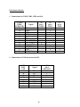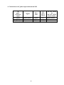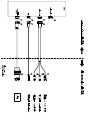
1
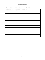
MODEL 2850
USER MANUAL
LAVERSAB, INC.
505 GILLINGHAM LANE
SUGAR LAND, TEXAS, 77478
(281) 325 8300
FAX: (281) 325 8399
Email: [email protected]
Document Number : 125-9168A
Date: October 26, 2011
WARRANTY
Laversab, Inc. warrants its products to conform to or exceed the specifications as set
forth in its catalogs in use at the time of sale and reserves the right, at its own discretion,
without notice and without making similar changes in articles previously manufactured,
to make changes in materials, designs, finish, or specifications. Laversab, Inc. warrants
products of its own factory against defects of material or workmanship for a period of one
year from date of sale.
Liability of Laversab, Inc. under this warranty shall be limited to replacing, free of
charge (FOB Houston, Texas), any such parts proving defective within the period of this
warranty, but Laversab, Inc. will not be responsible for transportation charges,
consequential or incidental damages. No liability is assumed by Laversab for damages
that are caused by misuse or abuse of the product.
The warranty of Laversab, Inc. is not made for products manufactured by others
which are illustrated and described in Laversab catalogs or incorporated in Laversab
products in essentially the same form as supplied by the original manufacturer.
i
COPYRIGHT NOTICE
Copyright (c) 2003-2011 by Laversab, Inc. All rights reserved. The content of this manual
may not be reproduced in any form by any means, in part or in whole, without prior
written permission of Laversab, Inc.
DISCLAIMER
No representations or warranties are made with respect to the contents of this user
manual. Further, Laversab, Inc. reserves the right to revise this manual and to make
changes from time to time in the content hereof without obligation to notify any person of
such revision.
ii
REVISION HISTORY
Document No.
Release Date
125-9068 Rev. A
10/26/2011
Description
2850 User Manual
iii
WARNING
THE 2850 USES LINE VOLTAGES FOR ITS OPERATION WHICH ARE POTENTIALLY
DANGEROUS. IMPROPER OPERATION OF THIS EQUIPMENT MAY RESULT IN
PERSONAL INJURY OR LOSS OF LIFE. HENCE THE EQUIPMENT DESCRIBED IN
THIS MANUAL SHOULD BE OPERATED ONLY BY PERSONNEL TRAINED IN
PROCEDURES THAT WILL ASSURE SAFETY TO THEMSELVES, TO OTHERS AND TO
THE EQUIPMENT.
BEFORE PERFORMING ANY MAINTENANCE, TURN THE POWER OFF AND
DISCONNECT THE POWER CORD FROM THE POWER SOURCE.
EXPLOSION HAZARD BATTERIES MUST ONLY BE CHANGED IN AN AREA
KNOWN TO BE NON HAZARDOUS.
DO NOT CONNECT OR DISCONNECT WHILE CIRCUIT IS ALIVE UNLESS AREA IS
KNOWN TO BE NON-HAZARDOUS.
AVERTISSEMENT
LA 2850 UTILISE UNE TENSION LIGNE POUR SON OPERATION QUI SONT
POTENTIELLEMENT DANGEREUX. MAUVAIS FONCTIONNEMENT DE CET
APPAREIL PEUT PROVOQUER DES BLESSURES OU DES PERTES DE VIE. DONC
L'ÉQUIPEMENT DÉCRIT DANS CE MANUEL DOIT ÊTRE UTILISÉ UNIQUEMENT
PAR UN PERSONNEL QUALIFIÉ DANS DES PROCÉDURES QUI ASSURERONT LA
SALUBRITÉ EUX-MÊMES, AUX AUTRES ET À L'EQUIPEMENT.
AVANT DE TOUT ENTRETIEN, ÉTEIGNEZ L’APPAREIL HORS TENSION ET
DÉBRANCHEZ LE CORDON D’ALIMENTATION LA SOURCE D'ALIMENTATION
RISQUE D’EXPLOSION AFIN D’ ÉVITER TOUT RISQUE D’EXPLOSSION, S’ASSURER
QUE L’EMPLACEMENT EST DÉSIGNÉ NON DANGEREUX AVAN DE CHANGER
LA BATTERIE.
RISQUE D’EXPLOSION, NE PAS DEBRANCHER TANT QUE LE CIRCUIT EST SOUS
TENSION, A MOINS QU’IL NE S’AGISSE D’UN EMPLACEMENT NON
DANGEREUX.
iv
TABLE OF CONTENTS
Warranty
.............................................................................................................................
Copyright notice, disclaimer ...............................................................................................
Revision History ...................................................................................................................
Warning
.............................................................................................................................
i
ii
iii
iv
Section 1:
Introduction
Section 2:
Safety .............................................................................................................. 3
Section 3:
Installation ..................................................................................................... 5
3.1
3.2
3.3
.................................................................................................. 1
Loading Software .................................................................................................
Mounting the 2850 ................................................................................................
Connections to the 2850 .....................................................................................
3.3.1 Non-hazardous locations ............................................................................
3.3.2 Hazardous locations ....................................................................................
5
5
7
7
7
Section 4:
Typical Use
................................................................................................... 9
Section 5:
Removal ......................................................................................................... 10
Section 6:
Maintenance & Servicing
Appendix A:
Appendix B:
Appendix C:
Appendix D:
External Connections in Hazardous Locations ......................................
Drawings : Cables for Non-Hazardous Locations ..................................
2850-M1 alternate connectors pinout .......................................................
Repair and Return Policies .........................................................................
........................................................................... 11
v
12
20
22
24
SECTION 1
INTRODUCTION
The model 2850 Industrial computer is a PC-compatible computer that is specifically
designed for use in hazardous locations that are classified as Class 1 Division 2. Typical
applications include rig-floor monitoring and use in chemical plants. The rugged yet,
compact design of the 2850 makes it easy to install and remove off rig-floors and makes it
suitable for use under all weather conditions. The 2850 is shown if Figure 1.1.
Features:
•
CPU: Atom single- or dual-core, up to 1.8 GHz
•
15.0” sunlight readable display with 1024 x 768 resolution
•
Auto-dimming of display brightness based on ambient light
•
High resolution resistive Touch-screen with optical polarizer for outdoor
operation
•
Up to 2 GB RAM for single-core and up to 4 GB for dual-core; 160 GB SATA
HDD; Optional 64 GB SATA SSD (solid-state drive)
•
Operating power : 90-260 VAC, 50/60 Hz, 70 Watts
•
Internal Heater power : 90-260 VAC, 50/60 Hz, 150 VA
•
Operating temperature : –40oC to 50oC
•
Storage temperature : –40oC to 50oC
•
Operating / Non-operating shock : 50 G, 11 ms half-sine
•
Operating / Non-operating vibration : 1.5G RMS, 5 to 500 Hz
•
Humidity : 5 to 100%
•
Serial port, two USB ports, through sealed Cannon connector
•
One Ethernet port, through sealed Cannon connector
•
Sealed enclosure allows operation outdoors
•
Mounting holes provided for both bottom-mount or back-mount
•
Weight : 21 lbs
•
Dimensions : 15” (w) x 12.5” (h) x 4” (d)
1
SECTION 2
SAFETY
The following safety instructions must be followed to prevent possible hazards of fire,
electrical shock and bodily harm.
1.
WARNING : The model 2850 must be connected to an appropriate power source
as indicated on the information label on the rear panel of the unit.
2
WARNING: The unit must never be opened or left open in a hazardous location.
The rear panel and the top heat sink must be securely fastened before the unit is
introduced into a hazardous location.
3
WARNING: Do not install or operate this unit in an area where the temperature is
outside the limits indicated on the information label on the rear panel of the unit.
4
WARNING: All connections made to the unit must strictly adhere to the rules set
forth in Section 3.2 of this manual.
5
WARNING: There are no user-serviceable components inside this unit. The unit
must not be opened to repair or replace any components. If components are
repaired or replaced by the user, the unit may no longer be suitable for use in
hazardous locations and may become an explosion hazard.
6
WARNING: The Model 2850 is suitable for use only in Class I Division 2 (Groups
C and D) hazardous locations and non-hazardous locations.
7
WARNING: The Model 2850 cannot be connected to any signal going to an area
of higher classification than Class I Division 2 (Groups C-D).
8
CAUTION: Do not install the unit in an unstable manner that could cause it to tip
over.
9
CAUTION: Follow all instructions and warnings marked on the unit and also
those included in this manual.
3
Approvals
The Model 2850 conforms to the following standards:
UL60950 / CSA 60950
CAN/CSA – C22.2 No. 60950.00
UL 1604
CAN / CSA – C22.2 No. 213-M1987
4
SECTION 3
INSTALLATION
The installation process consists of the following :
a.
b.
c.
3.1
Loading the application software onto the 2850.
Mounting the 2850 on-site using an appropriate mounting bracket.
Making the connections to the 2850.
Loading software
The 2850 is provided with a Windows operating system that is pre-installed, with the
network enabled. All software must be loaded through the network port on the bottom
panel of the unit. As a secondary option, the unit has two USB ports (USB2.0 std.) that can
also be used to load software. It is not necessary to open the unit to load the software.
If software modifications require that the unit be opened to have access to internal
connectors, this must be done at the Laversab facility. If the unit is opened by the user
then it may severely impair the hazardous location classification of the unit.
3.2
Mounting the 2850
A suitable mounting bracket may be fabricated by the user based on the user’s mounting
requirements. Figure 3.1 shows a suggested mounting bracket for mounting the 2850 on a
flat plate or on a pipe stand with an optional adapter. The mounting bracket should be
fastened to the four mounting studs provided on the rear panel of the unit. The studs are
3/4 inch in length with a thread size of 5/16 – 18.
WARNING: The mounting bracket should not cover any of the markings and warnings
on the rear panel of the 2850.
WARNING: The mounting bracket should not cover any of the connectors or the circuit
breakers on the rear panel of the 2850.
CAUTION:
of the 2850.
The mounting bracket should not cover the photo-resistor lens on the front
5
3.3
Connections to the 2850
There is a significant difference on how connections may be made to the 2850 based on
whether the location of use is hazardous or non-hazardous.
3.3.1
Non-hazardous locations
The unit is provided with three external cables.
1.
2.
3.
“AC POWER” cable
“LAN” cable
“COMs/USBs” cable
WARNING: All the above cables are for use in non-hazardous locations only. Using
these cables in hazardous locations may impair the hazardous location classification of the
unit.
The AC power cable is terminated in a NEMA 5-15 plug and may only be connected to a
power source of 110/220 VAC, 50/60 Hz.
The LAN cable is terminated in a standard RJ-45 plug which must be connected to any
10/100 M-bit Ethernet LAN device that adheres to the IEEE 802.3 standard.
The COMs/USBs cable is split into three separate terminations. The termination labeled
‘USB1’ and ‘USB2’ are USB type-A male connectors that may be connected to any standard
USB device. The terminations labeled ‘COM1’ provides a DB-9 male connector which
may be connected to any EIA RS-232C connection.
The drawings and pin-outs of these cables are provided in Appendix B.
3.3.2
Hazardous locations
The user is required to provide all the external cables for use in hazardous locations. The
cabling and connection methods and restrictions are detailed below. The Control
Drawing for all connections to the 2850 is shown in Figure A-1.
1. AC Power cable:
The pin-out for the AC POWER INPUT connector on the rear panel of the 2850 is
provided in Appendix A. The mating connector is also listed in Appendix A. The
External 110 VAC, 60Hz or 220 VAC, 50 Hz power source must be located in a nonhazardous location.
7
WARNING: The power cord used must adhere to the following rules:
a. The power cord must be approved for “extra hard” usage.
b. The power cord must be terminated into the external AC power source as shown in
Figure A-1.
WARNING: Do not connect or disconnect the AC POWER INPUT connector when the
circuits are energized.
WARNING: Ensure that the external AC power source is OFF before connecting or
disconnecting the AC POWER INPUT connector.
2. LAN cable
The pin-out for the LAN connector on the rear panel of the 2850 is provided in Appendix
A. The mating connector is also listed in Appendix A.
WARNING: The LAN cable may only be terminated into a 10/100 M-bit Ethernet LAN
device that adheres to the IEEE 802.3 standard. The Control Drawing for this connection is
shown in Figure A-1.
A shielded CAT-5 cable may be used to provide this connection to the 2850. Although no
special cable protection is required in a hazardous location, it is recommended that the
LAN cable be run in the same rigid conduit used for the power cable.
WARNING: Do not connect or disconnect the LAN connector when the circuits are
energized.
3. COMs/USBs cable
WARNING: The USB part of the cable may only be terminated into a connection that
adheres to the USB 2.0 standard. The Control Drawing for this connection is shown in
Figure A-1.
WARNING: The Serial part of the cable may only be terminated into a connection that
adheres to the EIA RS-232C standard. The Control Drawing for this connection is shown
in Figure A-1.
WARNING: Do not connect or disconnect the USB/Serial connector when the circuits
are energized.
A shielded cable may be used to provide the USB/Serial connection to the 2850.
8
SECTION 4
TYPICAL USE
After the 2850 has been installed per the instructions provided in Section 3 of this manual,
the unit may be turned ON for operation in the following sequence:
1. Turn ON the external power source.
2. Turn ON the devices that provide the Ethernet, USB and RS232 interfaces in the
non-hazardous location.
If the ambient temperature is below 5oC , the 2850 may not boot up immediately. The
internal heaters and fans will start operating and attempt to bring the temperature inside
the 2850 above 5oC. During this process, the heaters LED will turn on indicating that the
heaters are operating. The heaters may operate for up to 30 minutes before the internal
temperature rises above 5oC, at which point the computer section of the 2850 will boot up.
When the computer section of the 2850 is starting to boot up, the backlight on the display
will turn on and the display will be completely white for a period of about 2 to 5 seconds.
Thereafter, the boot-up screen will be displayed.
During normal use, the application software will communicate through the LAN and/or
the Serial port and show the necessary information on the display. A USB keyboard
and/or mouse may be used as an input device by the user, but typically, the touch-screen
on the front panel is the only input device used.
CAUTION: Do not use a sharp object to “touch” the touch-screen. Scratching the
touch-screen surface in any way will cause the touch-screen to malfunction.
The touch-screen may be used for cursor movement, icon selection and “dragging”
windows/dialogue boxes. The “right-click” function of the touch-screen is activated upon
holding the touch for about 2 seconds. There is an on-screen (virtual) keyboard that may
be used at anytime as part of the touch-screen. It’s right edge is visible at all times on the
right edge of the Desktop, and maybe activated by dragging it to the center of the screen.
The photo-resistor lens on the front of the unit must be kept unobstructed and clean
during normal operation. This will allow the auto-dimming circuit to properly regulate
the brightness of the display based on the ambient light conditions.
WARNING: During normal operation the user must not alter any of the connections to
the 2850. Failure to do so may create an explosion hazard.
9
SECTION 5
REMOVAL
While removing (de-installing) the 2850 from normal operation, follow the sequence
shown below:
WARNING: Do not disconnect ANY connectors while circuits are energized.
1. Turn OFF the external AC power source located in the non-hazardous area.
2. Turn OFF the devices in the non-hazardous area that provide the LAN, USB and
RS232 interfaces to the 2850.
3. Disconnect the AC POWER INPUT connector from the 2850
4. Disconnect the LAN connector
5. Disconnect the USB connector.
6. Disconnect the Serial connector.
7. Remove the 2850 from its mounting stand and move it out of the hazardous
location.
WARNING: Not following the above sequence may induce an explosion hazard.
10
SECTION 6
MAINTENANCE & SERVICING
6.1
MAINTENANCE
The 2850 requires the following maintenance procedures to be performed regularly:
a. Clean the touch-screen with water or any commercial window cleaner, using a
clean, soft, lint-free cloth. Care must be taken not to scratch the touch-screen
during the cleaning process. Do not use any abrasive substance, or any organic
solvents to clean the touch-screen.
b. Clean the photo-resistor lens in the same manner as described in ‘a.’ above.
WARNING: Do NOT pressure-wash the 2850.
6.2
SERVICING
CAUTION: Risk of explosion if battery is replaced by an incorrect type. Dispose off used
batteries in the prescribed manner.
WARNING: Substitution of components is strictly prohibited
WARNING: The Model 2850 does not contain any user-serviceable or user-replaceable
components. The 2850 must not be opened by the user in an attempt to repair or service
the unit. Doing so may severely impair the hazardous location classification of the unit.
All repairs and servicing of the unit can only be performed at the Laversab facility.
11
APPENDIX A
EXTERNAL CONNECTIONS IN HAZARDOUS LOCATIONS
The external connectors, pin-outs and connection details shown below reference the
Control Drawing shown in Figure A-1. Individual connector drawings are shown in
Figures A2 through A4.
“A” : COMs/USBs Connector on 2850
Connector type :
ITT Cannon KPT02A14-12S
Mating connector “E” :
ITT Cannon KPT06A14-12P
Pin-out:
Please refer to Figure A-2
Pin #
A
B
C
D
E
F
G
H
J
K
L
M
Signal
N.C.
USB1 USB1 +
USB2 +
N.C.
USB2 RX (COM1)
TX (COM1)
GND (COM1)
+5V(USB 1)
GND
+5V(USB 2)
12
“B” : LAN Connector on 2850
Connector type :
ITT Cannon KPT02A12-8S
Mating connector “F” :
ITT Cannon KPT06J12-8P
Pin-out:
Please refer to Figure A-4
Pin #
A
B
C
D
E
F
G
H
Signal
TD +
TD RD RD +
N.C.
N.C.
N.C.
N.C.
“C” : AC Power Input Connector on 2850
Connector type :
Brad Harrison 1R3G06A20A120 , 3 pin male receptacle
Mating connector “H”:
Brad Harrison 103000A01F060 cable with molded
connector
Pin-out:
Please refer to Figure A-5
Note: Pins are not marked on the connector. The pin numbers shown indicate the wire
color used for each pin internally.
Pin #
G (Green)
W (White)
B (Black)
Signal
Earth Ground
Neutral
Line
13
“D” : RS-232 connector in non-hazardous location
Connector type :
Standard DB-9 male
Mating connector : Standard DB-9 female
Pin-out:
Pin #
1
2
3
4
5
6
7
8
9
Signal
N.C.
RX
TX
N.C.
GND
N.C.
N.C.
N.C.
N.C.
“E”, “F” : USB connectors in non-hazardous location
Connector type :
Standard USB A socket
Mating connector : Standard USB A connector .
Pin-out:
Pin #
1
2
3
4
Signal
+5 V
DD+
GND
14
“G” : LAN connector in non-hazardous location
Connector type :
Standard RJ-45 plug
Mating connector : Standard RJ-45 socket on barrier box
Pin-out:
Pin #
1
2
3
4
5
6
7
8
Signal
TD +
TD RD +
N.C.
N.C.
RD N.C.
N.C.
“H” : AC connector in non-hazardous location
Connector type :
Standard NEMA L6-15 Plug
Mating connector : Standard NEMA L6-15 socket/receptacle
Pin-out:
Pin #
X
Y
G
Signal
Line
Neutral
Earth Ground
15
Interconnect details:
1. Connections to COM1, USB1, USB2 on 2850
“I” pin #
COM1 /
USB1,USB2
A
B
C
D
E
F
G
H
J
K
L
M
Signal
“D”
pin #
COM1
N.C.
USB1 USB1 +
USB2 +
N.C.
USB2 RX (COM1)
TX (COM1)
GND (COM1)
+5V(USB 1)
GND
+5V(USB 2)
“E”
pin #
USB1
2
3
3
2
2
3
5
1
4
2. Connections to LAN connector on 2850
“J”
Pin #
LAN
A
B
C
D
E
F
G
H
“F”
pin #
USB2
“G”
pin #
RJ45 LAN
1
2
6
3
Signal
TD +
TD RD RD +
N.C
N.C.
N.C.
N.C.
16
4
1
4. Connections to AC power input connector on 2850
“K”
pin #
AC Power
input
G (Green)
W (White)
B (Black)
Signal
Earth Ground
Neutral
Line
17
Wire
color
“H”
pin #
LP6-15
Green
White
Black
G
Y
X
110 VAC, 60 Hz
or
220 VAC, 50 Hz
Power source
Earth Ground
Neutral
Line
APPENDIX B
CABLES FOR NON-HAZARDOUS LOCATIONS
Four cables are provided with the 2850 for use in non-hazardous locations only.
1. COMs/USBs cable. Please refer to Figure B-1
2. LAN cable. Please refer to Figure B-2
3. AC Power input cable for 110 VAC, 60 Hz only. Please refer to Figure B-3
20
APPENDIX C
2850-M1 ALTERNATE CONNECTORS PINOUT
“A” : COMs/USBs Connector on 2850-M1
Connector type :
ITT Cannon KPT02A14-12S
Mating connector “E” :
ITT Cannon KPT06A14-12P
Pin-out:
Please refer to Figure A-2
Pin #
A
B
C
D
E
F
G
H
J
K
L
M
Signal
N.C.
USB1 USB1 +
USB2 +
N.C.
USB2 RX (COM1)
TX (COM1)
GND (COM1)
+5V(USB 1)
GND
+5V(USB 2)
“B” : PRESSURE Tx Connector on 2850-M1
Connector type :
ITT Cannon KPT02A12-8S
Mating connector “F” :
ITT Cannon KPT06J12-8P
Pin-out:
Please refer to Figure A-3
22
Pin #
A
B
C
D
E
F
G
H
J
K
L
M
N
P
R
S
T
U
V
Signal
GND
N.C.
N.C.
N.C.
N.C.
GND
N.C.
N.C.
N.C.
N.C.
N.C.
N.C.
N.C.
N.C.
N.C.
TX IN
N.C.
N.C.
TX DRIVE
“C” : LAN Connector on 2850 M-1
Connector type :
ITT Cannon KPT02A12-8S
Mating connector “F” :
ITT Cannon KPT06J12-8P
Pin-out:
Please refer to Figure A-4
Pin #
A
B
C
D
E
F
G
H
Signal
TD +
TD RD RD +
Q_BUS
24V
24V
GND
23
APPENDIX D
REPAIR AND RETURN POLICIES
If it is determined that the product is defective, please call Laversab customer service
department: (281) 325 8300 or e-mail <[email protected]> for further assistance.
Before shipping any equipment to Laversab for repair, please call the customer service
department at (281) 325 8300 or e-mail to <[email protected]>. Please include a
description of the problem that has been identified when returning defective equipment.
Ship equipment to :
Laversab, Inc.
505 Gillingham Lane
Sugar Land, Texas, 77478
U.S.A.
24