1
HR2536/HR2537 (ACL 3012)
HR2538/HR2539 (ACL 3016)
Atlantic Coast Line U25C Phase IIIb
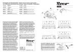
LISTA RICAMBI / ERSATZTEILLISTE / LIST OF SPARES
3
1
Item No.
Teil-Nr.
2
Description
Bezeichnung
Spare part ref.
Ersatzteil-Nr.
1
Bodyshell accesories
Gehäusezubehörteile
HR2536/01
2
Bodyshell grills
Geätzte Gitter
HR2536/02
3
Diffusers
Lichtleiter
HR2528/03
4
Body shell (#3012)
Gehäuse (#3012)
HR2536/04
5
Body shell (#3016)
Gehäuse (#3016)
HR2538/05
6
Couplers pack
Kupplungssatz
HR2520/06
7
Additional parts for buffer beam
Zurüstteile für Pufferbohle
HR2536/07
8
Photo-etched steps
Geätzte Trittstufen
HR2536/08
9
Walkway handrails
Umlaufgeländer
HR2536/09
10
LED PCB’s
LED-Platinen Spitzenbeleuchtung
HR2520/10
11
Main PCB incl. digital dummy plug
Hauptleiterplatte inkl. Schnittstelle
HR2520/11
12
Worm gears
Antriebsschnecken
HR2520/12
13
Cardanic shafts
Kardanwellen
HR2520/13
14
Motor + motor support
Motor + Motorhalterung
HR2520/14
15
Gear Box Cover Pack
Getriebe-Abdecksatz
HR2536/15
16
Gear boxes with pick-ups
Drehgestellrahmen mit Stromabnahmekontakten
HR2536/16
17
Gears
Zahnräder
HR2520/17
18
Bogie base
Drehgestellbodenabdeckung
HR2536/18
19
Bogie cover
Drehgestellboden
HR2536/19
20
Complete bogies
Drehgestelle, komplett
HR2536/20
6
7
5
4
8
3
9
7
10
6
23
12
8
11
13
14
13
10
12
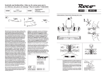
Remove dummy plug to fit digital decoder
Zum Einbau des Digital-Decoders
Dummystecker entfernen
www.hornbyinternational.com
HORNBY HOBBIES LTD
Westwood Industrial Estate,
Margate, Kent, CT9 4JX
United Kingdom
HORNBY ESPAÑA S.A.
Federico Chueca, s/n
28806 Alcalá de Henares
Madrid, España
HORNBY ITALIA S.r.l,
via Ferri, 14/16
25010 Borgosatollo
Brescia, Italia
HORNBY FRANCE SAS,
Parc d’activites de Gomberville,
78114 Magny les Hameaux
France
HORNBY DEUTSCHLAND GmbH,
Ostpreußenstraße 13,
96472 Rödental
Deutschland
HORNBY AMERICA
3900 C-2 Industry Drive East
Fife, WA 98424
USA
14+
Issued April 2014
Service Sheet HRBS-406
HR2536/HR2537 (ACL 3012)
HR2538/HR2539 (ACL 3016)
Atlantic Coast Line U25C Phase IIIb
15
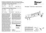
LISTA RICAMBI / ERSATZTEILLISTE / LIST OF SPARES
Item No.
Teil-Nr.
17
16
Description
Bezeichnung
Spare part ref.
Ersatzteil-Nr.
21
Complete bogie
Drehgestell, komplett
HR2536/21
22
Wheel set
Radsätze
HR2520/22
23
Screws
Schrauben
HR2520/23
18
21
19
15
17
22
2.
18
3.
20
Rivarossi HO Scale U25C Assembly and Dis-Assembly instructions
1.
2.
1.
1.
www.hornbyinternational.com
HORNBY HOBBIES LTD
Westwood Industrial Estate,
Margate, Kent, CT9 4JX
United Kingdom
HORNBY ESPAÑA S.A.
Federico Chueca, s/n
28806 Alcalá de Henares
Madrid, España
HORNBY ITALIA S.r.l,
via Ferri, 14/16
25010 Borgosatollo
Brescia, Italia
HORNBY FRANCE SAS,
Parc d’activites de Gomberville,
78114 Magny les Hameaux
France
HORNBY DEUTSCHLAND GmbH,
Ostpreußenstraße 13,
96472 Rödental
Deutschland
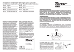
To Dis-Assemble:
1. Remove 4 screws (short) on either end of the fuel tank.
2. Remove coupler pocket screws (long) at each end and remove
couplers from each end of unit.
3. Gently grasp body shell and lift straight up to uncover mechanism.
To Re-Assemble:
1. Gently grasp body shell and place on mechanism- taking care to line
up screw holes.
2. Insert couplers from the ends and line up screw holes – insert longer
screws to attach couplers.
3. Insert and secure 4 short screws at either end of fuel tank.
HORNBY AMERICA
3900 C-2 Industry Drive East
Fife, WA 98424
USA
14+
Issued April 2014
Service Sheet HRBS-406
www.HornbyAmerica.com
Rivarossi Sound Equipped GE U25C
Quick Start Guide
Please go to www.LokSound.com for a complete user manual
You have just purchased a Top of the Line Locomotive with one of the most State of Art Digital Sound Decoders on the Market. With nothing more than your Digital Command Station you have
the option of 12 separate horns,2 bells, and 2 brakesqueals. All changeable by one CV. No booster is needed! Each individual sound has a separate volume control, and up to 8 sounds can be
played at one time! Not only that, but as new sounds become available and firmware gets updated, you can at anytime, hook up to our famous LokProgrammer and update your decoder! Along
with outstanding sound, ALL LokSound decoders give you the benefit of the Industry Leading ESU Motor control. You’ll see the difference instantly as the engine smoothly accelerates across your
pike! Don’t forget you also have the option to use one of our MANY lighting effects on any one of your 8(!) function outputs!
Technical data LokSound Select Decoder
Default Function Assignments
Diesel Prime Movers
Operational modes:
Function key Effect
Prime Mover name
F0
F1
F2
F3
F4
F5
F6
F7
F8
F9
F10
F11
F12
F13
F14
F15
F16
F17
F18
F19
NMRA/DCC with 14, 28, 128 speed steps
2-digit (short) or 4-digit (long) addresses
Analog DC (Dual mode, de-selectable)
Automatic recognition of operational mode
Supports ALL NMRA programming modes
Power:
Runs all DC and coreless motors
Silent, safe 31,25 kHz pulse width frequency BEMF
Motor output overload protected
Function outputs:
8 outputs
250 mA load per output
Outputs short-circuit protected
Sound:
Audio amplifier: 2W @4Ohms load
Speaker impendance 4-8 Ohms
Memory Capacity 32MBit
8 Sound Channels, All playable at once!
Over 20 different sounds!
Directional Headlights
Bell
Playable Airhorn (see Air Horn Chart)
Coupler Clank
Dynamic Brake
Number Board Lights
Emergency Light 1
Emergency Light 2
Prime Mover Sound On/Off (MUTE)
Manual Notching Up
Manual Notching Down
Compressor
Slow Spitter Valve
Switching Mode
Sanding Valve
Short Air Let Off
Radiator Fan
Brake Set/Release
Fast Spitter Valve
Spitters on Shut (press to disable)
Dimensions:
1.02 x 0.62 x 0.18 inch (25.5 x 15.5 x 4.5 mm)
Extended Addressing
Most Command Stations will give you the option to enter a 4 Digit Extended Address. Please refer to your
Command Station’s Manual for guidance as to how to do this. If your command Station does not have this
feature a full list of values and instructions are available on line at www.loksound.com
Start Delay
While pulling a train a Prototype Locomotive will not move until the Prime mover has worked up enough power to provide the proper
amount of electricity to the traction motors. For this reason when the LokSound Select sound is idling and you turn up the throttle, the
locomotive begins to move only after the Diesel engine has reached notch1. Although this behavior is very prototypical, one might not like
it because it causes some delay. You can disable this startup delay by simply Changing CV124 to a value of 16. This will cause the LokSound
Select decoder to immediately start moving when the throttle is turned up. However, the start up sound will not be prototypically synced
with the motion anymore. Instead it will start oving immediately like most other decoders.
Sound on/Sound Off (F8 Operation)
You will notice quickly that the F8 button will work differently than what you may be used to. This is done for two reasons. First so that you can
hear both the start and Shut down sequences without any CV changes. Also so that upon power up the drain on your command station is not
as great. Sound decoders draw quite a bit of power upon start up. Having the sound off initially when the layout is powered up is a much more
efficient way on doing things. This can save your command station from an early demise! You may be used to other manufacturers who do this
backwards. If you prefer you can easily reverse this feature in LokSound decoders. Simply Change CV32 to 2, then CV403 to 32. Please note also
that F8 only controls the prime mover sounds. On a real engine, as long as there is air, the bell and the horn will work when the prime mover is
off! This is also the case in LokSound Decoders!
Decoder-Reset
Diesel sound Volume Control table
Function (Diesel)
CV
Range
Default
Master volume control
Diesel Volume Control
Horn Volume Control
Bell Volume Control
Coupler Sound Volume Control
Dynamic Brake Volume Control
Air Compressor Volume Control
Brake Set / Brake Release
Sanding valve Volume Control
Short Air Let Off Volume Control
Fast Spitter Valve Volume Control
Slow Spitter Valve Volume Control
Shutdown Spitter Valve Volume Control
Random sounds
63
259
275
283
291
299
307
347
355
379
371
387
395
451
0 - 192
0 - 128
0 - 128
0 - 128
0 - 128
0 - 128
0 - 128
0 - 128
0 - 128
0 - 128
0 - 128
0 - 128
0 - 128
0 - 128
192
128
95
70
128
65
64
40
128
128
80
80
80
40
Write value 08 into CV 08.
From time to time you may have the need to reset the
decoder in your new Locomotive. Setting CV08 to a value
of 08 will accomplish this. Be aware though that all user
settings will be set back to factory defaults with this
process. Your address will again become 03.
BE SURE CV 32 IS SET TO 1 BEFORE CHANGING CVs 257-511
HORNBY HOBBIES LTD Westwood Industrial Estate, Margate, Kent, CT9 4JX, United Kingdom
HORNBY ESPAÑA S.A. Federico Chueca, s/n, 28806 Alcalá de Henares, Madrid, España
HORNBY ITALIA S.r.l, via Ferri, 14/16, 25010 Borgosatollo, Brescia, Italia
HORNBY FRANCE SAS, Parc d’activites de Gomberville, 78114, Magny les Hameaux, France
HORNBY DEUTSCHLAND GmbH, Ostpreußenstraße 13, 96472 Rödental, Deutschland
HORNBY AMERICA INC, 3900-C2 Industry Drive, East, FIFE, WA 98424, USA
www.hornbyinternational.com
CV 48 value
There is only one GE 16cyl FDL Prime Mover sound on this
decoder. Please use a Value of 0 for this part of the CV48
calculation. (See Below)
Diesel Decoders Airhorns
Airhorn name
Nathan K5LA
Nathan K3L
Nathan M5 - ACL
Nathan P3 - Northern Pacific
Nathan P5A
Leslie S2M - CB&Q
Leslie RS3L - L&N
Leslie S3L - PRR - CR - PC
Leslie S5T
Leslie M3
Leslie RS3K
Nathan K5H
Leslie S3L
Nathan Holden M3H
Leslie S2M
Nathan P3
12*3to
choose from!*
duplicates due to avalable memory
3
Diesel Decoders Bell Types
Bell Type
Slow Bell
Fast Bell
2 to choose from!
0
Diesel Decoders Brake Squeals
Brake Squeal Version
Brake Squeal Version #1
Brake Squeal Version #2
CV 48 value
0
1
2
3
Default
4
5
6
7
8
9
10
11
12
13
14
15
CV 48 value
0
Default
64
2 to choose from!
0
CV 48 value
0
Default
128
Sound Choices
This Factory equipped LokSound Digital Sound Decoder was built
specifically to be correct for the Prototype of the model. You may find
however that you would like different Sounds. All sounds can be
changed with CV48 and your Command Station.
CV 48 is calculated by adding the Prime mover, the horn, the Bell,
and the brake squeal selection you would like in your model. By
adding your choices from the charts above you will arrive at the value
to put in CV 48.
Default Example:
Prime Mover = 0
Airhorn = 3
Bell = 0
Brake Squeal = 0
Total = 3
CV48 Value = 3
A full PDF Manual can be found at www.LokSound.com.
Please refer to the LokSound Select Manual.
As a Reference NO BOOSTER is needed for programming.
Service Sheet HRBD-58
Issued July 2014