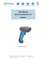
1
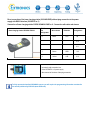
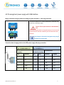
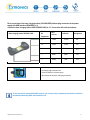
User Manual Bluetooth Handheld Scanner iSCAN201 Date: 27.03.2015 Table of contents 1 Important notes on the Operating Instructions ................................................................................................ 2 1.1 Safety information.......................................................................................................................................... 2 1.2 Notes on the Operating Instructions .............................................................................................................. 3 1.3 General notes of caution ............................................................................................................................... 4 2 Product information ........................................................................................................................................... 6 2.1 Manufacturer ................................................................................................................................................. 6 2.2 Explosion protection ...................................................................................................................................... 6 2.3 Scanner technical data .................................................................................................................................. 6 2.4 Base charging station technical data ............................................................................................................. 7 2.5 Components .................................................................................................................................................. 8 2.6 Serial numbers .............................................................................................................................................. 8 2.7 Application ..................................................................................................................................................... 8 3 System assembly ................................................................................................................................................ 9 3.1 System assembly 1 ....................................................................................................................................... 9 3.2 System Assembly 2 ..................................................................................................................................... 10 3.3 Cable range in system assembly 1 .............................................................................................................. 11 3.4 Cable range in system assembly 2 .............................................................................................................. 11 4 Step-by-step guide on installation and operation .......................................................................................... 12 4.1 Preparation handheld iSCAN201 scanner for system assembly 1 and 2 .................................................... 12 4.2 Using the base charging station for system assembly 1 (hazardous areas) ................................................ 14 4.3 Using the base charging station for system assembly 2 (non-hazardous areas) ......................................... 15 4.4 Pin assignment power supply with RS232 interface .................................................................................... 16 4.5 Pin assignment power supply with USB interface........................................................................................ 18 5 Attachment ........................................................................................................................................................ 20 5.1 EC type examination certificate: ISCAN201 and ISCAN201 base charging station..................................... 20 5.2 EC type examination certificate: Power supply ISCANPS ........................................................................... 22 6 Contact .............................................................................................................................................................. 26 Operating Instructions_iSCAN201_001 1 Important notes on the Operating Instructions 1.1 Safety information Warnings are highlighted by a special symbol and a different font colour: Non-compliance may result in life-threatening situations. This warning must be heeded. Danger This type of warning concerns dangerous situations that may result in minor injuries. Warning Important and helpful notes and information. Info Operating Instructions_iSCAN201_001 2 1.2 Notes on the Operating Instructions Before starting up the equipment please read the Manual thoroughly. The Operating Instructions contain important information on functionality as well as safety rules. If these are not heeded, normal operations within hazardous areas cannot be guaranteed. The notes contained in this manual are important for starting up and operating the product. These instructions may be updated at any time. Extronics Limited reserves the right to make changes to this document. Before they use the product, users must ensure that they have the most up-to-date version of the operating instructions. To make sure this is the case, please check Extronics’ website, www.extronics.com, or contact one of the company's staff. The drawings contained in these operating instructions are for illustration purposes only and may differ somewhat from the actual design. No changes may be made to the device that were not intended or approved by Extronics Limited. If the handheld scanner is not used properly, the operating permission for hazardous areas may lapse for the device in question. Non-adherence to the instructions will void any warranty. For the full commission of the iSCAN201 handheld scanner, the programming information contained in the manual issued by SICK AG (www.SICK.com) is also required. Operating Instructions_iSCAN201_001 3 1.3 General notes of caution Caution / Notes Notes on installation Operating Instructions_iSCAN201_001 The devices may only be operated when fully assembled. In hazardous areas, the devices must not be wiped or cleaned with a dry cloth. The device must be switched off immediately if it is likely that it can no longer be operated safely as a result of damaging impact or general peculiarities (such as ingress of water or other fluids, temperatures outside of the specified range, etc.). General statutory requirements or health and safety rules and accident prevention guidelines and environmental laws must be adhered to (e.g. the German Occupational Health and Safety regulation). Users must not open the device. Users must not make any changes to the device. Components may not be exchanged or replaced. If non-specified components are used, explosion protection is no longer guaranteed. Ensure safe handling with firm footing and sufficient room for movement. If the enclosure is in any way damaged the device must be removed from the hazardous area immediately. In accordance with IEC 60079-19 and IEC 60079-17, operators of electrical installation in hazardous areas are obliged to have them serviced by qualified electricians. Do not insert any sharp objects into the enclosure or any other openings of the handheld barcode scanner. Any openings at the device may not be covered or blocked. The device and any accessories must be properly disposed of, i.e. as legally specified, for example by a certified company. Electrical plants are subject to certain regulations concerning installation and operation (e.g. RL 99/92/EG, RL 94/9EG, or the national rules such as IEC 60 079-14 and VDE 0100). In the hazardous area it is the operator's responsibility to carry out any repair and maintenance in compliance with applicable rules. 4 Caution on laser devices Devices fitted with laser fall under standards US 21 CFR 1040.10 and EN 60825-1. The laser's classification is stated on a plate affixed to the device. Class 1 lasers are deemed inherently safe during normal use, but users must not look directly into the light source. The following declaration is required by American and international laws: Usage of control elements, adaptations or the use of procedures that differ from these instructions may result in a dangerous exposure to laser beams. Class 2 lasers use a visible low-voltage LED. As with any source of bright light, such as the sun, the user should avoid looking directly into the light. Brief exposure to a class 2 laser is deemed not dangerous. Maintenance Provided the device is operated and assembled according to instructions and the ambient requirements are being met continuous maintenance is not necessary. Servicing Operators of electric equipment in hazardous areas are obliged to have them serviced by qualified electricians (IEC 60079-19 and IEC 60079-17). Repairs Repairs may only be carried out by the manufacturer or by persons trained and commissioned for this purpose by the manufacturer. The device is closed ex-factory. It may only be opened in the factory by specifically trained personnel. Software installation For instructions on how to install the software at the PC please refer to the manual issued by SICK. Operation Before operating the device you must ensure that all necessary components are available. Operating Instructions_iSCAN201_001 5 2 Product information 2.1 Manufacturer Extronics Limited 1 Dalton Way Midpoint 18 Middlewich, UK CW10 0HU Device iSCAN201 II 2G Ex ib IIC T4 2.2 Explosion protection II 2G Ex ib IIC T4 Gb II 2D Ex ib IIIC T135C II 2D Ex ib IIIC T135C Db Protection category IP65 2.3 Scanner technical data Nominal values Operating Instructions_iSCAN201_001 Light source: Visible red light, 630nm Ambient temperature: -20 °C to +50 °C Test certificate: IBExU 12 ATEX 1162 Bluetooth: V2.1 EDR Weight: 260g inc. batteries Bluetooth range up to 30 m 6 2.4 Base charging station technical data Ambient temperature Base charging station -20°C to +50°C Bluetooth Base charging station Bluetooth V 2.1 EDR, Class 2 2.4 ... 2.4835 GHz (ISM band) Terminal assignment (Base charging station) USB cable USB/D+ green USB/D- white GND black +UB brown Operation Base charging station The base charging station may be operated in hazardous areas. Its purpose is to receive data captured by the associated handheld scanner (1D bar codes or 2D stacked codes) via Bluetooth. Nominal values of the hazardous base charging station Nominal values of the non-hazardous base charging station Operating Instructions_iSCAN201_001 RS 232 cable RS 232-TXD white GND brown +UB yellow maximum input voltage Ui 4.9 V (ISCAN201CAB 5, 6, 9, 10) 5.6 V (ISCANCAB7, 8) maximum input current li 490 mA maximum input power Pi 1.25 W maximum internal inductance Li: negligible maximum internal capacitance Ci 109 µF (ISCAN201CAB 5, 6, 9, 10) 46 µF (ISCANCAB7, 8) Operating voltage Power requirement U= I= 5V 85 mA in standby mode 7 2.5 Components iSCAN201 Standard version iSCAN201PDF Stacked PDF version Both are for use with the battery ISCAN201BATT and a base charging station of your choice (see below) With an explosion-protected connection cable USB/RS232 or a non-explosion-protected connection cable USB/RS232 and a power supply ISCANPS, depending on voltage and interface iSCAN201EXB Explosion-protected base charging station iSCAN201B Non-explosion-protected base charging station iSCAN201BNOBT Non-explosion-protected charging station without Bluetooth 2.6 Serial numbers Serial key: Example: year of manufacture 2 numbers serial number 4 numbers 130001 2.7 Application The scanner is a handheld device. Its purpose is the portable capture and direct transfer of data in hazardous areas. The device has been designed for use in hazardous areas zones 1 and 21. Operating Instructions_iSCAN201_001 8 3 System assembly 3.1 System assembly 1 Overview of the complete system assembly 1, Bluetooth handheld scanner iSCAN201 Assembly with base charging station and power supply in hazardous area Description: The Bluetooth handheld iSCAN201 was designed for use in hazardous areas. Normal operation requires a base charging station, a connection cable between the base charging station and the iSCANPS power supply, and a connection cable between the power supply and a PC. Required connection cable to a PC: USB: 0.2 - 2.5 mm², 4-wire or RS232: 0.2 - 2.5 mm², 3-wire The Bluetooth handheld scanner, the base charging station and the power supply can be connected and operated in the hazardous area. For safe installation of the power supply please refer to the manual issued by SICK AG (www.SICK.com) The warnings and notes of caution contained in these operating instructions and in the manual issued by SICK AG (www.SICK.com) must be adhered to. For the professional use of the power supply iSCANPS the operating instructions of the manual of the power supply are necessary. Operating Instructions_iSCAN201_001 9 3.2 System Assembly 2 Overview of the complete system assembly 2, Bluetooth handheld scanner iSCAN201 Assembly with base charging station in non-hazardous areas Description: The Bluetooth handheld iSCAN201 scanner can also be used separately in the hazardous area. The base charging station is then operated in the non-hazardous area. Use an RS232 cable or a USB cable to connect the station directly to a power supply and a PC. The warnings and notes of caution contained in these operating instructions and in the manual issued by SICK AG (www.SICK.com) must be adhered to. Operating Instructions_iSCAN201_001 10 3.3 Cable range in system assembly 1 RS232 iSCAN201 Base charging station 1,8 or 3,8m optional with 4,5m or 6m extension iSCANPS Up to 20m Host USB iSCAN201 Base charging station 1,8 or 3,8 m iSCANPS Up to 5m Host 3.4 Cable range in system assembly 2 RS232 iSCAN201 Non hazardous base charging station 1,8 or 3,8m optional with 4,5m or 6m extension Host USB iSCAN201 Non hazardous base charging station 1,8 or 3,8 m Host Operating Instructions_iSCAN201_001 11 4 Step-by-step guide on installation and operation 4.1 Preparation handheld iSCAN201 scanner for system assembly 1 and 2 Do not replace batteries in hazardous areas. Incorrect handling may result in the termination of the operating permit. The battery compartment is located at the bottom of the scanner. Loosen the screw to remove the lid. Open the battery compartment After the screw has been loosened, the removal of the lid requires a certain amount of force. An iSCAN201BATT is required to operate the scanner. Only use this battery for the Bluetooth Scanner. Before placing the battery inside the scanner, remove its protective cap. Operating Instructions_iSCAN201_001 12 Insert the battery into the battery compartment of the scanner. The end of the removal strap must be protrude from the opening. If the battery has been correctly inserted and connected to the contacts, this will be indicated by an acoustic and a visible signal. Close the compartment. Check that the screw has been tightened properly. 4.2 Using the base charging station for system assembly 1 (hazardous areas) The device has been closed ex-factory. Incorrect handling may result in the termination of the operating permit. The cable connecting the base charging station to the power supply is USB (ISCAN201CAB9 or 10) or RS232 (ISCAN201CAB5 or 6). Insert the cable in the opening at the bottom of the base charging station. If the cable has been inserted fully you can hear a "click". Check if the cable fits firmly. Insert the plug of the connection cable into the power supply's plug connector. Ensure that the connection is fully secured with the screw cap after the plug has been inserted. Place the iSCAN201 handheld scanner onto the charging station. Insert the lower part of the handle to ensure that the contacts for charging are connected properly. The LED at the head of the scanner will come on to indicate successful charging. Operating Instructions_iSCAN201_001 14 4.3 Using the base charging station for system assembly 2 (non-hazardous areas) Use power supply iSCAN201BL to load the scanner with a nonexplosion-protected base charging station in a non-hazardous area. This connection is closed ex-factory for a base charging station for hazardous areas. To connect the base charging station in a non-hazardous area, the connection cable for the power supply and the PC is inserted in the opening at the bottom of the base charging station. Use ISCAN201CAB1 or 2 as a RS232 cable, and ISCAN201CAB 3 or 4 as a USB cable. If the cable has been inserted fully you can hear a "click". Check that the cable fits firmly. Place the ISCAN201 handheld scanner onto the charging station. Insert the lower part of the handle to ensure that the contacts for charging are connected properly. The LED at the head of the scanner will come on to indicate successful charging. Operating Instructions_iSCAN201_001 15 4.4 Pin assignment power supply with RS232 interface Supply of the base charging station according to system assembly 1 with plug connection The pin assignment is located underneath the removable cover at the front of the power supply. Caution! Do not open enclosure in the hazardous area! Before operating the device in a hazardous area you have to ensure that the enclosure has been closed fully and all screws have been tightened. Any changes to the terminal assignment may only be carried out by trained staff. Connection of base charging station to the RS232 power supply with plug connection Base connection cable RS232 Typ.: ISCAN201CAB5 or 6 Power Supply Typ.: ISCANPS1 or 3 Pin assignment connection coupling Pre-assembled Connecting coupling Connection box Pin Pin Definition 3 Operating Instructions_iSCAN201_001 Definition TxD 3 Wire 3 Number RxD X9 GND X10 PE X11 2 GND 2 2 GND X12 1 +UB 1 1 +UB X13 16 Direct connection of the base charging station (ISCAN201EXB) without plug connection to the power supply with RS232 interface (ISCANPS1 or 3) Connection of base charging station RS232 ISCAN201CAB5 or 6 - Connection with cable end sleeves Base charging station ISCAN201 RS232 RJ 45 Pin assignment 6 Wire colours White Definition TXD Assignment X9 X10 X11 7 Brown GND X12 3 Yellow +UB X13 intrinsically safe connection box of the ISCANPS1 or 3 power supply after removal of the wires of the plug connection To fully operate the handheld ISCAN201 scanner you will require the programming information contained in the manual published by SICK AG (www.SICK.com). 4.5 Pin assignment power supply with USB interface Supply of the base charging station according to system assembly 1 - with plug connection The terminal assignment is located underneath the removable cover at the front of the power supply. Caution: Do not open enclosure in the hazardous area. Before operating the device in a hazardous area you have to ensure that the enclosure has been closed fully and all screws have been tightened. Any changes to the terminal assignment may only be carried out by trained staff. Connection base charging station to the USB power supply with plug connection Operating Instructions_iSCAN201_001 Base connection cable USB Typ.: ISCAN201CAB9 or 10 Power Supply Typ.: ISCANPS2 or 4 Pin assignment connection coupling Pre-assembled Connecting coupling Connection box Pin Pin Definition Definition Wire Number 3 D+ 3 3 D+ X9 2 D- 2 4 D- X10 PE X11 4 GND 4 2 GND X12 1 +UB 1 1 +UB X13 18 Direct connection of the base charging station (ISCAN201EXB) without plug connection to the power supply with USB interface (ISCANPS2 or 4) Connection base charging station USB ISCAN201CAB9 or 10 - Connection with cable end sleeves Base charging station ISCAN201 USB RJ 45 Pin assignment Wire colours Definition Assignment 2 Green D+2SL X9 10 White D-2SL X10 X11 7 Black GND X12 3 Brown +UB X13 intrinsically safe connection box of the ISCANPS2 or 4 power supply after removal of the wires of the plug connection To fully operate the handheld ISCAN201 scanner you will require the programming information contained in the manual published by SICK AG (www.SICK.com). Operating Instructions_iSCAN201_001 19 5 Attachment 5.1 EC type examination certificate: ISCAN201 and ISCAN201 base charging station Operating Instructions_iSCAN201_001 20 Operating Instructions_iSCAN201_001 21 5.2 EC type examination certificate: Power supply ISCANPS Operating Instructions_iSCAN201_001 22 Operating Instructions_iSCAN201_001 23 Operating Instructions_iSCAN201_001 24 Operating Instructions_iSCAN201_001 25 6 Contact Extronics Limited 1 Dalton Way Midpoint 18 Middlewich Cheshire UK Tel. +44 (0) 845 277 5000 Fax +44 (0) 845 277 4000 [email protected] Operating Instructions_iSCAN201_001 26