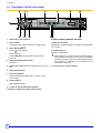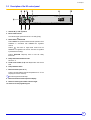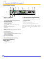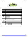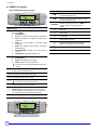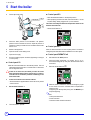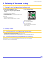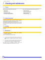
1
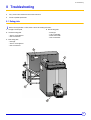
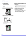
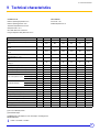
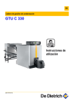
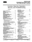
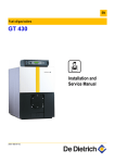
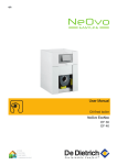
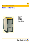
EN Oil-fired condensing boiler GTU C 330 C001933-C User Guide 300017846-001-B . Contents 1 Introduction . . . . . . . . . . . . . . . . . . . . . . . . . . . . . . . . . . . . . . . . . . . . . . . . . . . . . . . . . . . . . . . . . . . . . . . . . . . . .3 1.1 1.2 2 Safety instructions and recommendations. . . . . . . . . . . . . . . . . . . . . . . . . . . . . . . . . . . . . . . . . . . . . . . . . . . .4 2.1 2.2 3 Symbols and abbreviations . . . . . . . . . . . . . . . . . . . . . . . . . . . . . . . . . . . . . . . . . . . . . . . . . . . . . . . . . . . . . . . . . . . . . . . . . . . . . . . .3 General. . . . . . . . . . . . . . . . . . . . . . . . . . . . . . . . . . . . . . . . . . . . . . . . . . . . . . . . . . . . . . . . . . . . . . . . . . . . . . . . . . . . . . . . . . . . . . . .3 Safety instructions . . . . . . . . . . . . . . . . . . . . . . . . . . . . . . . . . . . . . . . . . . . . . . . . . . . . . . . . . . . . . . . . . . . . . . . . . . . . . . . . . . . . . . .4 Recommendations . . . . . . . . . . . . . . . . . . . . . . . . . . . . . . . . . . . . . . . . . . . . . . . . . . . . . . . . . . . . . . . . . . . . . . . . . . . . . . . . . . . . . . .4 Description. . . . . . . . . . . . . . . . . . . . . . . . . . . . . . . . . . . . . . . . . . . . . . . . . . . . . . . . . . . . . . . . . . . . . . . . . . . . . .5 3.1 3.2 3.3 3.4 3.5 General description . . . . . . . . . . . . . . . . . . . . . . . . . . . . . . . . . . . . . . . . . . . . . . . . . . . . . . . . . . . . . . . . . . . . . . . . . . . . . . . . . . . . . .5 Boiler and Condenser. . . . . . . . . . . . . . . . . . . . . . . . . . . . . . . . . . . . . . . . . . . . . . . . . . . . . . . . . . . . . . . . . . . . . . . . . . . . . . . . . . . . .6 Description of the S3 control panel. . . . . . . . . . . . . . . . . . . . . . . . . . . . . . . . . . . . . . . . . . . . . . . . . . . . . . . . . . . . . . . . . . . . . . . . . . .7 Description of the B3 control panel. . . . . . . . . . . . . . . . . . . . . . . . . . . . . . . . . . . . . . . . . . . . . . . . . . . . . . . . . . . . . . . . . . . . . . . . . . .8 Description of the K3 control panel. . . . . . . . . . . . . . . . . . . . . . . . . . . . . . . . . . . . . . . . . . . . . . . . . . . . . . . . . . . . . . . . . . . . . . . . . . .9 4 Changing the settings. . . . . . . . . . . . . . . . . . . . . . . . . . . . . . . . . . . . . . . . . . . . . . . . . . . . . . . . . . . . . . . . . . . .13 5 Start the boiler . . . . . . . . . . . . . . . . . . . . . . . . . . . . . . . . . . . . . . . . . . . . . . . . . . . . . . . . . . . . . . . . . . . . . . . . . .14 6 Arrêter le chauffage. . . . . . . . . . . . . . . . . . . . . . . . . . . . . . . . . . . . . . . . . . . . . . . . . . . . . . . . . . . . . . . . . . . . . .15 6.1 6.2 7 Checking and maintenance . . . . . . . . . . . . . . . . . . . . . . . . . . . . . . . . . . . . . . . . . . . . . . . . . . . . . . . . . . . . . . .16 7.1 7.2 7.3 7.4 8 Checks . . . . . . . . . . . . . . . . . . . . . . . . . . . . . . . . . . . . . . . . . . . . . . . . . . . . . . . . . . . . . . . . . . . . . . . . . . . . . . . . . . . . . . . . . . . . . . .16 Hydraulic pressure . . . . . . . . . . . . . . . . . . . . . . . . . . . . . . . . . . . . . . . . . . . . . . . . . . . . . . . . . . . . . . . . . . . . . . . . . . . . . . . . . . . . . .16 Draining . . . . . . . . . . . . . . . . . . . . . . . . . . . . . . . . . . . . . . . . . . . . . . . . . . . . . . . . . . . . . . . . . . . . . . . . . . . . . . . . . . . . . . . . . . . . . .16 Maintenance . . . . . . . . . . . . . . . . . . . . . . . . . . . . . . . . . . . . . . . . . . . . . . . . . . . . . . . . . . . . . . . . . . . . . . . . . . . . . . . . . . . . . . . . . . .16 Troubleshooting . . . . . . . . . . . . . . . . . . . . . . . . . . . . . . . . . . . . . . . . . . . . . . . . . . . . . . . . . . . . . . . . . . . . . . . .17 8.1 8.2 8.3 9 Stopping the central heating or activating the Summer mode . . . . . . . . . . . . . . . . . . . . . . . . . . . . . . . . . . . . . . . . . . . . . . . . . . . . .15 Prolonged absence. . . . . . . . . . . . . . . . . . . . . . . . . . . . . . . . . . . . . . . . . . . . . . . . . . . . . . . . . . . . . . . . . . . . . . . . . . . . . . . . . . . . . .15 Rating plate . . . . . . . . . . . . . . . . . . . . . . . . . . . . . . . . . . . . . . . . . . . . . . . . . . . . . . . . . . . . . . . . . . . . . . . . . . . . . . . . . . . . . . . . . . .17 Error messages . . . . . . . . . . . . . . . . . . . . . . . . . . . . . . . . . . . . . . . . . . . . . . . . . . . . . . . . . . . . . . . . . . . . . . . . . . . . . . . . . . . . . . . .18 Incidents and solutions . . . . . . . . . . . . . . . . . . . . . . . . . . . . . . . . . . . . . . . . . . . . . . . . . . . . . . . . . . . . . . . . . . . . . . . . . . . . . . . . . . .20 Technical characteristics . . . . . . . . . . . . . . . . . . . . . . . . . . . . . . . . . . . . . . . . . . . . . . . . . . . . . . . . . . . . . . . . .21 10 Energy savings . . . . . . . . . . . . . . . . . . . . . . . . . . . . . . . . . . . . . . . . . . . . . . . . . . . . . . . . . . . . . . . . . . . . . . . . .22 2 GTU C 330 24/11/08 - 300017846-001-B 1. Introduction 1 Introduction 1.1 Symbols and abbreviations In these instructions, various markings and pictograms are used to draw your attention to particular information. In so doing, De Dietrich Thermique wishes to safeguard the user's safety, obviate hazards and guarantee correct operation of the boiler. Caution Risk of material damage. Specific information. Reference Danger ZRefer Risk to another manual or other pages in this instruction of a dangerous situation causing serious physical manual. injury. Warning Risk of a dangerous situation causing slight physical ` DHW: Domestic hot water. injury. 1.2 General 1.2.1 Manufacturer's liability De Dietrich Thermique S.A.S manufactures products in compliance with the standard 1. Products are delivered with 1 marking and all documents required. In the interest of customers, De Dietrich Thermique S.A.S are continuously endeavouring to make improvements in product quality. All the specifications stated in this document are therefore subject to change without notice. 1.2.2 ` Incorrect use of the appliance. ` Faulty or insufficient maintenance of the appliance. ` Incorrect installation of the appliance. ` Perform the initial start up and carry out any checks necessary. ` Explain the installation to the user. ` Warn the user of the obligation to check the appliance and maintain it in good working order. ` Give all the instruction manuals to the user. Installer's liability The installer is responsible for the installation and inital start up of the appliance. The installer must respect the following instructions: ` Read and follow the instructions given in the manuals provided with the appliance. ` Carry out installation in compliance with the prevailing legislation and standards. 1.2.3 The liability of De Dietrich Thermique S.A.S as the manufacturer may not be invoked in the following cases: User's liability To guarantee optimum operation of the appliance, the user must respect the following instructions: ` Read and abide by the instructions given in the user manual. ` Call on qualified professionals to carry out installation and initial start up. ` Get your fitter to explain your installation to you. ` Have the required checks and services done. ` Keep the instruction manuals in good condition close to the appliance. 24/11/08 - 300017846-001-B GTU C 330 3 2. Safety instructions and recommendations 2 Safety instructions and recommendations 2.1 Safety instructions For a proper operating of the boiler, follow carefully the instructions. Only qualified professionals are authorised to work on the appliance and the instalation. Incorrect use or unauthorised modifications to the installation or the equipment itself invalidate any right to Do not obstruct the air inlets in the room (even partially). If you smell flue gases 1.Switch the appliance off 2.Open the windows 3.Evacuate the premises 4.Contact a qualified professional claim. condensates in oil-fired condensing boilers are acidic (2The< pH < 3): The installation of a condensates neutralisation system is recommended. Before any work, switch off the mains supply to the appliance. - The temperature of the flue gas conduits may exceed 65°C - The temperature of the radiators may reach 95°C - The temperature of the domestic hot water may reach 65°C 4 Risk of being burnt Depending on the settings of the appliance: Keep to the polarity shown on the terminals: phase (L), neutral (N) and earth . Keep children away from the boiler. Risk of intoxication Risk of damage Do not stock chloride or fluoride compounds close to the appliance. Fire hazard to store inflammable products and materials .Install the appliance in premises sheltered from rain, snow inIt istheforbidden and boiler room or close to the boiler, even temporarily. frost. Do not neglect to service the appliance: Contact a qualified professional or take out a maintenance contract for the annual servicing of the appliance. 2.2 Recommendations • • • • • • 4 Check regularly that the installation contains water and is pressurised. Keep the appliance accessible at all times. Avoid draining the installation. Use only original spare parts. Never remove or cover labels and rating plates affixed to the appliance. Boiler with DIEMATIC-m3 control panel: The appliance should be on Summer or Antrifreeze mode rather than switched off to guarantee the following functions: - Cleaning the pumps - Antifreeze protection - Protection against corrosion on domestic hot water tanks fitted with a titanium anode GTU C 330 24/11/08 - 300017846-001-B 3. Description 3 Description 3.1 General description GTU C 330 boilers are intended for central heating using radiators or underfloor heating. These boilers have the following characteristics: - Production of domestic hot water can be ensured by a separate hot water calorifier. - Hot water condensing boilers, Heating body in cast iron, Condenser Pressurised boiler, Atomisation burner using domestic fuel oil Connecting to a chimney S3, B3, K3 or DIEMATIC-m3 control panel (See below) The boiler, condenser and burner enable the use of all types of oil : - Standard fuel oil - Oil with low sulphur content. Control panel S3 l 30 0 TEST STB 10A C001967 Control panel K3 Control panel DIEMATIC-m3 Control panel B3 24/11/08 - 300017846-001-B GTU C 330 5 3. Description 3.2 Boiler and Condenser 2 5 3 6 4 1 11 7 8 C001936-B 10 5 2 6 4 3 1 11 7 9 8 1 2 3 4 5 6 10 Burner Control panel Heating flow pipe Boiler flue gas system / condenser connection pipe Condenser C001937-B 7 8 9 10 11 Boiler / condenser hydraulic connecting kit Adjustable feet Condensates evacuation pipe Heating return pipe Recycling kit (Option) Condenser safety control box. The box comprises ; - 80°C limiter thermostat - Safety thermostat with manual reset, set to 120 °C. This thermostat monitors the temperature of the combustion products. 6 GTU C 330 24/11/08 - 300017846-001-B 3. Description 3.3 Description of the S3 control panel 7 6 2 1 3 4 5 l 30 0 TEST STB 10A M000484 1. General ON (1) / OFF (0) switch 2. Switch Test-STB Temporary action to test the safety thermostat 3. Boiler thermostats (30 to 90 °C) The boiler thermostat regulates the boiler operating temperature. 4. Boiler thermometer 5. Location for flue gas thermometer (optional) 6. Timed circuit breaker (10 A) with delayed action and manual reset 7. Safety thermostat with manual reset (set to 110 °C) The safety thermostat with manual reset ensures that the boiler operates safely. In the event that there is an abnormal rise in the temperature in the boiler 110° C. Advise your installation engineer. 24/11/08 - 300017846-001-B GTU C 330 7 3. Description 3.4 Description of the B3 control panel When preparing domestic hot water 1. General ON (1) / OFF (0) switch 2. Alarm indicator 11. Electronic thermostat This indicator lights up when the burner is on safety (faulty). Regulating the storage temperature of domestic hot water between 10° C and 80° C. 3. Switch TEST-STB/./% 12. Indicator lights up Position .: DHW + Heating Domestic hot water display Position %: DHW Position TEST-STB: Temporary action to test the safety thermostat 4. Safety thermostat with manual reset Set at 110° C 5. Timed circuit breaker (10 A) with delayed action and manual reset After switching on, the system performs an automatic purge of the accumulator interchanger for one minute by intermittently operating the domestic load pump and the heating pump. This purge sequence is deactivated if the temperature in the accumulator is above 25º C. 13. Location for hour run meter (Option) 6. Pump shutdown switch 7. Electronic thermostat Set the boiler temperature between 30° C and 90° C using manual setting. 8. Indicator lights up Boiler temperature display 9. Location for flue gas thermometer (optional) 10. Switch for selecting the number of burner stages 8 GTU C 330 24/11/08 - 300017846-001-B 3. Description 3.5 Description of the K3 control panel 1. General ON (1) / OFF (0) switch 2. Burner alarm indicator This indicator lights up when the burner is on safety (faulty). 3. Switch AUTO/!/TEST-STB Position AUTO: This position enables automatic operation of the installation in accordance with DIEMATIC-m 3 regulation controls. Position !: The boiler no longer takes orders from the DIEMATIC-m 3 regulation into account. The boiler is regulated by the boiler thermostat(s). Position TEST-STB: Temporary action to test the safety thermostat 4. Safety thermostat with manual reset Set at 110° C 5. Timed circuit breaker (10 A) with delayed action and manual reset 6. Pump shutdown switch 7. Boiler thermostat (30 to 90 °C) A factory-set stop limits the maximum temperature to 75 °C. The stop may be moved if necessary. ZSee "Moving the thermostat stop". 8. Boiler thermometer. Boiler temperature display. 9. Switch for selecting the number of burner stages 10. Connector for the programming tool 24/11/08 - 300017846-001-B GTU C 330 9 3. Description 3.6 Description of the DIEMATIC-m3 control panel Electromechanical components 1. General ON (1) / OFF (0) switch The panel must always be supplied with 230V voltage: 2. Burner alarm indicator - to ensure the anti-grip of the heating pump, - to ensure Titan Active System® operation when a titanium anode is protecting the DHW tank. This indicator lights up when the burner is on safety (faulty). 3. Switch AUTO/!/TEST-STB Use the mode: Position AUTO: Automatic control Position !: Manual control - "summer" to shut down the heating. - "antifreeze" to shut down the boiler if you are to be absent. Position TEST-STB: Temporary action to test the safety thermostat Furthermore, if an interactive remote control (CDI 2) is connected and the 1 switch is in the off 7 position, there will be no display on the CDI 2. 4. Safety thermostat with manual reset Set at 110° C 5. Timed circuit breaker (10 A) with delayed action and manual reset 6. Pump shutdown switch 7. Boiler thermostat (30 to 90 °C) A factory-set stop limits the maximum temperature to 75 °C. The stop may be moved if necessary. ZSee "Moving the thermostat stop". 8. Boiler thermometer. Boiler temperature display. 9. Switch for selecting the number of burner stages 10. Connector for the programming tool 14. "Boiler" heat curve 15. DIEMATIC-m3 regulator 16. Display 10 GTU C 330 24/11/08 - 300017846-001-B 3. Description Display 3 2 1 0 2 4 4 6 8 10 5 12 14 6 16 18 7 20 22 24 SUNDAY bar 8 ABC 11 10 9 1 Text and numerical display 2 Graphic display bar for the programme in circuit A, B or C 3 Light area: Reduced temperature heating period or tank load disabled 4 Dark area: Comfort temperature heating period or tank load enabled 5 Flashing cursor showing the current time 6 Number display (current time, adjusted values, parameters, etc.) 7 Number of the boiler for which the parameters are displayed 8 The arrows flash when setting values can be modified using the + and - keys 9 Circuit operation symbols > Opening the 3-way valve = Closing the 3-way valve : Displayed circuit pump on ABC Name of the circuit displayed 10 Arrows indicating the chosen time programme (P1, P2, P3 or P4) for the circuit displayed, A, B, C, or the activation of the manual summer mode 11 Symbols indicating that the following inputs/outputs are active DHW load pump on # Summer mode (Automatic or Manual) Burner on D D Burner on with 1 stage Y 24/11/08 - 300017846-001-B Burner on with 2 stages GTU C 330 11 3. Description DIEMATIC-m3 regulator • Keys accessible when the flap is closed Adjustment keys %O Enter (per 1/2 hour) the comfort temperature period or tank load enabled (dark area). $P Enter (per 1/2 hour) the reduced temperature period or tank load disabled (light area). STANDARD Adjustment keys MODE Various operating modes can be selected by successively pressing key MODE: ` AUTOMATIQUE + S Return key J Page scrolling I Line scrolling DAY 7/7: Forced operation at permanent Day temperature DAY (Until midnight): Forced operation at temporary Day temperature * Scroll of boilers connected ` NIGHT 7/7: Forced operation at permanent Night temperature # Manual "Summer" shutdown key. The heating is switched off and DHW production is ensured. ` NIGHT (Until midnight): Forced operation at temporary Night temperature K Fitter settings access key ` DAYS ANTIFREEZ: Antifreeze mode for the number of days set M DO NOT USE ` ANTIFREEZ 7/7: Permanent antifreeze mode Restart key for a DHW calorifier load ` AUTOMATIQUE ` ` DHW: Restarts DHW load until midnight After a few seconds, the display disappears but the mode is activated. DHW 7/7: DHW load is forced permanently Display key for the various counters (number of burner start-ups, number of burner operating hours, etc.) Set temperatures Day (Heating / DHW / Pool) 2$ Set temperatures Night (Heating / DHW) 12 $P, resets all of the time programmes. ` ` 2% • Simultaneously pressing the 2 keys, %O and * Access key to the slave boilers (Panel K3) in a cascade If using only one boiler, this key is inactive. ( Setting the gradients for circuits A, B and C ) Setting the parallel offsets DECAL.// DEP.A, DECAL.// DEP.B or DECAL.// DEP.C for the heating curves on circuits A, B or C. If the Day setting for one of the circuits, A, B or C, is above 30°C, you no longer have access parallel offset on this circuit. +/- Adjustment keys Keys accessible when the flap is open GTU C 330 24/11/08 - 300017846-001-B 4. Changing the settings 4 Changing the settings To change the temperature of the heating water or to change the programming: ` Refer to the connection instructions supplied with the control panel. ` Refer to the description of the installation 24/11/08 - 300017846-001-B GTU C 330 13 5. Start the boiler 5 Start the boiler ` Fill the siphon with water, Control panel B3 - Place the boiler thermostat 7 in the required position. - When preparing domestic hot water, Place thermostat 11 on the required setting. Setting 6 (approx 60° C) recommended. This value must always be below the temperature limiter for the domestic hot water load. - Set the On/Off switch to 1. 0 l ` Check the water pressure in the installation. The hydraulic pressure must be a minimum of 0.8 bars. Adjust the pressure if necessary, avoiding a sudden influx of cold water into the boiler when it is hot. C001965 t TEST STB Control panel K3 Place the boiler thermostat 7 in the required position. The boiler is managed by the boiler fitted with the DIEMATIC-m3 control panel. ` Switch on the appliance ` Open the valves on the heating circuit ` Open the fuel supply Control panel DIEMATIC-m3 ` Provoke a heating request: see below (depending on the type of control panel) ` Set switch 3 to the AUTO position. ` Check that safety thermostat 4 is properly set. To do so, unscrew the hexagonal cap and press the reset button with a screwdriver. ` Set main On/Off switch 1 to 8. Control panel S3 `Set the boiler thermostats 3 to the desired position. The 2nd stage thermostat must be set to a value at least 5°C lower than the 1st stage thermostat. If there is no control unit, we advise you never to set the boiler thermostat below mark 4 (approx. 40°C) in order to avoid the risk of combustion products condensing on the walls of the boiler. Control unit in boiler room electrical cabinet: - See the instructions supplied with the control unit and any remote control unit used. ` l t TEST STB Set the On/Off switch to 1. - Control panel instructions - Burner instructions - Domestic hot water calorifier instructions l 14 C001965 t ` When the boiler is switched on, the tank exchanger is purged for one minute if a tank is connected and its temperature is lower than 25°C. If disgassing has already taken place, press the MODE key to suspend disgassing. ZSee: 0 TEST STB C001965 ` 0 The boiler starts to operate. GTU C 330 24/11/08 - 300017846-001-B 6. Switching off the central heating 6 Switching off the central heating 6.1 Stopping the central heating or activating the Summer mode Control panels DIEMATIC-m3 and K3: The panel must always be supplied with 230V voltage: Control panels S3 and B3 - to ensure the anti-grip of the heating pump, - to ensure Titan Active System® operation when a titanium anode is protecting the DHW tank. 0 l t Use the mode: - "summer" to shut down the heating. - "antifreeze" to shut down the boiler if you are to be absent. TEST STB C001965 1. Set the On/Off switch to O. ZSee: Control panel instructions ZSee: Burner instructions 2. Switch off the boiler electrical power supply 3. Close the fuel supply. 6.2 Prolonged absence 6.2.1 • • • Precautions required in the case of long boiler stops (one or more years) The boiler and the chimney must be swept carefully. Close all the doors of the boiler to prevent air from circulating inside the boiler. We advise removing the pipe which connects the boiler to the chimney and to close off the nozzle with a cover. 6.2.2 Precautions required if the heating is stopped when there is a risk of freezing We recommend the use of a correctly dosed antifreeze agent to prevent to the heating circuit from freezing. If this cannot be done, drain the system completely. 24/11/08 - 300017846-001-B GTU C 330 15 7. Checking and maintenance 7 Checking and maintenance 7.1 Checks Make the following checks at least 1 time a year: Carry out the following maintenance at least 1 time a year: - - Safety devices System pressure Checking burner safety Checking the safety thermostat Condensates neutralisation system Cleaning the burner Cleaning of the heating body Cleaning of the condenser Cleaning the siphon Cleaning the flue gas circuit 7.2 Hydraulic pressure Checking the hydraulic pressure. The hydraulic pressure must be a minimum of 0.8 bars. Adjust the pressure if necessary, avoiding a sudden influx of cold water into the boiler when it is hot. This operation should be required only a few times in each heating season, with very low quantities of water; otherwise, look for the leak and repair it. 7.3 Draining We advise you against draining the system unless it is absolutely necessary. 7.4 Maintenance The boiler will only operate efficiently if the exchange surfaces are kept clean. Have the required checks and services done. ` The boiler must be serviced and fully cleaned and the flue gas conduit swept by a qualified professional at least 1 times per year. ` The condenser and the condensates neutralisation station must serviced at least once a year by a qualified professional. The siphon and the condensates evacuation conduit must imperatively be checked and cleaned at least once a year. 16 GTU C 330 24/11/08 - 300017846-001-B 8. Troubleshooting 8 Troubleshooting ` Carry out the checks mentioned in the burner instructions. ` Contact a qualified professional 8.1 Rating plate Before informing the fitter of a fault, make a note of the following information: 1. The type of control panel, 4. Burner rating plate: 2. Condenser rating plate: - - Serial no. of the appliance - Date of manufacture Burner type Type of combustible Burner serial number Date of manufacture 3. Boiler rating plate: - Boiler type - Serial no. of the appliance - Date of manufacture C001966 2 1 3 4 24/11/08 - 300017846-001-B GTU C 330 17 8. Troubleshooting 8.2 Error messages 8.2.1 Control panel B3 In the event of a fault, the display may show the following messages: Message Faults Action AL 50 Boiler sensor The sensor circuit has been broken or The installation is stopped. short circuited. Advise the installer. AL 52 Domestic hot water sensor The sensor is cut The titanium anode is on an open circuit or the tank is empty. AL td Titanium anode AL tc 8.2.2 Probable causes A short circuit has occurred on the titanium anode or connection reversed. The installation continues to operate but domestic hot water heating is no longer covered. Advise the installer. Production of domestic hot water is stopped. This may be reactivated for 24 hours by disconnecting and reconnecting the power supply to the boiler. Advise the installer. Control panel K3 No error messages displayed. See DIEMATIC-m3 control panel display. 18 GTU C 330 24/11/08 - 300017846-001-B 8. Troubleshooting 8.2.3 Control panel DIEMATIC-m3 Message SHOW REM. CTRL REVISION DISGAS AUX1.SENS.FAIL AUX2.SENS.FAIL UNIV.SENS.FAIL DHW 2 S. FAIL Probable causes Action The message SHOW REM.CTRL indicates the presence of an override on a remote control. To cancel the overrides on all remote controls, press the AUTO key for 5 seconds. Boiler service required. Advise the installer. When connecting voltage, if the hot water tank temperature is below 25 ºC, the boiler carries out a Wait 1 minute. domestic water exchanger purge cycle. The sensor circuit has been broken or short circuited. Advise the installer. The sensor circuit has been broken or short circuited. If the boiler sensor fails, the burner is controlled by the boiler thermostat and the heating and DHW circuits operate normally. Advise the installer. OUTSI. S.FAIL. The sensor circuit has been broken or short circuited. The boiler setting is equal to BOILER MAX. but can be limited by the boiler thermostat to a lower value. - The valve setting is no longer ensured but monitoring the maximum temperature of the circuit after the valve is ensured. - Valves may be manually operated. - Reheating the domestic hot water remains ensured. Advise the installer. DHW S. FAILURE The sensor circuit has been broken or short circuited. BOILER S.FAIL. To ensure domestic hot water production, set the switch AUTO/!/TESTSTB to !. Advise the installer. OUTL S.A FAIL. OUTL S.B FAIL. OUTL S.C FAIL. The sensor circuit has been broken or short circuited. The circuit concerned goes from automatic to manual mode: The pump operates. Advise the installer. ROOM S.A FAIL. ROOM S.B FAIL. ROOM S.C FAIL. The sensor circuit has been broken or short circuited. The circuit concerned operates without any influence from the room sensor. Advise the installer. SMOKE S. FAIL. The sensor circuit has been broken or short circuited. This failure has no impact on the operating modes. Advise the installer. SWIM.P.A S.FAIL SWIM.P.B. S.FAIL SWIM.P.C. S.FAIL The sensor circuit has been broken or short circuited. Pool reheating is independent of its temperature. Advise the installer. SOLAR S. FAIL The sensor circuit has been broken or short circuited. Reheating domestic hot water using the solar panel is no longer ensured. Advise the installer. ST.TANK S.FAIL The sensor circuit has been broken or short circuited. The hot water storage tank reheating operation is no longer assured. Advise the installer. TA-S SHORT-CIR Domestic hot water production is shut down and can be restarted using key . The tank is no longer protected. The Titan Active System® is short-circuited. Advise the installer. TA-S DISCONNEC The Titan Active System® is on an open circuit. Domestic hot water production is shut down and can be restarted using key . The tank is no longer protected. Advise the installer. TA-S FAILURE 24/11/08 - 300017846-001-B Internal problem. Switch off the current. Advise the installer. GTU C 330 19 8. Troubleshooting 8.3 Incidents and solutions The burner is not working: The burner is operating but the radiators are cold: ` Check the boiler thermostat settings. ` Bleed the radiators. ` Carry out the checks mentioned in the burner instructions. ` ` Shutdown by the safety thermostat due to accidental overheating: Checking the hydraulic pressure. The hydraulic pressure must be a minimum of 0.8 bars. Adjust the pressure if necessary, avoiding a sudden influx of cold water into the boiler when it is hot. If it is often necessary to top up the installation with water, contact your fitter. ` Check that the heating pumps are working correctly ` Check the position of the 3 position switch. Control panel B3: TEST-STB/./% on .. Control panel DIEMATIC-m3: AUTO/!/TEST STB on AUTO. Control panel K3: AUTO/!/TEST STB on AUTO ` Check the settings on the boiler thermostat(s). • Boiler: Check that the safety thermostat has not triggered. To restart the boiler, reset the safety thermostat. Remove the safety thermostat hood and press the reset button with a screwdriver. C001951 • Condenser: Check that the safety thermostat has not triggered: - Unscrew the protection cap - Press the resetting button of the burner 1 2 ` Carry out the start-up operations again. Call your fitter. ` Check the circuit breaker 20 GTU C 330 24/11/08 - 300017846-001-B 9. Technical characteristics 9 Technical characteristics Conditions of use: Test conditions: Maximum operating temperature: 90 °C CO² Fuel oil = 13% Maximum operating pressure: 4 bar Ambient temperature: 20 °C Thermostat adjustable from 30 to 90°C Safety thermostat: 110 °C 80°C limiter thermostat - Condenser Flue gas temperature safety thermostat: 120 °C Boiler Nominal output Pn GTU C by 50/30°C PCI efficiency - 100 % Pn - Average temperature: 70 °C PCI efficiency - 30 % Pn - Return temperature: 50 °C PCI efficiency - 30 % Pn - Return temperature: 30 °C Nominal water flow (Nominal output) - ∆T = 20K 334 335 336 337 338 339 kW 93.4 120.3 157.3 192.7 239.7 291.2 % 97.8 96.9 96.4 98.1 97.7 97.6 % 101.5 101.4 101.1 102.2 101.8 101.5 % 103.0 102.8 103.0 104.7 104.0 103.8 4.019 5.178 6.769 8.293 10.312 12.530 m3/h Stand-by losses (1) , ∆T = 30K W 315 335 350 495 500 510 Losses through the outer casing (2) % 69 73 78 83 87 93 W 325 435 650 625 625 1100 Useful output range Auxiliary electrical power (3) by 50/30°C kW 56.7-93.4 93.7-120.3 120.2-157.3 155.4-192.7 191.7-239.7 238.4-291.2 Useful output range by 80/60°C kW 55-90 90-115 115-150 150-185 185-230 230-280 113 133 153 177 197 217 Water content Loss of load hydraulic circuit Combustion chamber l ∆T = 10K (1) mbar 11 18 31 46 68 105 ∆T = 15K (1) mbar 4.6 7.4 14.2 19.5 30.1 46 ∆T = 20K (1) mbar 2.6 4.2 8.0 11 17 26 Inscribed diameter mm 377 377 377 377 377 377 Length mm 613 718 854 993 1117 1245 0.096 0.122 0.148 0.174 0.200 0.226 Volume m 3 Number of sections 4 5 6 7 8 9 Number of baffle plates 6 10 10 10 12 12 Kg/h 149 191 248 306 381 463 °C 50 55 61 62 63 65 Mass flue gas flow rate (3) - by 50/30°C Flue gas temperature (3) Pressure available at the flue gas nozzle mbar 1.0 0.6 1.8 1.9 1.6 1.7 Loss of load flue gas side mbar 0.45 0.8 1.0 1.3 1.6 2.3 Maintenance consumption (4) ∆ T = 30K % Burner type Weight (empty) kg 0.38 0.32 0.25 0.28 0.23 0.19 M202-2S M302-1S M302-3S M302-3S M302-4S M302-5S 678 802 912 1117 1239 1366 (1) Stand-by losses, according to the standard EN 304 (2) as a % of stand-by losses (3) At nominal output (4) Maintenance consumption, as a % of the input - according to the standard EN15034 1 mbar = 10 mmCE = 10 daPa. 24/11/08 - 300017846-001-B GTU C 330 21 10. Energy savings 10 Energy savings Here are a few tips for saving energy: - Install reflector panels behind the radiators. - Do not cover the radiators. Do not hang curtains in front of the radiators. - Insulate pipes to prevent thermal losses and condensation. - Do not obstruct aeration grates (even partially). They help to reduce humidity in the home. The more humid a home, the more heating it consumes. - Turn heating off when airing a room (5 minutes a day is sufficient) Avoid deregulating the thermostat. Place the start/stop switch on Off. - Do not shut down heating completely if you are absent. Lower the thermostat by 3-4°C. - Use the sun's heat as much as possible. - Take showers rather than baths. Use a water-saving shower head. 22 GTU C 330 24/11/08 - 300017846-001-B 11. 11 Warranty You have just purchased one of our appliances and we thank you for the trust you have placed in our products. France Please note that your appliance will provide good service for a longer period of time if it is regularly checked and maintained. The preceding dispositions are not exclusive of benefits for the purchaser of the legal guarantee as stated in Civil Code articles 1641 to 1648. Your fitter and our customer support network are at your disposal at all times. Warranty terms Starting from the purchase date shown on the original fitter's invoice, your appliance has a contractual guarantee against any manufacturing defect. The length of the guarantee is mentioned in the price catalogue. The manufacturer is not liable for any improper use of the appliance or failure to maintain or install the unit correctly (the user shall take care to ensure that the system is installed by a qualified fitter). In particular, the manufacturer shall not be held responsible for any damage, loss or injury caused by installations which do not comply with the following: - applicable local laws and regulations - specific requirements relating to the installation, such as national and/or local regulations - the manufacturer's instructions, in particular those relating to the regular maintenance of the unit - the rules of the profession Belgium The preceding dispositions about the contractual guarantee are not exclusive of profit if the need arises for the purchaser in Belgium of the applicable legal dispositions on hidden defects. Switzerland The application of the warranty is subject to the terms and conditions of sale, delivery and warranty of the company marketing our products. Poland Warranty conditions are included in the warranty card. Other countries The above provisions do not restrict the benefit of the legal laws regarding hidden defects applicable in the buyer's country. The warranty is limited to the exchange or repair of such parts as have been recognised to be faulty by our technical department and does not cover labour, travel and carriage costs. The warranty shall not apply to the replacement or repair of parts damaged by normal wear and tear, negligence, repairs by unqualified parties, faulty or insufficient monitoring and maintenance, faulty power supply or the use of unsuitable fuel. Sub-assemblies such as motors, pumps, electric valves etc. are guaranteed only if they have never been dismantled. 24/11/08 - 300017846-001-B GTU C 330 23 DE DIETRICH THERMIQUE S.A.S. www.dedietrich-thermique.fr FR Direction des Ventes France 57, rue de la Gare F- 67580 MERTZWILLER +33 (0)3 88 80 27 00 +33 (0)3 88 80 27 99 NEUBERG S.A. www.dedietrich-heating.com DE DIETRICH REMEHA GmbH www.dedietrich-remeha.de DE Rheiner Strasse 151 D- 48282 EMSDETTEN +49 (0)25 72 / 23-5 +49 (0)25 72 / 23-102 [email protected] LU VAN MARCKE www.vanmarcke.be BE Weggevoerdenlaan 5 B- 8500 KORTRIJK +32 (0)56/23 75 11 RU DE DIETRICH www.dedietrich-heating.com CN DE DIETRICH www.dedietrich-otoplenie.ru Россия 109044 г. Москва ул. Крутицкий Вал, д. 3 корп. 2, оф. 35 +7 495 988-43-04 +7 495 988-43-04 [email protected] ÖAG AG www.oeag.at AT Schemmerlstrasse 66-70 A-1110 WIEN +43 (0)50406 - 61624 +43 (0)50406 - 61569 [email protected] WALTER MEIER (Klima Schweiz) AG www.waltermeier.com WALTER MEIER (Climat Suisse) SA www.waltermeier.com Bahnstrasse 24 CH-8603 SCHWERZENBACH +41 (0) 44 806 44 24 Serviceline +41 (0)8 00 846 846 +41 (0) 44 806 44 25 [email protected] Z.I. de la Veyre B, St-Légier CH-1800 VEVEY 1 +41 (0) 21 943 02 22 Serviceline +41 (0)8 00 846 846 +41 (0) 21 943 02 33 [email protected] AD001NU-AB CH Room 512, Tower A, Kelun Building 12A Guanghua Rd, Chaoyang District C-100020 BEIJING +86 (0)106.581.4017 +86 (0)106.581.4018 +86 (0)106.581.7056 +86 (0)106.581.4019 [email protected] 39 rue Jacques Stas L- 2010 LUXEMBOURG +352 (0)2 401 401 © Copyright All technical and technological information contained in these technical instructions, as well as any drawings and technical descriptions supplied, remain our property and shall not be multiplied without our prior consent in writing. Subject to alterations. 24/11/08 DE DIETRICH THERMIQUE 57, rue de la Gare F- 67580 MERTZWILLER - BP 30