1
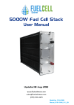
3000W Fuel Cell Stack
User Manual
Updated 15 May 2013
Model No.: FCS-C3000
Manual_H-3000_V1.1_EN
Disclaimer
This manual incorporates safety guidelines and recommendations. However, it is not intended to
cover all situations. It is the responsibility of the customer to meet all local safety requirements and
to ensure safety during operation, maintenance and storage of the H-3000 stack.
Although all efforts have been made to ensure the accuracy and completeness of the information
contained in this document, Horizon reserves the right to change the information at any time and
assumes no liability for its accuracy.
Actions that will void the fuel cell and controller warranty:
●
●
●
●
●
●
●
Attempt,underanycircumstance,todisassembleorinappropriatelytamperwith the fuel cell.
OperatethefuelcellwithacontrollernotdesignedandbuiltbyHorizonforthe speciicfuelcell.
Operatethefuelcellwithvalvesandblowers,thatarenotprovidedbyHorizonfor
thespeciiedfuelcellandcontroller.
Disassemblethefuelcell.
Disassemblethecontroller.
Operatingthefuelcellandcontrollerthatisnotinthesetupand/orspeciiedinthe
usermanualprovideforthespeciicproduct.
OperatethefuelcellstackwithoutthecontrollerproducedbyHorizonorwiththe
controller not produced by Horizon.
Do not attempt, under any circumstance, to disassemble or
inappropriately tamper with the fuel cell. There will be no returns,
refunds or exchanges should disassembly or tampering occur. If
you have questions or need help with regards to the fuel cell and its
technology contact: [email protected]
IMPORTANT
In order for the warranty to come into effect the stack must be registered on the Horizon
Warranty Page at: www.horizonfuelcell.com/warranty.htm
Manual_H-3000_V1.1_EN
Table of Contents
1. Safety..............................................................................................
1
2. Terminology.......................................................................................
6
3. Stack and System Component Information......................................
9
4.TechnicalSpeciications...................................................................
11
5. System Set Up..................................................................................
12
6. Notes for the Set Up .......................................................................... 17
7.SystemSetupDiagram....................................................................
19
8. Polarization Curves...........................................................................
20
9.OperatingInstructions......................................................................... 21
10. Storage and Re-use.......................................................................... 23
11. Troubleshooting................................................................................ 24
12.FuelCellDrawing.............................................................................. 25
13. FAQ.................................................................................................... 26
Manual_H-3000_V1.1_EN
1. Safety
Please read all instructions carefully prior to product use and keep this manual for future reference.
The safety guidelines included here may not cover every situation. Use common sense.
1.1 General information
For this unit to generate electrical power, a supply of hydrogen fuel is necessary. It is important
for any operator to be aware of, understand, and follow all local safety requirements related to the
handling of hydrogen and compressed gases. Ensure that your facility conforms to all local regulatory
requirements, including building codes and recommendations.
The fuel cell system has built-in safeguards and is designed to shut down automatically if any outof-range operating condition occurs. Possible situations include low cell voltage, high current, high
temperature, low fuel pressure.
•Donotoperatethestackonagradeofmorethan65℃.
•Donotconnectordisconnectpowercableswhenthefuelcellstackisenergised.
•Donotdismantlethesystem.ContactHorizonifyouhaveanyconcernsaboutoperation.
1.2 Using Hydrogen
WARNING!FIREOREXPLOSION
Keep all sources of ignition away from hydrogen.
Thisunituseshydrogenfuel.Hydrogenisacolourless,odourlessandlammablesubstance.Itis
highlycombustibleinthepresenceofoxygenandburnswithacolourlesslame.
Leakinggasmaybehotandposeaburndanger.Stopthelowofgas–ifyouarenotindanger–
andusewatertocoolthearea.Ifireoccurs,donotattempttoextinguishlames,allowtheireto
burn out.
Prevent overexposure to hydrogen. Hydrogen is non-toxic but can act as a simple asphyxiant by
displacing the oxygen in the air. There are no warnings before unconsciousness results. When
operating the stack in an enclosure:
•Ensureventilationslotsareclearandunobstructedatalltimesduringoperation.
•Operatewithinthetemperatureslimitsstatedinthemanual.
•Neveroperateifanalarmconditionexists.
Note: We highly recommend customer use a hydrogen sensor(not provided) to detect the
hydrogen leakage.
Manual_H-3000_V1.1_EN
1
1.3 Handling Compressed Gas Cylinders
WARNING
Donothandlecompressedhydrogengascylinderswithouttrainingorexperience.
•Useapressureregulatortocontrolthefuelinletpressuretothesystem.
•Donotaltertheittingonaregulator.Askexperiencedpersonnelforhelp.
•Donotattempttoforcegascylinderthreads.
•Nevertransportagascylinderwithregulatorsattached.Ensurecylindercapsareinplace.Always
use a cylinder cart with a safety strap or chain.
•Secureahigh-pressurecylindertoabench,post,orixedobjecttoavoidaccidentalcontact.
•AvoidunnecessarycontactwithOn/Offvalves.Theycaneasilymoveto“On”byaccident.
1.4HydrogenLeakage
Hydrogen is colourless, odourless and tasteless. Hydrogen is non-toxic but can act as a simple
asphyxiant by displacing the oxygen in the air. There are no warning symptoms before unconsciousness
results.
WARNING
Inhaling hydrogen can lead to unconsciousness and asphyxiation. Hydrogen molecules are smaller
thananyothergas,makinghydrogenmoredificulttocontain.Itcandiffusethroughmanymaterials
consideredairtight.Fuellines,non-weldedconnections,andnon-metalsealssuchasgaskets,O-rings,
pipe thread compounds and packings present potential leakage or permeation sites. Furthermore,
hydrogen’s small molecule size results in high buoyancy and diffusivity, so leaked hydrogen will rise and
become diluted quickly.
Constant exposure to hydrogen causes hydrogen embrittlement in many materials. The mechanisms
thatcausehydrogenembrittlementeffectsarenotwelldeined.Factorsknowntoinluencetherateand
severity of hydrogen embrittlement include hydrogen concentration, hydrogen pressure, temperature,
hydrogen purity, type of impurity, stress level, stress rate, metal composition, metal tensile strength,
grain size, microstructure and heat treatment history. Moisture content in the hydrogen gas may lead to
metal embrittlement through the acceleration of the formation of fatigue cracks. Hydrogen embrittlement
can lead to leakage or catastrophic failures in metal and non-metallic components.
As a preventative measure, the stack must be operated in a well-ventilated area in order to inhibit
potential hydrogen accumulation.
WARNING!
Always operate the stack in a well-ventilated area and ensure that ventilation slots are unobstructed.
Manual_H-3000_V1.1_EN
2
1.5 Flammability and volatility
Hydrogen is flammable over concentrations of 4 – 75% by volume in air, and is explosive over
concentrationsof15–59%.Asaresult,evensmallleaksofhydrogenhavethepotentialtoburnor
explode.Leakedhydrogencanconcentrateinanenclosedenvironment,therebyincreasingtheriskof
combustion and explosion.
Hydrogenlamesarepaleblueandarealmostinvisibleindaylightduetotheabsenceofsoot.Dueto
its high buoyancy and diffusivity, burning hydrogen rises unlike gasoline, which spreads laterally.
Alammableorexplosivehydrogenmixtureiseasilyignitedbyasparkorevenahotsurface.Theautoignition temperature of hydrogen is 500 °C (932 °F). The energy of a hydrogen gas explosion is 2.4
times that of gasoline or methane for an equal volume. Hydrogen gas explosions are therefore more
destructive and carry further.
WARNING!
Amixtureofhydrogenandairispotentiallylammableandexplosiveandcanbeignitedbyasparkora
hot surface.
As in the presence of any fuel, all sources of ignition, including smoking, are not permitted in the vicinity
of the stack.
WARNING!
Keep all sources of ignition away. Smoking is not permitted in the vicinity of the stack.
1.6OxygenDepletion
Oxygen is a colourless, odourless, non-toxic and tasteless gas. Oxygen is essential for life in
appropriate concentrations.
Ambient air contains up to 21% oxygen. Oxygen levels below 19.5% are biologically inactive and
mayactassimpleasphyxiants.Effectsofoxygendeiciencymayinclude:rapidbreathing,diminished
mental alertness, impaired muscular coordination, faulty judgement, depression of all sensations,
emotional instability, and fatigue. As asphyxiation progresses, nausea, vomiting, prostration, and loss
of consciousness may result, eventually leading to convulsions, coma, and death. At concentrations
below12%,immediateunconsciousnessmayoccurwithnopriorwarningsymptoms.
WARNING!
Lackofoxygencanleadtounconsciousnessandasphyxiation.
As a preventative measure, the stack must be operated in a well-ventilated area in order to compensate
for the oxygen used within the fuel cells.
WARNING!
Always operate the stack in a well-ventilated area.
Manual_H-3000_V1.1_EN
3
1.7 Electrical Safety
WARNING!
Avoidcontactwithanexposedfuelcellstack.Electricalshockcancausepersonalinjuryordeath.
•Donottouchfuelcellplatesoranyelectricalcomponentsatanytime.Arunningfuelcellstackisa
potential electrical hazard that can cause burns or electrical shock.
•Donotwearmetallicjewellery–rings,bracelets,watchbands,ornecklaces–whenyouarecloseto
an exposed fuel cell stack.
•Minimisestaticdischarge.Ifpossible,groundallequipment.
•Minimiseconductivity.Avoidcontactwithsurfacesthatareincontactwithwaterorgases.Donot
operate or store in wet or damp conditions.
•Neverusedamagedextensioncords.
Thestackgeneratesupto72VDC(opencircuitvoltage).Thisvoltagedecreasesascurrentisdrawn
from the stack. The stack produces 43.2V at maximum power. This voltage is exposed at the output
power connections. These low voltages may constitute a shock hazard and can damage electronic
components if shorted. Therefore, do not touch individual fuel cells, cell voltage monitoring equipment
or electrical components.
WARNING!
Do not touch fuel cells, cell voltage monitoring equipment or electrical components. Electronic
components can also be damaged as the result of static discharge. To minimise this, ground all
equipment in contact with the stack. Never use damaged extension cords. Minimise conductivity by
avoidingsurfacesincontactwithwater;handsandclothesmustbedry.Donotoperateorstorethe
stack in wet or damp conditions.
WARNING!
Minimise static discharge. Ground all equipment. Residual reactants within the stack can develop a
charge in a matter of minutes when turned off. A reading of zero volts across the entire stack does not
guarantee that all fuel cells are uncharged.
WARNING!
Always assume that the fuel cell stack is charged. Jewellery (such as rings, necklaces, bracelets and
watches) may concentrate an electric current when it comes into contact with charged components,
orwhenashockpassesthroughthehumanbody.Accordingly,nojewelleryshouldbewornnearthe
stack.
WARNING!
Donotwearjewellerynearthestack.
No pungent odor, paint and perfume are allowed around stack.
Manual_H-3000_V1.1_EN
4
1.8 High Temperature
The fuel cell stack is designed to operate at 65ºC. At this operating temperature, the air exhaust stream
temperature can reach 55ºC and the cooling air stream can reach 17ºC above ambient conditions. These
temperaturesaresuficienttocauseburnsorseverediscomfort.Accordingly,avoidcontactwiththefuel
cell stack, or components that convey process or cooling air.
WARNING!
Avoid contact with the fuel cell stack or components that convey process or cooling air.
Manual_H-3000_V1.1_EN
5
2. Terminology
PEM fuel cell:
A PEM (Proton Exchange Membrane) fuel cell is a device that converts hydrogen and oxygen into
water and electricity.
Reactants:
Reactant is a material used to start a chemical reaction. In the fuel cell the reactants are air and
hydrogen by which the electricity will be generated.
Humidiication:
Humidity that the fuel cells need for running.
Blower:
Supply air to the fuel cells and meanwhile decrease the temperature in the stack.
Purgingvalve:
Purges out the water and air gas redundant in the fuel cells.
Mass low per minute:
The total amount of the hydrogen flow through the fuel cell every minute, which the hydrogen
supply can be calculated.
HFCT:
Horizon Fuel Cell Technologies
Manual_H-3000_V1.1_EN
6
A
B
C
D
E
F
G
A: Blowers
B: Hydrogen Inlet connector
C: Fuel cell connect plug
D: Hydrogen supply valve
E: Blower connector
F: Hydrogen purge valve
G: Hydrogen outlet connector
Manual_H-3000_V1.0_EN
7
A
B
C
G
K
I
E
H
J
D
F
A: ON/OFF button
B: SCU(short circuit units) switch
C: LCD connector
D: Fuel cell connect plug
E: Blower power plug
F: Blower signal plug
G: Controller power supply DC 24V+ and DC 24vH: Connect to Load+
I: Connect to FC+
J: Connect to FCK: 232 connector
Manual_H-3000_V1.1_EN
8
3. Stack and System Component Information
1. Stack
Is made up of plate-like cells with air channels to allow
the flow of air across the membrane. The membrane
facilitates the flow of Hydrogen creating the release
of electrons. Electrically conductive separator plates
between each pair of cells enable the flow of electrons.
The stack aspect is that they are all placed on top of each
other and held together by epoxy endplates.
2. H2 Supply and purging valves
The supply valve controls the H2 input. When the
controller turns on, also the H2 supply valve does. When
system turns off, it is in the off position for preventing
hydrogen leakage.
The purging valve purges out the water and air gas
redundant in the fuel cells.
3. Short Circuit Unit
The short circuit unit can be turned on or off depending
on what application the stack is to be used in. When the
short circuit unit turns on, it can enhance performance of
the stack in applications where the stack is turned off for
prolonged periods.
4. On/Off Switch
It is the switch of the controller. Hold it for 2 seconds for
either on or off.
5. Blowers
Supply air to the fuel cells and meanwhile decrease the
temperature in the stack.
6. LCD
Show the Current and Voltage of the stack.
Manual_H-3000_V1.1_EN
9
7. Controller
It controls the stack temperature, blowers, hydrogen input,
purging and short circuiting of the stack.
8. Hydrogen Output
Hydrogen output: connect the tube shown in 11 below.
9. Hydrogen Input
Hydrogen input: connect the tube shown in 11 below with
the hydrogen pressure between 0.45-0.55Bar.
10. Fuel cell +/Fuel cell-&Load- Connectors
FC+ of the controller is connected to the fuel cell positive
pole.
FC- of the controller is connected to the fuel cell negative
pole.
11. Tube for H2 Input and Output
The H2 input tube is connected to the H2 IN as in 9 above
and to the input valve of the hydrogen source. H2 output
tube is connected to the purging valve on one end and the
H2OUTtheother.
12. Grounding cable
Make stack grounded (It was already connected on the
stack when provided).
13 . Fittings
For connecting the load.
Manual_H-3000_V1.1_EN
10
4. Technical Speciications
Control electronics included:
Type of fuel cell
Number of cells
Rated Power
Performance
H2 Supply valve voltage
Purging valve voltage
Blower voltage
Reactants
External temperature
Max stack temperature
H2 Pressure
Hydrogen purity
Humidification
Cooling
Weight (with fan & casing)
Controller
Dimension
Flow rate at max output*
Start up time
Efficiency of stack
Low voltage shut down
Over current shut down
Over temperature shut down
External power supply**
PEM
72
3000W
43.2V @ 70A
12V
12V
12V
Hydrogen and Air
5 to 30ºC
65ºC
0.45-0.55bar
≧99.995﹪ dry H2
self-humidified
Air (integrated cooling fan)
15Kg (±200g)
2.5Kg (±100g)
41.8cm x35cm x 18.3cm
39 L/min
≦30S at ambient temperature
40% @ 43.2V
36V
90A
65℃
13V(±1V), 5A~8A
* The low rate may change with the power output
** System electronics need external power supply
*** The Speciication is subject to change without notice.
Manual_H-3000_V1.1_EN
11
5.
System Set-Up
PLEASE READ CAREFULLY BEFORE STARTING
WARNINGS:
1. The tube between the hydrogen pressure regulator and the fuel cell gas input is required to be less than 30cm.
The inner diameter of the hydrogen supply tube is required to be more than 3mm. The input pressure to the stack is
required to be 0.45-0.55Bar .
2. Disconnect the hydrogen tube from the hydrogen inlets immediately after the fuel cell stack is shut down. Since
hydrogen gas can leak into the fuel cell and destroy the stack.
3. The stack must be standing on the clear plastic feet.
4. Make sure the dry Hydrogen gas to be used must be ≥99.995% purity.
5. Make sure you have purged the water out of the stack as much as possible if you injected water into the stack.
Using the fuel cell stack with too much water inside can irreparably damage it!
6. Do not vibrate the stack when it is in operation.
7. Keep the stack in ventilation when it is in operation.
8. The external power voltage is required to be 12-14V.
9. Keep the SCU always on. Only when it causes your load operating in dificulty, turn off the SCU.
10. The tube between stack output and purging valve is required to be less than 20cm. The tube connected to the
purging valve output is required to be less than 30cm. The inner diameter of the tube is required to be more than
2mm.
STEP 1:
Connect the connectors of the controller and the stack (1A, 1B), to get the blower, the temperature
sensor,thehydrogensupplyvalveandthepurgevalveundercontrol.Theinishedconnectionis
shown in 1C.
1B
1A
1
2
2
3
43
4
5
5
6
7
86
Controller connector
Wire colours
Connector pin #
Blue
#1 & #4
Yellow
#2 & #5
Red
#3 & #6
11
7
Periferals controlled
Hydrogen purge valve
Hydrogen supply valve
Temperature Sensor
12
8
Blowers power connector
Wire colours
Connector pin #
red
Black
#7
#8
Periferals
controlled
Blowers power
1C
Manual_H-3000_V1.1_EN
12
STEP 2:
Connectcontroller"FC+"tothestack"FC+"andcontroller"FC-"tostack"FC-&Load-".Theinished
connectionisshownin2D.ThegroundingcableisalsoconnectedtotheFC-&Load-".
2A
2B
2C
2D
STEP 3:
Connectthecontrollertoastable power supplythroughthe“DC13V”connectors(3A),andthe
voltage of the power supply should be between 12V to 14V.
STEP 4:
KeeptheSCU(ShortCircuitUnit)switchONat“-”forusualuse.
Warning: Some home appliances may not be suitable for this activation process. It may cause
damaging. you can shut off the short circuit by switching it to "O", but it will cause at least 20%
performance loss.
3A
Manual_H-3000_V1.1_EN
4A
13
STEP 5:
Connect the Hydrogen supply valve to stack. The Hydrogen supply valve will prevent damage from
the Hydrogen while the stack is off. Notice the direction of the connection of the Hydrogen supply
valve. The letter "IN" refers to the hydrogen input. Theinishedconnectionisshownin5E.
WARNING:
1. The tube between the hydrogen pressure regulator and the fuel cell gas input is required to be less
than 30cm.The inner diameter of this tube must be more than 3mm. The input pressure to the stack must
be 0.45-0.55Bar.
2. Disconnect the hydrogen supply from the hydrogen inlets immediately after the fuel cell stack is shut
down. Since hydrogen gas can leak into the fuel cell and destroy the stack.
5A
5B
5C
5D
5D
5E
Manual_H-3000_V1.1_EN
14
STEP 6:
Connect the stack to the purge valve. The letter "IN" refers to the hydrogen input. Theinished
connectionisshownin6D.Keeptheoutputofthepurgevalvetoaplaceawayfromthestackin
case of the damage caused by purged hydrogen.
6A
6C
6B
6D
Note: The tube between stack output and purging valve is required to be less than 20cm.
The tube connected to the purging valve output is required to be less than 30cm. The inner
diameter of the tube is required to be more than 2mm.
Manual_H-3000_V1.1_EN
15
STEP 7:
Check all the connection first and connect the load to the system, Load+ is connected to the
"load+"atthecontroller,Load-connectedtothe"FC-andload-"inthestackshownin7A.
7A
STEP 8:
Connect LCD to the controller as shown in 8A. Provide hydrogen and turn on external power
supply,thenpresstheON/OFF(8B)switchformorethan2secondstostartthesystem.Ifyouwant
toswitchoffthesystem,presstheON/OFF(8B)switchfor2seconds.
8B
8A
STEP 9: Check the following steps before starting the system:
1.
The connection between hydrogen pressure and hydrogen supply valve.
2.
The connection between hydrogen supply valve and the stack input.
3.
The connection between stack output and purging valve.
4.
The output tube of the purging valve is kept away from the stack.
5.
The pin connections between stack and controller.
6.
The input hydrogen pressure is 0.45-0.55Bar.
7.
The external power supply is 13V(±1V), 5A-8A.
8.
The load is below 3000W.
The System is now setup and ready to be used.
Manual_H-3000_V1.1_EN
16
6. Notes for the set-up
Note: The pictures in this section below are only for reference.
Stack should be placed like this
position. Stand on the plastic feet.
The voltage of external power supply is
between 12V-14V, the current range is
different based on the different stack.
The tube is required to be less than 20cm between stack
output and purging valve. The tube connected to the purging
valve output is required to be less than 30cm. The inner
diameter of the tube is required to be more than 2mm.
Warning: The tube between the hydrogen pressure regulator
and the fuel cell gas input is required to be less than 30cm.
The pressure of the hydrogen is
between 0.45--0.55Bar.
The load connecter, load+, is connected to
the "load +"in the controller. The load- is
connected to "FC- & Load-" in the stack.
Manual_H-3000_V1.1_EN
17
The outlet of the purge valve should be far away from
the stack. Don't let the hydrogen from purge valve low
back to the stack, otherwise it would damage the stack.
Note: The tube between stack output and purging valve is
required to be less than 20cm. The tube connected to the purging
valve output is required to be less than 30cm. The inner diameter
of the tube is required to be more than 2mm.
Manual_H-3000_V1.1_EN
18
7. System setup diagram
SCU: Short Circuit Unit
GND:Grounding
Manual_H-3000_V1.1_EN
19
8. Polarization curves
Performance characteristics of the stack are presented. All performance data is given
forbaselineoperatingconditions,deinedatsea-levelandroomambienttemperature.
V
H3000 U-I Curve
80
70
60
50
40
30
20
10
A
0
0
10
20
30
40
50
60
70
80
90
H3000 U-I Curve
ml
H3000 H2 Flow
45000
40000
35000
30000
25000
20000
15000
10000
5000
W
0
0
500
1000
1500
2000
2500
3000
3500
H3000 H2 Flow
3500
W
H3000 P-I Curve
3000
2500
2000
1500
1000
500
A
0
0
10
20
30
40
50
60
70
80
90
H3000 P-I Curve
Manual_H-3000_V1.1_EN
20
9. Operating instructions
STARTUP PROCEDURE
Make sure both the stack and the ambient temperature are less than 45℃.Otherwisethesystem
will not start up successfully.
HoldtheON/OFFbuttondownfor2secondsandthenreleaseittostartthesystem;youwillhear
one beep, which means the system has started.
RUNNING PROCEDURE
After system has started, depending on your setup and application you can change your load to get
thepoweryouneedwithinthespeciiedpowerrangeforthisfuelcell.
Don’tconnectupaloadthatwilldemandmorepowerthan3000Wwhichcanpermanentlydamage
the fuel cell.
Duringtheoperation,monitortheHydrogenlowandpressuretoconsistentlysupplyhydrogenat
0.45-0.55Bar.
Monitor the external power is providing 12-14V.
Directtheoutlettubingofthepurgevalveawayfromthefuelcell.Donotletthepurgedhydrogen
go back towards the fuel cell stack, it will damage the fuel cell.
Pay attention to the purge, take care of the performance during the purge, If after each purge, the
performanceisincreasedabout10%,itmeansyouneedtoincreasethepressureofhydrogena
smallamount.Thefuelcellisloodingandsoyouneedtousethepressuretopushextrawaterout.
Duringtheoperation,youneedtokeeptheSCUONat"-",itwillconditionthefuelcellforrated
power and keep it conditioned for long performance lifetimes.
●Shortcircuitwillhappenevery10secondsandlastfor100mseverytime.
●Iftheloaddoesnotoperatewellwiththeshortcircuitonwerecommendthatyourunthe
fuel cell for 10 minutes prior to switching the load on.
●Therewillbeaslightdecreaseinthepowerprovidedtotheloadwiththeshortcircuitoff.
Manual_H-3000_V1.1_EN
21
SHUTDOWN PROCEDURE
To shut down the fuel cell system down, please follow these steps:
1. Turn off the load.
2.HoldtheON/OFFbuttondownfor2secondstostopthesystem,youwillhearonelongbeep,
which means the system is shutting down.
Note: When you turn off the on/off switch connected
to the control box at the temperature of the fuel
cell stack higher than 45˚C the stack will not
stop working immediately. Only when the stack
temperature goes down below 45˚C, the whole
system will stop operation in order to protect the
stack. So in order to make it work well, the fuel cell
stack must be maintained lower than 45˚C before
operate the on/off switch.
3. Turn the hydrogen supply off.
4.Disconnectthehydrogensupplytubefromthehydrogeninletsasshowninthepicturebelow.
WARNING:
Disconnect the hydrogen tube from the hydrogen input ports immediately after the fuel cell stack is shut
down. Since hydrogen gas can leak into the fuel cell and destroy the stack.
If the fuel cell is not in use, please follow these inal steps.
Disconnecttheexternalpowersupplyfromthecontroller.
Completely disconnect the fuel cell system from the load.
Completely disconnect the fuel cell system from the controller.
Letthefuelcellcooldownbeforeplacingitintoanairtightcontainer.Thiswillhelptomaintainits
performance particularly during long periods of storage.
Manual_H-3000_V1.1_EN
22
10. Storage and Re-Use
Wheninishedoperatingthestack,placeitinanenclosedareaforstoragetokeepthestackfromgetting
too dry. The stack should be stored at room temperature.
Ifthestackisun-usedforalongperiodoftime(morethan4weeks)andit'sperformancegoesdown50%
to the rated power at 43.2V after 30 minutes operation, we recommend do the following steps.
Note: Generally, injecting water into the stack it is not recommended. Only if the performance of the stack
decreases 50% is it recommended to inject water into the stack to activate the stack before operation.
Rejuvenate by injecting water into the stack (the following pictures are only for reference):
1.
Connectatubetothe“H2input”port.
2.
Fillasyringe(notprovided)withdistilledorpuriiedwater(seepictureA).Makesurethereisnoair
in the syringe. And then connect it to the tube.
3.
Injectdistilledorpuriiedwaterintothestackuntilyouseewatercomingoutofthe“H2output” ports. Keep the water inside the stack for about 2 minutes. Now disconnect
the syringe with the tube.
4.
Purged water out of the stack.
Connect the H2 supply (0.45-0.55Bar) to the stack through the tube without a load attached (see
pictureB),topurgewateroutofthestackasmuchaspossible(i.e.lettinghydrogenlowthrough
the stack to remove water and other contaminants) (see picture C). Using the fuel cell stack with
too much water inside can irreparably damage it!
0.45-0.55Bar
A
B
WARNING:
C
Manual_H-3000_V1.1_EN
1. Make sure the hydrogen supply pressure is
0.45-0.55Bar.
2. Please make sure you have purged the
water out of the stack as much as possible
before use if you injected water into the stack.
Using the fuel cell stack with too much water
inside can irreparably damage it!
3. The tube between the hydrogen pressure
regulator and the fuel cell gas input is required
to be less than 30cm.
23
11. Trouble Shooting
If the stack is not used for a long time (months), it will take a little time to get the rated
power, it needs 5-30 minutes.
Only it's performance goes down 50% to the rated power at 43.2V after 30 minutes operation
we recommend to inject water into the stack to activate the stack before operation. Please
see the detailed information in Storage and Re-Use.
If the system shuts down by itself check the following details:
1.
MakesureyouhaveconnectedallwiresaccordingtotheSystemSetupDiagram.
2.
Make sure the external power supply is 13V(±1V), 5A-8A.
3.
Make sure the input hydrogen pressure is 0.45-0.55Bar.
4.
Make sure the load is below 3000W, because the controller will protect the stack from
drawing too much current.
5.
Check whether the fuel cell temperature is below 65oC, the system will shut off if it is above 65oC.
Do not attempt, under any circumstance, to disassemble or
inappropriately tamper with the fuel cell. There will be no returns,
refunds or exchanges should disassembly or tampering occur. If
you have questions or need help with regards to the fuel cell and its
technology contact: [email protected]
Manual_H-3000_V1.1_EN
24
12. Fuel Cell Drawing
418
183
183
350
135.5
370
Manual_H-3000_V1.1_EN
418
370
350
25
13. FAQ
What is the SCU?
This is the Short Circuit Unit, it helps to condition the fuel cell for long term good performance.
What is the Hydrogen pressure supplied to the fuel cell stack?
The pressure is required to be 0.45-0.55Bar.
What is the maintenance of the stacks?
1.Whenthestackinishesoperation,disconnectthehydrogeninputandoutputtubefromthestack
and also disconnect the power output. Use a tube to connect the hydrogen input to the hydrogen
output of the stack.
2. Store the stack in ambient temperature and in a closed space. Keep it away from toxic gas, such
as So2, H2S, Co.
3.Operatethestackfor2-3hoursevery2weeksoratleastonemonthinordertomaintainthe
stability of the stack performance.
4. If the stack has not been used for more than 2 months, the stack power maybe get a little bit
down when you use it again. We suggest at the beginning not to have full load to the stack, try
tohavehalfpowerforthestarting.Andthenstepbystepincreasetofullload,trytoincrease5%
every 10 minutes. After this activation process, the stack can reach the rated power within 1-2
hours.
5. If the stack has not been used for more than 2 months and your load could be set to constant
voltage,trytooperatethestackunder0.6V/cell.Underthisoperationmode,thestackcanreach
the rated performance within 1-2 hours.
Manual_H-3000_V1.1_EN
26