1
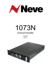
1073 & 1084 Channel Amplifiers
Contents
Introduction
1
High Pass Filter (resistor modification)
1
Important Note
1
Installation
2
Dimensions
3
Power Requirements
3
Mains Supply (rack units)
4
DC Power Supply Indicators (rack units)
4
Phantom Power
4
Output Level Control
4
Connector Details
5
Amplifier Controls
6
1073 Module
6
1084 Module
7
Specifications
1073 and 1084 Modules
Recall Sheets
1073 - Vertical Module
8
8
9
9
1073 - Horizontal Module
10
1084 - Vertical Module
11
1084 - Horizontal Module
12
Service Information
13
Schematic Drawing Index - 1073/1084 Racks
13
Schematic Drawing Index - 1073 Module
13
Schematic Drawing Index - 1084 Module
14
User Guide Issue 5.1
Page i
1073 & 1084 User Manual
AM5028
Introduction
These 45 series modules are the same as the original designs, and contain all of the original
components.
1073 Channel Amplifiers
These very popular sounding mic pre's are considered by many to capture the very essence of the
Neve sound. In manufacture since the early 1970s, the Class A design offers 3 bands of EQ with
one fixed high frequency and a high pass filter.
1084 Channel Amplifiers
Based on the same technology as the 1073s, the 1084s again deliver the unique sound and quality
of Neve. However, the 1084s offer additional features, including 3 switchable EQ bands with cut
and boost, a high Q for presence and low pass/high pass filters.
High Pass Filter (resistor modification)
Important Note
The high pass filter in both the 1073 & 1084 modules is a passive design and as such must be
correctly terminated to achieve a maximally flat response.
In order to achieve this there is a 5k1 resistor fitted inside the module on the back connector
between pin E (0v) and pin K (fader send) see diagram below:
In situations where the fader connection is not used (most Neve 45 series consoles except
BCM10's) then the resistor remains in place.
In situations where the fader connection is used (BCM10's and AMS Neve 1073/1084 racks)
then the 5k1 resistor should be disconnected and replaced with a fader or potentiometer whose
value is 4k7 / 5k ohms.
Failure to do so will result in incorrect levels and uneven frequency response.
User Guide Issue 5.1
Page 1
1073 & 1084 User Manual
AM5028
Installation
The 1073s and 1084s are available as stand-alone modules, or in a choice of two housings.
The 3U rack houses two modules mounted horizontally in a 19” rack-mounting unit.
The 5U rack houses eight modules mounted vertically in a 19” rack-mounting unit.
Both have rear panels with XLRs for transformer balanced I/O.
The 3U rack rear panel has a fused, voltage selector IEC mains input connector. The 5U rack has a
free standing AC supply with a fused, voltage selector IEC mains input connector and connects to
the rack via a connector and a 1.5 meter cable.
Modules of any combination can be fitted into a rack unit.
Additional Information
*Rack Mount Instructions *_
A) Elevated Operating Ambient - If installed in a closed or multi-unit rack assembly, the operating ambient
temperature of the rack environment may be greater than room ambient. Therefore, consideration should
be given to installing the equipment in an environment compatible with the maximum ambient
temperature (Tma) specified by the manufacturer.
B) Reduced Air Flow - Installation of the equipment in a rack should be such that the amount of air flow
required for safe operation of the equipment is not compromised.
C) Mechanical Loading - Mounting of the equipment in the rack should be such that a hazardous
condition is not achieved due to uneven mechanical loading.
D) Circuit Overloading - Consideration should be given to the connection of the equipment to the supply
circuit and the effect that overloading of the circuits might have on overcurrent protection and supply
wiring. Appropriate consideration of equipment nameplate ratings should be used when addressing this
concern.
E) Reliable Earthing - Reliable earthing of rack-mounted equipment should be maintained.
Particular attention should be given to supply connections other than direct connections to the
branch circuit (e.g. use of power strips).
Recommended Tma = 50 deg C
User Guide Issue 5.1
Page 2
1073 & 1084 User Manual
Dimensions
Mains Voltage Adjustment
1.) Switch off unit.
2.)
Remove fuse.
3.) Turn inner barrel with screwdriver or coin until correct voltage figure is under the white
arrow on the housing.
4.) Replace fuse.
Dimensions
Stand-alone Modules
Width
mm (inches)
Height
mm (inches)
Depth
mm (inches)
Approx.
Weight
kg (lbs)
1073 Module
45 (1.8)
222 (8.75)
254 (10)
2.5 (5.5)
1084 Module
45 (1.8)
222 (8.75)
254 (10)
2.5 (5.5)
19" Rack Mounting
U
Depth
mm (inches)
Height
mm (inches)
Approx. Weight
kg (lbs)
2 Module Version
3
405 (16)
133 (5.25)
11 (24.2) *
8 Module Version
5
405 (16)
222 (8.75)
30 (66) *
* Fully populated rack
User Guide Issue 5.1
Page 3
1073 & 1084 User Manual
Power Requirements
Power Requirements
Rack Units
3U
5U
Rated Voltage
100-230V AC
100-230V AC
Rated Frequency
50-60 Hz
50-60Hz
Rated Current
0.5A Max
0.8A Max
Operating Voltage
100-230V AC
100-230V AC
Fuse Rating and Type
T0.5A H 250V
20mm x 5mm CERAMIC
T1A H 250V
20mm x 5mm CERAMIC
Location
IEC Mains connector
IEC Mains connector
Primary Protection Fuse:
Secondary Protection Fuse:
Output Voltage
24V DC
Fuse Rating and Type
T 2.0A L 250V
20mm x 5mm GLASS
Location
F1
Output Voltage
48V DC
Fuse Rating and Type
T 250mA L 250V
20mm x 5mm GLASS
Location
F2
Modules
Power
1073 Module
106mA ±10mA at 24V DC. Negative Earth
1084 Module
106mA ±10mA at 24V DC. Negative Earth
Mains Supply (rack units)
The 3U rack has a fused, voltage selector IEC mains input connector.
The 5U rack has a free standing AC supply with a fused, voltage selector IEC mains input connector
and connects to the rack via a connector and a 1.5 meter cable.
The mains switch on the rear panel of the 3U rack unit is non-illuminating.
The CH (chassis) and 0V are linked internally.
DC Power Supply Indicators (rack units)
The red LED on the front panel of both 3U and 5U rack units indicates +24V power healthy when
illuminated.
The green LED on the front panel of both 3U and 5U rack units indicates +48V power healthy when
illuminated.
User Guide Issue 5.1
Page 4
1073 & 1084 User Manual
Phantom Power
Phantom Power
Phantom power can be supplied to each module by pressing the phantom power switch on the front
panel of the 3U or 5U rack. The LED in the switch will illuminate confirming that phantom power is
supplied.
Output Level Control
Each channel has an independent Output Level Control. The control is post-input, post-EQ and
pre-output. This control can reduce the level at the output.
When the Output Control is fully clockwise the output gain is unity. The output is 20dB down with
the control in the mid-position.
Modules In Transit
Please note that the designs of the AMS Neve classic modules and racks are to the original Neve
specifications and are not designed to withstand transit.
Should you wish to move the rack from one location to another (for example shipping to another
studio location or returning the rack to a repair center for servicing), please remove all installed
modules from the rack and package the rack and each module separately in packaging suitable to
withstand the intended transit.
If modules are installed in a rack while in transit, damage to the internal edge connectors may
occur.
User Guide Issue 5.1
Page 5
1073 & 1084 User Manual
Connector Details
Connector Details
Standalone 1073 & 1084
Module Wiring to 18 way Free Plug
To Pin V
A
Hi
B
Lo
Mic I/P
-20dBu
Line I/P
0dBu
C
D
E
0V
F
Hi
H
Lo
J
To Pin V
K
Link
L
M
N
Technical
Earth Link
0V
P
Unbalanced O/P
R
Hi
BAL O/P
-3dBu
0dBu
Lo
S
T
U
To Pin V
+24V at 106mA
V
User Guide Issue 5.1
Page 6
1073 & 1084 User Manual
Amplifier Controls
Amplifier Controls
1073 Module
dB
LINE
-80
70
-20
60
10
OFF
50
High Frequency:
Smooth +/-16dB fixed frequency shelving at 12kHz.
Low Frequency:
Smooth +/-16dB shelving with selectable frequencies of 35Hz,
60Hz, 110Hz & 220Hz.
Mid Frequency:
Smooth +/-18dB peaking, fixed 'Q' with, selectable centre
frequencies of 0.36kHz, 0.7kHz, 1.6kHz, 3.2kHz, 4.8kHz &
7.2kHz.
High Pass Filter:
18dB per octave slope, switchable between 50Hz, 80Hz,
160Hz & 300Hz.
EQL Button:
Switches the equaliser in or out of circuit.
Phase Button:
Gives 180° Phase change at Balanced Output.
0
40
30
MIC
-20
+10
OFF
-
+
0
-
+
OFF
7.2
4.8
0.36
KHz
3.2
0
1.6
0.7
-
+
OFF
35
Hz
220
0
110
60
OFF
Hz
300
EQL
160
80
PHASE
LINE
-80
70
50
-20
-
+
-
+
10
OFF
50
OFF
7.2
OFF
OFF
0
40
MIC
30
-20
dB
User Guide Issue 5.1
-
+
60
+10
OFF
4.8
0
0.36
3.2
0
1.6
KHz
0.7
35
220
0
110
Hz
60
50
300
160
80
P
H
A
S
E
E
Q
L
Hz
Page 7
1073 & 1084 User Manual
Amplifier Controls
1084 Module
dB
LINE
-80
70
-20
60
10
OFF
50
High Frequency:
Smooth +/-16dB shelving wit selectable frequencies of 10kHz,
12kHz and 16kHz.
Low Frequency:
Smooth +/-16dB shelving with selectable frequencies of 35Hz,
60Hz, 110Hz & 220Hz.
Mid Frequency:
Smooth +/-12dB or +/-18dB peaking with switchable 'High Q',
selectable centre frequencies of 0.36kHz, 0.7kHz, 1.6kHz,
3.2kHz, 4.8kHz & 7.2kHz.
High Pass Filter:
18dB per octave slope, switchable between 45Hz, 70Hz, 160Hz
& 360Hz.
Low Pass Filter:
18dB per octave slope, switchable between 6kHz, 8kHz, 10kHz,
14kHz, & 18kHz.
EQL Button:
Switches the equaliser in or out of circuit.
Phase Button:
Gives 180° Phase change at Balanced Output.
0
+10
OFF
40
30
MIC
-20
-
+
OFF
16
KHz
10
12
Hi-Q
-
+
OFF
7.2
4.8
0.35
KHz
3.2
1.6
0.7
-
+
OFF
35
Hz
220
110
60
6
360
8
160
10
70
Hz
14
45
EQL
OFF
18
PHASE
KHz
Hz
LINE
-80
70
-20
-
+
60
-
+
-
+
10
OFF
OFF
50
0
16
40
MIC
30
-20
dB
User Guide Issue 5.1
+10
OFF
10
KHz
12
Hi 7.2
Q
0.35
3.2
1.6
KHz
0.7
6
14
35 70
220
110
Hz
60
45
P
H
A
S
10 E
8
1
OFF 6
0
OFF
4.8
KHz
360
OFF
E
Q
L
18
Page 8
1073 & 1084 User Manual
Specifications
Specifications
1073 and 1084 Modules
Microphone Input:
Input Impedance 300W or 1200W, gain +80db to +20dB in
5dB steps.
Line Input:
Input Impedance 10,000W bridging, gain +20dB to -10dB in
5dB steps.
Both inputs are transformer balanced and earth free.
Output:
Maximum output is >+26dBu into 600W. Output impedance is
75W @1kHz.
Output is transfomer balanced and earth free.
Distortion:
Not more than 0.07% from 50Hz to 10kHz at +20dBu output
(80kHz bandwidth) into 600W.
Frequency Response:
+/-0.5dB 20Hz to 20kHz, -3dB at 40kHz Eq Out.
Noise:
Not more than -83dBu at all Line gain settings Eq In/Out
(22Hz to 22kHz bandwidth).
EIN better than -125dBu @ 60dB gain.
User Guide Issue 5.1
Page 9
1073 & 1084 User Manual
Recall Sheets
Recall Sheets
1073 - Vertical Module
dB
LINE
-80
70
-20
60
10
OFF
50
0
40
30
MIC
-20
+10
OFF
-
+
0
-
+
OFF
7.2
4.8
0.36
KHz
3.2
0
1.6
0.7
-
+
OFF
35
Hz
220
0
110
60
OFF
50
Hz
300
EQL
User Guide Issue 5.1
160
80
PHASE
Page 10
User Guide Issue 5.1
40
MIC
OFF
50
60
70
30
dB
-80
-20
+10
OFF
0
10
-20
LINE
+
0
-
4.8
7.2
+
3.2
0
1.6
KHz
0.7
0.36
OFF
+
220
0
110
Hz
60
35
OFF
-
300
Hz
160
80
50
OFF
E
Q
L
P
H
A
S
E
1073 & 1084 User Manual
Recall Sheets
1073 - Horizontal Module
Page 11
1073 & 1084 User Manual
Recall Sheets
1084 - Vertical Module
dB
LINE
-80
70
-20
60
10
OFF
50
0
+10
OFF
40
30
MIC
-20
-
+
OFF
16
KHz
10
12
Hi-Q
-
+
OFF
7.2
4.8
0.35
KHz
3.2
1.6
0.7
-
+
OFF
35
Hz
220
110
60
6
360
8
160
10
70
Hz
14
45
EQL
User Guide Issue 5.1
OFF
18
KHz
PHASE
Page 12
User Guide Issue 5.1
40
MIC
OFF
50
60
70
30
dB
-80
-20
+10
OFF
0
10
-20
LINE
+
10
KHz
12
16
OFF
Hi
Q
4.8
7.2
+
3.2
1.6
KHz
0.7
+
0.35
OFF
-
220
110
Hz
60
360
45
35 70
1
OFF 6
0
-
Hz
OFF
18
6
KHz
14
10
8
E
Q
L
P
H
A
S
E
1073 & 1084 User Manual
Recall Sheets
1084 - Horizontal Module
Page 13
1073 & 1084 User Manual
Service Information
Service Information
Schematic Drawing Index - 1073/1084 Racks
3U Horizontal Rack (AM5028)
AM5028 Assembly Drawing
AM5028 Wiring Diagram
5U Vertical Rack (AM5033)
AM5033 Assembly Drawing
AM5033 Wiring Diagram
Schematic Drawing Index - 1073 Module
1073 Channel Amplifier (PL31073-C)
E10006 Block Diagram
EH10023 Circuit Diagram
High Pass Filter (PL10182/C)
PL10182/C Assembly Drawing
D/10019C Circuit Diagram
HF/LF EQ Frequency (PL10205)
PL10205 Assembly Drawing
D/10042 Circuit Diagram
Presence Frequency (PL10211)
BA211 Assembly Drawing
D/10048 Circuit Diagram
Mic Line Output (PL10283AV)
PL10283 Assembly Drawing
EX10283 Circuit Diagram
Mic Amp/EQ Amp (PL10284)
PL10284 Assembly Drawing
EX10284 Circuit Diagram
Sensitivity Switch (PL20033)
EK20033 Wiring Diagram
Low Frequency Switch (PL20065)
EK20065 Wiring Diagram
HP Filter Switch (PL20066)
EK20066 Wiring Diagram
Presence Switch (PL20105)
EK20105 Wiring Diagram
User Guide Issue 5.1
Page 14
1073 & 1084 Channel Amplifiers
Service Information
Schematic Drawing Index - 1084 Module
1084 Channel Amplifier (PL31084-C)
EB20039 Block Diagram
EH10036 Circuit Diagram
High Pass Filter (PL10182/A)
PL10182/A Assembly Drawing
D/10019A Circuit Diagram
Low Pass Filter (PL10194/A)
PL10194/A Assembly Drawing
D10031/A Circuit Diagram
HF/LF EQ Frequency (PL10205)
See 1073 drawing section
Presence Frequency (PL10211/A)
PL10211/A Assembly Drawing
D/10048/A Circuit Diagram
Mic Line Output (PL10283AV)
See 1073 drawing section
Mic Amp/EQ Amp (PL10284)
See 1073 drawing section
Sensitivity Switch (PL20033)
See 1073 drawing section
Low Frequency Switch (PL20065)
See 1073 drawing section
Presence Switch (PL20105)
See 1073 drawing section
High Frequency Switch (PL20106)
EK20106 Wiring Diagram
HP/LP Filter Switch (PL20107)
EK20107 Wiring Diagram
User Guide Issue 5.1
Page 15