1
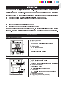
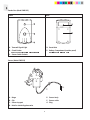
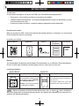
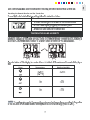
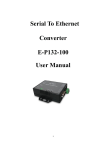
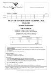
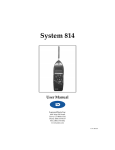
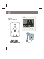
MODEL:
CM113 / CMR113
CENT
HOUR
COM
CHECK
USER
MANUAL
PENCE
CENT
kWh
NE
MODEL CM113/CMR113/CMS113
Wireless Energy Monitor
Patent Pending
USER MANUAL
TABLE OF CONTENTS
TABLE OF CONTENTS ..............................................................................................................................1
INTRODUCTION .........................................................................................................................................3
KEY FEATURES .........................................................................................................................................3
Remote Monitor (Model CM113) ............................................................................................................. 3
Sender Box (Model CMR113) ..................................................................................................................4
Sensor (Model CMS113) ......................................................................................................................... 4
LCD display symbols ...............................................................................................................................5
WARNINGS.................................................................................................................................................6
Warnings ..................................................................................................................................................6
SAFETY AND CARE INSTRUCTIONS.......................................................................................................6
Safety precautions ...................................................................................................................................6
Caring for this product ............................................................................................................................6
HOW THE PRODUCT WORKS ..................................................................................................................7
Overview...................................................................................................................................................7
Volta e and rrent ..................................................................................................................................7
atts and Kilowatts .................................................................................................................................7
Ho se old power able and Ôp aseÕ .......................................................................................................7
Green o se as .......................................................................................................................................7
QUICK INSTALL GUIDE ............................................................................................................................8
GETTING STARTED ................................................................................................................................. 10
Yo will need .......................................................................................................................................... 10
Unpa kin t e Prod t .......................................................................................................................... 10
Batteries ................................................................................................................................................. 10
Loadin t e batteries ............................................................................................................................. 10
AC adapter ...............................................................................................................................................11
W
g
cu
u h
hu g
u
c gh
c
h
uc
gh
Mounting the Remote Monitor .................................................................................................................11
Mounting the Sender Box ........................................................................................................................11
Attaching the Sensor................................................................................................................................12
Plugging the Sensor into the Sender Box................................................................................................12
CUSTOMISING SETTINGS ........................................................................................................................13
Setting the voltage ...................................................................................................................................13
Setting the electricity cost-per-hour.........................................................................................................13
Setting the cost-per-hour currency unit .................................................................................................13
Setting the cost-per-hour value ...............................................................................................................14
Setting the greenhouse gas emissions per kW rate.................................................................................14
Setting the battery power save mode......................................................................................................14
1
MAIN UNIT INFORMATION........................................................................................................................15
To display power consumption in amps...................................................................................................15
SETTING THE ALARM ...............................................................................................................................15
To set the alarm limit ..............................................................................................................................15
Activating the alarm..................................................................................................................................16
USING THE SEARCH AND CHECK FUNCTION ......................................................................................16
Using the search function ........................................................................................................................16
Resetting the Remote Monitor and the Sender Box ................................................................................17
TEMPERATURE AND HUMIDITY..............................................................................................................17
TROUBLESHOOTING GUIDE....................................................................................................................18
SPECIFICATIONS
.........................................................................................................................................18
DEFAULT VALUES......................................................................................................................................20
WARRANTY................................................................................................................................................20
PROOF OF PURCHASE.............................................................................................................................21
.10.07.07
2
NE
Thank you for selecting the
Wireless Energy Monitor. This product was developed to monitor household
electricity use, and can display your electricity cost-per-hour, as well as your instantaneous household
electricity consumption. It can also show the amount of greenhouse gas emissions produced by your local
power generating authority as a result.
It is designed to give many years of reliable service if used correctly, and performs the following functions:
¥ Monitors and displays electricity cost-per-hour in dollars, pounds or euros
¥ Monitors and displays total instantaneous household electricity consumption
¥ Calculates greenhouse gas emissions per hour
¥ Alerts user to peak load electricity limits via alarm function
¥ Displays temperature and humidity inside the home
¥ Transmits information to a portable LCD unit for easy viewing
This manual contains important safety and care information, and provides step-by-step instructions for using
TM
this product. Read the manual thoroughly, and keep it in a safe place in case you need to refer to it later.
KEY FEATURES
Remote Monitor (Model CM113)
Front view
A. Main LCD Screen
B. Mode Button
a) Toggle between different display screens
b) Enable adjustment of settings
A
C. Adjust Button
Used to adjust values
D. Alarm Button
Enable/Adjust alarm settings
B
C
D
Back view
E.
Wall-Mount Recess Hole
F.
Search Button
For mounting the unit to a wall
To search for and calibrate with Remote Transmitter
G. On/Off Alarm Button
Turn Alarm on or off
H. Reset Hole
I.
K
Returns all settings to default values.
Table Stand
Can be pulled out and used to stand the unit on a
ßat surface
J. Battery Compartment
K. Plug pack power socket (optional)
3
NE
Sender Box (Model CMR113)
Front
Back
A
D
E
B
C
A. Transmit Signal Light
D. Reset Hole
B. Check Button
E. Battery Compartment (weather proof)
Used to check reception with main unit
Requires screwdriver to open
C. Sensor Cable Sockets
Sensor (Model CMS113)
C.
B. D.
E.
A.
F.
A. Hinge
E. Sensor body
B. Clip
C. Sensor top part
F. Sensor cable
G. Plug
D. Hole for electricity phase wire
4
G.
EN
LCD Display Symbols
Symbol
Description
Maximum receiving speedInformation is received from the Sender Box every 6
seconds instead of every 1 minute. (Use with MAX set
off to save battery life).
Explanation
Alarm limit activated
The electricity cost-per-hour peak load limit is activated. The alarm will sound if it is exceeded.
Cost per hour (Pence, Cents)
The instantaneous cost per hour of electricity being used in your household in dollars, pounds sterling or euros.
Cost per kWh (Pence, Cents)
The amount (tariff) that your local electricity retailer charges for electricity per kWh (Kilowatts hour).
The total amount of energy being used in kilowatts
Kilowatts
Greenhouse gas display
You are displaying greenhouse gas emissions information.
Amperes
The amount of current passing into your home.
Voltage
The voltage setting for your household power line.
Kilograms per hour
The amount of greenhouse gas emissions per hour
in kilograms, emitted by the power station.
Tons / year
The amount of greenhouse gas emissions per year in
tonnes, emitted by the power station.
Relative Humidity
The relative humidity level in your household.
Temperature (Celsius)
The temperature in your household.
Humidity & Temperature condition
Shows if the environment is comfortable.
Humidity & Temperature condition
Shows if the environment is dry.
Humidity & Temperature condition
Shows if the environment is wet.
Alarm disabled/
Transmission broken
The alarm is disabled, or the transmission from the Sender Box has been broken.
----
Low battery
The battery for either the ‘main’ or ‘remote’ units is low and should be replaced.
NE
WARNINGS
To ensure you use your product correctly and safely, read these Warnings and the User Manual before using
the product. These warnings provide important safety information and should be observed at all times.
!
WARNINGS
¥ When fitting sensors if in any doubt always contact a qualified electrician.
¥
¥
¥
¥
¥
¥
¥
¥
¥
Do not attempt to repair the product yourself. Contact the retailer or our customer service department if it
requires servicing.
Take precautions when handling all battery types. They can cause injuries, burns, or property as a result of
contact with conducting materials, heat, corrosive materials or explosives. Remove the batteries
before storing the product for long periods of time.
Do not immerse the device in water.
Do not, under any circumstances, touch the exposed electronic circuitry of the device as there is a danger
of electric shock should it become exposed.
Take special care when handling a damaged LCD display, as the liquid crystals can be harmful to your health.
Do not use or store the device, including the remote sensor, in locations that may adversely affect the product
such as rain, snow, desert, and magnetic Þelds.
Do not use this device in aircrafts or hospitals. The use of radio frequency products can cause malfunctions in
the control devices of other equipment.
Do not subject the product to impact or shock.
When disposing of this product, do so in accordance with your local waste disposal regulations.
SAFETY AND CARE INSTRUCTIONS
Safety precautions
Please observe the following safety precautions when setting up and using this product.
¥ LCD panel Ð The LCD panel is made of glass, and may break if the unit is dropped or impacted.
¥ Heat sources Ð Keep the product away from heat sources such as radiators, stoves, heaters, and
other heat-generating products.
¥ Water and moisture Ð Do not use the product in or near water or in high moisture areas such as a
¥
bathroom.
Power source Ð The product may be susceptible to power surges, and the Sensor cable should be
disconnected from the Sender Box during severe storms.
Caring for this product
To ensure you receive the maximum beneÞt from using this product, please observe the following
guidelines.
¥ Cleaning Ð Disconnect the Sensor and remove the batteries from the Sender Box and the Remote
Monitor before cleaning. Use a damp cloth. Do not use liquid cleaning agents,benzene, thinner, or
aerosols.
¥ Ventilation Ð The vents and other openings are designed for ventilation and should not be blocked
or covered. Blocking the vents can cause the product to overheat and can damage the unit.
¥ Repair Ð Do not attempt to repair the product or modify the circuitry by yourself. Contact the retailer
or a qualiÞed electrical person if the product requires servicing. Only use replacement parts that are
recommended by the manufacturer.
¥ Do not scratch hard objects against the LCD display as this may cause damage.
¥ Do not leave discharged batteries in either receiver or transmitter unit for any length of time, as they
may leak and cause corrosion.
6
HOW THE PRODUCT WORKS
Overview
This product uses ‘phase’ current transformer sensing technology to detect and monitor a magnetic field around
your household electricity power cable. It measures the amps being used and, by reference to the system voltage, calculates the amount of power being used, the cost, and the amount of greenhouse gas emissions. It
then transmits this information from the Sender Box to a cordless Remote Monitor on a frequency of 433MHz,
from up to 30 meters away (unbroken transmission).
NOTE The product is primarily intended as an educational device to aid understanding of the cost of
operating electrical appliances in the home. As such, it is not intended to replace your accurate electricity
revenue meter, so it cannot be used to check your electricity account.
Voltage and Current
Voltage (volt) is the measure of electrical potential. Current signifies the amount of electricity flowing through a
conductive material, such as a wire. Electrical current is measured in amperes or "amps" for short. Both Amps
and Volts are necessary to provide electricity for your household appliances. Power is measured in Watts, and
is the product of Volts times Amps. For a particular location, the voltage is usually constant – so the amount of
power used is directly proportional to the current used.
Watts and Kilowatts
Refer to the following table:
Watts
A Watt is the standard unit of
measurement for the amount
of energy (electric or otherwise)
being transferred to or from
somewhere each second. Kilowatt (kW)
A Kilowatt (kW) is simply a larger
unit of measurement (1000 watts =
one kilowatt).
Kilowatts hour (kWh)
Kilowatts hour (kWh) represents the
use of 1000 watts of electricity for
one whole hour.
NOTE 1 kWh is the equivalent of ten(10)X100-watt bulbs operating at the same time for one hour.
Household power cable and ‘phase’
Most household electricity supplies use either single ‘phase’ or three ‘phase’ current. In single ‘phase’ supplies,
the current flows to and from your household appliances using a ‘neutral’ and ‘power’ line. The neutral line has
a voltage close to 0 while the ‘power’ line carries a fluctuating voltage or ‘phase’ at about 240 volts. The difference between these two lines makes the current flow through your appliances.
In three ‘phase’ supplies, current flows to and from a device through a group of three lines - each one carrying
a fluctuating voltage or ‘phase’. The Sensor should be connected to each of the three phase lines before using
the OWL .
TM
Greenhouse gas
Fossil fuel power stations emit gases such as carbon dioxide when producing electricity. This causes an
atmospheric imbalance, which in turn has been linked to global warming (global temperature rise).
Every power station has a slightly different ratio of emissions to electricity production, depending on the type
of fuel used to generate electricity. Sustainable energy sources such as hydro, solar and wind power do not
create any emissions.
The default greenhouse emission rate on the Portable Main Unit is set to 1 kilogram of greenhouse gas for every
1KW of electricity produced (1:00). This can be changed depending upon the fuel or energy source used by
your power generating authority (see customized settings).
quick install guide
Step 1: Remove all items from packaging
Remote Monitor
Sender Box
Sensor
Batteries x6
AA Alkaline
User Manual
Step 2:Locate Sender Box and Senso
The Sensor comprises a small plastic component with a hinged clip and a wire with a jack
plug connector on the other end. The hinged clip is designed to clip around the Live insulated
power supply cable coming from the Electricity Meter to the Consumer Unit (Fuse Box).
WARNING: Extreme care must be taken when working with electrical equipment as
touching exposed electrical wires or components may result in electrocution causing
death. If in any doubt consult a qualified electrical installer.
Step 3: Locate Electricity Meter and identify live supply cable
•Locate your electricity meter
•Look at the cables entering the meter at the bottom. You will need at least 150mm (6”) of
cable from the meter to the consumer unit to be accessible to fit the sensor around the wire.
Where the cables inside walls or enclosures and are not accessible, consult a qualified
electrical installer for advice.
•B
efore touching any cables, visually inspect the insulation (Plastic Covering) for any signs
of damage or deterioration such as cracks in the outer covering, visible copper cores, burnt
or blackened covering. If damage is seen, do not touch anything and contact a qualified
electrical installer for advice.
•If there is any water present in the fuse box, caused by rain or leakage, do not install the
sensor until everything is absolutely dry.
•You should see four cables entering the bottom of the meter, these are the incoming
electrical supply cables (Live and Neutral) from the suppliers main fuse (electrical cut out)
and the outgoing “Meter Tails” (Live and Neutral) that run from the meter to the consumer
unit (fuse box). Note if you have an off-peak supply there may be more cables seen here,
if that is the case consult a qualified electrical installer.
Step 4:Clip the Sensor (s) around the live outgoing supply cable (not the neutral) which goes into your
consumer unit. Do not pull or bend the cables, all that is required is for you to ease the cable
into position where you can clip the sensor around the cable.
If in any doubt always consult a qualified electrical installer.
Electrisave® is distributed in the UK under licence from Wireless Monitors Australia Ply Ltd
by JJS Trading Limited
Step 5:Locate sender box mounting bracket on the wall adjacent to the meter or consumer unit. Check length
of Sensor(s) cables to ensure that they will reach the location of the transmitter mounting bracket.
Step 6:Unscrew backing plate on the sender box and install batteries provided. You will need a small crosshead screwdriver for this task.
Step 7:Plug Sensor cable Jack Plug into any one of the sockets located at the bottom of sender unit.
Step 8:Whilst at the sender box location, install the batteries into the Remote Monitor. (Note: The Remote
Monitor may not connect to and lock with the Sender Box if the batteries are not installed into the
Sender Box before the Remote Monitor).
Step 9:Push the CHECK button on the Sender Box for more than 2 seconds to force the sender box to send
wireless signals to the Remote Monitor to help the Sender Box connect to the Remote Monitor.
Step 10:Push SEARCH button on the back of the Remote Monitor and the Remote Monitor and Sender Box
should connect and lock. When they have connected you should see a usage reading based on default
settings.
Step 11: To customise settings refer to the “CUSTOMISING THE SETTINGS” section in the User Manual.
Step 12: For trouble shooting refer to the “TROUBLE SHOOTING GUIDE” in the User Manual.
Alternative sensor installation. The sensors are suitable for use with wire diameters of up to 11mm. They
must not be forced over cables greater that 11mm or the sensor will break. If wiring is larger than 11mm
diameter the sensor may be clipped over a number of circuit wires from the same phase, to read the total
current being drawn. If all of these wires do not fit into one sensor then another sensor can be used to
measure the current in the remaining circuit wires – providing these wires are of the same phase.
NoteIf this is the case always consult a qualified electrical installer
Additional sensors may be used to measure the current in the other phases. The sensors are suitable for
a maximum current of up to 71 amps. If used on wires carrying a greater current the readings will not be
accurate. If the current in any one wire or group of wires is more than 71 amps, additional sensors can be
used to share the current.
GETTING STARTED
You will need
As you unpack and begin to set up your new OWL you will need the following equipment:
TM
• User manual – for instructions on how to set up and use the product.
• A hammer and 2x 2mm head nails – to fix the mounting bracket/unit to the wall. Alternatively you may
screw the bracket to the wall.
• A small cross-head screw driver - to open the battery compartment of the Sender Box.
Unpacking the product
When you unpack your OWL , make sure to keep all the packing materials in a safe place, in case you need
to later transport or return it for servicing.
TM
In the box, you will find:
Remote Monitor Sender Box Sensor Batteries x 6 AA User manual
AA alkaline
Batteries
The Portable Main Unit Receiver and the Remote Transmitter both use 3 x UM-3/AA 1.5V alkaline batteries.
Do not use other types of batteries. No other power source is necessary to run the units.
Loading the batteries:
Remote Monitor Diagram Sender Box
Instructions
Diagram Instructions
Install the batteries by matching
the correct polarity. Always use the
correct battery type (3 x UM-3/AA
1.5V alkaline batteries).
Warning: Reversing the polarity
may damage the product.
Remove the cover with a screwdriver.
Then follow the same instructions as
the main unit.
Once done, replace the cover and
screw back the cover onto the unit.
NOTE Replace the batteries whenever the weak battery mark ‘main’ or ‘remote’ ( ) shows, the display is
dim, or the display does not illuminate when the power is on. Replace all the batteries at the same time – it is
unwise to mix old and new batteries.
10
Contact your local waste disposal authority for instructions on how to dispose of used batteries. Used
batteries can be harmful to the environment, and should not be thrown out with household rubbish.
AC Adapter
The main unit receiver can operate with a 6.0V AC/DC adapter, which can be purchased separately.
Mounting the Remote Monitor
The Remote Monitor can either be placed on a flat surface with the back stand pulled out or mounted as
shown below:
Diagram Instructions
1. Mount by using nails or screws.
2. Hammer in nail or screw halfway.
3. Attach main unit
Mounting the Sender Box
The Sender Box should be placed on a flat surface or mounted on a wall using the wall bracket provided
within 30 metres of the . It should be mounted outside of the electrical meter or fuse box, if these are made
of metal. WARNING: If installed inside a metal meter box, the signal transmission distance between the
Sender Box and the Remote Monitor will be reduced.
To fix the wall bracket follow the instructions below:
Diagram Instructions
1. Position the wall bracket.
2. Insert nail or screw through the mounting hole.
3. Hammer in nail or fix the screw halfway.
4. Attach wall bracket.
5. Slide Sender Box into place.
11
NE
Attaching the Sensor
To attach the Sensor to the household power line (see HOW THE PRODUCT WORKS) follow the steps
below: WARNING: If in doubt about installing this product yourself, please consult a qualified electrician.
Locate the main household
active or ÔphaseÕ cable (see
How the product works).
1
2
A.
3
Place Sensor around cable.
Re-clasp the housing.
A.
B.
C.
Unclasp the housing,
following the letters in the
Diagram above.
C.
B.
OPEN
4
Current Sensor with cable
attached.
CLOSE
Plugging the Sensor into the Sender Box
Once the Current Sensor is attached to the household power line you may plug it into any of the three outlets
in the Sender Box by following the steps below:
Diagram
Instructions
1. Choose one of the three outlets.
2.. Plug in.
NOTE The signal wiring (approx. 1 volt, 1 milliamp) on the current sensor is double insulated suitable
for installation in a 240 volt domestic power supply meter box. When passing through an enclosure
opening, the wiring should be protected from sharp edges by fixed bushes.
It is possible to purchase further Sensors and use them simultaneously on multiple power lines (up to 3). This
may be useful in buildings with high rates of power consumption such as factories or ofÞces.
f more than one Sensor is used the total power consumption displayed will be a combined reading.
I
12
CUSTOMISING SETTINGS
Setting the Voltage
Voltage and current
NOTE
Diagram
Instructions
mode
alarm
mode
arrow key
mode
Setting the electricity cost-per-hour
see Watts and Kilowatts
Setting the cost-per-hour currency unit
NOTE
Diagram
Instructions
mode
alarm
$, £, or €
mode
mode
arrow key
Setting the cost-per-hour value
Diagram
Instructions
1. Press and hold mode for 2 seconds. The first digit of the electricity
cost-per-hour flashes.
2. Use the arrow key to change the flashing value (0-9). Press mode
to set value. Repeat for all digits.
3. Press mode when finished.
Setting the greenhouse gas emission per kW rate (see Greenhouse Gas)
To set the unit and rate of greenhouse gas emissions per electric current production (see Greenhouse
gas) follow the instructions below:
Diagram
Instructions
1. Press mode to change to the Greenhouse Gas display.
2. Press and hold mode for 2 seconds.
3. The Greenhouse Gas emission unit blinks. Use the arrow key to toggle
between units (Kg/Hour or Ton/Year). Press mode to confirm.
4. The Greenhouse Gas value blinks. Use the arrow key to change
the value.
5. Press mode again to return to the Greenhouse gas display.
NOTE It may be necessary to change this setting for a product used in the UK, where average greenhouse
gas emissions are approximately 1 kilogram per kW. If a precise rate is required, or if you have purchased
a “Green Energy” product, contact your local electricity retailer.
Setting the Battery power save mode
You can save battery power by changing the receiving speed of the Remote Monitor from every 6 seconds
(MAX) to every minute. To change the setting, follow the instructions below:
Diagram
Instructions
1. When ‘MAX’ icon is displayed, press and hold the arrow key for 2
seconds.
2. The ‘MAX’ icon disappears. Repeat these steps to re-enable “MAX’
receiving speed.
14
MAIN UNIT INFORMATION
After customizing your OWL three information modes can be displayed on the Remote Monitor:
TM
• cost of household power consumption in dollars/pounds/euros per hour
• amount of greenhouse gas emissions produced in kilograms per hour or tonnes per year
• household power consumption in kilowatts or amps (see To display power consumption in amps)
To display the information, simply use the mode key to switch between screens.
Press mode
Press mode
button
button
To display power consumption in amps
Household power consumption can be displayed in terms of amps instead of kilowatts (see HOW THE
PRODUCT WORKS). To display the amount of electrical current passing into your home (amps), instead of
the amount of energy consumed (kW) follow the instructions below:
Diagram
Instructions
1. Press mode to change to kW display.
2. Press and hold mode for 2 seconds. The AMP display is shown.
3. Press mode again to return to kW display.
SETTING THE ALARM
The OWL comes equipped with an alarm that alerts users when the electricity cost-per-hour exceeds a
pre-set limit. This helps control energy consumption and may reduce electricity bills and the possibility of
blackouts during peak load periods.
To set the alarm limit
TM
To set the alarm limit follow the instructions below:
Diagram
Instructions
1. Press and hold alarm key for 2 secs.
2. Use the arrow key to change a value.
3. Press alarm again and continue until all values are set.
15
Activating the alarm
To activate the alarm follow the instructions below:
Diagram
Instructions
1. On the back of the unit locate the grey alarm on/off button (furthest
to the right).
2. Press the alarm on/off button once to activate or deactivate the
alarm.
3. Hi icon will appear when the alarm is activated and disappear when it
is deactivated.
NOTE The alarm will sound for 4 seconds and the display will ßash continually when the alarm is exceeded.
It will cease if the cost-per-hour falls below the limit, or you can press any button to stop the alarm. A Ò----Ò
message means the alarm is disabled.
USING THE SEARCH AND CHECK FUNCTIONS
The
Remote Monitor and Sender Box include search and check functions to quickly re-establish a
connection should the transmission be broken (i.e. if the units are too far apart, or experience interference
from other devices such as a radio or television).
TM
Using the search function
To activate the search and check function, follow the instructions below:
Diagram
SEARCH
ON/OFF
RESET
ALARM
Instructions
1. Locate the search button on the back of the Remote Monitor
(left hand grey button). Press once and hold for 2 seconds
(unit will beep twice).
2.
CHECK BUTTON
Connection with the Sender Box will be re-established, when the
next transmission signal is received.
3. If no connection can be made, locate the check button on the
Sender Box. Press once.
4. Press the search button on the back of the Remote Monitor
again as in step 1.
NOTE Make sure you press the Search button within 30 seconds of activating the Check function. If a
connection is not made try resetting both the Remote Monitor and the Sender Box. If you are resetting
16
Resetting the Remote Monitor and the Sender Box
Diagram
Instructions
TEMPERATURE AND HUMIDITY
Zone
NOTE
Temperature
Relative Humidity
TROUBLESHOOTING GUIDE
This section includes a list of frequently asked questions for problems you may encounter with your unit.
If your OWL is not operating as you think it should, check here before arranging for servicing.
TM
Problem
Symptom
Check this
Remedy
No power or no
reading
Replace with new batteries.
Power will not turn on or Batteries are exhausted.
no display reading on LCD
Batteries are inserted Insert the batteries correctly
screen
(-> Batteries).
incorrectly.
“----“ reading
“----“ display readings on
LCD screen or, Display does
not change when power use
is changed
Sender Box and Remote Reset both units, Sender
Monitor are not synchro- Box first, Remote monitor
nised or transmission link second.
has been broken
“00.00“ reading
Current not detected
Check cable from sensor Call Electrician to check
into transmitter
No Alarm
"----" reading in Alarm
Alarm disabled
Activate alarm
"----" flashing
Automatic search underway
-
Allow search to run to
completion
Remote Monitor
receives data from
another Sender
Boxr
Display does not respond as
expected
Incorrect Sender Box R e f e r t o i n s t a l l a t i o n
detected during installation instructions
or following battery
replacement or "reset"
NOTE After resetting the main unit receiver it may take up to 2 minutes to re-establish the communications
link. This can be expedited by pressing the "CHECK" button on the remote transmitter for 2 seconds to force
transmissions every 2 seconds.
SPECIFICATIONS
Dimensions
Remote Monitor (Model CM113)
Width x Height x Depth
107 W x 117 H x 30 D mm
Weight
160 g
Sender Box (Model CMR113)
Width x Height x Depth
78 W x 113 H x 40 D mm
Weight
110 g
Sensor (Model CMS113)
Width x Height x Depth
50 W x 50 H x 30 D mm
Weight
20 g
18
Power On Factory Default Settings:
AC voltage
240VOLT
1kg Co2
1 kW/hr
GHG unit (greenhouse gas)
KG/HOUR
GHG conversion
1 Kg CO2 = 1 kW/hr
Tariff charge (cost-per-hour)
12.0 CENT / kWh
Temperature unit
ºC
Currency
$ and CENT
Hi alarm
$2.00/HOUR, HI=on
Receiving cycle
MAX=6 second
Display Mode
Cost Rate Display (cent/hour)
Current (RMS) Accuracy:
Tolerance
Less than 1A
Not Specified
1A to <3A
<10 %
3A to 71A <5 %
Radio frequency:
System
433 MHz radio frequency
Range
30 metres in open area
(partitions, walls, and electrical appliances may affect reception
range)
Power:
Power supplyMain unit – 3 x AA / UM-3 1.5V batteries (or 6.0V AC/DC
adapter)Remote unit – 3 x AA / UM-3 1.5v batteries
Operating environment:
Operation temperature
5° C … 45° C (41° F…113° F) at 85% relative humidity
Storage temperature
-5° C ….60° C (23° F … 140° F) at 85% relative humidity
Compliance:
Manufactured to ISO9000 Quality Assurance Standards and tested for compliance with European CE
certification RTTE/CE approved (Europe), FCC, UL (USA), IC (Canada) and applicable Australian and New
Zealand Communications and Electricity Authorities Regulation N12357.
19
EN
DEFAULT VALUES
FUNCTION
DEFAULT VALUES AC voltage 240V
Greenhouse gas emission rate
per kW 1.0
Greenhouse gas unit kg/hour
Tariff charge (cost per kWh) 12 cents per kWh
Currency $ and cent
Hi alarm $2.00/hour, HI on
Battery save (receiver)
MAX on
CUSTOMISED SETTINGS
WARRANTY
LIMITED ONE YEAR WARRANTY
2 Save Energy Plc warrant this product for a period of 1 year from date of purchase for all defective in
workmanship or materials. All defective parts will be replaced or repaired free of charge.
The following exclusions do not include the purchaser from those statutory rights consumers have under
the Consumer laws that exist in the UK.
Warranty Conditions
1.The product must be installed and operated in strict accordance with instructions. 2 Save Energy Plc will
not accept liability for any damage or injury caused by misuse or non-compliance with the instructions.
2. Warranty will only be given where proof of purchase date is provided. Eg. original invoice or copy.
3. This instrument must not be modified in any way.
4. Batteries are specifically excluded from this warranty.
5. 2 Save Energy Plc will not be liable for indirect, consequential or incidental damages.
6. 2 Save Energy Plc reserves the right to change specifications or designs described in this manual without
notice or obligation.
2 Save Energy Plc
72/73 Bartholomew Street, Newbury,
United Kingdom, RG14 5DU
Telephone (44) 1635 556 410
www.2saveenergy.com
[email protected]
20
EN
PROOF OF PURCHASE
If you need any service or warranty support, please contact the Supplier giving the following details:
Product Name:
Purchaser Name and Address: Supplier Name and Address: OWL -Model CM113, CMR113, CMS113
TM
........................................................................
........................................................................
........................................................................
........................................................................
........................................................................
........................................................................
Date of Purchase: .......................................................................
21