1
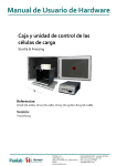
Hardware User’s Manual Behavioral box and load cell control unit Startle & Freezing References: LE116 (76-0280), LE111 (76-0281), LE115 (76-0328), LE119 (76-0286) Version: V22/10/2014 Panlab, s.l.u C/Energía, 112 08940 Cornellà de Ll.(Barcelona) Spain www.panlab.com International Calls: +34 934 750 697 Domestic Call: 934 190 709 Fax: +34 934 750 699 [email protected] Limitation of Liability PANLAB does not accept responsibility, under any circumstances, for any harm or damage caused directly or indirectly by the incorrect interpretation of what is expressed in the pages of this manual. Some symbols may have more than one interpretation by professionals unaccustomed to their usage. PANLAB reserves the right to modify, in part or in total, the contents of this document without notice. 1. SYMBOLS TABLE Recognising the symbols used in the manual will help to understand their meaning: DESCRIPTION SYMBOL Warning about operations that must not be done because they can damage the equipment Warning about operations that must be done, otherwise the user can be exposed to a hazard. Protection terminal ground connection. Warning about a hot surface which temperature may exceed 65ºC Warning about a metal surface that can supply electrical shock when it’s touched. Decontamination of equipments prior to disposal at the end of their operative life Waste Electrical and Electronic Equipment Directive (WEEE) 2. GOOD LABORATORY PRACTICE Check all units periodically and after periods of storage to ensure they are still fit for purpose. Investigate all failures which may indicate a need for service or repair. Good laboratory practice recommends that the unit be periodically serviced to ensure the unit is suitable for purpose. You must follow preventive maintenance instructions. In case equipment has to be serviced you can arrange this through your distributor. Prior to Inspection, Servicing, Repair or Return of Laboratory Equipment the unit must be cleaned and decontaminated. Decontamination prior to equipment disposal In use this product may have been in contact with bio hazardous materials and might therefore carry infectious material. Before disposal the unit and accessories should all be thoroughly decontaminated according to your local environmental safety laws. Behavioral box and load cell control unit 2 3. UNPACKING AND EQUIPMENT INSTALATION WARNING: Failure to follow the instructions in this section may cause equipment faults or injury to the user. A. No special equipment is required for lifting but you should consult your local regulations for safe handling and lifting of the equipment. B. Inspect the instrument for any signs of damage caused during transit. If any damage is discovered, do not use the instrument and report the problem to your supplier. C. Ensure all transport locks are removed before use. The original packing has been especially designed to protect the instrument during transportation. It is therefore recommended to keep the original carton with its foam parts and accessories box for re-use in case of future shipments. Warranty claims are void if improper packing results in damage during transport. D. Place the equipment on a flat surface and leave at least 10 cm of free space between the rear panel of the device and the wall. Never place the equipment in zones with vibration or direct sunlight. E. Once the equipment is installed in the final place, the main power switch must be easily accessible. F. Only use power cords that have been supplied with the equipment. In case that you have to replace them, the spare ones must have the same specs that the original ones. G. Make sure that the AC voltage in the electrical network is the same as the voltage selected in the equipment. Never connect the equipment to a power outlet with voltage outside these limits. For electrical safety reasons you only can connect equipment to WARNING power outlets provided with earth connections . This equipment can be used in installations with category II overvoltage according to the General Safety Rules. The manufacturer accepts no responsibility for improper use of the equipment or the consequences of use other than that for which it has been designed. Behavioral box and load cell control unit 3 PC Control Some of these instruments are designed to be controlled from a PC. To preserve the integrity of the equipment it is essential that the attached PC itself conforms to basic safety and EMC standards and is set up in accordance with the manufacturers’ instructions. If in doubt consult the information that came with your PC. In common with all computer operation the following safety precautions are advised. WARNING • To reduce the chance of eye strain, set up the PC display with the correct viewing position, free from glare and with appropriate brightness and contrast settings • To reduce the chance of physical strain, set up the PC display, keyboard and mouse with correct ergonomic positioning, according to your local safety guidelines. Behavioral box and load cell control unit 4 4. EQUIPMENT INSTALLATION WARNING: Failure to follow the instructions in this section may cause equipment faults or injury to the user. H. Place the equipment on a flat surface and leave at least 10 cm of free space between the rear panel of the device and the wall. Never place the equipment in zones with vibration or direct sunlight. I. Make sure that the AC voltage in the electrical network is the same as the voltage selected in the equipment. Never connect the equipment to a power outlet with voltage outside these limits. For electrical safety reasons you only can connect equipment to WARNING power outlets provided with earth connections . This equipment can be used in installations with category II overvoltage according to the General Safety Rules. The manufacturer accepts no responsibility for improper use of the equipment or the consequences of use other than that for which it has been designed. Behavioral box and load cell control unit 5 5. MAINTENANCE WARNING: Failure to follow the instructions in this section may cause equipment fault. PRESS KEYS SOFTLY – Lightly pressing the keys is sufficient to activate them. Equipments do not require being disinfected, but cleaned for removing urine, faeces and odour. To do so, we recommend using a wet cloth or paper with soap (which has no strong odour). NEVER USE ABRASIVE PRODUCTS OR DISSOLVENTS. NEVER pour water or liquids on the equipment. Once you have finished using the equipment turn it off with the main switch. Clean and check the equipment so that it is in optimal condition for its next use. The user is only authorised to replace fuses with the specified type when necessary. OPENING FLANGE SWITCH FUSE-HOLDER Figure 1. Power inlet, main switch and fuse holder. FUSE REPLACEMENT OR VOLTAGE SETTING CHANGE In case of an over-voltage or other incident in the AC net making it impossible to turn on the equipment, or if the equipment voltage setting is incorrect, check fuses according to the following procedure. 1 Remove power cord from the power inlet. Behavioral box and load cell control unit 6 2 Open fuse-holder by pulling the flange with a regular screwdriver. Figure 2. Open fuse-holder door. 3 Extract fuse holder using the screwdriver. Figure 3. Extract fuse-holder. 4 Replace fuses if necessary. Insert fuses in the fuse-holder in the correct position. CORRECT INCORRECT Figure 4. Fuses position. 5 Insert the fuse-holder again, positioning it according to the voltage in the AC net. 115V POSITON 230V POSITION Figure 5 Fuse holder position. 6 If the fuses blow again, unplug the equipment and contact technical service. WARNING For electrical safety reasons, never open the equipment. The power supply has dangerous voltage levels. Behavioral box and load cell control unit 7 6. TABLE OF CONTENTS 1. SYMBOLS TABLE 2 2. GOOD LABORATORY PRACTICE 2 3. UNPACKING AND EQUIPMENT INSTALATION 3 4. EQUIPMENT INSTALLATION 5 5. MAINTENANCE 6 6. TABLE OF CONTENTS 8 7. INTRODUCTION 10 8. EQUIPMENT DESCRIPTION 11 8.1. LE 111 FRONT PANEL 11 8.2. LE 111 REAR PANEL 13 8.3. EXPERIMENTATION CAGE 14 8.4. SOUNDPROOF CAGE 15 9. WORKING WITH THE EQUIPMENT 16 9.1. EQUIPMENT CONNECTION 16 9.2. ADJUST TRANSDUCER GAIN 18 9.3. PREPARING THE EXPERIMENT 19 9.4. GRID CLEANING 20 9.5. TRAY CLEANING 20 9.6. TRANSPARENT DOOR CLEANING 20 9.7. WALLS CLEANING 21 10. HOW TO INSTALL THE LE 115 CONTEXTUAL KIT 22 10.1. COMPONENTS: 10.1.1. WHITE UNDER-GRID BASE 10.1.2. SMOOTH FLOOR 22 22 22 Behavioral box and load cell control unit 8 10.1.3. 10.1.4. WHITE WALLS TRANSPARENT CYLINDER 23 25 11. LE119 - AIR PUFF ACCESSORY 27 11.1. CONNECTING THE ELECTROVALVE TO THE EXPERIMENTATION CAGE 27 11.2. COMPONENTS 28 11.3. AIR VALVE DISCONNECTION 28 12. TROUBLESHOOTING 29 13. PREVENTIVE MAINTENANCE 31 14. TECHNICAL SPECIFICATIONS 32 Behavioral box and load cell control unit 9 7. INTRODUCTION The LE 111 unit has 2 functions: a) Amplify and filter the signal coming from the load cell, which is placed in the experimentation cage. It displays the animal movement on an activity indicator. It also sends the data to the computer for analysis in the program. The movements that the animal makes on the grid (fear conditioning) or the forced convulsions (startle reflex) are registered by the load cell as mass displacement. b) Amplify the acoustic signal to stimulate the animal in the experimentation cage. This audio amplifier takes the output signal of the LE 118 and sends it to the speaker in the experimentation chamber. Figure 6. LE 111 Load Cell Coupler. This system features an improvement over conventional systems that use photoelectric cells, which give discrete results (steps in the movement detection). Systems based on load cells give continuous and accurate data. With the appropriate response analysis, it is even possible to identify different typologies associated with animal behaviour. WARNING: When using this equipment hearing protections should be used as to avoid taking damage due to the high acoustic levels, the sound can reach up to 120 dB. Behavioral box and load cell control unit 10 8. EQUIPMENT DESCRIPTION 8.1. LE 111 FRONT PANEL ON Use/Off AC/DC FILTER GAIN ZERO OUTPUT CELL RUNNING Figure 7. LE 111 Front Panel. ON: Green coloured led that remains on when the main switch is on. USE/OFF: This selector enables/disables the load cell signal. It facilitates quick deactivation of the cage signal and measurements. It is useful when placing/removing an animal from the cage and when a register is begun/concluded. This selector must be in the USE position when an experiment is being conducted. AC/DC: This selector acts in the coupling of the signal: - DC: The unit measures the absolute value of the transducer signal (continuous and alternate values). This mode is useful for: Adjusting and equalizing the sensibility in several control units. When equivalence between mass and the electrical signal that the equipment gives is desired. - AC: The unit only measures the alternate changes in the transducer signal (by removing the continuous part of the signal). This is the normal working mode, as only the changes of mass are needed. ZERO: This potentiometer only acts in DC. It can be used to adjust the output to 0 when there is no signal (it compensates for the offset of the transducer and the weight of the grid). Behavioral box and load cell control unit 11 AC FILTER (HZ): This control only works in AC mode. It selects the cut frequency of the low pass filter. The value displayed is the value at which the signal will have an attenuation of 3 dB. At 0.2 Hz the unit will take slower movements than at 1 Hz. GAIN: This is the factor by which the signal of the load cell is amplified to pass to the output. More gain is needed for mice than for rats. CELL RUNNING: This activity indicator shows the absolute value of the output signal. - In AC: It displays the movement. - In DC: It displays the mass. OUTPUT: The output signal is the load cell multiplied by the gain, and filtered if it is in AC mode. Behavioral box and load cell control unit 12 8.2. LE 111 REAR PANEL LOAD CELL PLATFORM CONTROL LOAD CELL AMPLITUDE AIR SHOCKER CHAMBER MAIN SWITCH Figure 8. LE 111 Rear Panel. LOAD CELL PLATFORM: This connector takes the signal coming from the load cell placed under the platform of the experimentation cage. CONTROL: This connector joins the LE 111 with the LE 118 for communication. ADJUST LOAD CELL: Fine adjustment of the GAIN. The gain can be increased/decreased. This potentiometer can be used to: - Give the total gain of the unit an intermediate value with respect to the scale in the GAIN selector values, for example 3000. - Couple several LE 111 modules with their load cells so that they give the same signal when the same weight is applied. ADJUST AMPLITUDE: Fine adjustment of the amplitude of the audio signal (it changes the volume). This potentiometer can be used to: - Adjust the volume in the cage to a desired value, for example 80dB. - Couple several LE 111 with their speakers to get the same acoustic volume. SHOCKER: Controls the LE 100-26 shocker through the External Time located on its rear panel. AIR: Opens an electro-valve to supply an air stimulus to the animal. An external source of pressured air must be used as a compressor. CHAMBER: Controls the chamber speaker and light. MAIN SWITCH: The main switch, the fuse holder and the power inlet. Behavioral box and load cell control unit 13 8.3. EXPERIMENTATION CAGE LIGHT DOOR SPEAKER BOX PLATFORM GRID Figure 9. Cage. The cage has the speaker box on its top. There are 2 connectors, one for interfacing with the LE 111 and the other for the light. There is a load cell under the platform to detect animal movement in response to the pulse. The grid has a delta 9 connector to administer shock when necessary. Behavioral box and load cell control unit 14 8.4. SOUNDPROOF CAGE The Soundproof cage is designed to contain the experimentation cages. It has additional sound insulation with an internal foam coating. Figure 10. Soundproof cage front and side view. There is a fan on the left wall to provide ventilation. There is a led lamp on the upper part of the rear inner wall with adjustable intensity. Figure 11. Fan and Lamp. There is a small box with the controls: INTENSITY C O N N E C T O R POWER POWER: main switch that turns on fan and light. POWER LED: 3mm red led that comes on when power switch is on. INTENSITY: knob used to regulate led lamp intensity. CONNECTOR: this male jack on the panel is used to connect the external power supply. The power supply output must give 12V DC 1A. Figure 12. Control box. Behavioral box and load cell control unit 15 9. WORKING WITH THE EQUIPMENT 9.1. EQUIPMENT CONNECTION The following figure features an example of control over 2 cages. The LE 118 can control up to 8 cages. Figure 13. Example of two cages connections. Behavioral box and load cell control unit 16 The necessary connections are detailed in the following table. FROM 1 PC USB port 2 PC Sound card output 3* LE 118 Stations Control n 4* LE 111 Load Cell Platform 5* LE 111 Shocker 5* LE 111 Shocker 6* LE 111 Chamber 7* Cage Light 8* LE 100-26 Shock 9* LE 111 Air 10** Pressured air system 11** Valve TO LE 118 USB LE 118 Sound LE 111 Control n Cage Load Cell LE100-26 GND LE100-26 External Time Cage Speaker Box Cage Speaker Box Cage Grid Valve Valve Cage CABLE USB cable 3.5mm stereo jack cable DELTA 9 cable DIN 5 cable Mono jack to Black Banana Mono jack to Green Banana 4 pins cable Mono Jack 6.35mm DIN6 to DELTA 9 cable 3.5mm mono jack Pipe Pipe * All of these connections are necessary for each cage. ** Pneumatic circuit connections. Behavioral box and load cell control unit 17 9.2. ADJUST TRANSDUCER GAIN To adjust transducer gain proceed as follows: 1 Take the animal and the restrainer from the cage. 2 Set the USE/OFF selector in USE position. 3 Set the AC/DC selector in DC position. 4 Adjust the GAIN to 200. 5 Adjust the activity indicator to zero with the help of ZERO knob. 6 Set GAIN to 5000 and readjust the activity indicator to zero with the help of ZERO knob. 7 Put a 20gr weight on the grid. The activity indicator will show a value. This value can be increased/decreased with the Adjust Load Cell potentiometer on the rear panel. It must be adjusted so that with the weight of 20gr it displays a value of 1.0. Behavioral box and load cell control unit 18 The value shown by the activity indicator and the voltage in the BNC connector labelled OUTPUT are respectively with 20gr the following: GAIN INDICATOR OUTPUT 5000 1 2V 2000 0.4 800mV 1000 0.2 400mV 500 0.1 200mV 200 0.04 80mV 9.3. PREPARING THE EXPERIMENT Once all the connections are completed, proceed as follows to prepare the experiment. 1 Set the USE/OFF selector in the OFF position. 2 Set the AC/DC selector in the AC position. 3 Set the FILTER selector to 0,5Hz. 4 Adjust the GAIN to 1000. 5 Place the animal on the cage. Behavioral box and load cell control unit 19 6 Set the USE/OFF selector in USE position. 7 Look the movement of the activity indicator, if the signal is low then you must increase the GAIN. 9.4. GRID CLEANING When there is dirt in the grid the electrical shock flows through it. This will produce erroneous data during the experiment because the animal behaviour to the shock negative reinforcement will not be correct (it will not receive punishment). In order to clean the grid you can use water and soap taking care to dry it afterwards. The grid set can be removed from the tray in order to clean it. Be sure to dry well the DB9 connector, otherwise contacts will rust with time. Special care must be taken in cleaning the plastic between grids, because urine is a good electrical conductor and current flows through it. 9.5. TRAY CLEANING The tray that contains the grid collects faeces and urine, it should be cleaned after each experiment. In order to clean it, the tray should be removed from the cage and washed with a soapy solution, finally it should be dried. 9.6. TRANSPARENT DOOR CLEANING WARNING: In order to clean transparent door never use neither alcohol nor alcoholic derived products, otherwise stripes will appear in the transparent plastic. To clean the door you can use a slightly wet cloth and afterwards dry it with a dry cloth. If it’s too dirty it can be cleaned with a cloth with a soapy solution, afterwards remove the foam with a wet cloth and finally dry it with a dry cloth. Behavioral box and load cell control unit 20 9.7. WALLS CLEANING To clean the walls a slightly wet cloth can be used, afterwards it should be dried with a dry cloth. If the walls are too dirty it can be cleaned with a cloth wet in a soapy solution, afterwards remove the foam with a wet cloth and finally dry it with a dry cloth. Behavioral box and load cell control unit 21 10. HOW TO INSTALL THE LE 115 CONTEXTUAL KIT The contextual kit is an accessory provided with the Panlab combined Startle & Freezing system (STARTFEAR), for changing the context of the box when running Cue-dependent Fear Conditioning experiments. 10.1. COMPONENTS: White under-grid base. Smooth floor. White walls. Transparent cylinder. 10.1.1. WHITE UNDER-GRID BASE The white under-grid base is used to change the colour of the floor base when the user wishes to keep the grid during the test phase of the Cue-dependent Fear Conditioning experiment. Figure 14. White under-grid base. 1) Remove the grid from the tray. 2) Place the white flexible floor on the floor of the tray. 3) Place the grid on the tray again. 4) Place the tray-grid set in the box. 10.1.2. SMOOTH FLOOR The smooth floor is used to change the texture of the floor during the Test so that the box can provide a different tactile cue to the subject. As no shocks are delivered Behavioral box and load cell control unit 22 during this phase of the experiment, grid-animal contact is not necessary. The smooth floor does not impair the sensitivity of the system in detecting animal movements. 1) Cover the grid with the aluminium floor. 2) Place the set back into the cage. Figure 15. Smooth floor. 10.1.3. WHITE WALLS The white walls change the visual perception of the subject with respect to the colour of the box. Three walls are provided, including one for the left side (featuring the light). Figure 16. White walls. 1) Open the door of the box and partially unscrew the 4 white screws of the top cover of the box. Figure 17. White screws. Behavioral box and load cell control unit 23 2) Maintain the cover slightly raised and insert the bent part of the white wall in the gap between the cover and the top part of the original black wall. Figure 18. White wall placement. 3) Repeat the same process for all 3 walls (left, right and back walls). Figure 19. White walls placement. 4) Screw the 4 white screws of the top cover back down to keep the walls firmly fixed in place. 5) Once fixed, it is important to ensure that the bottom parts of the 3 walls are NOT touching the top part of the floor/grid tray, as this may affect system sensitivity. Behavioral box and load cell control unit 24 10.1.4. TRANSPARENT CYLINDER The transparent cylinder is used to change the spatial perception of the internal space inside the box. The cylinder is provided with an open top for the light stimulus placed on the left wall and 3 small holes on its bottom to ensure fixation of the whole cylinder in the box without any contact with the floor. The cylinder can be fixed in the box with the original black walls or in the box in which the contextual white walls have been placed (this is why the cylinder is transparent; so that the subject can perceive the new colour of the box when visual and spatial contexts are both changed). Figure 20. Transparent cylinder. 1) The cylinder is provided with 3 small screws. 2) Screw the screws into the 3 small holes found on the bottom part of the 3 original black walls of the box. Figure 21. Screws. Behavioral box and load cell control unit 25 3) Insert the cylinder by the front door pushing it laterally, and matching its 3 holes with the 3 screws standing out from the walls. Figure 22. Placement of the transparent cylinder. 4) Once fixed, it is important to ensure that the bottom part of the cylinder is NOT touching the top floor/grid tray, as this may affect system sensitivity. NOTE: in standard boxes, the back wall is black, and not transparent, as shown in some of the photographs. Behavioral box and load cell control unit 26 11. LE119 - AIR PUFF ACCESSORY 11.1. CONNECTING THE ELECTROVALVE TO THE EXPERIMENTATION CAGE In the left side wall of the experimentation cage there is a headless screw, it must be unscrewed and replaced by record (2). Afterwards the stainless steel tube (1) must be introduced (in mouse model the bended part is longer than in rat model). Then insert the plastic cone (3) in the tube and once the tube (1) is correctly positioned with respect to the restrainer, screw the nut (4). The stainless steel tube (1) must be at least 1.5cm out of nut (4) so that it can be connected to the electrovalve (5). When connecting the cage to the electrovalve there are two options. One is to connect the nut (4) directly to the electrovalve (Option A). The other one would be to place the electrovalve far from the experimentation cage, in this case and additional connection should be made between the electrovalve (5) and the nut (4) (Option B). Option A Connect the electrovalve (5) directly to tube (1). OPTION A Behavioral box and load cell control unit 27 Option B Place the electrovalve far from the experimentation cage OPTION B 11.2. COMPONENTS When the LE119 module is sold it comes with the following components: 1 Electrovalve with its connection cable. 2 Stainless steel tubes, 1 for each animal. 1 Racord to pass the wall. 1 Racord to extend the connection (Option B). 2 plastic tubes 1m long. 1 Allen key number 4. 11.3. AIR VALVE DISCONNECTION To disconnect the air valve from the stainless steel tube (Option A) or from the plastic pipe (Option B) proceed as follows. Press the black plastic ring inside (1) , while it is pressed remove the valve from the tube/pipe. 1 Flow sense Behavioral box and load cell control unit 28 12. TROUBLESHOOTING This table features instructions to solve the most frequent problems. PROBLEM The equipment does not start up. Air stimulus does not work. The animal does not receive electrical shock. Light stimulus does not turn on. White noise does not sound. Behavioral box and load cell control unit SOLUTION Ensure that the voltage of mains is the same as that selected in the fuse holder. Check the condition of the fuses. Check connections (see Figure 13). Check that AIR led lights on the front panel of LE118, if not can be a problem in the drivers or the USB cable connection. Check that the source of compressed air supplies air to the electro valve. Check connections (see Figure 13). Check that SHOCK led lights on the front panel of LE118, if not can be a problem in the drivers or the USB cable connection. Check that SHOCK/ CALIBRATION switch in the Shocker is in the SHOCK position. Check that the INTENSITY knob in the Shocker is set to a value higher than 0mA. Check that the grid is clean (urine and excrements can conduct current). Check connections (see Figure 13). Check that LIGHT led lights on the front panel of LE118, if not can be a problem in the drivers or the USB cable connection. Check that the bulb is not burned out. Check connections (see Figure 13). 29 The tone does not sound. The VU meter needle does not move. The computer does not detect the animal's movements. Behavioral box and load cell control unit Check that NOISE led lights on the front panel of LE118, if not can be a problem in the drivers or the USB cable connection. Check in the program that the duration and selected Sound level are enough so that the white noise is audible. Check connections (see Figure 13). Check that SOUND led lights on the front panel of LE118, if not can be a problem in the drivers or the USB cable connection. Check in the program that the duration and selected Sound level are enough so that the tone is audible. Below 100dB the needle will not move being the minimum. Check connections (see Figure 13). Check with the help of PC speakers that the sound card of the PC runs. Ensure that the grid and tray are correctly positioned. Remove the tray and check in the four tray supports of the platform, when pressing on them, they are not blocked and move. Increase the gain with the GAIN knob on the front panel of the LE111. 30 13. PREVENTIVE MAINTENANCE EXPERIMENT MONTHLY GRID CLEANING TRAY CLEANING RESTRAINER CLEANING1 TRANSPARENT DOOR CLEANING WALLS CLEANING CHECK GRID AND TRAY PLACING 1 Only when you work with Startle experiment. Behavioral box and load cell control unit 31 14. TECHNICAL SPECIFICATIONS POWER SUPPLY Input voltage: Frequency: Fuse: Maximum power: Conducted noise: 115 /230 VAC 50 /60 Hz 2 fuses 5x20mm 1A 250V Fast 60 W EN55022 /CISPR22/CISPR16 class B ENVIRONMENTAL CONDITIONS Operating temperature: Operating relative humidity: Storage temperature: 10°C to +40°C 0% to 85% RH, non-condensing 0°C to +50°C, non-condensing SOUND AMPLIFIER Power supply: Max current: Input sensibility: Input impedance: Output impedance: Frequency range: Distortion (@1W): Distortion max power: Power R.M.S: Power musical: Slew rate: Linearity error: Output ranges: Range adjust amplitude: BRIDGE AMPLIFIER Power supply: Max current: Distortion max: Slew rate: Linearity error: Gain ranges: Low pass filter: High pass filter: Balance Zero: Output full-scale: Range adjust load cell: LOAD CELL Excitation voltage: Input impedance: Output impedance: Sensibility: Total error: Thermal zero shift: Behavioral box and load cell control unit +/-32V 1.5A +/- 10V (20Vpp) 820k – 1320K 8 20 -20000Hz 0.01% 1% 60 W 85.5 W 15V/us <1% in 10 steps +- 25% respect central point 100% to 63% respect max +12V 0.1 A 0.001% 5V/us < 0.1% 200, 500, 1000, 2000, 5000 0.2 Hz, 0.5 Hz, 1 Hz 22 Hz 500 gr -2V a +2V +/- 50% respect central point 100% to 33% respect max 12V 409 ohm 350.9 ohm 1.95 mV/V 47uV/V 0.050 %C.N./10ºC 32 Thermal sens. Shift: < 0.120 %C.N./10ºC SHOCKER OUTPUT TTL output level low: 0.5Vmax high 2.4Vmin LIGHT OUTPUT TTL output level low: 0.5Vmax high 2.4Vmin CONNECTOR CONTROL (9 pins) Pin 5 9 2 3 7.8 1 6 Function output signal analogic gnd TTL input light TTL input shock gnd digital load cell input + load cell input - CONNECTOR CHAMBER (4 pins) Pin B D A C Function loudspeaker loudspeaker TTL output light GND digital SPEAKER Diameter: Magnet: Impedance: Music maximum power: Nominal power: Frequency range: 165mm 170g 4 170 W 35 W 200Hz – 10kHz DIMENSIONS Width x Height x Depth: Weight: 232 mm x 124 mm x 297 mm 5.31 kg Behavioral box and load cell control unit 33 DECLARACIÓN DE CONFORMIDAD DECLARATION OF CONFORMITY DECLARATION DE CONFORMITÉ Nombre del fabricante: Manufacturer’s name: Nom du fabricant: Panlab s.l.u. www.panlab.com [email protected] Dirección del fabricante: Manufacturer’s address: Adresse du fabricant: Energía, 112 08940 Cornellà de Llobregat Barcelona SPAIN Declara bajo su responsabilidad que el producto: Declares under his responsibility that the product: Déclare sous sa responsabilité que le produit: Load Cell Coupler Marca / Brand / Marque: PANLAB Modelo / Model / Modèle: LE 111 – LE 116 Cumple los requisitos esenciales establecidos por la Unión Europea en las directivas siguientes: Fulfils the essential requirements established by The European Union in the following directives: Remplit les exigences essentielles établies pour l’Union Européenne selon les directives suivantes: 2006/95/EC 2004/108/EC 2012/19/EU 2011/65/EU 2006/42/EC Directiva de baja tensión / Low Voltage / Basse tensión Directiva EMC / EMC Directive / Directive CEM La Directiva de Residuos de Aparatos Eléctricos y Electrónicos (WEEE) / The Waste Electrical and Electronic Equipment Directive (WEEE) / Les déchets d'équipements électriques et électroniques (WEEE) Restricción de ciertas Sustancias Peligrosas en aparatos eléctricos y electrónicos (ROHS) / Restriction of the use of certain Hazardous Substances in electrical and electronic equipment (ROHS) / Restriction de l'utilisation de certaines substances dangereuses dans les équipements électriques et électroniques (ROHS) Directiva mecánica / Machinery directive / Directive mécanique Para su evaluación se han aplicado las normas armonizadas siguientes: For its evaluation, the following harmonized standards were applied: Pour son évaluation, nous avons appliqué les normes harmonisées suivantes: Seguridad / Safety / Sécurité: EMC: FCC: Safety of machinery: EN61010-1:2011 EN61326-1:2012 Class B FCC47CFR 15B Class B EN ISO 12100:2010 En consecuencia, este producto puede incorporar el marcado CE y FCC: Consequently, this product can incorporate the CE marking and FCC: En conséquence, ce produit peut incorporer le marquage CE et FCC: En representación del fabricante: Manufacturer’s representative: En représentation du fabricant: Carme Canalís General Manager Panlab s.l.u., a division of Harvard BioScience Cornellà de Llobregat, Spain 25/06/2014 Behavioral box and load cell control unit 34 Behavioral box and load cell control unit 35