1
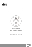
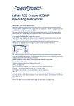
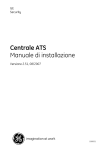
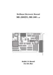
Conventional
microprocessor
controlled fire panels
FP400
Instruction manual for
installation, use and
maintenance
Version 2.1 / August 2003
55370014
Aritech is a GE Interlogix brand.
www.aritech.com
© 2003 GE Interlogix B.V.. All rights reserved. GE Interlogix B.V. grants the right to reprint this manual for internal use only. GE
Interlogix B.V. reserves the right to change information without notice.
Installation, Configuration and User Manual for Conventional Fire Panels FP400 series v2.1
2
TABLE OF CONTENTS
1
Introduction............................................................................................................................................ 5
1.1 Glossary of symbols...................................................................................................................... 5
1.2 Glossary of terms .......................................................................................................................... 5
1.3 Content of package ....................................................................................................................... 7
1.4 Overview of the FP400 series ....................................................................................................... 8
1.5 Regulations ................................................................................................................................... 9
1.6 Safety warnings and precautions................................................................................................ 10
1.7 Compatibility with other equipment ............................................................................................. 10
2
Installation guide ................................................................................................................................. 11
2.1 Installation ................................................................................................................................... 11
2.1.1
Tools required.............................................................................................................. 11
2.1.2
Removal of the fire panel cover................................................................................... 11
2.1.3
Fire panel location ....................................................................................................... 11
2.1.4
Fixing the fire panel to the wall .................................................................................... 12
2.1.5
Selecting a language ................................................................................................... 12
2.2 Electrical connections ................................................................................................................. 13
2.2.1
Main power connection................................................................................................ 14
2.2.2
Connection of a zone................................................................................................... 16
2.2.2.1 Connection of detectors ............................................................................... 16
2.2.2.2 Connection of remote LED indicators .......................................................... 17
2.2.2.3 Connection of manual call points ................................................................. 18
2.2.3
Class change input connection.................................................................................... 19
2.2.4
Auxiliary 24 VDC output connection ............................................................................ 19
2.2.5
Potential free relay output connection ......................................................................... 20
2.2.6
Resetable 24 VDC output ............................................................................................ 20
2.2.7
Connecting sounders and bells ................................................................................... 21
2.3 Configuration options .................................................................................................................. 22
2.3.1
Configuration of sounder delays.................................................................................. 22
2.3.2
Configuration for remote reseting ................................................................................ 23
2.3.3
Configuration for active end-of-line resistors ............................................................... 23
2.4 Master module options................................................................................................................ 24
2.4.1
Potential free relay master modules ............................................................................ 25
2.4.2
Master module with 24 VDC outputs (for sounders or other supervised outputs)....... 25
2.4.3
Configuration of the master module microswitch ........................................................ 26
3
System start-up ................................................................................................................................... 29
3.1 System check.............................................................................................................................. 29
3.2 System power-up ........................................................................................................................ 29
3.3 Functional test............................................................................................................................. 29
4
User Guide ........................................................................................................................................... 31
4.1 Description of control panel......................................................................................................... 31
4.1.1
LED indicators ............................................................................................................. 31
4.1.2
Accoustic indicators ..................................................................................................... 32
4.1.3
Control panel buttons................................................................................................... 32
4.1.4
Operating modes ......................................................................................................... 33
4.2 What to do in case of a fire or fault ............................................................................................. 35
5
Maintenance......................................................................................................................................... 37
6
Troubleshooting guide ....................................................................................................................... 38
7
Technical specifications..................................................................................................................... 39
Installation, Configuration and User Manual for Conventional Fire Panels FP400 series v2.1
3
8
Appendix: Configuration of addresses for master modules .......................................................... 41
Installation, Configuration and User Manual for Conventional Fire Panels FP400 series v2.1
4
1 INTRODUCTION
This manual contains all the technical information required for the correct installation of the system, together
with user information for operating the panel. It also includes information for maintenance and a
troubleshooting guide for the most common problems.
The range of FP400 fire alarm and detection panels has five models: FP402 of two zones, FP404 of four
zones, FP408 of eight zones, FP412 of twelve zones and FP416 of sixteen zones. The series has been
designed to cover the needs of small to mid-sized installations such as schools, homes, shops, small and
medium-size businesses, etc.
It indicates the fire warnings to security personnel, together with any functioning error. For this purpose, it
uses conventional fire detectors.
1.1 Glossary of symbols
The following is the list of the symbols used in this manual to make it more easily
understood.
PRECAUTIONS
Earth connection: This connection is essential. Always verify that this is
correct.
Electronic equipment sensitive to electrostatic discharge: When working
with the electronic circuitry, use anti-static bracelet to avoid damage to these.
Possibility of «HIGH VOLTAGE» electrical discharge: Please take
precautions to avoid personal injury.
Lead batteries: Risk of explosion in case of short-circuit and corrosion in case
of spillage.
Source of external radiation: Motors, radio antennas, etc.
Warning/Attention: Follow these indications carefully to avoid personal injury
and/or damage of the equipment.
1.2 Glossary of terms
Fire alarm:
Acoustic and visual signal to warn of a possible fire.
False alarm:
Fire alarm due to causes other than fire.
Fault:
Breakdown of the system or electrical power that endangers the
correct functioning of the system.
Fault warning:
Acoustic and visual signal to warn of a possible system fault.
Alarm bell:
Acoustic element for fire warning.
Front panel:
Front panel of the unit containing the indicators and control
buttons.
Installation, Configuration and User Manual for Conventional Fire Panels FP400 series v2.1
5
Casing:
Front protective cover of the unit fastened to the metal frame with
two screws.
Frame:
Metal box that holds all the electronic elements and that enables it
to be fastened to the wall.
EMC:
ElectroMagnetic Compatibility. The capability of the fire panel to
withstand external electromagnetic interference without its
operation being affected, as well as the limiting of the generation of
electronic signals that may alter the functioning of other equipment.
Silence Buzzer:
Button that allows the muting of the internal buzzer of the fire
panel.
System fault:
A fault in the fire system.
Fire:
Combustion that requires investigation and corrective action in
order to prevent threats to life or damage of assets.
Maintenance:
Routine check of the system (includes cleaning, alignment,
adjustment and parts replacement). This is normally done on predetermined dates.
Zone map:
Diagram representing the physical limits of the zones and their
access routes.
Assembly:
Process of installing and interconnecting system elements and
components.
Norms:
Regulations concerning fire detection equipment.
Remote LED indicator: External light indicator that constitutes part of a fire detection and
alarm system.
Manual Call Point:
Equipment that enables direct operation of the sounders in a
system by human intervention.
Emergency plan:
Pre-established procedure that is carried out when a fire alarm is
raised.
Start-up:
Process via which the installer checks that the system fulfils the
established requirements.
Commissioning:
Decision that determines that the installed system meets the
requirements of a previously agreed specification. Commissioning
may be carried out by the buyer or by third parties.
Repair:
Non-routine work required to re-establish efficient functioning of an
installed system.
Reset:
Button on the front panel that allows the restarting of the system.
End-of-line resistor:
A 4k7 Ohm resistor that is placed at the end of each detector zone
and allows the detection of line faults in the installation.
Fire signal:
Signal to indicate the presence of a fire.
Fault signal:
Signal to indicate the presence of a fault.
Alarm sounder:
Acoustic device to warn people about a fire.
Verification:
Process via which the installer or another contracted party may
satisfactorily demonstrate to the user that the installed system
meets the established requirements.
Zone:
Physical subdivision of the protected premises in which a function
can be carried out independently from any other subdivision.
Installation, Configuration and User Manual for Conventional Fire Panels FP400 series v2.1
6
Buzzer:
Internal acoustic element of the panel to warn of an alarm or fault.
1.3 Content of package
Once the panel has been removed from its original packaging, check the following material is
included:
•
1 fire panel
•
4k7 Ohm end-of-line resistors (one per zone plus 2, one for each sounder output).
•
1 off 5x20 mm 2 A fuse
•
1 off 5x20 mm 1 A fuse
•
2 keys
•
1 instructions manual for installation, use and maintenance
•
1 sheet with multiple language inserts for selecting the language.
•
1 bridge to connect the batteries.
Figure 1: Package contents
FP400
Before starting the installation, check that the contents of the package are correct and that it
is in good condition. If any defects exist, repackage the panel and contact your distributor.
Installation, Configuration and User Manual for Conventional Fire Panels FP400 series v2.1
7
1.4 Overview of the FP400 series
The FP400 series conventional fire panel series has two different box sizes:
•
Small size: for 2 or 4 zones (FP402 or FP404)
•
Large size: of 8, 12 or 16 zones (FP408, FP412 and FP416)
Figure 2: FP416 layout
2
3
1
12
4
6
5
7
11
10
8
13
9
14
Figure 3: FP404 layout
2
1
9
4
3
12
8
7 5
13
6
11
10
14
1. Mains connector (110 VAC / 230 VAC)
2. Zones connectors (from 2 to 4, or 8, 12 or 16,
depending on fire panel model)
3. Output connectors: Auxiliary 24 VDC, Fire and Fault
Relays and Sounders
4. 24V Resetable Output - 0.1 A fuse
5. Sounder output #1 - 0.3 A fuse
6. Auxiliary 24 VDC Output - 0.3 A fuse
7. Sounder output #2 - 0.3 A fuse
8.
9.
Configuration micro switch
Sounder delay programming trim pot
10. 5 A battery fuse
11.
12.
13.
14.
Transformer connector
Front panel connector
Master module output connector
24 V battery connector
Installation, Configuration and User Manual for Conventional Fire Panels FP400 series v2.1
8
Independent of the number of zones, all FP400 panels have the following common
functionality:
•
Enable / Disable per zone.
•
Test per zone.
•
Activation / Silencing of sounders.
•
Programming of sounder delays.
•
Supervision of main power, batteries and outputs.
•
Differentiation of manual call point and/or detector alarm signal within the same
zone.
•
Remote reset optional operating mode.
•
Active end-of-line optional operating mode.
•
Programming of delays for sounders depending on the source of the alarm i.e.
detectors or manual call point.
•
Relay master modules (optional)
•
Sounder master modules (optional)
Inputs/Outputs:
Figure 4: Inputs/outputs of FP400 fire panels
RFL 4k7
3
2
5
RFL 4k7
6
4
+
+
+
+
Z1 Z2 Z3
+
+
C NO NC C NO NC
RFL 4k7
+
+
+
Z16
1
1.
2.
3.
4.
5.
6.
Zones input
Class change input.
Auxiliary 24 VDC output.
General alarm and fault relay (potential free)
24 VDC resetable output.
Two supervised 24 VDC sounder outputs, with programmable delay.
1.5 Regulations
The FP400 conventional fire panel series has been designed according to EN54-2 and
EN54-4 standards of 1997.
The EN54-2 standard includes some basic requirements and some optional ones. The
optional requirements that the FP400 series meet are:
SUBJECT
CHAPTER
DESCRIPTION
Indications
8.3
Fault signals
Installation, Configuration and User Manual for Conventional Fire Panels FP400 series v2.1
9
SUBJECT
Controls
Outputs
CHAPTER
8.4
7.12
7.11
10
7.8
DESCRIPTION
Notification of loss of all external power
Coincidence detection
Output delays
Test status indication
Output for Fire alarm devices
1.6 Safety warnings and precautions
These precautions explain how to use the equipment correctly and safely, preventing any
injury to oneself an others. This section has been subdivided into a WARNING section and a
PRECAUTION section according to the nature of potential injury and damage to equipment.
Read all the sections carefully before continuing.
WARNING: Always follow the basic precautions listed in order to avoid the possibility of
serious injury and even death due to electrical shock, short-circuits, equipment damage, fire
and other hazards. These precautions include but are not limited to the following:
•
Do not touch the inside of the panel when the equipment is connected at 230 VAC. It
may be handled by specialized personnel only.
•
Do not try to repair the electronic circuit on site.
•
If the panel has to be returned to the factory for repair, use the original packaging
and do not include the batteries.
PRECAUTION: Always follow the basic precautions set forth below to avoid possible injury
to yourself and other persons, damage to the equipment or other property. These
precautions include but are not limited to the following:
•
Do not install the panel near sources of extreme heat or excessive vibration.
•
Do not install the panel near other electrical devices such as television sets, radios,
speakers, radio frequency transmitters, etc. These devices may produce high-level
interference that prevents the panel from functioning correctly.
•
Place the panel in a horizontally level position at eye level.
•
Do not open cable entrance holes in any place other than those provided.
•
Check the characteristics of the mains supply and ensure that it coincides with those
of the panel.
•
Connect to earth. This is essential.
•
Disconnect the power supply and batteries in case of fault and request the
assistance of qualified personnel.
1.7 Compatibility with other equipment
The family of FP400 panels is compatible with all ranges of Aritech conventional fire
detectors and manual call points. Although other manufacturers detectors may be used,
proper functioning cannot be guaranteed.
Installation, Configuration and User Manual for Conventional Fire Panels FP400 series v2.1
10
2 INSTALLATION GUIDE
2.1 Installation
This section gives the exact definition of the steps to be taken for the correct installation of
the FP400 series fire panels. Read the entire content of this manual carefully before
beginning the installation of the system. Not following the instructions correctly may cause
damage to the equipment.
The FP400 series has been developed in compliance with the EN54-2 and UN54-4 (UNE
23007) standard and have approvals pending. It must be installed by qualified personnel,
taking into account the EN54-14 (UNE 23007-14) standard as well as the corresponding
local authority’s laws.
2.1.1
2.1.2
Tools required
•
A flat screwdriver for the connection plates and a Philips screwdriver for the screws
of the front cover.
•
Wire strippers.
•
Tester.
•
Drill, bits, plugs and screws in accordance with the type and thickness of the wall on
which the fire panel is to be fitted.
•
Level meter.
Removal of the fire panel cover
First of all, remove the front cover from the fire panel after removing the two fastening
screws.
Figure 5: To open the panel, remove the screws and the cover.
2.1.3
Fire panel location
The fire panel must be installed in a clean and dry place that is free from vibrations and
has a temperature between 5º and 40ºC. The relative humidity, in the worst-case, may not
exceed 95% without condensation. The risk of fire should be minimal and the location
must be protected by the fire detection system. Any risk of mechanical damage must be
avoided.
Installation, Configuration and User Manual for Conventional Fire Panels FP400 series v2.1
11
2.1.4
Fixing the fire panel to the wall
General recommendations
Place the fire panel at an approximate height of 1.5 m in a place with easy access and
where the light indicators are easily distinguishable. Ensure that, once the fire panel is
attached to the wall, the front casing can be removed without any obstacle. Bear in mind
that the weight of the fire panel together with the batteries may be quite high, so select the
correct size of plugs and screws to hold it.
Installation steps
1. Place the metal box on the wall, orientate it correctly with the help of the level and
mark with a pencil the position of the 3 or 4 screws (depending on the box size).
2. Remove the box from the wall and drill the holes and place the plugs.
3. Place the fire panel on the wall and attach it with the right screws.
Do not use the fire panel metal box as a guide for the drill.
Before fixing the frame to the wall, make the cables holes as required. Do not make holes in
the fire panel box in places other than those indicated, and avoid shavings or pieces of
removed casing dropping inside the panel. This could damage the electronic circuits. If
required, PG11-type cable adapters may be used.
2.1.5
Selecting a language
The FP400 panels allow easy changing of the desired language. Sheets of cut-out
language inserts are supplied with the panel. Select the desired language and cut the
corresponding inserts with a pair of scissors. Insert each insert in the corresponding
position on the front panel according to its number.
The sheets also contain blank inserts for configuring languages that have not been
included. These inserts may be customised with any required language.
Figure 6: Insertion of language inserts
Installation, Configuration and User Manual for Conventional Fire Panels FP400 series v2.1
12
2.2 Electrical connections
WARNING:
•
The 110 VAC or 230 VAC power must be connected to the power supply through an
external magneto-thermal switch.
•
The mains cable should have a minimum section of 1.5 mm².
•
To avoid possible short circuits and interference, the mains cable must be kept away
from the zone connection cables and from the communication ports.
Figure 7: Mains connection
In/out hole for
mains power
To ensure ‘clean’ connections, the use of PG11-type cable adapters or seals is
recommended. In this way the cable is firmly fixed to the panel. The use of pressuresensitive flanges to fix the cables to the housing of the exchange is also recommended.
If the system is exposed to a lot of electrical interference, the use of ferrite as close as
possible to the connection is recommended (see figure 7).
Once the fire panel is mounted on the wall, the connecting of equipment may start. The
loops, the mains and the additional elements are connected to the base plate through the
holes on the top. The hole located away from the rest is for the mains.
Figure 8: Example of a connection with cable seal and ferrite
CABLE ADAPTER OR
SEAL
INPUT CABLE
SLEEVE
FIRE PANEL
METAL FRAME
NUT
CONNECTION OF SCREEN TO
GROUND
CABLES
FERRITE
TERMINALS
Installation, Configuration and User Manual for Conventional Fire Panels FP400 series v2.1
CONNECTOR
SOCKET
13
In installations with potential radio frequency interference, the use of a twisted, screened
cable is recommended. Connect the cable screen to the cable adapter and ensure that the
installation is properly connected to earth.
Figure 9: Cable types
2.2.1
Main power connection
Figure 10: Location of bipolar magneto-thermal switch
Bipolar magnetothermal switch
Do not make any connections with the power supply on. Disconnect the external magnetothermal switch.
For safety, the sequence in which the connections are made must be: Mains first, then
batteries.
Do not connect the fire panel to the mains until you have completed the start-up. (See
chapter 5)
The fire panel has two power supply systems: the main supply and the batteries.
Connecting to the main supply
The fire panel must be connected to the main supply through a bipolar magneto-thermal
switch. An adequate ground connection is required. It is recommended that the ground cable
is longer than the rest so that, in case of sudden pulling, it is the last cable to be
disconnected.
Installation, Configuration and User Manual for Conventional Fire Panels FP400 series v2.1
14
For optimum fixation of the mains cable, use pressure-sensitive clamps on the housing.
Mains fuse
The FP400 series may be powered from either 230 VAC or 110 VAC. Place the mains
fuse in its proper position as indicated in
Figure 11
•
To power from 110 VAC, place the fuse in the left fuse holder.
•
To power from 230 VAC, place the fuse in the right fuse holder.
Do not use the mains fuse for connecting and disconnecting the fire panel from the mains;
use the magneto-thermal switch.
Figure 11: Mains power connection
110 VAC
230 VAC
Clamp
N
N
Mains
fuse
Mains
fuse
Connecting the batteries
The FP400 panels require 2 x12 V batteries of 2.3 Ah for the FP402 and FP404, and 2 x
12 V 7 Ah for FP408, FP412 and FP416 respectively. These are connected in series in
order to obtain 24 VDC. A bridge connector for batteries is supplied in the box together
with the fire panel. Connect the positive contact (+) of one of the batteries to the negative
contact (-) of the other.
1. Place the batteries in the space reserved for them at the bottom of the fire panel box.
2. Connect the cables taking into account the colour correspondence (red positive, black
negative). Connect the battery bridge cable between the two batteries and the two
cables that come out of the fire panel to each of the batteries.
Installation, Configuration and User Manual for Conventional Fire Panels FP400 series v2.1
15
Figure 12: Battery connection
2.2.2
Connection of a zone
A zone output can only monitor a maximum of 20 detectors or 32 manual call points. Every f
zone has only one origin and one end. The last detector or call point must therefore include
a 4k7 Ohm end-of-line resistor. It is not allowed to do T-offs of the line or place the end-ofline resistor in the zone output on the main circuit board. Only if the zone is not going to be
used it is necessary to install an end-of-line resistor in the zone output.
Figure 13: Connection of a zone
PK 20
Z1
+
Z2
+
Z 700
4K7
End of line
resistor
+
sirena
2.2.2.1 Connection of detectors
The available range of conventional detectors is as follows:
•
DI322I Ionisation smoke detector
•
DT313I Rate-of-rise detector
•
DP321I Photoelectric smoke detector
Installation, Configuration and User Manual for Conventional Fire Panels FP400 series v2.1
16
•
FD2000 Infra-red beam detector up to 100 meters (transmitter and receiver)
Figure 14: Connection of detectors
Correct
Incorrect
Smoke detector
End-of-line resistor
Incorrect
2.2.2.2 Connection of remote LED indicators
When detectors are installed in closed rooms it is advised to use remote LED indicators
to be able to know from the outside if the detector is in alarm state. The AI300 is usually
used for this purpose. It shall be connected between the RL output and the detection line
(+). See Figure 15.
24V
ARITECH 300 series
detectors
Fire panel
Figure 15: Connection of remote indicators
+
-0
End-of-line
resistor
RL
+
Remote LED
AI300
24V
Fire panel
+0
+1
-1
-0
RL
Remote LED
AI300
ARITECH 700 series
detectors
+0
+1
-1
End-of-line
resistor
Remote LED
AI672/673
Installation, Configuration and User Manual for Conventional Fire Panels FP400 series v2.1
17
2.2.2.3 Connection of manual call points
In general, all manual call point alarms must be mounted on the wall on emergency exit
routes so a distance of less than 30 meters must be covered to reach one of them. It is
recommended to place them at a height of between 1,2 and 1.5 meters from the ground.
They must be clearly visible, identifiable and accessible.
The available versions are:
•
DM700 Manual call point, flush mount without glass.
•
DM782 Hinged cover.
•
DM800 Resetable element
Manual call points such as the DM700 need a 100 Ohm 2W resistor in serial with the
normally open (NO) contact. The model DM700R already includes it. This resistor avoids
that a short-circuit is created when the call point is activated, and allows the fire panel to
identify the origin of the alarm, differentiating it from the signal given by the detector.
In general if a dry contact is connected to a zone, it shall be normally open (NO) and a
100 Ohm 2 W will be connected in serial. In this way, the fire panel is able to distinguish a
detector alarm from a call point alarm.
Installation, Configuration and User Manual for Conventional Fire Panels FP400 series v2.1
18
Figure 16: Connection of different manual call points
Detection
line
Detection
line
Detection
line
R
R= Alarm
resistance
100Ohm 2W
Manual call point
DM700 in stand-bye
DM700.
Resistor R is used to avoid a shortcircuit and differentiate the alarm
from the detector
2.2.3
R= Alarm
resistance
100Ohm 2W
DM700R.
Already includes the 100 Ohm 2 W
resistor
Class change input connection
This input allows the activation of the sounders from an external push-button. When a short-circuit
is created between these contacts, the sounders and/or bells will activate until the short-circuit is
removed. The push-button must be connected as normally open (NO).
Figure 17: Class Change
+
Class change input
2.2.4
Auxiliary 24 VDC output connection
This output allows to power auxiliary devices not included in a zone. It is protected with a fuse and
the maximum current allowed is 250 mA. It is not recommended to use this output to power
elements that have a certain current consumption in their stand-bye mode.
Installation, Configuration and User Manual for Conventional Fire Panels FP400 series v2.1
19
Figure 18: Auxiliary supply Output
+
Auxiliary 24 V output
2.2.5
Potential free relay output connection
These are outputs of potential free relays that can be activated in an alarm or fault situation.
The fault output is generally energized.
Figure 19: Potential free relay output
C NO NC C NO NC
Voltage free relay output
2.2.6
Resetable 24 VDC output
This output allows the connection of devices that require to be reset from their power connection
(this is the case with the infra-red beams). This output has 24 VDC in stand-by and when a reset is
performed from the panel, the 24 VDC is disconnected for 3 seconds.
Figure 20: Resetable 24 VDC output
+
24 VDC Resetable
output
Installation, Configuration and User Manual for Conventional Fire Panels FP400 series v2.1
20
2.2.7
Connecting sounders and bells
The FP400 series panels has 2 sounder outputs on the main board identified as SND1
and SND2. Each of these outputs allows for a supervised sounder circuit with a maximum
consumption of 250 mA per circuit.
It is required to use polarity sensitive sounders or to install a diode to prevent sounders from
being activated in stand-bye condition.
Figure 21: Sounder outputs
+
+
SND1 SND2
Sounder outputs
Use sounders or bells which consumption is lower than 250 mA.
The sounder output is activated and supplies 24 VDC when a zone alarm is activated due
to a detector or a manual call point. If a motorized alarm bell is used it is required to install
a diode in parallel in order to avoid the effect of the inverted current.
Aritech AS260 sounders do not required diode as they are polarity sensitive.
Figure 22: Sounder connections
DIODE
END OF LINE RESISTOR
Connection of polarity insensitive sounders
END OF LINE RESISTOR
Polarity sensitive sounder connection
Installation, Configuration and User Manual for Conventional Fire Panels FP400 series v2.1
21
2.3 Configuration options
2.3.1
Configuration of sounder delays
The fire panel has a trim pot on its main board for setting a delay for the sounders (from 0
to 9 minutes). This allows a delay in the activation of the sounders for a certain amount of
time after an alarm has been activated.
When this option is used, sounders are not activated immediately when a detector or
manual call point detects an alarm situation. With this operating mode active, a specific
LED on the control panel is lit.
Figure 23: Location of trim pot and micro switch required to configure the delayed mode
Trim pot for delay
programming
Micro switch
The delay can affect the alarm caused by detectors and/or manual call points depending
on the position of the different bits of a micro switch:
•
Bit 6 ON
The delay does not affect to manual call points
•
Bit 7 ON
The delay does not affect to detectors
Figure 24: Delay configuration
Configuration of the delay of
manual call points through bit 6.
Configuration of the delay of
detectors through bit 7.
If bits 6 and 7 are both in ON position, then the delay is inactive. That is, the same effect as
of positioning the trim pot to zero (0).
Installation, Configuration and User Manual for Conventional Fire Panels FP400 series v2.1
22
2.3.2
Configuration for remote reseting
Remote Reset mode changes the normal function of the class change input. If the class
change input is activated, then the reset will be activated. If the class change input
remains activated, a fault is shown activating the fault relay.
This mode is programmed through bit 4 of the micro switch. In the ON position the remote
reset mode is activated.
Figure 25: Remote reset configuration
Configuration of Remote Reset
mode through bit 4.
2.3.3
Configuration for active end-of-line resistors
An active end-of-line allows the panel to detect a fault caused by the removal of a detector
from the installation. This fault is indicated as an open circuit fault but the rest of detectors
in the installation keep working. This operating mode is not compatible with the usual
operating mode of a conventional zone with “passive” end-of-line detection.
Besides of configuring the fire panel, it is required to add a schottky diode (BAT43) in each
of the detector bases. This diode must be connected to the negative contact, whilst an
active end-of-line is installed the last detector of the zone line.
The fire panel configuration is done with bit 1 of the micro witch. In the on position, the
active end-of-line monitoring is active.
Figure 26: Active EOL configuration
Configuration of Active end-of-line
mode through bit 1
Figure 27: Connection of a diode in an active end-of-line installation
Active end–
of-line
Zone
Schottky diode
BAT43
Installation, Configuration and User Manual for Conventional Fire Panels FP400 series v2.1
23
The active end-of-line module is optional.
2.4 Master module options
There are two different versions of the master module i.e. a master module with 24 VDC
outputs and a master module with potential free relay outputs.
The installation of a master module requires the removal of the main board. It is held on top
of the fire panel metal housing with stand-offs below the main board.
Figure 28: Removing the main board to install a master module
Main features:
•
Every module has 4 outputs.
•
Fire panels FP402 and FP404 only allow for the installation of one module, whilst the
FP408, FP412 and FP416 panels allow for up to 4 modules.
•
The sounder delay mode can be programmed separately for each of the relays
through a trim pot (from 0 to 9 minutes).
•
It is possible to define different kinds of activation through the micro switch. These
functions are explained thoroughly in a later chapter.
•
There is an input and output connector so the modules can be inter-connected and
connected to the main board of the fire panel.
Installation, Configuration and User Manual for Conventional Fire Panels FP400 series v2.1
24
Figure 29: Location of Master Module(s)
1
1
FP402 and FP404
2.4.1
2
3
4
FP408, FP412 and FP416.
Potential free relay master modules
Every module consists of 4 relays with a rating of 230 V and 2 A. The master module
allows the assignment of a relay for every detection zone, or for the programming of the
activation of different relays depending on the status of one or different zones (see
chapter 2.4.3).
Figure 30: Location of components on the Relay Master Module
C NO NC C NO NC C NO NC C NO NC
Connection sockets
Connection socket
Trim pot for sounder
delay programming (1 per
relay)
2.4.2
Connection socket
Relay 1 Relay 2 Relay 3 Relay 4
Configuration micro
switch
Master module with 24 VDC outputs (for sounders or other supervised
outputs)
The 24 VDC output master modules have 4 relays that provide 4 additional 24 VDC
outputs. Those outputs can be configured either to power sounders or as 24 VDC
supervised outputs useful for other devices.
These modules have to be powered from an external power source or from the auxiliary
24 VDC output on the main board (for consumption lower than 250 mA). Each module has
Installation, Configuration and User Manual for Conventional Fire Panels FP400 series v2.1
25
a 24 VDC input connector on the top left hand side, and a 24 VDC output connector on
the top right hand side. The first allows the power to the module and the second allows the
connection to the additional modules (one module power from the one to the other).
When the module is configured as a sounder output, then a short and open circuit line
faults are indicated on the front panel together with the indicators for sounders. These
outputs react in the same way as the sounder outputs on the main board when the Sound
and Silence Sounder buttons are pressed.
When the module is configured as supervised 24 VDC output, then the short and open
circuit line faults are indicated through the general fault indicator and can be reset only
with the Reset button.
Figure 31: Positioning and wiring of sounder output modules
24 V
2.4.3
SND 4
SND 3
SND 2
SND 1
IN 24 V
Configuration of the master module microswitch
Each module has a micro switch for programming different options. Switch number 8
allows the configuration of the 24 VDC output module as a sounder output module or as a
24 VDC supervised output module:
•
Bit 8 ON
•
Bit 8 OFF
Sounder output module
24 VDC supervised output module
In the potential free relay module, switch number 8 does not have any effect. Always keep
it in the OFF position.
Installation, Configuration and User Manual for Conventional Fire Panels FP400 series v2.1
26
Figure 32: Switch 8 allows the configuration of the 24 VDC output master module
The remainder of the switches allow the programming of different combinations of master
module relays with fire panel events either general or per zone:
•
Correlative assignment of one relay per zone
•
Assignment of 2 or 4 relays per zone
•
Assignment of one relay depending on a certain combination of events in the zones
•
Assignment of relays depending on general events on the fire panel
Following there is a more detailed description of the system possibilities:
Assignment of one relay per zone
That can be done in two ways:
1. Using address 00 on the micro switch
2. Configuring address 01 in module 1 (zone 1 is linked to relay 1, zone 2 to relay 2 and
so), address 02 in module 2 (zone 5 is linked to relay 5, zone 6 to relay 6 and so),
address 03 in module 3 and address 04 in module 4 respectively.
In the appendix at the end of this document, there is a detailed description of the different
combination of the micro switches required to get the desired module address.
Assignment of more than one relay per zone:
Address
08
09
10
11
12
13
14
15
16
17
18
19
20
21
22
23
Zone
1
2
3
4
5
6
7
8
9
10
11
12
13
14
15
16
1
2
3
4
5
6
7
8
Relays
1&2
3&4
1&2
3&4
1&2
3&4
1&2
3&4
1&2
3&4
1&2
3&4
1&2
3&4
1&2
3&4
All
All
All
All
All
All
All
All
Assignment of 1 relay depending on events happening in different zones:
Installation, Configuration and User Manual for Conventional Fire Panels FP400 series v2.1
27
The event of each zone can be combined through Boolean operations type AND and OR:
•
Event zone 1 OR Event zone 2
If any of these events are true, then the defined
relay is activated.
•
Event zone 1 AND Event zone 2
If both of these events are true, then the relay is
activated.
Address
Zone
Relay
32
1 or 2
3 or 4
5 or 6
7 or 8
9 or 10
11 or 12
13 or 14
15 or 16
1&2
3&4
5&6
7&8
9 & 10
11 & 12
13 & 14
15 & 16
1 or 2 or 3 or 4
5 or 6 or 7 or 8
9 or 10 or 11 or 12
13 or 14 or 15 or 16
1&2&3&4
5&6&7&8
9 & 10 & 11 & 12
13 & 14 & 15 & 16
1
2
3
4
1
2
3
4
1
2
3
4
1
2
3
4
1
2
3
4
1
2
3
4
33
34
35
36
37
Assignment of relays depending on general events:
Address
40
41
42
43
Event
Alarm general
Fault
Alarm general
Fault general
Alarm general
Fault general
Silence Buzzer
Reset
Relay
All
All
1&2
3&4
1
2
3
4
The following addresses allow the programming of “extinguishing actions” using the
master module. It is advised however to use the extinguishing versions of the FP400 fire
panels in order to perform this kind of actions.
Address
48
49
50
51
Zone and event
1 & 2 in alarm
3 & 4 in alarm
5 & 6 in alarm
7 & 8 in alarm
Relay
All
All
All
All
Installation, Configuration and User Manual for Conventional Fire Panels FP400 series v2.1
28
3 SYSTEM START-UP
3.1 System check
Before connecting the fire panel to the main power supply, check the following points.
•
The fire panel has been properly installed (see section 2.1.4)
•
There is no short or open circuit in any of the zone lines.
•
All of the end-of-line resistors are installed (see section 2.2.2)
•
If manual call points have been installed, they have a resistor of 100 Ohm 2W in
series with their contacts (see section 2.2.2.3)
•
If used, the connection of the main board and the diverse optional configurations like
class change, potential free relays outputs, auxiliary 24 VDC output (see section 2.2)
are all properly connected.
•
Sounder lines are properly connected with its polarity and with corresponding end-ofline resistors of 4k7 Ohm. Program sounder delays as decided (see chapter 2.3.1)
•
The correct configuration of any special operating mode that has been programmed.
If no special mode is desired, position all micro switch bits to the OFF position.
•
Check that the mains power is either 230 VAC or 110 VAC using a tester. Place the
mains fuse accordingly. Check that the batteries have a voltage higher than 24 VDC.
3.2 System power-up
A magneto-thermal switch must protect the main supply input.
Once all connections and the installation have been verified, the fire panel can be powered
up in the following sequence:
1. Connect mains power (see chapter 2.2.1)
2. Connect batteries (see chapter 2.2.1)
In this situation, all the LED indicators must be OFF except for the green service LED. If any
sounder delay is programmed, the indicator for delay mode will be also switched on.
In any condition other than that indicated above is given, find the cause of the problem and
correct the abnormality before continuing. See section 6 for more information.
3.3 Functional test
For a zone test, the fault simulations must be carried out by causing short-circuits and
opening the zone lines (to check the short and open circuit faults respectively).
Installation, Configuration and User Manual for Conventional Fire Panels FP400 series v2.1
29
The alarm simulation in the zone may be carried out by placing a resistor of 100 Ohm 2 W in
parallel to the zone, or by activating a manual call point or detector.
Verify that when a fault is caused, the fault relay is activated.
Verify that when an alarm is raised, the alarm relay is activated immediately. After the
programmed delay, alarm sounders should also be activated.
If a class change input is used, its activation will activate the sounders as well.
A POWER SUPPLY FAULT WILL BE DELAYED BEFORE INDICATION.
Once the fire panel has been checked, it is advisable to perform a check on the functionality
of the detectors connected in the installation. The installer should activate all the
detectors into alarm and ensure the system performs all the operations and
indications that were expected.
Installation, Configuration and User Manual for Conventional Fire Panels FP400 series v2.1
30
4 USER GUIDE
To enable operation, the following is a list of the functions of all the light indicators and control buttons
available on the front panel of the device. It is also described what to do in case of alarm or system fault.
4.1 Description of control panel
4.1.1
LED indicators
Figure 33: NK716 Front Panel
1. Zone fire:
When the red LED is activated, it means that this
zone is in alarm status. If it blinks, then a detector
has activated the alarm. A constant ON LED
means a manual call point has activated the alarm.
2. Zone fault / disable / test:
A yellow LED, one per zone, indicates each of
these possibilities. If the LED blinks, there is a fault
in the zone. If it is constantly ON, the zone is either
disabled or in test mode.
3. Supply ON:
A green LED indicator ON means that the system
is properly powered, either through mains power or
through batteries.
4. General fire:
Red LED. If it is ON, any of the zones is in alarm
status. It blinks when the alarm was raised by a
detector signal and when it is constantly ON, the
alarm was triggered by a manual call point.
5. General fault:
When this yellow LED blinks, a fault has been
detected.
6. General disable:
It means that a zone or a sounder has been
disabled.
7. Sounder Delay:
This indicates that a sounder delay has been
programmed.
8. Sounder Fault / Disable:
If this yellow LED blinks, then there is a fault in one
of the sounder outputs. If it is constantly ON, it
means the sounders have been disabled.
9. System fault:
It lights if a fault in the fire panel hardware is
detected.
Installation, Configuration and User Manual for Conventional Fire Panels FP400 series v2.1
31
Figure 34: NK704 Front Panel
10. Supply fault:
This indicates problems with the power supply,
either coming from the mains, batteries or the
fuses of any one these.
11. Out of service:
It signals that the fire panel has lost its main power
and that the battery voltage is below the minimum
value (22 VDC).
12. Buzzer Silenced:
When this LED is on, it means that the fire panel
buzzer has been silenced by pressing the Silence
Buzzer button.
13. Sounders ON:
This indicates that sounders have been activated.
If the LED blinks, then the sounders will be
activated once the programmed delay is over.
14. Sounders Silenced:
This signals that the sounders have been silenced
by pressing the Sounders Silence button.
15. General test:
It highlights that a zone is in test mode.
4.1.2
Accoustic indicators
Alarm indicator: Continuous sound of internal buzzer.
Fault indication: Intermittent sound of internal buzzer.
4.1.3
Control panel buttons
A. Zone buttons (Z1, Z2…):
Enable and disable one zone. When the zone is disabled, the LED is ON.
B. Silence Buzzer button:
Allows silencing the internal buzzer and switches on the LED.
C. Reset button:
Re-initialises the system. Any fault or alarm that has not been resolved will be highlighted
again.
D. Sounder ON button:
By pressing this for a few seconds, the sounder outputs are activated. If there is a delay
programmed, it may be disabled by pressing this button from level 1.
E. Sounders silence button:
Stops the sounder outputs if they are activated and switches on the corresponding LED. If
the sounders are not active, then they are disabled after pressing and holding this button
for a few seconds. To enable them again, just press it for a few seconds again.
Installation, Configuration and User Manual for Conventional Fire Panels FP400 series v2.1
32
F. Test button:
Keeping this pressed for a few seconds, a test of the acoustic and LED indicators are
performed. If this button is pressed together with a zone button, then the zone is placed
into test mode and the corresponding LED is switched on.
G. ON/OFF key:
Enables and disables the keyboard. In the OFF position, none of the buttons work.
4.1.4
Operating modes
Stand-by status
When the fire panel is in stand-by mode, the green power indicator is on and any other
LED or acoustic indication is OFF.
Alarm status
When the fire panel detects any alarm situation, either through a detector or manual call
point, it will be indicated as follows:
•
General alarm, LED indicator blinking if the alarm was activated by a detector and
constantly ON if it comes from a manual call point.
•
Zone alarm, light indicator blinking when it comes from a detector and fixed when it
comes from a manual call point.
•
Continuous sound of the internal buzzer.
•
Activation of the alarm relays (potential free) and sounder (with a delay if this has
been programmed).
Fire panel operation in alarm state
The following operations can be performed while the fire panel is in alarm status:
•
Silence the internal buzzer pressing the Silence Buzzer button
•
Silence sounders with Silence Sounders button. To re-activate them, push the
Sound Alarm button. If a delay has been programmed, the sounders can be
activated without delay by keeping the Sound Alarm button pressed for 4 seconds
(from security level 1)
•
Re-set the system with the Reset button. It is not recommended to reset the system
until the location and resolution of the cause of the alarm has been established.
It is required that the control panel key is in the ON position in order to be able to reset the
panel.
Fault status
When the fire panel detects a fault, its type and location will be shown as:
LED indicators, of general fault (blinking), of zone fault (blinking), power
fault (constant ON) or sounder fault (blinking)
Acoustic indicator, with intermittent sound of the internal buzzer.
Output activation of the fault relay (potential free)
Fire panel operation in fault state
Installation, Configuration and User Manual for Conventional Fire Panels FP400 series v2.1
33
•
Silence internal buzzer with Silence Buzzer button
•
Re-start system with Reset button
Potential causes for faults
•
Zone faults are usually caused by open or short circuits (or because an end-of-line
resistor was not properly placed (4k7))
•
The normal reasons for a Power Supply Fault are the absence of mains voltage,
batteries not installed or at low voltage, or defective/broken fuses, either in the mains
input or the battery input.
•
Sounder faults are normally caused by a failure of the protective fuses or to short or
open circuit lines. A badly placed end-of-line resistor in the sounder line may also
cause problems.
Disable status
The fire panel allows the enable and disablement of each zone independently by pressing
the corresponding zone disable button. When a zone is disabled, none of the indications
or events that may occur within the zone will be reported to the fire panel. It is therefore
important to limit the usage of this feature. This situation is reported in the following way:
•
LED indicators for General Disable (intermittent) and/or Zone Disable (continuous).
•
Acoustic indicator by means of the internal buzzer with an intermittent sound.
Fire panel operation during disable status
•
Silence internal buzzer with Silence Buzzer button.
•
Re-start the system with the Reset button.
Zone test status
The fire panel allows performing of tests on every zone independently. This mode is
achieved by keeping the Test button pressed while pressing the requited Zone button.
Once the zone is in test mode, the fire panel will activate the corresponding outputs for 3
seconds and will then automatically reset the system to check the detector (or zone) again
without having to walk to the fire panel. This status is shown in the front panel in the
following way:
•
LED indicators - the General Test LED is steady ON, as well as the Fault LED of the
zone in test.
•
There is no acoustic signal.
If someone wishes to activate the sounders during the test mode, it will not have any
programmed delay.
Out of order status
Installation, Configuration and User Manual for Conventional Fire Panels FP400 series v2.1
34
The fire panel enters into an out of service mode only when the main power is out and the
batteries voltage is below 22 V. In this mode there is no alarm or fault warning.
•
Light indicators: general fault (blinking) and out of service (steady).
•
Acoustic indicator with intermittent sound
•
Activation of outputs: activation of fault relay (potential free)
When main power is re-established, the fire panel returns to its former status. If the mains
failure lasts for an extended time, the panel will enter into system fault when the battery
voltage reaches 19 V. All operations will then stop.
Fire panel operation in/out of service status
•
Silence the internal buzzer with the Silence Buzzer button.
If the fire panels enter into this mode, it is recommended to disconnect the system until
mains power is restored. This prevents possible damage to the batteries.
4.2 What to do in case of a fire or fault
The FP400 conventional system has been designed to guarantee a quick and efficient
reaction in case of alarm. To achieve this, the fire panel checks all the devices connected to
it constantly, making sure that the installation is correct and providing signals in order to
warn users in case of any event or abnormality.
It is required to know the meaning of each of the control panel indicators in order to be able
to react accordingly.
Read the following steps carefully. It could be extremely useful in case of any alarm or fault
situation.
KEEP CALM
1. In an alarm situation, the fire panel activates the sounders to warn users about the
event. It is very important to keep calm, regardless the acoustic signal, so the right
decisions may be taken.
KEYPAD ACCESS
2. Remember: To be able to operate the fire panel keypad, it is required to place the key
in the ON position.
PRESS THE SILENCE BUZZER BUTTON
3. The user may press the Silence Buzzer button in order to silence the internal buzzer.
This will help to think about what to do under better conditions.
Sounders may also be disabled by pressing the Silence Sounders button.
Installation, Configuration and User Manual for Conventional Fire Panels FP400 series v2.1
35
IDENTIFY THE ALARM ROOT CAUSE
4. The LED indicators on the front of the control panel will help to identify what kind of
alarm or fault has caused the system to enter in the current state.
ACT
5. Once the cause has been identified, react according to the emergency plan that must
be defined at every site.
SYSTEM RESET
6. Once the problem has been solved, the system may be reset to clear the system and
again be in a normalised environment.
Installation, Configuration and User Manual for Conventional Fire Panels FP400 series v2.1
36
5 MAINTENANCE
It is required to adopt the maintenance measures recommended in EN54-14.
Maintenance to be performed by the user:
Daily:
1. The control panel must indicate normal functioning. All faults must be noted down in
the on-site register and the maintenance company informed accordingly.
2. Check that any former registered alarms have been rectified.
Monthly:
As a minimum, one manual call point or detector must be activated into alarm to test the control panel and
the alarm elements connected to it. It is recommended to test a different zone every month. Any failure
should be written down in the on-site register and corrective measures should be taken as soon as possible.
Cleaning: The control panel must be cleaned with a damp cloth. Do not use solvents and/or liquids.
Maintenance to be performed by the installer or the maintenance company:
Every Semester:
Yearly:
•
Inspect the entries in the on-site register and the records of the control panel.
Implement the appropriate corrective action.
•
Check all battery connections and the battery voltages.
•
In every zone, check the alarm, faults and all auxiliary functions of the control and
signalling equipment.
•
Visually inspect the control and signalling equipment to detect any possible increase
in humidity and/or any other type of deterioration.
•
Check if there has been any structural alteration to the site that may affect the
functioning of the detectors, manual call points or sounders. If so, take the
appropriate action.
•
Any failure must be noted down in the on-site register book and the corrective action
taken as soon as possible.
•
Place the control panel in “Test” and check the configuration of the system. Check
that all the detectors and manual call points work according to the manufacturer’s
specifications and programmed requirements.
•
Visually inspect all the equipment connections and make sure that they are securely
fastened, that they have not been damaged and that they are appropriately
protected.
•
Examine and test all batteries.
•
Any defect must be noted down in the on-site register and the corrective action taken
as soon as possible
Batteries:
Even though the batteries may be in good working condition, it is recommended to replace them every four
years.
Installation, Configuration and User Manual for Conventional Fire Panels FP400 series v2.1
37
6 TROUBLESHOOTING GUIDE
INDICATION
The fire panel service indicator
is OFF
The panel has the general
fault and power supply fault
indicator ON. The buzzer is
sounding intermittently
The fire panel has the system
fault indicator ON and the
buzzer is sounding
continuously.
The fire panel has the general
fault and disable indicator ON
and the buzzer is sounding
intermittently.
The fire panel has the general
fault and zone fault indicators
ON (blinking) and the buzzer
is sounding intermittently.
The fire panel has the general
disable and zone disable
indicators ON and the buzzer
is sounding intermittently.
The fire panel does not
respond to the keyboard
CAUSE
ACTIONS
Check mains power (110 VAC
or 230 VAC)
The panel has no power
Check mains power fuse
Check batteries
Check battery fuse
Check mains power (110 VAC
or 230 VAC)
Check mains power fuse
Check transformer
The panel has no power
Check battery connections
supplied from the mains and is
Check battery fuse
working on batteries.
Check battery voltage (it
should be above 22 VDC)
Check battery charger voltage
is 27.6 V
Re-start the system by
disconnecting the batteries
and the mains power supply.
After a few seconds,
Fire panel faulty
reconnect the power. If the
failure remains, contact the
distributor
Disconnect the batteries and
The system has no power
the mains power until the
from the mains and the battery
mains voltage has been
voltage is below 22 VDC
resorted or charged batteries
(minimum working voltage)
are available.
Check the presence of the
end-of-line resistor (4k7).
Check that there are no short
or open circuits in the line.
The indicated zone has a fault Check that there is no
detector connected incorrectly.
Check that there is no manual
call point activated without a
series resistor.
To enable the zone, turn the
key to the ON position and
The fire panel has the
indicated zone disabled
press the Enable/Disable
button of the affected zone.
The keyboard is disabled
To enable the keypad, turn the
key to the ON position.
Installation, Configuration and User Manual for Conventional Fire Panels FP400 series v2.1
38
7 TECHNICAL SPECIFICATIONS
Mechanical:
Box FP402 & FP404:
Box FP408/FP412/FP416:
Cable input holes:
Environmental:
Temperature:
Relative humidity:
Protection index:
Type class conditions:
Zone output:
FP402:
FP404:
FP408:
FP412:
FP416:
Maximum number of detectors per zone:
Zone output voltage:
Maximum zone current:
Maximum length of zone line:
Maximum resistance of zone line:
Maximum capacitance of zone line:
Recommended cable:
Sounder output:
Number of outputs in main board:
Supervised:
End-of-line resistor:
Maximum Output Current:
Maximum voltage:
297 mm wide, 307 mm high and 105 mm deep.
3.6 kg without batteries, 5.6 kg with batteries of 2.3 A/h
420 mm wide, 335 mm high and 110 mm deep.
6.2 kg without batteries, 11.2 kg with batteries of 7 A/h
4 x 20 mm top
5 x 20 mm bottom
-5°C to +40°C.
95% maximum without condensation
IP30
3K5 of CEI 721-3-3:1978
2 zones
4 zones
8 zones
12 zones
16 zones
20
Nominal 24 VDC
Maximum 28 VDC
Minimum 22 VDC
94 mA
2 km
44 Ohm
500 nF
stranded 2-wire cable of 1.5 mm² (KAL21)
Recommended cable:
2
For open and short circuit
4k7 1/4W
250 mA each
Stand-by: from –5 VDC to –9 VDC
Activated: from 18 VDC to 28 VDC (nominal of 24 VDC)
stranded 2-wire cable of 1.5 mm² (KAL21)
Alarm relay output:
Potential free relays:
Maximum commutation power:
1 relay (C/NO/NC contact type)
1 A, 30 VDC
Fault relay output:
Potential free relays:
Maximum commutation power:
Working conditions:
1 relay (C/NO/NC contact type)
1 A, 30 VDC
Normally energized (fail to safe)
Auxiliary 24 VDC output:
Output voltage:
Maximum current:
Recommended cable:
From 18 V to 28 V (nominal of 24 VDC)
250 mA
stranded 2-wire of 1.5 mm² (KAL21)
Power Supply:
Mains voltage:
230 VAC 50 Hz
110 VAC 60 Hz
Installation, Configuration and User Manual for Conventional Fire Panels FP400 series v2.1
39
Voltage tolerance:
Power supply input:
Resetable 24 VDC output:
Maximum commutation power:
Reset time:
Fuses:
Mains fuse for 230 VAC:
Mains fuse for 110 VAC:
Sounder fuse 1:
Sounder fuse 2:
Auxiliary 24 V fuse:
24 V Reset fuse:
Battery fuse:
FP402/FP404
FP408/FP412/FP416
+
10% - 15%
24 VAC
100 mA
3 seconds
0.5 A (5SF)
1 A (5SF)
0.3 A 20 mm HCR (T)
0.3 A 20 mm HRC (T)
0.3 A 20 mm HCR (T)
0.1 A 20 mm HRC (T)
2 A 20 mm HCR (T).
5 A 20 mm HCR (T)
Current in stand-by status:
FP402/FP404
FP408/FP412/FP416
75 mA
137 mA
Current in alarm status:
FP402/FP404
FP408/FP412/FP416
162 mA
247 mA
Battery charger:
Output voltage:
Compensation:
27.6 V nominal at 20°C
-3 mV/ºC
Load current:
FP402/FP404:
FP408/FP412/FP416:
125 mA
350 mA
Batteries:
FP402/FP404:
FP408/FP412/FP416:
2 units of 12 V 2.3 A/h (lead type)
2 units of 12 V 7 A/h (lead type)
Installation, Configuration and User Manual for Conventional Fire Panels FP400 series v2.1
40
8 APPENDIX: CONFIGURATION OF ADDRESSES FOR
MASTER MODULES
ON
1 2 3
ON
4 5 6 7 8
01
ON
02
ON
1 2 3 4 5 6 7 8
ON
1 2 3
ON
1 2 3 4 5 6 7 8
ON
6 7 8
1 2 3
33
38
ON
44
ON
6 7 8
50
51
ON
1 2 3 4 5 6 7 8
55
ON
6 7 8
56
1 2 3 4 5 6 7 8
61
ON
ON
6 7 8
68
ON
1 2 3 4 5 6 7 8
73
1 2 3
75
8
6 7 8
76
1 2 3 4 5 6 7 8
53
54
ON
1 2 3 4 5
6 7 8
1 2 3 4 5 6 7 8
59
60
ON
4 5 6 7 8
1 2 3 4 5 6 7
65
8
66
ON
1 2 3 4 5
6 7 8
1 2 3 4 5 6 7 8
71
1 2 3
8
48
ON
1 2 3 4 5 6 7 8
1 2 3 4 5 6 7
ON
1 2 3 4 5
1 2 3
8
ON
4 5 6 7 8
47
70
ON
1 2 3 4 5 6 7
1 2 3
ON
1 2 3 4 5 6 7 8
69
ON
4 5 6 7 8
74
1 2 3 4 5 6 7 8
1 2 3 4 5 6 7
42
ON
ON
1 2 3 4 5 6 7 8
ON
4 5 6 7 8
41
64
ON
1 2 3 4 5
67
8
63
ON
1 2 3 4 5 6 7 8
ON
1 2 3 4 5 6 7
62
1 2 3
58
ON
36
ON
1 2 3 4 5 6 7 8
57
ON
1 2 3 4 5 6 7 8
ON
1 2 3 4 5 6 7 8
1 2 3 4 5 6 7 8
35
52
ON
1 2 3 4 5
ON
1 2 3 4 5 6 7 8
ON
1 2 3 4 5 6 7 8
1 2 3 4 5 6 7 8
30
ON
1 2 3 4 5 6 7 8
ON
1 2 3 4 5 6 7 8
6 7 8
29
46
ON
1 2 3 4 5
49
8
45
ON
1 2 3 4 5 6 7 8
ON
1 2 3 4 5 6 7
1 2 3 4 5
40
ON
24
ON
ON
1 2 3 4 5 6 7 8
39
1 2 3 4 5 6 7 8
43
8
1 2 3 4 5 6 7 8
23
ON
4 5 6 7 8
ON
1 2 3 4 5 6 7
18
1 2 3 4 5 6 7 8
34
ON
4 5 6 7 8
ON
1 2 3 4 5 6 7 8
ON
1 2 3 4 5 6 7 8
ON
ON
1 2 3 4 5 6 7 8
1 2 3
ON
17
28
1 2 3 4 5 6 7 8
32
37
ON
1 2 3 4 5 6 7 8
ON
1 2 3 4 5 6 7 8
4 5 6 7 8
1 2 3 4 5 6 7 8
12
ON
ON
27
ON
1 2 3 4 5 6 7 8
1 2 3
6 7 8
1 2 3 4 5 6 7 8
22
ON
26
31
ON
1 2 3 4 5 6 7 8
21
ON
4 5 6 7 8
ON
06
11
ON
4 5 6 7 8
1 2 3 4 5 6 7 8
ON
1 2 3 4 5
16
ON
1 2 3 4 5
25
1 2 3
15
ON
05
ON
ON
1 2 3 4 5 6 7 8
20
04
ON
1 2 3 4 5 6 7 8
10
ON
1 2 3 4 5 6 7 8
ON
4 5 6 7 8
1 2 3 4 5 6 7 8
09
ON
4 5 6 7 8
1 2 3
ON
1 2 3 4 5 6 7 8
14
19
1 2 3
6 7 8
1 2 3 4 5 6 7 8
13
ON
03
08
ON
4 5 6 7 8
ON
1 2 3 4 5 6 7 8
ON
1 2 3 4 5
07
1 2 3
ON
1 2 3 4 5 6 7 8
72
ON
4 5 6 7 8
77
Installation, Configuration and User Manual for Conventional Fire Panels FP400 series v2.1
1 2 3 4 5 6 7
8
78
41
55370014