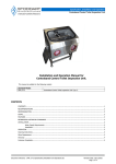
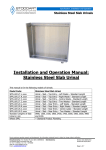
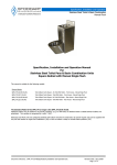
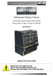
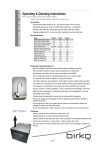
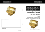
1
Specification, Installation and Operation Stainless Steel Toilet & Basin Combination Units With Electronic Flush Valves Specification, Installation and Operation Manual For Stainless Steel Toilet Pans & Basin Combination Units With Electronic Flush Valves This manual is suitable for the following models: Standard Square Models: SPPL.TP.CS.NT.FA.ED Toilet & Basin Combi Square – No Toilet Roll Holder - Front Access - Electronic Dual Flush SPPL.TP.CS.T.FA.ED Toilet & Basin Combi Square - Toilet Roll Holder - Front Access - Electronic Dual Flush SPPL.TP.CS.NT.RA.ED Toilet & Basin Combi Square - No Toilet Roll Holder - Rear Access - Electronic Dual Flush SPPL.TP.CS.T.RA.ED Standard Round Models: Toilet & Basin Combi Square - Toilet Roll Holder - Rear Access - Electronic Dual Flush SPPL.TP.CR2.R35.T.RA.ED Toilet & Basin Combi Round Type 2 - Pan Right@35 - Toilet Roll Holder - Rear Access - Electronic Dual Flush SPPL.TP.CR2.R35.T.LSA.ED Toilet & Basin Combi Round Type 2 - Pan Right@35 - Toilet Roll Holder - Left Side Access - Electronic Dual Flush SPPL.TP.CR2.L35.T.RA.ED Toilet & Basin Combi Round Type 2 - Pan Left@35 - Toilet Roll Holder - Rear Access - Electronic Dual Flush SPPL.TP.CR2.L35.T.RSA.ED Toilet & Basin Combi Round Type 2 - Pan Left@35 - Toilet Roll Holder - Right Side Access - Electronic Dual Flush SPPL.TP.CR2.R45.T.RA.ED Toilet & Basin Combi Round Type 2 - Pan Right@45 - Toilet Roll Holder - Rear Access - Electronic Dual Flush SPPL.TP.CR2.R45.T.LSA.ED Toilet & Basin Combi Round Type 2 - Pan Right@45 - Toilet Roll Holder - Left Side Access - Electronic Dual Flush SPPL.TP.CR2.L45.T.RA.ED Toilet & Basin Combi Round Type 2 - Pan Left@45 - Toilet Roll Holder - Rear Access - Electronic Dual Flush SPPL.TP.CR2.L45.T.RSA.ED Toilet & Basin Combi Round Type 2 - Pan Left@45 - Toilet Roll Holder - Right Side Access - Electronic Dual Flush SPPL.TP.CR2.C90.T.RA.ED Toilet & Basin Combi Round Type 2 - Pan Centre@90 - Toilet Roll Holder - Rear Access - Electronic Dual Flush SPPL.TP.CR2.C90.T.BSA.ED Toilet & Basin Combi Round Type 2 - Pan Centre@90 - Toilet Roll Holder - Both Side Access - Electronic Dual Flush SPPL.TP.CR2.C90.NT.BSA.ED Toilet & Basin Combi Round Type 2 - Pan Centre@90 - No Toilet Roll Holder - Both Side Access - Electronic Dual Flush SPPL.TP.CR2.L90.T.RA.ED Toilet & Basin Combi Round Type 2 - Pan Left@90 - Toilet Roll Holder - Rear Access - Electronic Dual Flush SPPL.TP.CR2.L90.T.RSA.ED Toilet & Basin Combi Round Type 2 - Pan Left@90 - Toilet Roll Holder - Right Side Access - Electronic Dual Flush SPPL.TP.CR2.R90.T.RA.ED Toilet & Basin Combi Round Type 2 - Pan Right@90 - Toilet Roll Holder - Rear Access - Electronic Dual Flush SPPL.TP.CR2.R90.T.LSA.ED Toilet & Basin Combi Round Type 2 - Pan Right@90 - Toilet Roll Holder - Left Side Access - Electronic Dual Flush (Each of these models is available in optional Heavy Duty variant with “.HD” added to end of product code.) Document reference : SPPL-TP-Cx-ED-Specification,Installation and Operation.doc Revision Date: 24/11/2010 Page 1 of 9 Specification, Installation and Operation Stainless Steel Toilet & Basin Combination Units With Electronic Flush Valves CONTENTS CONTENTS ...................................................................................................................................................................... 2 RECOMMENDATIONS ....................................................................................................................................................... 3 RESPONSIBILITIES........................................................................................................................................................... 3 SCOPE ............................................................................................................................................................................. 3 FEATURES ....................................................................................................................................................................... 3 REFERENCED AUSTRALIAN STANDARDS ........................................................................................................................... 3 INSTALLATION OF PRODUCT............................................................................................................................................ 4 Requirements.................................................................................................................................................... 4 Installation of Toilet Pan and Basin Combination Unit .......................................................................................... 4 Electronic Flushing Device (Purchased with Combi Unit or Separately) .................................................................. 4 Description ............................................................................................................................................ 4 Function ................................................................................................................................................ 4 Supplied with the Sanitron WC Electronic Dual Flush Valve EDFV-01 are the following components............. 4 Safety Precautions for Sanitron valves..................................................................................................... 5 Installation of a Sanitron Electronic Flushing Device (when not factory fitted inside unit) ....................................... 5 Rough-in ............................................................................................................................................... 5 Fit out ................................................................................................................................................... 5 In Duct Installation ................................................................................................................................ 6 Valve Head Assembly ............................................................................................................................. 7 Trouble Shooting ................................................................................................................................... 7 Hydraulic conditions required at the flush valve. ...................................................................................... 7 Spare Parts EDFV-01 .............................................................................................................................. 7 Description ............................................................................................................................................ 9 Function ................................................................................................................................................ 9 Safety Precautions for Sanitron valves..................................................................................................... 9 Installation of the Sanitron bubbler valve................................................................................................. 9 Warranty ......................................................................................................................................................................... 9 Cleaning Instructions ........................................................................................................................................................ 9 Customer Complaints........................................................................................................................................................ 9 Document reference : SPPL-TP-Cx-ED-Specification,Installation and Operation.doc Revision Date: 24/11/2010 Page 2 of 9 Specification, Installation and Operation Stainless Steel Toilet & Basin Combination Units With Electronic Flush Valves RECOMMENDATIONS Upon receiving a Stoddart product, inspect immediately for any visible signs of shipping damage and notify the carrier immediately. When removing the product from its packing, be careful not to dent or scratch outer surface. Any concealed damage should be noted and reported immediately to the freight carrier. A claim should be filed with carrier if appropriate. RESPONSIBILITIES Stoddart thoroughly inspect all products before they are despatched from our factory. Stoddart Manufacturing will not accept responsibility for shipping damage. The Plumber is responsible to ensure that the system is installed in accordance with all specific requirements of local codes and regulations (including AS 3500). If questions or complications should arise during the installation of a Stoddart product that cannot be solved using the accompanying instructions, please contact our offices or local representatives. Note: It is the responsibility of the plumber to install this product in accordance with AS3500. SCOPE This product is designed to be used in institutions and public facilities where vandalism resistance and/or security is required. The product is manufactured to the requirements of AS1172.1 and associated reference standards. The product incorporates a toilet pan and basin in one combined unit. The toilet pan and basin are pushbutton operated. The product is manufactured as a “P trap” design with a rear water inlet. P-S converters are commercially available for applications requiring S trap sewer connection. FEATURES Fully shrouded stainless steel pan. Fully welded seamless outer construction. Secure access panels Flushing volume tested with specific flushing devices to achieve 4.5/3 litre flush. Integral hand basin. Suicide resistant design REFERENCED AUSTRALIAN STANDARDS Markings & Labels Unit Marking to include Maker’s Name, Model identification, Watermark, License No & Flushing volume Installation & Maintenance Manual to state valve manufacturers name / model to be used in a matched performance set Pan Materials Pan Outlet Dimension Pan Water Seal Pan Tests Dezincification resistance Contamination of water Pipes and Fittings Joints (i.e. Spigots, sockets, flanges, or other joint components, where interfacing other authorized components) Flushing Valve Installation Wash Basin Copper alloy products marked ‘DR’ Stainless Steel Shall comply with the applicable clauses Shall comply with the applicable clauses Shall comply with the applicable clauses Dezincification resistance applicable to copper alloy components in contact with mains water Products For Use In Contact With Drinking Water Dimensional compliance with relevant or corresponding Australian Standard for the pipe or fitting Dimensional compliance with relevant or corresponding Australian Standard for the pipe or fitting Pipe Threads of Whitworth Form. – Part 2 Fastening Pipe Threads Shall comply with AS 5200.020 Warranty / Installation instructions shall be provided by the manufacture Shall comply with the applicable clauses Document reference : SPPL-TP-Cx-ED-Specification,Installation and Operation.doc AS 1172.1–2005 Section 4 + AS 5200.000 – 2006 Appendix B + AS 6400 - 2005. Clause 2.4.6 AS AS AS AS AS 1172.1 - Clause 1172.1 - Clause 1172.1 - Clause 1172.1 - Clause 2345 - 2006 5.3 2.2.3 2.1 3.1-3.8 inclusive AS 4020 - 2005 AS 3688 - 2005 AS 3688 - 2005 AS 5200.020 - 2004 AS3500.2 - 2003 AS/NZS 1730-1996 Revision Date: 24/11/2010 Page 3 of 9 Specification, Installation and Operation Stainless Steel Toilet & Basin Combination Units With Electronic Flush Valves INSTALLATION OF PRODUCT Requirements All Stoddart Toilet & Basin Combination Units fitted with an electronically operated flush valve require the following; Flow to the flush valve face must be 1.0-1.5 litres/sec. Operating (dynamic) water pressure must be 250kPa minimum. Static-line pressure must not exceed the limits of the specified valve. It is recommended to install a water filter to protect the flushing valve. A 240V, 10A GPO must be located in an accessible area to power the valve & controllers. Water supply connection for bubbler valve must be 15mm diameter. Water supply connection for flush valve must be 20mm diameter. Installation of Toilet Pan and Basin Combination Unit All Stoddart Toilet pan and basin combination units are supplied with mounting holes pre-punched for easy installation. Remove the packing. Remove the access panels from the Combi unit. Locate the in the correct position & set level. Check the alignment of the toilet connection pipes. Mark the mounting hole positions onto the floor and wall. Remove the Combi Unit. Prior to installing flush valves, flush the water lines first. Connect actuator button wires and solenoid wires to the controller Test flush valve discharge to bucket & set timer to deliver correct volume of water. Install M10 fixing bolts in the wall and secure the Z-clip to floor. Fit the furnco flexible coupling to the sewer discharge pipe. Fit the key seal to the inlet pipe. (The entire key seal is to be inside the flush pipe when toilet is in position). Fit a 40mm PVC trap to the Combi Unit basin outlet. Position the toilet in the correct location whilst coupling the toilet waste to the sewer discharge pipe. Tighten the flexible coupling fasteners and the wall mounting bolts. Connect the 40mm basin trap to the 40mm sewer discharge pipe. Connect the flush valve to water supply, test & check for leaks. Connect bubbler valve to water supply, test & check for leaks. Tighten all fasteners. Apply “no-pick” sealant around base and wall. Test Flush mechanism and check for leaks. Fit and secure access panels. Clean stainless steel surfaces. Note: Protect the product by wrapping in plastic until all other work is complete and the system ready to be put into operation. Electronic Flushing Device (Purchased with Combi Unit or Separately) Approved Models:- Sanitron WC Electronic Dual Flush Valve Art. No. EDFV-01 (Alternative flushing valves and buttons can be paired to these toilets, however no performance testing has been conducted by Stoddart Manufacturing). Description The Sanitron WC Flush Valve Art. No. EDFV-01 is a mains powered (transformer 240V to 12V) Electronic Dual Flush for in ceiling or in-duct installation. Function A user pushes the full or half flush button to activate the flush. Prior to connecting the toilet, the plumber must test the flush volume for the actual line pressure & adjust the time on the flush controller to set the required flush volume. The half flush is adjusted automatically. A new flushing cycle can only be activated after the previous cycle has finished. To prevent misuse and enhance water saving the controller module will allow only a maximum of 6 flushes per minute. Once the valve has been flushed 6 times within one minute the controller will not allow another flush for 45 seconds. Supplied with the Sanitron WC Electronic Dual Flush Valve EDFV-01 are the following components 1 x DFM-01 Electronic dual flush module 1 x TR-1 Transformer 240V to 12Vdc 1 x SV-1 Electronic Flush valve 3m extension cable for actuator buttons Document reference : SPPL-TP-Cx-ED-Specification,Installation and Operation.doc Revision Date: 24/11/2010 Page 4 of 9 Specification, Installation and Operation Stainless Steel Toilet & Basin Combination Units With Electronic Flush Valves Safety Precautions for Sanitron valves The WC Electronic Dual Flush Valve and its components are for indoor use only. Install the WC Electronic Dual Flush Valve and its’ components only in a dry environment. When performing any work WC Electronic Dual Flush Valve or its’ connected components the transformer has to be disconnected from the power supply. The transformer and the electronic module should be installed close to each other. The transformer and the electronic module should be installed as far away from the flush valve as the regulations require. Replace faulty components only with Sanitron original components . For the installation and operation observe all relevant electrical, safety plumbing and building standards. Some equipment may radiates heat do not insulate any supplied equipment. All supplied components should only be used for the purpose they are designed for. Installation of a Sanitron Electronic Flushing Device (when not factory fitted inside unit) Note: All plumbing installation work has to be carried out in accordance with AS/NZS 3500.1 Standard Rough-in Make sure during the planning phase that the proposed installation location (see fig.1&2) for the flush pipe and flush valve is obstruction free (do not install additional bends along the flush pipe other than the bend on the bottom of the flush pipe). Supply a 240 V power point inside the ceiling space or service duct (see fig.1 or 2, also 4 in Safety Precautions above). The cable length of the transformer is about 1.5m Install the DFM-01 electronic module close to the power point (see also 4 in Safety Precautions above). Determine the size and install the water supply pipe to the requirement of the installation (refer to the relevant standards, see also fig.4 page 4 for technical information on the flush valve). Install an appropriately sized ball valve as a stopcock (not supplied). The stopcock should be positioned right next to the flush valve. Install the flush valve and the flush-pipe (40 mm DWV not supplied) in the required location (see also fig.1 or 2). Prior to installing the solenoid valve head onto the flush valve flush the lines first. Remove the cover plate from the flush valve and install the solenoid vale head (see fig.3). Test all plumbing connections for leaks. When the tests are finished close the stopcock. Install the supplied extension cables for the actuator buttons reaching from the DFM-01 module (see fig. 1 or to the installation location of the buttons and secure the cable ends. It is recommended to install the cables in a cable-duct. For in-ceiling installation make provisions for a ceiling access to service the flush valve. Fit out Connect the activator buttons to the extension cable. Connect the extension cables from the buttons and the solenoid valve to the DFM-01 module (see also fig.5). Plug the transformer lead into the DFM-01 module (see also fig.5). Plug the transformer into the power point and switch on the power. Adjust the flush time setting on the DFM-01 module to the active the correct flush volume as outlined in the relevant Australian Standard. The module is pre-set to approximately 5 seconds. o Temporarily connect a measuring bucket to the end of the flush pipe. o Open the flush valve stopcock and activate the full flush. o Compare the collected water volume with Australian Standard requirements. o If too much water is discharged shorten the flush time. With a small screwdriver turn the potentiometer on the controller anti clockwise (see fig.5). o If not enough water is discharged extend the flush time. With a small screwdriver turn the potentiometer on the controller clockwise (see fig.5). o The half flush sets itself automatically. After testing, install the Toilet Combination unit. Activate the valve several times. Check on the valve that there is no water spillage on the airbrake. It is possible that the flush valve will squeak for the first few operations. It is caused by trapped air inside the valve. The squeaking should stop after a few flushes. Note: If the flush valve is activated more than 6 times within one minute it will stop flushing for 45 seconds. Document reference : SPPL-TP-Cx-ED-Specification,Installation and Operation.doc Revision Date: 24/11/2010 Page 5 of 9 Specification, Installation and Operation Stainless Steel Toilet & Basin Combination Units With Electronic Flush Valves In Ceiling Installation In Duct Installation Document reference : SPPL-TP-Cx-ED-Specification,Installation and Operation.doc Revision Date: 24/11/2010 Page 6 of 9 Specification, Installation and Operation Stainless Steel Toilet & Basin Combination Units With Electronic Flush Valves Valve Head Assembly Trouble Shooting Unit will not flush when pressing full or half flush button. Check that the power is switched on, all cable connectors are plugged in and the water is turned on. Check that the solenoid valve head has been assembled the correct way (see fig.3). If the above is correct and unit will not work, unplug the transformer from the power point for a few seconds and than plug it back in. If above checked out o.k. contact service. Unit stopped flushing after several activations. The controller has a build in function that temporarily (45 sec) suspends further flushing once the unit has been flushed more than 6 times within a minute. Wait for 45 seconds, the unit will reset itself or unplug the transformer and re-connect after a view seconds. If above checked out ok. Contact service. Too much flush volume. Shorten the flush time. Not enough flush volume. Lengthen the flush time. Hydraulic conditions required at the flush valve. Min. flow pressure 200 kPa. Min. flow rate 1.4 l/sec Max. flow pressure* 500 kPa Min. connecting pipe size* 25 mm copper Max. static pressure 800 kPa WELS rating 3 STAR * Refers to the minimum connection pipe size to any valve branched off the ring main pipe providing that the above required technical specifications can be met. Pipe work to the valve fixture must be sized to and installed to water service rules and regulations (AS/NZS 3500.1 and local regulations) and simultaneous demand requirements. To ensure proper sizing of the pipe work for the valve it is recommended to engage a qualified hydraulic designer. Spare Parts EDFV-01 Article No Description 101.011 Solenoid valve head complete 100.012 Flush valve bracket 100.013 Plastic funnel with seal 100.014 Funnel fastening nut 100.015 Solenoid cable 100.016 Extension cable for push button 3m 100.017 Extension cable for solenoid valve 1m TR-1 Transformer DFM-01 Dual flush module SV-1 Electronic flush valve Document reference : SPPL-TP-Cx-ED-Specification,Installation and Operation.doc Revision Date: 24/11/2010 Page 7 of 9 Specification, Installation and Operation Stainless Steel Toilet & Basin Combination Units With Electronic Flush Valves Typical installation in combi tower. Document reference : SPPL-TP-Cx-ED-Specification,Installation and Operation.doc Revision Date: 24/11/2010 Page 8 of 9 Specification, Installation and Operation Stainless Steel Toilet & Basin Combination Units With Electronic Flush Valves Electronic Bubbler Valve and Controls Approved Models: Sanitron Electronic Valve Kit EBV-01. Part no.EBV-01 complete with Transformer, Solenoid valve SV-2A, Valve body SV-2B, 1 Piezo button & 2 cables. Description The Sanitron Electronic valve kit is a mains powered (transformer 240V to 12V) electronic valve that supplies water to the bubbler via a piezo button and timer controller. Function A user pushes the button to activate the bubbler. The water flows to the bubbler for the time duration set by the controller. The time duration is adjustable. Safety Precautions for Sanitron valves The Sanitron Bubbler Valve and its components are for indoor use only. Install Sanitron Bubbler Valve and its’ components only in a dry environment. When performing any work Sanitron Bubbler Valve or its’ connected components the transformer has to be disconnected from the power supply. The transformer and the electronic module should be installed close to each other. Replace faulty components only with Sanitron original components . For the installation and operation observe all relevant electrical, safety plumbing and building standards. Some equipment may radiates heat do not insulate any supplied equipment. All supplied components should only be used for the purpose they are designed for. Installation of the Sanitron bubbler valve. Connect the 15mm diameter water supply to the valve. Plug the transformer in to the 240v 10 GPO Press the piezo button to operate the bubbler. Adjust the timer to suit the desired water delivery time. Warranty Upon receiving a Stoddart product, inspect immediately for any visible signs of shipping damage and notify the carrier immediately. When removing the product from its packing, be careful not to dent or scratch outer surface. Any concealed damage should be noted and reported immediately to the freight carrier. A claim should be filed with carrier promptly if appropriate. Stoddart Manufacturing will not accept responsibility for shipping damage. The Standard Terms and Conditions of Sale clearly details Standard Warranty Policy. Plumbing Products offer additional conditions as follows; Warranty on materials and labour is limited to 12 months from date of installation. The Warranty does not cover damage caused by abuse, misuse or improper application or improper installation. Warranty Claims must be submitted in writing to Stoddart Manufacturing within 14 days of observation of fault. Items may be returned to Stoddart’s Factory by the Customer for warranty inspection. For valid warranty claims, Stoddart will repair or replacement the item and return it to the Customer promptly. For installed products, Photos must accompany the Warranty Claim for effective consideration. If a site visit is required to conduct warranty repairs, such work will be carried out during normal business hours e.g. 8am to 5pm. Mon to Fri. Cleaning Instructions All surfaces of the product should be cleaned with mild soap and water or a neutral product. Carefully rinse away all surplus cleaning product. IMPORTANT: Never use harsh or abrasive cleaners on stainless steel. Do not use chlorinated or bleach water Customer Complaints All customer complaints regarding Stoddart Stainless Steel Toilets should be referred to: Customer Service Department Stoddart Manufacturing 149 Jackson Road 4109 Sunnybank Brisbane Ph +61 7 33455011 Fax +61 7 33441000 Email: [email protected] Web : www.stoddart.com.au Document reference : SPPL-TP-Cx-ED-Specification,Installation and Operation.doc Revision Date: 24/11/2010 Page 9 of 9