1
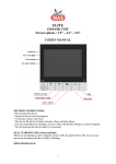
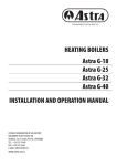
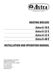
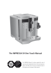
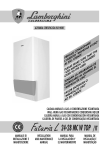
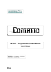
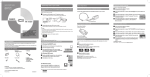
ASTRA MACHINERY PLANT AB • ANNO 1929
Astra P-7
USER MANUAL
CONTACT INFORMATION:
MACHINERY PLANT “ASTRA” AB
ULONŲ G. 33, LT-62161 ALYTUS, LITHUANIA
TEL.: +370 315 75449
E-MAIL: [email protected]
WWW.ASTRA-GAS.LT
TABLE OF CONTENTS
1. SAFETY REQUIREMENTS...................................................................................................4
2. INTENDED USE................................................................................................................4
3. TECHNICAL DESCRIPTION.................................................................................................5
• Components of the Stove............................................................................................................................................5
• Technical Features.......................................................................................................................................................6
• Circuit Diagram...........................................................................................................................................................7
4. FUEL..............................................................................................................................8
5. PLACEMENT, ASSEMBLY AND INSTALLATION.......................................................................8
• Considerations for Placement of the Stove..................................................................................................................8
• Patterns of Installation................................................................................................................................................9
6. TRANSPORTATION, STORAGE, UNPACKING........................................................................12
7. OPERATION..................................................................................................................13
• Display and the Remote Control................................................................................................................................13
• Navigating the Menu................................................................................................................................................14
• Menu Structure.........................................................................................................................................................15
• Setting the Clock.......................................................................................................................................................15
• Setting the Weekly Timer Programs..........................................................................................................................15
• Setting the Room Temperature.................................................................................................................................17
• Output Power Regulation..........................................................................................................................................17
• Regulation of the Room Ventilator............................................................................................................................18
• Setting the Fuel Options...........................................................................................................................................18
• Modifying the Setup Options....................................................................................................................................18
8. MAINTENANCE AND CLEANING........................................................................................19
• Cleaning Schedule....................................................................................................................................................19
• Exterior Surfaces Cleaning........................................................................................................................................20
• Heat Exchanger Tubes Cleaning ................................................................................................................................20
• Ashes Drawer Cleaning.............................................................................................................................................20
• Combustion Chamber Cleaning.................................................................................................................................21
• Fire Pot Cleaning.......................................................................................................................................................21
• Vermiculite Plates Cleaning.......................................................................................................................................21
• Flame Trape Cleaning................................................................................................................................................21
• Flue Channels Cleaning.............................................................................................................................................23
• Pellet Hopper Protection against Burning.................................................................................................................23
• Protective Handle......................................................................................................................................................24
9. TROUBLESHOOTING.......................................................................................................24
• Alerts........................................................................................................................................................................24
• Errors........................................................................................................................................................................25
• Power Supply Failure.................................................................................................................................................25
10. WARRANTY TERMS AND CONDITIONS.............................................................................26
11. ACCEPTANCE CERTIFICATE.............................................................................................26
SELLING CARD..................................................................................................................26
STOVE INSTALLATION PROTOCOL.........................................................................................26
WARRANTY AND POST-WARRANTY REPAIR CARD..................................................................27
DECLARATION OF CONFORMITY..........................................................................................28
3
Astra P-7 USER MANUAL
1. SAFETY REQUIREMENTS
The stove must be installed and tested by qualified personnel instructed and authorized by Astra representing company. Please carefully
read this use and maintenance manual before installing and putting the stove into operation. For further information, please contact your
local Astra dealer.
During the operation of the stove, strictly observe the following safety requirements:
•The stove is designed to be fuelled exclusively with high-quality wood pellets with a diameter of 6 mm as described in chapter 4 of
this user’s guide;
•Do not attempt to operate the stove using traditional wood!
•To avoid potential fire hazards, the stove should not be used for incineration of household garbage under any circumstances!
•Before placement of the stove, check with local building codes to assure that the installation will comply with applicable technical
and legal norms;
•Installation of the stove and the electrical connections, initial function checks and adjustments must be performed by qualified and
authorized personnel;
•Improper installation or poor maintenance (not compliant with instructions of this user manual) may endanger surrounding property
and/or human health. In the case of the aforementioned product misuse, Astra is exempted of civil and criminal responsibility;
•When linking the stove to a flue, all ducting works must be completed prior to connecting to the electrical supply;
•There must be sufficient air circulation in the room where the stove is installed;
•To avoid a potential fire hazard, never open the door of the stove while burning goes on!
•To assure maximum safety while using your stove be sure to follow all use and maintenance operations as described in this manual;
•This pellet stove should not be operated by people with physically or mentally challenging conditions, or who have no experience
using such devices, unless they are under the direct guidance of a qualified and responsible person;
•The stove must not be operated or played with by children;
•To avoid a potential fire hazard, never operate the stove with its door open, or if the door glass is cracked;
•While the stove is in operation, its surfaces, the glass, the door handle and flue ducting become very hot. Use extreme caution and
be sure to use heat-resistant personal protective equipment when touching these components;
•Kindle the stove only after the daily inspection described in this manual has been performed;
•To avoid a potential fire hazard, do not dry laundry on or near the stove. Keep clothes and other flammable objects at a sufficient
distance from the stove;
•For greatest safety, carefully follow the cleaning and maintenance schedule listed in table on page 19 of this manual;
•Do not turn off the stove by unplugging it from the electrical supply;
•Do not clean the stove until a body and ashes have cooled down completely;
•Do not remove the protection grid out of the pellet hopper;
•To avoid the risk of electric shock, do not touch the stove while barefoot and wet;
•The stove must be connected to the electrical supply with an easily accessible plug;
•Do not modify the design of the stove;
•Do not wait for components of the stove to become totally worn before replacing them. Replace a worn component before it
is completely disabled to prevent possible accidents caused by the sudden breakdown of the components. Perform periodic
maintenance checks as described in chapter 8 of this manual.
This stove has been designed to function in all climatic conditions. In the circumstances of particularly adverse weather (high wind,
freezing), safety systems may automatically engage and switch off the stove. If this occurs, please contact technical assistance for
directions. In any case, do not disable the safety systems.
2. INTENDED USE
The Astra pellet stove is an effective home heating appliance intended to heat a room with hot blown air. It simultaneously performs
the function of a fireplace as you view the fire through the temperature-resistant glass. It can be installed in all kinds of residential spaces
where people work, relax or spend their time. In order to reduce any possible danger to human health and property, the stove Astra is
equipped with special safety devices. For added convenience, control of the appliance can be fully automated. Once programmed, the
Astra pellet stove is capable of maintaining different heating output levels at a variety of pre-set time intervals over the course of a day,
4
Astra P-7 USER MANUAL
seven days a week; it sustains a set air temperature in the room with the help of an integrated temperature sensor; and it even makes the
decision to stop the appliance if unfavourable safety conditions arise: draught of the flue disappears or has fallen substantially, the door
of the stove is opened during the operation; the pellet hopper heats up; or other potentially harmful events happen. In addition, the stove
can be operated by a remote control unit (available by special order).
Only 6 mm wood pellets are used for fuelling the Astra stove. The appliance is not designed to be operated with any other kind of fuel
because other fuels leave a greater content of ashes and slag. The latter then will cause the fire pot to clog, activating emergency stop of
the appliance. In order to enjoy the pleasant heat of the stove without unpleasant interruptions, use only high-quality 6 mm wood pellets
and keep the combustion chamber, fire pot and flue channels of the stove cleaned at all times.
3. TECHNICAL DESCRIPTION
• Components of the stove
Wood pellets from the hopper 4 are transported by means of the auger 5 into the fire pot 19 (Fig. 1). The electrical igniter 18 kindles
the pellets. The flame and hot flue gases rise to stainless steel heat exchanger 1, descend afterwards by two lateral flue channels
1
2
3
4
20
5
6
7
19
8
9
18
17
10
11
16
12
13
15
14
Fig. 1 Components of the stove
1. Stainless steel heat exchanger; 2. Flame trap; 3. Display unit; 4. Pellet hopper; 5. Auger; 6. Temperature sensor of the hopper
safety thermostat; 7. Room ventilator; 8. Gear motor; 9. Air intake pipe; 10. Air intake flow sensor; 11. Control board; 12. Hopper
safety thermostat; 13. Smoke exhaust pipe; 14. Room temperature sensor; 15. Pressure sensor; 16. Exhaust fan; 17. Smoke
temperature sensor; 18. Electrical igniter; 19. Fire pot; 20. Heat exchanger tubes scraper.
5
Astra P-7 USER MANUAL
surrounding the combustion chamber and are released with help of exhaust fan 16 into the chimney connection pipe 13. The room
ventilator 7 draws air from surroundings and blows it through the hot heat exchanger tubes 1, thus supplying heat.
• Technical Features
Our product is manufactured in accordance with the following directives:
2006/95/EC– Low voltage directive;
2006/42/EEC – Machinery directive;
2004/108/EEC– Electromagnetic compatibility directive;
89/106/EEC – Construction products directive.
The following standards were applied for the Astra P-7 pellet stove:
EN 14785 – Residential space heating appliances fired by wood pellets;
EN 60335-1 – Safety of household and similar electrical appliances;
EN 60335-2 – Safety particular requirements for fuel burning appliances having electrical connections;
EN 55014-1; EN 55014-2; EN 61000-3-2; EN 61000-3-3 – Electromagnetic compatibility.
Model of the stove Astra P-7
Heat transfer medium Air
Rated heating output 7.8 kW
Reduced heating output 2.6 kW
Period of complete burning of one full fuel load, min-max 9-30 hrs
Weight 85 kg
Height 910±10 mm
Width 453 mm
Depth 500 mm
Flue gas pipe diameter 80 mm
Air intake pipe diameter 35 mm
Capacity of the pellets hopper 15 kg
Fuel: wood pellets 6 mm
Hourly fuel consumption, min-max 0,5-1,6 kg
Heated space volume 150 m3
CO emission level (at 13% O2)
Reduced output
Rated output
0,04 %
0.019 %
Efficiency 85 %
Minimum chimney draught 10 Pa
Average smoke temperature
Average electrical power consumption
(without igniter)
Reduced output
145 °C
Rated output
185 °C
Reduced output
Rated output
60 W
100 W
Rated voltage 230 V
Rated frequency 50 Hz
6
Astra P-7 USER MANUAL
• Circuit Diagram
The electrical circuit diagram of the stove is presented below in Fig. 2. The denomination of elements is as follows:
T1 – Room temperature sensor; T2 – Smoke temperature sensor; B1– Electrical (250 W) igniter; M1 – Fan 1- smoke exhaust fan;
M2 – Fan 2- room ventilator; M3 – Auger gear motor; SK1– Pellet hopper safety thermostat; SK2 – Differential pressure sensor;
F1 – Air flow sensor.
6.3mm
0.5-1.5mm²
4.8mm
0.5-1.5mm²
F1
LCD
ø4mm
0.5-1.5mm²
User interface
T1
T2
t°C
t°C
ø5mm
0.5-1.5mm²
13
15
14
GND F03 F01/02 +VIO
GND I02
CN4
T03
Green
12
White
0.5-1.5mm²
White
Green
6.3mm
0.5-1.5mm²
Braun
Service socket
ø4mm
4-6mm²
17
18
16
T02
T01
CN8
CN10
PE
+
-
Fuse: T 4A
Mainboard
Battery
CN1
CN7
CN5
L
O02
O01
N
L
8
N
9
10
CN9
O04
O03
11
1
2
3
I01
4
7
5
L
6A
L
PE N
S1
1
Black
N
Red
N1
Blue
L1
2
3
4
L1
N1
7
5
8
B1
1
9
M1
M2
2
7
P
6
3
1
SK1
M3
1
Fig. 2 Circuit diagram of the stove.
2
2
SK2
P
3
2
1
Astra P-7 USER MANUAL
4. FUEL
The wood pellets are made from sawdust and wood shavings. The materials used for production of the wood pellets cannot contain
any unnatural components, for example, synthetic glue or paint. The density of the wood pellet varies according to the type of wood
and can be 1.5 – 2 times greater than that of conventional wood. The diameter of cylindrical rods is 6-10 mm and their length can vary
between 10 and 50 mm. Their weight is equal to about 650 kg/m3. Due to the low content of humidity (5-10%) wood pellets have
high energy content.
Do not put a bag of pellets on the surface
DIN 51731 standard defines the quality of wood pellets:
of the stove during the loading operations!
Length
10-50 mm
The pellets must be transported and stored in a dry place. They
Diameter
6 - 10 mm
swell after contact with moisture and become unsuitable for
Weight
650 kg/m3 firing. The pellets must always be protected against humidity
Calorific value
4.9 kWh/kg both during transportation and storage.
Residual humidity
6-12%
Astra strongly advices using the 6 mm diameter
Ashes content
<1.5%
wood pellets for fuelling the Astra stove.
Specific weight
>1.0 kg/dm3
5. PLACEMENT, ASSEMBLY AND INSTALLATION
•Considerations for Placement of the Stove
The residential space considered for the placement of the stove must meet the following technical requirements:
•Pipe connection to a chimney of 8 cm diameter must be installed;
•The supply of air for combustion must be assured either from other ventilated rooms through opening of at least 100 cm2, or directly
from outside through the 35 mm air intake pipe;
•The permanent humidity of air in the room must not exceed 80%;
•A connection of electrical supply of 230V, 50 Hz must be installed;
•CE compliant earthing system must be present.
The placement of the stove is important for the successful heating of the room. Please, take into account the next considerations
before deciding where to place the stove:
•If the supply air needed for combustion is to be taken from another room, that room must be ventilated or have air inflow from
outside. The stove can consume up to 40 m3 of air per hour at maximum, so the sufficient amount of it must be supplied either from
outside or from another inner space of a house;
•The stove cannot be placed in the bathroom, near a shower or bath, or in another space with high humidity level;
•If wooden flooring is present in the desired place of installation, first cover it with a protective fire-resistant plate made from steel,
glass or ceramic;
•The room in which the stove is to be placed must have at least 30 m3 of volume;
•It is recommended to place the stove in the largest room of a house or in a room which has good connectivity with other inner spaces
of a house, so that the maximum circulation of heat would be ensured;
•Connection to the electrical supply must be done through a grounded socket. If the cable of the stove is not long enough to reach the
nearest socket, use a grounded extension cable;
•If another heating installation (stove, fireplace) without autonomous air supply is present in the room of considered placement of the
Astra stove, evaluate, whether there would be a sufficient air supply for both appliances working simultaneously and if that kind of
double installation is allowed by local technical regulations;
The stove must be installed and assembled only by qualified personnel.
•The stove must be placed so that easy access to it and to a chimney is ensured.
•The joints of chimney pipes must have temperature resistant gaskets in order to ensure sufficient tightness of the connections;
•A separate chimney is mandatory for the Astra stove installation. It is not permitted to connect the stove to a shared flue;
•The connection of the air intake tube of the stove to an outside is not obligatory. If the air for combustion is taken from inner spaces
8
Astra P-7 USER MANUAL
of the house, these must be ventilated so that up to 40 m3 of air inflow is ensured;
•Do not use a mesh on the top of a chimney because it can reduce draught and cause problems for the stove functioning;
•When designing the chimney piping for the stove, do not use more than 3 pieces of 90° bends. The biggest distance between the
adjacent bends must not exceed 2,5 meters horizontally;
•If the stove is installed near non-flammable walls, a minimum distance of 10 cm should be left from the rear stove panel to the wall.
This distance must be increased to 20 cm, if the wall is covered with flammable finish. In either case, a 50 cm free space must be left
from lateral sides of the stove and 150 cm- from the front side. It is recommended to increase the mentioned distances further, if
NO
YES
very easily flammable objects likeYES
curtains are present in the vicinity of the stove.
FIG.9
FIG.6
FIG.10
• Patterns of installation
Yes
Chimney cap for rain protection
G.9
FIG.6
S
NO
Insulated flue
This type of installation (Fig. 3) requires an
insulated flue, as the whole smoke pipe is
installed outside the house. A chimney tee with
an inspection cap and condensate drain pipe is
mounted in the lower part of the flue.
FIG.10
YES
Insulated chimney tee with
condensation drain pipe
Fig. 3 Chimney installed outside the house.
No
A 90° bend should not be installed as the first
connecting part – ashes would quickly obstruct a
passage for smoke causing unexpected problems
for draught of the flue (Fig 4).
Ashes accumulate in the 90° bend
Fig. 4 Incorrect installation - with 90° bend as the first connecting part.
9
FIG.5
YES
FIG.6
FIG.10
NO
FIG.5
Astra P-7 USER MANUAL
YES
FIG.
YES
NO
Chimney cover plate
This type of installation (Fig. 5) does not require
an insulated flue as the smoke pipe is assembled
partly inside the house and partly inside an
existing flue. A chimney tee with a peephole cap
is installed in the lower part of the flue.
Please note the use of two 45° bends in order
to guarantee that ash falls into the chimney tee
with the cap and the peephole.
Airtight steel sheeting
Yes
45° bend, Ø 80 mm
10
FIG.5
Chimney tee with a cap and a
peephole
FIG.8
FIG.7
Fig. 5 Smoke
YES pipe installed partly inside a house and partlyNOinside an existing flue.
S
Yes
Chimney cap for rain
protection
This type of installation (Fig. 6), does not require
an insulated flue, because the whole smoke pipe
is assembled inside a house. A chimney tee with a
peephole is mounted in the lower part of the flue.
Chimney tee with a cap and a
peephole
Fig. 6 Whole smoke pipe installed inside a house.
10
YES
Astra P-7 USER MANUAL
2500
ma
No
Two 90° bends cannot be assembled the
way shown in Fig. 7, because ashes would
quickly obstruct a passage for smoke causing
unexpected problems for draught of the flue.
H > 4000 mm
H > 1500 mm
Ashes accumulate in the 90° bend
FIG.8
NO
FIG.7
Fig. 7 Incorrect installation with two 90° bends.
YES
Yes
Chimney cap for rain
protection
2500 mm.
max.
H > 4000 mm
H > 1500 mm
Insulated flue
Insulated chimney tee with
condensation drain pipe
Chimney tee with a cap and a
peephole
Fig. 8 Installation with a combined internal/external flue.
This type of installation (Fig. 8) does not require an insulated flue for the part inside the house, whereas for the outside part an
insulated tube must be used. A chimney tee with a peephole is installed in the lower part of the flue inside the house. Another
chimney tee is installed in the outside part of the flue making it available for inspection.
Sufficient draught is essential for the efficiency of all chimneys. Draught arises from temperature differences inside and outside of
the chimney, which consequently cause pressure differences.
Weather and geographical conditions such as wind, snow, rain, altitude above sea level, fog, etc., can also have an impact on chimney
draught. Among them, wind is certainly the most important. Wind generally increases draught except in cases of downdraughts,
11
Astra P-7 USER MANUAL
temperature inversions, or cross draughts caused by tall trees, hills, or buildings in close proximity to the chimney. These situations
can cause the smoke to be pushed back DOWN the chimney.
The installation, placement, and design of the chimney have a direct influence on the stove’s functioning. Any negative influence
of installation can be compensated for by reprogramming the stove controller.This adjustment must be done by qualified service
personnel.
2500 mm.
1
max.
2
Insulated flue
12
3
4
5
H > 4000 mm
H > 1500 mm
8
9
Insulated chimney tee with
6
condensation drain pipe
10
11
7
Chimney tee with a cap and a
peephole
Fig. 9 Recommended lengths of parts of a combined internal/external flue
The minimum height of chimney from the stove’s smoke pipe to the chimney top is 4 meters. The recommended lengths of various
parts of combined internal/external flue are presented in Fig. 9.
6. TRANSPORTATION, STORAGE, UNPACKING
The stove is to be transported and packaged in original packaging of the manufacturer, protected from precipitation and dust. It
must be transported only in the vertical position, fastened to avoid sliding and falling. If the stove is transported any other way,
decorative surfaces may be damaged, cladding battered, control and regulation equipment broken, or the fire pot may fall down and
harm the vermiculite plates. The appliance should be carefully loaded, unloaded and transported, to avoid any significant impact.
The stoves can be loaded one on the top of another, because the packaging is designed so that the stoves may be transported and
stored in two decks. However, loading other objects on the top is prohibited as the packaging frame of the stove has been designed
specifically to support the same stove.
The stove should also be stored in a vertical position, in a closed room protected from precipitation. The air humidity of the room
should not exceed 80%, in order to avoid condensate forming on the surfaces of the appliance. Storage temperatures may vary from
-40 °C to +60 °C. If the stove was transported or stored in sub-zero temperatures, then it should be moved to a place above zero for
no less than 2 hours before being used.
After the stove is delivered to the site, take off the packing frame and polyethylene film, remove the stove from the packaging base.
Then check if all elements listed in a delivery kit are included. The delivery kit consists of the following: stove - 1 pc.; cable with plug
for electrical connection - 1 pc.; fire pot - 1 pc.; protective handle - 1 pc.; user manual - 1 pc.; remote control (only when ordered
separately) - 1 pc.
The user manual is an integral part of the stove. Please, make sure that it remains with the stove, including
cases when it is transferred to another user or another place.
12
Astra P-7 USER MANUAL
Check to ensure that painted surfaces have not been damaged during transportation, that the components are not bent, and that
the control and regulation equipment is intact. If you notice any damage or discrepancies, present your claims to the vendor company.
7. OPERATION
• Display and Remote Control
The remote control unit does not come in a standard delivery kit of a stove. It must be ordered separately.
The Astra stove controller consists of two parts: a display and a control board mounted near the base of the stove. The
display operates by principle of capacitive touchscreen. Pushing buttons on it requires good contact with the fingertip rather than
force. Therefore, the display will not react if gloves are worn while attempting to use the controller.
3
4
5
6
7
8
9
10 11 12 13
1
2
14
18
19
15
1
17
16
Fig. 10 Display and the remote control unit.
1. Start/stop button; 2. Cancel/return button; 3. No fuel indicator; 4. Cleaning required indicator; 5. Servicing required indicator; 6. IR
sensor; 7. Weekly timer indicator; 8. Burning power menu indicator; 9. Room ventilator speed menu indicator; 10. Temperature menu
indicator; 11. Fuel quality menu indicator; 12. Time menu indicator; 13. Setup menu indicator; 14. Edit buttons; 15. Enter button; 16.
Menu buttons; 17. Screen; 18. Burning power +/- buttons; 19. Temperature +/- buttons.
Button
Description
This button is used to start and stop the combustion process in the stove. The process is launched or stopped by
pressing the button and holding it for 1 second.
Menu buttons are intended to navigate horizontally the controller menu (look at the menu structure tree
presented below). The chosen section of the menu is indicated in the upper line of indicators on the display.
Edit buttons are used for two purposes: vertical navigation (look at the menu tree) and increasing/decreasing
parameter values in the edit mode, when the selected value blinks.
Enter button is used for entering the edit mode, confirming the set parameter values or entering the lower menu
levels.
Cancellation button is used for discarding the made changes and returning up one level in the menu. If you press
and hold this button for more than 3 seconds, the last error or alert code will be displayed.
The infrared remote control is intended for day-to-day use when the combustion system is fully configured and operational. It is used
for changing the burning power and temperature settings, turning the combustion in the stove on and off.
In the upper part of the display, there is a line of indicators signaling various modes and alerts of the controller. The IR sensor in that
line is used for communication with remote control unit.
13
Astra P-7 USER MANUAL
The screen displays the set or current values for the currently selected menu option. Buttons help to navigate through the menu and
control different functions of the stove controller. The intended use of the buttons is described in the table above.
The display has an integrated beeper. The beeper generates feedback signals, when the display buttons are being pressed. The
following sound signals are available:
• Short high tone: sounds when navigating the menu and editing the settings.
• Long low tone: sounds in case of an invalid operation (wrong button pressed).
• Long high tone: in case of an alert, this tone sounds with the user-defined volume; in case of an error, this tone sounds at 100%
volume; for description of alerts and errors, refer to the chapter “Troubleshooting”.
• Navigating the menu
In order to navigate the menu horizontally, in the same level, use the menu buttons
. When choosing a menu option, an icon
in the indicator line of the display lights up. At the same time, the screen indicates either the value of the chosen menu parameter, or,
in the case the chosen menu section has a sublevel (for example, Time menu), the value of the first subsection parameter.
. When navigating the lower sublevel of the menu, a number
In order to navigate the menu vertically, use the menu buttons
of a particular menu subsection briefly lights up. For example, the Time menu section has a lower level menu consisting of four
subsections. Each time you skip to the next subsection the number from 1 to 4 lights in the screen.
To modify a setting in the menu, press button to enter the edit mode for the selected setting. The screen value starts blinking.
buttons to change the value. To move through the steps in the edit mode, use
. buttons. When finished, press
Use
button to save the setting and exit the edit mode. The display returns to the menu entry you have just edited.
The screen of the display shows the set value or the actual measured value, depending on the setting. For example, when you edit
the temperature, you enter the desired room temperature. After you exit the edit mode, the screen indicates the actual measured
temperature which may differ from the set temperature. When you edit, for example, the burning power setting, the screen indicates
the set value.
To exit the edit mode without saving the changes, press button. This button is also used for returning up one level in the menu.
For example, if you are editing the Program 3 in the Weekly Timer Periods menu subsection, press the Cancel button to discard the
changes and return to Program 3. Pressing the Cancel button further moves you to Weekly Timer Periods, then - to the Clock menu
section.
Power
Burning power
Fan
Fan speed
Temperature
Room
temperature °C
Fuel
Time
Setup
Fuel quality
pellets
Clock
Time/Date
Key lock
Idle display
brightness
Weekly timer
days
Weekly timer
ON/OFF
Idle display
mode
Weekly timer
periods
Beeper volume
Monday
Tuesday
Wednesday
Program 1
Service menu
Thursday
Program 2
Friday
2. Program
1. Program
Saturday
Program 3
Sunday
Program 4
Fig. 11 Menu structure
14
Start time
End time
Temperature
Astra P-7 USER MANUAL
• Menu structure
The menu structure tree (Fig. 11) exhibits all consisting menu entries. The values of parameters are chosen for purpose of illustration
only. The buttons used to reach a particular menu entry are depicted near it.
• Setting the clock
The controller enables you to set the current time, date and weekly timer programs. These settings do not disappear even after power supply
failure because the controller has a long-lasting battery. To look up at the current time, press
button to enter the Time menu section.
The current time is indicated on the screen
. To turn to the other Time menu subsections, use
buttons. The numerical
value from 1 to 4 will shortly light up in the screen, when passing each subsection.
Clock and date setting mode. Press
With
Press
With
Press
With
button and change the desired values.
buttons set the desired hour.
With
Press
.
buttons set the desired day.
With
Press
.
buttons set the year value. Press
buttons set the minutes value.
.
buttons set the month value.
.
.
• Setting the weekly timer programs
Weekly timer activation. Press
button and enter the edit mode. With
buttons choose the desired value.
Weekly timer is switched off.
Weekly timer is switched on. The icon
in the indicator line lights permanently.
The first step in weekly timer programming is to describe the time intervals- programs. The description consists of specifying the
interval start time, the end time and the desired temperature. Then, the desired programs are assigned to each day of a week. The
controller permits you to create up to 6 different timer programs and to assign a maximum of 3 of them to each day of the week. The
programs with start time in one day and end time in the next day are also allowed. When the weekly timer is active, the icon in
the indicator line lights permanently.
Creating and editing the weekly timer programs. Press
buttons to skip to another programs for editing.
First program. Press
button and enter the first program edit mode. Use
button and enter the desired values.
With
buttons set the start time value. Press
With
buttons set the end time value. Press
.
.
With
buttons set the desired temperature of the program. Press
confirmation.
Second program. Press
button and enter the desired values.
With
buttons set the start time value. Press
15
.
for
Astra P-7 USER MANUAL
With
buttons set the end time value. Press
.
With
buttons set the desired temperature of the program. Press
confirmation.
(the third, fourth, fifth programs are skipped for the purpose of illustration)
Sixth program. Press
for
button and enter the desired values.
With
buttons set the start time value. Press
With
buttons set the end time value. Press
.
.
With
buttons set the desired temperature of the program. Press
confirmation.
for
Assigning programs to week days. This is performed after the programs have been created (see above). Press
buttons skip to another week days for editing.
button and enter the Monday edit mode. With
Monday. 3 different programs can be assigned to each day of a week. Press button
and enter the desired values. If only 2 programs are planned for a particular day,
choose option OFF for one of the entries.
With
buttons set the desired program number. Press
.
With
buttons set the desired program number. Press
.
With
buttons set the desired program number. Press
for confirmation.
Tuesday. 3 different programs can be assigned to each day of a week. Press button
and enter the desired values. If only 2 programs are planned for a particular day,
choose option OFF for one of the entries.
With
buttons set the desired program number. Press
.
With
buttons set the desired program number. Press
.
With
buttons set the desired program number. Press
for confirmation.
(Wednesday, Thursday, Friday, Saturday are skipped for the purpose of illustration)
Sunday. 3 different programs can be assigned to each day of a week. Press button
and enter the desired values. If only 2 programs are planned for a particular day,
choose option OFF for one of the entries.
With
buttons set the desired program number. Press
.
With
buttons set the desired program number. Press
.
With
buttons set the desired program number. Press
for confirmation.
If two programs with overlapping operation time are assigned to the same day of the week, the controller,
during the overlap period, performs the program with higher title number. For example, program P6 will
have priority against P3.
16
Astra P-7 USER MANUAL
An example of created programs is presented in the table below:
P1 Program
P2 Program
P3 Program
On Off
23:00 4:30
16°C
On Off
4:30 7:30
19°C
On Off
17:00 23:00
19°C
P4 Program
P5 Program
P6 Program
On Off
00:00 7:30
16°C
On Off
7:30 24:00
19°C
On Off
7:30 23:00
16°C
The above mentioned programs are displayed in the time intervals diagram:
Day/Time
1 2 3 4 5 6 7 8 9 10 11 12 13 14 15 16 17 18 19 20 21 22 23 24
[P1] 16°C
[P2] 19°C
[P3] 19°C
(d1) Monday
[P1] 16°C
[P2] 19°C
[P3] 19°C
(d2) Tuesday
[P1] 16°C
[P2] 19°C
[P3] 19°C
(d3) Wednesday
[P1] 16°C
[P2] 19°C
[P3] 19°C
(d4)Thursday
[P1] 16°C
[P2] 19°C
[P3] 19°C
(d5) Friday
[P4] 16°C
[P5]19°C
(d6) Saturday
[P4] 16°C
[P6] 19°C
(d7) Sunday
• Setting the room temperature
The stove is capable of sustaining the desired room temperature. It has a room temperature sensor for that purpose. The sensor must
be placed as far from the stove as its cord allows. The stove reacts to indications of the sensor and increases the heating power after
the air in the room has cooled down. When the temperature in the room rises, the stove decreases the heating power or even stops.
There are two ways to set the desired room temperature:
• use weekly timer programs;
• set the room temperature manually.
When using weekly timer, you describe time intervals for each day of a week and assign the desired temperatures to them. For more
information about time programing see the previous chapter Setting the Weekly Timer Programs.
It is also possible to set the desired room temperature manually. If a weekly timer program is active at the same time, the manually
set room temperature temporary gains priority. This priority disappears, when the current weekly timer program ends. When the next
time program starts, the room temperature again is controlled by the weekly timer.
To view a current room temperature, press
button to enter the Temperature menu section. The actual measured room
temperature value is indicated on the screen.
Actual measured room temperature.
To set the desired room temperature, press
or decrease this value with
buttons.
. button. The screen indicates the target temperature in the blinking mode. Increase
Target temperature value blinks.
When finished, press button for confirmation. The actual measured room temperature is indicated on the screen again.
The room temperature can be set and changed with remote control as well. It is treated by the controller the
same as a manual setting.
• Output power regulation
The output power defines the maximum burning power level which will be used by the stove to heat the ambient air. There are six
power levels:
. The stove increases burning power by raising
a rotations quantity of pellet transporting auger per time period and the quantity of supplied air for combustion simultaneously.
Thus, more pellets and more air are supplied to the burning pot. If the target room temperature is set, the stove chooses the optimal
burning power level itself. You can interfere with this process and set, for example, a higher power level if you want the stove to
achieve the target room temperature faster. When your goal is to decrease the consumption of pellets, you can diminish the burning
power level. In either case, the stove lowers the burning power level itself for better economy, after the target room temperature has
17
Astra P-7 USER MANUAL
been achieved. By default, when you do not set the power level manually the stove controller returns to the automatic power mode.
Then the symbol
shows on the screen.
To view the burning power setting, press
button to enter the Power menu section. The current power level value is indicated
on the screen. If fastest possible room heating is required, set the burning power on the highest level
.
The burning power level can be set and changed with remote control as well.
• Regulation of the room ventilator
The controller enables you to change the rotational speed of the room ventilator. There are six levels of the speed:
. We recommend you to let the stove itself decide upon the rotational
intensity. For this option, the speed setting
must be chosen. The optimal stove control principle requires that a user of the
stove would rather set a desired room temperature with weekly timer or manually and let the stove to decide itself which burning
power and rotational speed levels are most appropriate in the given situation.
• Setting the fuel options
The Fuel menu section enables you to select the fuel quality. The quality of pellets are expressed in the following values:
. These values stand for the moisture content in pellets. The dryer the fuel, the higher fuel value in this menu
section must be chosen.
The fuel quality option in this stove is deactivated. The fuel value 1 is set irreversibly.
• Modifying the setup options
The Setup menu section enables you to set the options for Key lock, Idle display brightness, Idle display mode, Beeper volume and
view service information.
The Key lock option enables you to lock the keyboard on the display in order to prevent accidental changes of the
settings. With the key lock enabled, you can navigate the menu to display current values, but you cannot edit any
of the settings, except the Key lock itself. Note that this option does not disable the remote control. The Key lock
setting offers the following options:
The Key lock is disabled, all buttons are operational.
The edit mode is disabled. The Enter button is locked.
The edit and the power on/off modes are disabled. The Enter button and the Power button are locked.
We recommend using the Key lock option, when cleaning the display.
The display brightness in the idle mode can be set from 1 to 5 or set to turn off after 30 seconds.
The display switches off after 30 seconds. The lighting is restored after pressing any button.
Brightness of the display is 1.
...
...
Brightness of the display is 5.
18
Astra P-7 USER MANUAL
The Idle display mode has the following options:
The display stays in the last selected menu section. In case the menu has been in the edit mode, the changes are
discarded and the edit mode is exited.
The display exits the last selected menu section and cycles between a current room temperature and a clock.
<->
The display exits the last selected menu section and moves to the Temperature menu. The actual measured room
temperature is displayed on the screen.
The display exits the last selected menu section and moves to the Time menu. The current time is indicated on
the screen.
Beeper volume setting enables the user to change the volume of the display signals from 1 to 5 or switch the
beeper off.
The beeper is off.
The sound level is 1.
...
...
The sound level is 5.
The controller information menu subsection. Used for service purposes.
Version of the controller main board.
Version of the controller display.
The service menu subsection. Access for the authorized service personnel only.
The random 4-digit number combination is indicated on the screen.
button to enter the Setup menu section. The set idle display brightness value is displayed.
To modify the setup options, press
To move between the setup options, press
buttons to display the settings. To change a setting, press button and use
buttons to increase/decrease the selected values. When finished, press button to confirm the set value.
8. MAINTENANCE AND CLEANING
Regular cleaning is of crucial importance for the continued operation of the stove. Failure to follow the cleaning schedule, or the use
of dirty fuel can clog the inner spaces of the stove. These impurities can hinder air supply to the combustion chamber and cause the
stove to stop working. To prevent this outcome, it is highly recommended that the user perform the cleaning activities specifically as
described in the following chapters.
• CLEANING SCHEDULE
Tasks/ Frequency
Fire pot cleaning
Ashes drawer emptying
Door glass cleaning
Flame trap cleaning
Exchanger tubes scraping
Combustion chamber vacuuming
Pellet hopper vacuuming
Flue channels cleaning
Door gasket changing
Chimney cleaning
Daily
Once per 2-3 days
o
o
o
o
o
o
19
Once per 30 days Once per 60-90 days Once per season
o
o
o
o
Astra P-7 USER MANUAL
Before starting cleaning works, make sure that:
• The electrical supply switch on the rear panel of the stove is OFF;
• All stove components and ashes have cooled down sufficiently;
• Suitable tools will be used for cleaning;
• The electrical cable is unplugged when flue channels are to be cleaned.
When cleaning the combustion chamber, be careful and do not clog the pressure sensor’s pipe which
is mounted inside, on the left wall of the chamber, under a vermiculite plate. The pipe must remain
unobstructed.
The frequency of maintenance and cleaning depends directly on the quality of pellets used. Burning high quality pellets allows
you to devote less time and attention to cleaning activities, and to increase the periods between cleanings. Vice versa, bad quality
pellets will require shorter intervals between cleaning
tasks. The quality of the pellets and a sound adjustment
1
of combustion are essential to the reliable operation of
the stove.
2
The pellet stove is a generator of heat and technically
sophisticated appliance. Therefore, we strongly
recommend servicing by qualified personnel at least
3
once a year, at the start of the heating season to ascertain
and ensure the continued function and efficiency of all
the stove's components.
• EXTERIOR SURFACES cleaning
To clean the surfaces on the painted metal parts, use a
cloth slightly moistened in water. If necessary, mild soap
may also be used. Rub the surfaces gently and with care.
Do not use any aggressive detergents
or solvents – they can cause serious
damage to the surfaces of the stove. Do not scrub
excessively the metal paint - the structured paint
surface changes its shading because of rubbing
impact.
4
• Heat exchanger tubes cleaning
Fig. 12 Frequently inspected elements and their locations.
1. Scraper; 2. Combustion chamber; 3. Fire pot; 4. Ashes drawer.
The heat exchanger is composed of stainless steel
tubes. Smoke flows constantly around the outer surface
of the tubes leaving soot residues on them. These
residues must be removed every 2 days of operation. For
this purpose, inside the heat exchanger there is a scraper
which brushes the tubes' surfaces like a comb. Pull the
handle of the scraper 1 ( Fig. 12) towards yourself. To
complete the cleaning session, push and pull this handle
till halting several times.
• Ashes drawer cleaning
The ashes drawer must be cleaned daily or every 2 days,
depending on the length of time the stove is used and
the quality of pellets used. To access the ashes drawer,
open the door, remove the ashes drawer 4 (Fig. 12) and
empty it.
Fig. 13 Clean fire pot. No residue
inside, all the holes clean and
visible.
20
Fig. 14 Pot with the holes
blocked by ashes. Cleaning
required.
Astra P-7 USER MANUAL
•Combustion chamber cleaning
Clean the combustion chamber every 2 days. Use a drum-type vacuum cleaner for cleaning the combustion chamber. Make sure
that no ashes are left after the cleaning session.
• Fire pot cleaning
A clean fire pot is of essential importance to assure uninterrupted stove operation.
During the combustion process, increments of ashes and slag fill up the holes of the
pot (Fig. 14). These increments must be removed immediately because they block the
air flow. Inspect the holes frequently and make sure that the holes on the bottom as
well as those on the sides of the pot are clear and fully open (Fig. 13). Failure to keep
these holes clear leads to clogging, reducing the air supply and finally to automatic
shut-off of the stove.
Timely and scrupulous cleaning of the fire pot prevents problems that in the longer
term could require the intervention of a technician to repair the stove.
Fig. 15 Vermiculite plates kit.
• Vermiculite plates cleaning
The combustion chamber of the Astra pellet stove is lined with three vermiculite plates (Fig. 15). Vermiculite has high resistance to
heat, is lightweight and has excellent insulation properties. All these features ensure good combustion and effective performance of
the stove.
During the combustion process, the vermiculite plates turn white giving the flame clear and shining look. When combustion is
regulated properly, the surface of these plates remains clean and white. Thus, the plates act as indicator – a light colour indicates that
the combustion quality is high, a dark colour signals that combustion quality is poor.
•Vermiculite plates do not require any specific maintenance. Gentle cleaning with a brush to remove any ash residue is all that is
necessary.
•Do not use any abrasive sponges to clean the most resistant spots – they could diminish the thickness of the vermiculite plates thus
creating critical points that may result in cracking.
•Do not use any wet cloths to clean the plates.
•Do not use the tube of a vacuum cleaner in direct contact with the vermiculite plates. Work keeping the tube’s head withdrawn at
a safe distance from the plates.
Vermiculite is resistant to heat. However, it
is fragile and not resistant to knocks. Please,
do not exercise strength; handle it with care when
moving.
1
Slight abrasion can appear on the vermiculite plates after a few hours
of firing. This is absolutely normal as the flame creates microgrooves
in the surface of the plates without imposing considerable damage.
The lifetime length of the vermiculite plates depends only on how
2
carefully their maintenance is performed.
Clean the vermiculite plates only after they
have cooled down. Use a vacuum cleaner to
remove the ashes.
• Flame trap cleaning
The flame trap must be taken out and cleaned every 2 days.
Perform this procedure after the stove cools down completely.
Fig. 16 presents the sequence of the flame trap removal.
The flame trap is located inside the combustion chamber, in its Fig. 16 Removing the flame trap.
top part. It rests on two supports – the front and the rear one. 1. Rear support; 2. Front support.
21
Astra P-7 USER MANUAL
Fig. 17a
Fig. 17b
Fig. 17 Removing the top cover of the stove.
Fig. 18a
Fig. 18 Opening the inspection hatches of the flue channels.
22
Fig. 18b
Astra P-7 USER MANUAL
Grasp the flame trap; pull it towards yourself until the lower part of the trap gets loose. Then, pull down it, remove the flame trap
from the chamber and clean. When done, work in the opposite sequence to place it back.
• Flue channels cleaning
The flue channels must be cleaned from combustion approximately once every three months. This period strongly depends upon
the quality of wood pellets. For this type of cleaning, it is recommended to consult with the technician who has installed the stove.
Use a drum-type vacuum cleaner only.
The flue of the stove has two channels: at the left and at the right side of the combustion chamber. These channels join together into
one smoke passage box near which the exhaust fan 16 (Fig. 1) is mounted. To access the inspection hatches of the flue channels, both
lateral panels and top cover of the stove must be removed. Before removing the top cover of the stove, the display has to be taken out
and disconnected. Work in the following order:
1. Remove the frame of the display. Using thin vertical screwdriver, locate two gaps in the left and the right side of the plastic frame
of the display. Turn the screwdriver inside those gaps, gently separate the frame from the display (Fig. 17a).
2. Take out the display. Use a PH1 size cross
screwdriver to unscrew four screws fastening the case
of the display. Lift the display (Fig. 17a).
The display is connected to the
controller board by RJ11 type data
cable. Do not forget to disconnect the cable
before taking out the display.
3. Remove the rooftop cover. Unscrew six M5 bolts
in the top rear side of the stove: three on the left
and three on the right side (Fig. 17b). Push the cover
towards the rear panel of the stove until its holders
get loose (Fig. 17). Then lift the cover and remove it.
4. Remove the lateral panels of the stove. Unscrew
bolts fastening the panels near the front grates at the
top part of the stove (Fig. 18a) and in the front and
the rear sides of the base plate of the stove. Raise the
panels and remove them (Fig. 18).
5. Open all four the inspection hatches. Unscrew
pairs of M5 bolts, remove gaskets and inspection lids
(Fig. 18b). Clean the flue channels in both sides of the
stove.
• Pellet hopper protection
against BURNING
1
2
The pellet hopper has a protection from overheating
and burning: the temperature sensor 6 and the
thermostat 12 (Fig.1). They operate independently
from the controller. If for any reason the hopper
starts overheating the thermostat stops the stove by
interrupting the electrical supply.
To restart operation of the stove, remove the
thermostat cover 2 (Fig. 19) and depress the button
behind it.
Fig. 19 1. Protective handle; 2. Safety thermostat.
23
Astra P-7 USER MANUAL
• Protective handle
There is a place on the rear panel of the stove projected for hanging a protective handle 1 (Fig. 19). It is intended to prevent direct
contact of human hands with hot surfaces of the stove when doing maintenance. Use this handle as a tool, when pulling the scraper’s
handle out of the front grate and for other actions that require touching hot surfaces and elements of the stove.
9. TROUBLESHOOTING
The stove display provides warnings for alerts and errors which can occur during the operation of the controller. The alarm icons
in the indicator line of the display signal a problem. An alert notification is indicated by blinking icons, errors are indicated with
continuously lit icons. In case of an alert, the combustion system remains operational. In case of an error, the combustion system has
malfunctioned seriously and is disabled. To solve the problem, a service technician should be contacted.
Each alert and error has a code which can be used to identify the problem. To display the code, press and hold the Cancellation button
for 3 seconds. If there is no information on the alert/error code, the screen shows ----.
• Alerts
No fuel
Indication:
Icon No fuel is
blinking
Code: ----
Cause: When the fuel in the hopper runs out, the Solution: Refill the pellets hopper.
notification is triggered. The combustion system turns Delete the alert by pressing and holding
off and cannot be restarted.
the Start/stop button on the display.
Combustion chamber or chimney is dirty
Indication:
Icon Cleaning is
blinking
Indication:
Icon Cleaning is
blinking
Code: A003
Code: ----
Cause: The combustion chamber or the chimney are
dirty and require cleaning. There is too much ash or
unburned pellets in the combustion chamber; and/or
the chimney is congested with soot.
Solution: Inspect and empty the
combustion chamber or contact
service personnel to sweep the
chimney.
Low battery
Indication:
Icon Service is
blinking
Code: A004
Cause: The controller battery gets discharged. The Solution: Contact service personnel to
change the controller battery. Do not attempt
combustion system is still operational.
to change the battery on your own.
Fan 1 – the exhaust fan- speed sensor failure
Indication:
Icon Service is
blinking
Code: A005
Cause: The speed sensor of the exhaust fan is Solution: Contact service personnel.
malfunctioning. The combustion system is still
operational.
Pressure sensor failure
Indication:
Icon Service is
blinking
Code: A007
Cause: The pressure sensor has malfunctioned. The Solution: Contact service personnel.
combustion system is still operational.
Regular maintenance required
Indication:
Icons Service
and Cleaning is
blinking
Code: A002
Cause: The time to the next service has run out. If set up by Solution: Contact service personnel.
service personnel, the Time to service counter counts time
in hours in the reverse direction. When this counter reaches
zero, the Service icon starts blinking. This value is read-only
and can be modified by authorized personnel only.
24
Astra P-7 USER MANUAL
Remote control battery empty
Indication:
Remote control is
not responsive
Cause: The battery of the remote control is empty. The
remote control uses the CR2025 or CR2032 battery.
Solution: Replace the battery. Refer
for the instructions to the back side
of the remote control unit.
• errors
Service required
Code
Indication:
Icon Service lights E001: Keyboard error
E002: IR communication error
constantly
E003: RF communication error
E004: MB communication error
E101: Fire error
E105: NTC2 error
E106: NTC3 error
E107: TC2 error
E108/109: Security switch or Pressure switch error
E110: NTC1 error
E111: TC1 error
E112: Pellets hopper overheating error
E115: General error
Cause: The combustion
system has malfunctioned
and not operational.
Solution: note the error
code and contact service
personnel.
Cause: Certain information
stored in the controller
is updated to the display
at startup moment, for
example, configuration data.
An unexpected error appears
on the screen when making
changes to the controller
settings.
Solution: disconnect and
then reconnect the display
to reset it. If the problem
persists, contact service
personnel for support.
Unspecific errors on the display
Indication:
Unknown error is displayed on the screen
Icon Service lights
constantly
• Power supply failure
During power supply failure, the
controller remains active due to internal
battery. Its internal status remains as it
was before the power failure. Internal
electronics runs in power saving mode
consuming very little amount of energy.
In case of the power supply failure, the
controller operates as follows:
Duration of power
supply failure
Operation before the
power supply failure
Operation after the power supply
failure
Fire up phase
The controller continues normally.
The controller checks the flue gases
temperature and continues in the Burning
phase or restarts in the Fire Up phase.
Remains OFF.
The controller continues normally.
The controller checks the flue gases
temperature. If the flue gases
temperature dropped below some
setting (PAR56), the combustion system
restarts in the Fire Up phase, otherwise
it continues in the Burning phase.
Remains OFF.
Less than 1 minute Burning phase
OFF phase
Fire Up phase
More than 1
minute
Burning phase
OFF phase
25
Astra P-7 USER MANUAL
10. WARRANTY TERMS AND CONDITIONS
The manufacturer provides a warranty for the stoves, the main conditions of which are the following:
• the installation of the stove as well as the initial kindling, adjustment and repairs are carried out by an authorised company;
• the stove is installed and operated following the requirements of this operation manual;
• the client presents this operation manual with validated selling card form in it;
• the duration of the warranty period for the stove is 24 months with the exceptions of the below presented components;
• the warranty does not apply for the following components of the stove:
- vermiculite plates;
- door glass;
- gaskets;
- ignition element.
• the warranty repairs are performed when the fault has occurred due to the manufacturer’s fault;
• damages originated from transportation, careless storage and handling will not be covered by the warranty. The claims for such
kind of damages should be presented to the vendor company;
• the warranty term is not extended after removing the faults which have occurred during the warranty period;
• cleaning of the stove and installation works are not covered by the warranty;
• the damage caused to the premises and the property in the premises, human health due to the stoves fault will not be compensated;
• the warranty repair works and replacement of parts during the warranty period are free;
• the warranty period starts from the stove purchase date;
• all the warranty obligations of the manufacturer are listed in this chapter; the manufacturer cannot be held responsible for
additional obligations undertaken by third parties.
11. ACCEPTANCE CERTIFICATE
The stove Astra P- 7, serial No. ................................., conforms to the technical documentation, requirements of the standard EN
14785 and is approved as fit for operation.
Manufacturing date 201 ................................................................
L. S.
Head of Quality Service ..................................................................
SELLING CARD
Pellet stove sold by:
Company: ..............................................................................................................................................................................................
Address: .................................................................................................................................................................................................
Telephone: .............................................................................................................................................................................................
Date of sale: ...........................................................................................................................................................................................
Signature: ..............................................................................................................................................................................................
STOVE INSTALLATION PROTOCOL
Pellet stove installed by:
Company (Technician): ...........................................................................................................................................................................
Address: .................................................................................................................................................................................................
Telephone: .............................................................................................................................................................................................
Installation date: ...................................................................................................................................................................................
26
Astra P-7 USER MANUAL
Installation data:
Height of the chimney: ...........................................................................................................................................................................
Diameter of the flue: ...............................................................................................................................................................................
Draught of the chimney: ........................................................................................................................................................................
Other information concerning installation: ............................................................................................................................................
...............................................................................................................................................................................................................
...............................................................................................................................................................................................................
The pellet stove was tested on site, the control and safety elements were checked and found to be operating properly.
Person responsible for installation and testing: ......................................................................................................................................
(Name, surname, signature of the employee)
I accept the installation works: ...............................................................................................................................................................
(Name, surname, signature of the employee)
WARRANTY AND POST-WARRANTY REPAIR CARD
Pellet stove repaired by:
Company (technician): ...........................................................................................................................................................................
Address: .................................................................................................................................................................................................
Telephone: .............................................................................................................................................................................................
Repair date: ...........................................................................................................................................................................................
Information on fault, works performed: ................................................................................................................................................
...............................................................................................................................................................................................................
...............................................................................................................................................................................................................
...............................................................................................................................................................................................................
Signature of the technician: ...................................................................................................................................................................
27
Astra P-7 USER MANUAL
DECLARATION OF CONFORMITY
LT
Manufacturer: Machinery plant “Astra” AB.
Address: Ulonu g. 33, 62161 Alytus, Lithuania.
Product designation: pellet stove Astra P-7.
Our product is manufactured in accordance with the following directives:
2006/95/EC– Low voltage directive;
2006/42/EEC – Machinery directive;
2004/108/EEC– Electromagnetic compatibility directive;
89/106/EEC – Construction products directive.
The following standards were applied for the Astra P-7 pellet stove:
EN 14785 – Residential space heating appliances fired by wood pellets;
EN 60335-1 – Safety of household and similar electrical appliances;
EN 60335-2 – Safety particular requirements for fuel burning appliances having electrical connections;
EN 55014-1; EN 55014-2; EN 61000-3-2; EN 61000-3-3 – Electromagnetic compatibility.
Viktoras Bondarevas
Head of Heating Products Division
AB machinery plant Astra
28