1
IS23SC4439 User Manual
IS23SC4439 User Manual
Integrated Silicon Solution, Inc.
Copyright Notice and Proprietary Information
Copyright © 2005 Integrated Silicon Solution, Inc. All rights reserved. This documentation is owned by Integrated
Silicon Solution, Inc., and furnished under a license agreement. The documentation may be used or copied only in
accordance with the term of the license agreement. No part of the documentation may be reproduced, transmitted, or
translated, in any form or by any means, electronic, mechanical, manual, optical, or otherwise, without prior
permission of Integrated Silicon Solution, Inc. or as expressly provided by the license agreement.
ISSI Confidential
Version 1.1
July 13, 2006
IS23SC4439 User Manual
Table of contents
1.
Features .....................................................................................................................................4
2.
General Description ..................................................................................................................4
3.
Typical Transaction Time .........................................................................................................4
4.
RF Coil Specification................................................................................................................4
5.
Functional Description ..............................................................................................................5
5.1 Block Description................................................................................................................5
5.2 Communication Principle....................................................................................................5
5.2.1 REQUEST / REQUEST ALL......................................................................................6
5.2.2 ANTICOLLISION LOOP............................................................................................6
5.2.3 SELECT CARD ...........................................................................................................6
5.2.4 TRIPLE PASS AUTHENTICATION .........................................................................7
5.2.5 MEMORY OPERATIONS..........................................................................................7
5.3 Command Set ......................................................................................................................7
5.3.1 COMMAND TABLE...................................................................................................7
5.3.2 STATE MACHINE......................................................................................................8
5.3.3 COMMAND DESCRIPTION .....................................................................................8
5.3.3.1 Request Standard..............................................................................................8
5.3.3.2 Request All.......................................................................................................8
5.3.3.3 Anti-collision....................................................................................................9
5.3.3.4 Continue Anti-collision....................................................................................9
5.3.3.5 Select Card .......................................................................................................9
5.3.3.6 Authen A|B.......................................................................................................9
5.3.3.7 Read................................................................................................................10
5.3.3.8 Write...............................................................................................................10
5.3.3.9 Halt.................................................................................................................11
5.3.3.10 Decrement/Increment ...................................................................................11
5.3.3.11 Restore..........................................................................................................12
5.3.3.12 Transfer ........................................................................................................12
5.4 Data Integrity ....................................................................................................................13
5.5 Security .............................................................................................................................13
ISSI Confidential
Version 1.1
July 13, 2006
IS23SC4439 User Manual
5.6 RF Interface.......................................................................................................................13
5.7 Memory Organization .......................................................................................................14
5.7.1 MANUFACTURER BLOCK ....................................................................................14
5.7.2 DATA BLOCK ..........................................................................................................15
5.7.3 SECTOR TRAILER (BLOCK 3) ..............................................................................15
5.8 Memory Access.................................................................................................................16
5.8.1 ACCESS CONDITIONS FOR THE SECTOR TRAILER .......................................16
5.8.2 ACCESS CONDITIONS FOR DATA BLOCKS......................................................17
6.
Characteristics .........................................................................................................................18
7.
Ordering information ..............................................................................................................18
8.
Revision History......................................................................................................................18
FIG. 1 RF COIL ................................................................................................................................... 5
FIG2 BLOCK DIAGRAM ....................................................................................................................... 5
FIG3 COMMUNICATION FLOW ............................................................................................................. 6
TABLE 1 COMMAND SET ..................................................................................................................... 7
FIG. 4 AUTHENTICATION MECHANISM .............................................................................................. 13
TABLE 2 MEMORY ORGANIZATIONS ................................................................................................. 14
TABLE 3 MANUFACTURER BLOCK............................................................................................ 15
TABLE 4 DATA BLOCK.................................................................................................................. 15
TABLE 5 SECTOR TRAILER .......................................................................................................... 16
TABLE 6 MEMORY OPERATIONS ....................................................................................................... 16
TABLE 7 SECTOR TRAILER ACCESS CONDITIONS................................................................. 17
TABLE 8 DATA BLOCKS ACCESS CONDITIONS...................................................................... 18
ISSI Confidential
Version 1.1
July 13, 2006
IS23SC4439 User Manual
1. Features
Contactless transmission of data and
supply energy
Up to 100mm operation distance
13.56MHz operating frequency
106k bit/s date rate
High level security data communication
True anti-collision
1k bytes EEPROM, organized in 16
sectors with 4 blocks of 16 bytes each
User definable access condition for each
memory block
Data retention > 10 years
Write endurance 1,000,000 cycle
typically
Typical ticketing transaction < 100ms
Three pass authentication (ISO/IEC
DIS9798-2)
Data encryption on RF-channel with
replay attack protection
Two keys per sector (per application) to
support multi-application with key
hierarchy
Unique serial number for each device
Transport key protects access to
EEPROM on chip delivery
Conform to ISO/IEC14443A standard
Operation temperature range -25 to
+70C
2. General Description
IS23SC4439 is contactless smart card IC compliant to ISO/IEC 14443A standard with
0.35um CMOS EEPROM process technology. IS23SC4439 has 1k bytes EEPROM. It has
high performance security functions and contactless communication functions. IS23SC4439
can be used in payment card, public transportation card and many other applications.
3. Typical Transaction Time
Identification of a card select: 2.5ms (incl. Answer to Request, Anticollision and Select)
Authentication: 2ms
Read block (16 bytes): 2.5ms (excl. Authentication)
Write block + Control Read: 4ms (excl. Authentication)
Write block: 3.2ms (excl. Authentication)
Increment: 2.5ms (excl. Authentication)
Decrement: 2.5ms (excl. Authentication)
Transfer: 3.2ms (excl. Authentication)
Restore: 2.5ms (excl. Authentication)
Typical ticketing transaction: < 100ms
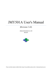
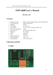
4. RF Coil Specification
ISSI Confidential
Version 1.1
July 13, 2006
IS23SC4439 User Manual
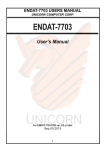
Fig. 1 RF Coil
5. Functional Description
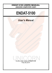
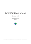
5.1 Block Description
IS23SC4439 chip consists of 1k bytes EEPROM, RF Interface and Digital Control Unit.
Energy and data are transferred via an antenna, which consists of a coil with a few turns
directly connected to IS23SC4439. No further external components are necessary.
Fig2 Block Diagram
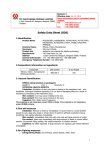
5.2 Communication Principle
The commands are initiated by PCD (Proximity Coupling Device) and controlled by the
Digital Control Unit of IS23SC4439 according to the access conditions valid for the
corresponding sector.
ISSI Confidential
Version 1.1
July 13, 2006
IS23SC4439 User Manual
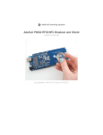
Fig3 Communication Flow
5.2.1 REQUEST / REQUEST ALL
After Power On Reset (POR), PICC can answer to a request command sent by
PCD to all PICCs in the antenna field with ATQA (answer to request) code
according to ISO/IEC 14443A.
5.2.2 ANTICOLLISION LOOP
The serial number of a PICC is read in the anti-collision loop. If there is more than
one PICC in the operating range of PCD, PICCs can be identified by their unique
serial numbers and one of them can be selected for further transactions. The
unselected PICCs return to the standby mode and wait for a new request command.
5.2.3 SELECT CARD
With the ‘Select Card’ command PCD select one PICC for authentication and
memory related operations. PICC returns ATS (Answer To Select) code indicating
the type of the selected PICC to PCD.
ISSI Confidential
Version 1.1
July 13, 2006
IS23SC4439 User Manual
5.2.4 TRIPLE PASS AUTHENTICATION
After selection of a PICC, PCD specifies the memory access locations and use the
corresponding key for the triple pass authentication procedure. After a successful
authentication, all memory operations are encrypted
5.2.5 MEMORY OPERATIONS
After authentication the following operations can be preformed:
Read: Read a block data (16 bytes)
Write: Write a block data (16 bytes)
Decrement: Decrement the contents of a block and store the result in a
temporary internal data-register
Increment: Increment the contents of a block and store the result in the internal
data-register
Restore: Move the contents of a block into the internal data-register
Transfer: Write the contents of the temporary internal data-resister to a value
block
5.3 Command Set
5.3.1 COMMAND TABLE
Command Name
Request Standard
Request All
Anti-collision
Select Card
Authen A
Authen B
Read
Write
Increment
Code
26
52
93 xx
93 70
60 xx
61 xx
30 xx
A0 xx
C1 xx
Decrement
C0 xx
Restore
Transfer
C2 xx
B0 xx
Halt
50 00
Brief Description
Search Idle PICC in field
Search all PICCs in field
Waiting PICC ID feed back
Select PICC
Authentication with keyA
Authentication with keyB
Read a block data (16 bytes)
Write a block data (16 bytes)
Increment the contents of a block and store the
result in the data-register
Decrement the contents of a block and store the
result in a temporary internal data-register
Move the contents of a block into the data-register
Write the contents of the temporary internal dataresister to a value block
Put PICC into halt state
Table 1 Command Set
ISSI Confidential
Version 1.1
July 13, 2006
IS23SC4439 User Manual
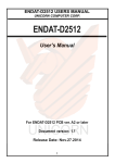
5.3.2 STATE MACHINE
Power
off
Reset
ERROR
Halt
Idle
REQA
WUPA
WUPA
Antico
Ready*
SELECT
ERROR
Ready
ERROR
ERROR
Active
1*
Antico
SELECT
Active
1
AUTHEN
AUTHEN
Active
2*
Active
2
HALT
HALT
5.3.3 COMMAND DESCRIPTION
5.3.3.1 Request Standard
1) ‘Request Standard’ command is executed in Idle state.
2) PCDs send 0x26 LSB 7 bits, without parity bit and CRC.
3) Normally after PICC receives the command “Request Standard” from
PCD, it responds PICC’s TYPE information (byte6 and byte7 of block0)
with parity bit and CRC, the total response is 18 bits, and then PICC
shifts into Ready state and waits for ‘Anti-collision’ command. PICC will
respond nothing and stay at Idle state in case of any errors.
5.3.3.2 Request All
1) ‘Request All’ command is executed in Idle state or Halt state.
2) PCD sends 0x52 LSB 7 bits without parity bit and CRC.
3) Normally after PICC receives the command “Request All” from PCD, it
responds PICC’s TYPE information (byte6 and byte7 of block0) with
parity bit and CRC, the total response is 18 bits, and then PICC shifts into
Ready state and waits for ‘Anti-collision’ command. PICC will respond
nothing and stay at Idle state or Halt state in case of any errors.
ISSI Confidential
Version 1.1
July 13, 2006
IS23SC4439 User Manual
5.3.3.3 Anti-collision
1) ‘Anti-collision’ command is executed in Ready state.
2) PCD sends 0x93 20 with parity bit and without CRC.
3) Normally after PICC receives command from PCD, it responds
UID+BCC (in block0 of sector0) with parity bit and without CRC (45 bits
totally), after that PICC stays at Ready state and wait for ‘Anti-collision’
or ‘Select Card’ command, until the ‘Select Card’ command UID
parameter match the chip UID. PICC will respond nothing and go back to
Idle state in case of any errors
5.3.3.4 Continue Anti-collision
1) ‘Continue Anti-collision’ command is executed in Ready state.
2) PCD sends 0x93, 0xNM, and followed by specified partial UID data with
parity bit and without CRC. Where: N= 2 +(All following UID/BCC byte
number), M= (All following UID/BCC bit number)- 8* (the following
UID/BCC byte number).
3) Normally after PICC receives command from PCD, if PICC UID can
match the specified partial UID followed after the 93NM, PICC responds
the rest UID and BCC data in EEPROM with parity bit and without CRC,
after that stays at Ready state and waits for new anti-collision command.
Otherwise PICC will respond nothing and go back to Idle or Halt state.
Please refer to ISO/IEC 14443-3 for detail process。
5.3.3.5 Select Card
1) ‘Select Card’ command is executed in Ready state.
2) PCD sends 0x93, 0x70, plus all UID+BCC with parity bit and CRC.
3) Normally after PICC receives ‘Select Card’ command, if the 4 bytes UID
and BCC code match chip UID, chip verifies the parity bit and CRC, if no
error found, PICC responds the byte5 of block0 in sector0 to indicate the
EEPROM size with parity bit and CRC, after that PICC goes to Active1
state and waits for the authentication command or Halt command. PICC
will respond nothing and go back to Idle state in case of any errors.
5.3.3.6 Authen A|B
1) ‘Authen A|B’ command is executed in Active 1 state, it includes 2
communication stages, called triple pass authentication process according
to ISO/IEC 9798-2.
The first interactive:
2) PCD sends 0x60|61, 0xXX, where XX is sector and block definition with
CRC and parity bit.
ISSI Confidential
Version 1.1
July 13, 2006
IS23SC4439 User Manual
3) Normally after PICC receives the command 0x60/61 from PCD, PICC
responds 4 bytes random code RB with parity bit and without CRC. If
sector error, PICC responds 4 bits 0x4 error code. If CRC or parity bit
error occurs, PICC responds 4 bits 0x5 error code. If other error occurs
such as received byte does not match 4 bytes, PICC responds nothing.
PICC always goes back to Idle state or Halt state in case of any errors.
The second interactive:
4) PCD sends TokenAB to PICC including 4 bytes RA and 4 byte RB’ with
parity bit and without CRC. After that all information transformed
between PCD and PICC will be ciphered and keep secret.
5) Normally PICC decrypts RA first, and shifts RA into key generator (48bit shifter) with feedback switch closed, then continue to decrypt RB’ and
compare with internal RB’, if they are equal, PICC responds ciphered
random number RB’’ with parity bit and without CRC, after that PICC
will go to Active2 state and wait for new command. PICC will respond
nothing and go to Idle state or Halt state in case of errors.
5.3.3.7 Read
1) ‘Read’ command is executed in Active2 state. The parameter is the block
and sector address of EEPROM. In Active2 state the read access control
condition is determined by the sector trailer byte stored in the block3 of
corresponding EEPROM sector. For block0 of sector0, it is manufacture
block and always can be read in Active2 state. If PCD tries to read
protected block in Active2 state, PICC responds 4 bits error code 0x4 to
PCD and then goes to Idle state or Halt state. If CRC error or parity bit
error occurs, PICC responds 4 bits error code 0x5 to PCD, and returns to
Idle state.
2) PCD sends 0x30, 0xXX with parity bit and CRC.
3) Normally PICC responds EEPROM 16 bytes block data to PCD with
parity bit and CRC, if the block is read protected according to access
condition stored in block3, PICC responds 4 bits error code 0x4, after that
stays at Active2 state and waits for new command. If CRC error or parity
bit error occurs, PICC responds 4 bits error code 0x5. If command is error,
PICC responds nothing, all kind of errors will put PICC into Idle state or
Halt state.
5.3.3.8 Write
1) ‘Write’ command is executed in Active2 state. The parameter is the block
and sector address of EEPROM. In Active2 state the write access control
condition is determined by the sector trailer byte stored in the block3 of
ISSI Confidential
Version 1.1
July 13, 2006
IS23SC4439 User Manual
corresponding EEPROM sector. If PCD tries to write protected block in
Active2 state, PICC responds 4 bits error code 0x4 and goes to Idle state
or Halt state. In the first interactive process, if CRC error or parity bit
error occurs, PICC responds 4 bits error code 0x5 to PCD, in case of
other errors such as sector/block address error or access bit format error
or command error, PICC responds 4 bits error code 0x4 to PCD, after that
PICC goes to Idle state or Halt state. Note: block0 of sector0
(manufacture block) is read only for user in Active2 state. This command
has two interactive processes.
The first interactive:
2) PCD sends 0xA0 and block/sector address to PICC with parity bit and
CRC. All data is ciphered in Active2 state.
3) If the access condition says the block is writable, PICC responds 4 bits ok
code 0xA without parity bit and CRC, then waits for data to be written.
Otherwise, responds 4 bits error code 0x4 and then goes to Idle state or
Halt state. All response is ciphered.
The second interactive:
4) PCD sends 16 bytes ciphered data to PICC with parity bit and CRC.
5) If write is successful, PICC responds 4 bits ciphered ok code 0xA, and
then stays at Active2 state and waits for new command. If parity bit error
or CRC error occurs, it responds 4 bits ciphered error code 0x1. If the
data length is error, PICC responds nothing. All kind of errors will put
PICC into Idle state or Halt state.
5.3.3.9 Halt
1) ‘Halt’ command is executed in either Active1 state or Active2 state. In
Active1 state, command and response is not encrypted, however in
active2 state, it will be encrypted.
2) PCD sends command 0x50 00 to PICC with parity bit and CRC.
3) Once receiving the HALT command correctly in Active1 state or Active2
state, PICC goes to Halt state without any response, and keep waiting for
‘Request All’ command. If parity bit error or CRC error occurs, PICC
responses 4 bits error code 0x5, if command error, PICC responds 4 bit
error code 0x4. All kind of errors will put PICC into Idle state or Halt
state.
5.3.3.10 Decrement/Increment
1) ‘Decrement/Increment’ command is executed in Active2 state. It can be
applied on block0, block1 and block2. The block/sector address will be
the command parameter. The command has two interactive processes.
ISSI Confidential
Version 1.1
July 13, 2006
IS23SC4439 User Manual
2) PCD sends ciphered command 0xC0/C1 and block/sector address to
PICC with parity bit and CRC.
3) If the corresponding block and sector can be increased or decreased,
PICC responds 4 bits OK code 0xA. If the block can not be increased or
decreased, or the access condition byte format error, or block/sector
address error, or command error, or data inc/dec overflow error occurs,
PICC responds 4 bits error code 0x4. If parity bit or CRC error occurs,
error code is 4 bits 0x5. PICC will go back to Idle state or Halt state in
case of any errors.
4) PCD sends 4 bytes ciphered inc/dec data with parity bit and CRC to PICC.
5) If the data format is correct and no error occurs, PICC responds nothing,
then loads the data into buffer and calculates the inc/dec result and keeps
the result in the buffer, after that stays at Active2 state and waits for new
command. If overflow error occurs, PICC responds 4 bits error code 0x4,
if CRC and parity bit error occurs, PICC responds 4 bits error code 0x1.
PICC will go back to Idle state or Halt state in case of any errors.
5.3.3.11 Restore
1) ‘Restore’ command is executed in Active2 state. Block/ sector address
will be the command parameter.
2) PCD sends the ciphered command 0xC2 and block/sector address to
PICC with parity bit and CRC.
3) If the corresponding sector and block can be restored, PICC loads
EEPROM data that PCD indicated in command into buffer, and responds
4 bits ok code 0xA, after that stays at Active2 state and waits for new
command. If the block cannot be restored, or the address error, or
command error, or access condition byte error, PICC responds 4 bits error
code 0x4. If the CRC and parity bit error occurs, PICC responds 4 bits
error code 0x5 to PCD. All kind of errors will put PICC into Idle state or
Halt state.
5.3.3.12 Transfer
1) ‘Transfer’ command is executed in Active2 state. It transfers the data
from internal buffer into EEPROM.
2) PCD sends ciphered command 0xB0 and block/sector address to PICC
with parity bit and CRC. Block/sector address parameter indicates the
destination of transferring to.
3) If the target address block can be transferred, PICC writes the data of
internal buffer into EEPROM, and responds 4 bits OK code 0xA to PCD,
then stays at Active2 state and waits for new command. If the block can
ISSI Confidential
Version 1.1
July 13, 2006
IS23SC4439 User Manual
not be transferred, or address error, or command error, or access
condition byte format error, PICC responds 4 bits error code 0x4. If parity
bit or CRC error occurs, PICC responds 4 bits error code 0x5. All kind of
errors will put PICC into Idle state or Halt state.
5.4 Data Integrity
To ensure reliable data transmission, following mechanisms are implemented in the
contactless communication link between PCD and PICC:
16 bits CRC per block
Parity bits for each byte
Bit count checking
Bit coding to distinguish between "1", "0", and no information
Channel monitoring
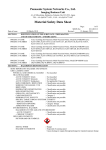
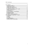
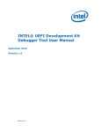
5.5 Security
To provide high secure level, the triple pass authentication according to ISO 9798-2 is
used in the following sequence:
a. PCD specifies the sector to be accessed and chooses key A or B.
b. PICC reads the secret key and access conditions from the sector trailer, then PICC
sends a random number as the challenge to PCD (pass one).
c. PCD calculates the Response using the secret key and additional input. The response,
together with a random challenge from PCD, is then transmitted to PICC (pass two).
d. PICC verifies the response of PCD by comparing it with its own challenge and then
calculates the response to the challenge and transmits it (pass three).
e. PCD verifies the response of PICC by comparing it to its own challenge.
Note: After transmission of the first random challenge the communication between PICC
and PCD is encrypted.
Fig. 4 Authentication Mechanism
5.6 RF Interface
The RF interface conforms to ISO/IEC 14443A standard. The carrier field from PCD is
always present (with short pauses when transmitting). For both directions of data
communication there is only one start bit at the beginning of each frame. Each byte is
ISSI Confidential
Version 1.1
July 13, 2006
IS23SC4439 User Manual
transmitted with a parity bit at the end. The LSB of the byte with the lowest address of the
selected block is transmitted first. The maximum frame length is 163 bits.
5.7 Memory Organization
The 1024 x 8 bit EEPROM memory is organized in 16 sectors with 4 blocks of 16 bytes
each. In the erased state the EEPROM cells are read as a logical "1", in the written state as
a logical "0".
Sector
Block
0 1 2 3 4 5 6 7 8 9 A B C D E F
F
3 Trailer
2 Data
1 Data
0 Data
KeyA
Access bits
KeyB
E
3 Trailer
2 Data
1 Data
0 Data
KeyA
Access bits
KeyB
.
.
.
.
.
.
.
.
.
.
.
.
1
3 Trailer
2 Data
1 Data
0 Data
KeyA
Access bits
KeyB
0
3 Trailer
2 Data
1 Data
0 Data
KeyA
Access bits
KeyB
Manufacture Block
Table 2 Memory Organizations
5.7.1 MANUFACTURER BLOCK
This is the first data block (block 0) of the first sector (sector 0). It contains the IC
manufacturer data. Due to security and system requirements this block is write
protected after having been programmed by the IC manufacturer at production.
MSB
LSB
x x x x
0
0 1 0
ISSI Confidential
Version 1.1
July 13, 2006
IS23SC4439 User Manual
0 1 2 3
Serial Number
4
Check Byte
5
6
7
8 9 A B C D E F
Manufacture Data
Table 3 MANUFACTURER BLOCK
5.7.2 DATA BLOCK
All sectors contain 3 blocks of 16 bytes for storing data (Sector 0 contains only two
data blocks and the read-only manufacturer block).
The data blocks can be configured by the access bits as:
Read/Write blocks for e.g. contactless access control or
Value blocks for e.g. electronic purse applications, where additional commands
like increment and decrement for direct control of the stored value are provided.
An authentication command has to be carried out before any memory operation in
order to allow further commands.
The value blocks allow electronic purse functions (valid commands: Read, Write,
Increment, Decrement, Restore, Transfer). The value blocks have a fixed data format,
which permits error detection and correction and a backup management. A value
block can only be generated through a write operation in the value block format:
Value: Signifies a signed 4-byte value. The lowest significant byte of a value is
stored in the lowest address byte. Negative values are stored in standard 2's
complement format. For reasons of data integrity and security, a value is stored
three times. Twice non-inverted and once invented.
Adr: Signifies a 1-byte address, which can be used to save the storage address of
a block when implementing a powerful backup management. The address byte is
stored four times twice invented and non-inverted. During Increment/ decrement,
restore and transfer operations the address remains unchanged. It can only be
altered via a write command.
Byte
0 1 2 3 4 5 6 7 8 9 A B C
D
E
F
Number
Description
Value
_____
Value
Value
___
___
Adr Adr Adr Adr
Table 4 DATA BLOCK
5.7.3 SECTOR TRAILER (BLOCK 3)
Each sector has a sector trailer containing the secret keyA and keyB (optional),
which return logical "0"s when read and the access conditions for the four blocks of
that sector, which are stored from bytes 6 to byte 9. The access bits also specify the
type {read/write or value} of the data blocks.
ISSI Confidential
Version 1.1
July 13, 2006
IS23SC4439 User Manual
If key B is not needed, the last 6 bytes of block 3 can be used as data bytes.
Byte 9 of the sector trailer is available for user data. For this byte apply the same
access rights as for byte 6, 7 and 8.
Byte Number 0 1 2 3 4 5 6 7 8 9 A B C D E F
Description
KeyA
Access bits
KeyB (optional)
Table 5 SECTOR TRAILER
5.8 Memory Access
Before any memory operation can be carried out, PICC has to be selected and
authenticated as described previously. The possible memory operations for an addressed
block depend on the key used and the access conditions stored in the associated sector
trailer.
Memory Operations
Operation Description
Valid for Block Type
Read
Read one memory block
Value & Sector Trailer
Write
Write one memory block
Value & Sector Trailer
Increment Increment the contents of a block and stores the
Value
result In the internal data register
Decrement Decrement the contents of a block and stores the
Value
result In the Internal data register
Transfer
Write the contents of the internal data register to a Value
block
Restore
Read the contents of a block into the internal data Value
register
Table 6 Memory Operations
5.8.1 ACCESS CONDITIONS FOR THE SECTOR TRAILER
Depending on the access bits for the sector trailer (block 3) the read/write access to
the keys and the access bits is specified as 'never', 'keyA', 'keyB' or 'keyA|B' {keyA
or keyB}.
On chip delivery the access conditions for the sector trailers and keyA are predefined
as transport configuration. Since keyB may be read in transport configuration. New
PICC must be authenticated with keyA.
Since the access bits can also be blocked. Special care should be taken during
personalization of PICC.
Access Control Condition for
Access bits
KeyA
Access bits
KeyB
C1
C2
C3
read
write read
write read
write
0
0
0
never keyA keyA
never keyA keyA
ISSI Confidential
Version 1.1
July 13, 2006
IS23SC4439 User Manual
0
0
0
1
1
1
1
0
1
1
0
0
1
1
1
0
1
0
1
0
1
never
never
never
never
never
never
never
keyA
never
keyB
keyB
never
never
never
keyA
keyA
keyA|B
keyA|B
keyA|B
keyA|B
keyA|B
keyA
never
keyB
never
keyB
never
never
keyA
keyA
never
never
never
never
never
keyA
never
keyB
keyB
never
never
never
Table 7 SECTOR TRAILER ACCESS CONDITIONS
Note: the grey marked lines are access conditions where keyB is readable and may
be used for data
5.8.2 ACCESS CONDITIONS FOR DATA BLOCKS
Depending on the access bits for data blocks (blocks 0...2) the read/write access is
specified as 'never', 'keyA', 'keyB' or 'key A|B' (keyA or keyB). The setting of the
relevant access bits defines the application and the corresponding applicable
commands.
Read/write block: The operations read and write are allowed
Value block: Allows the additional value operations Increment, decrement,
transfer and restore. In one case ('001 ') only read and decrement are possible for
a non-rechargeable PICC. In the other case ('110') modification is possible by
using key B
Manufacturer block: The read-only condition is not affected by the access bits
setting
Key management: In transport configuration key A must be used for
authentication
Access bits
Access Control Condition for
Application
C1 C2 C3 read
write
inc.
dec.
transfer
restore
0
0
0 keyA|B keyA|B keyA|B keyA|B transport
configuration
0
0
1 keyA|B never
never
keyA|B value block
0
1
0 keyA|B never
never
never
read/write block
0
1
1 keyB
keyB
never
never
read/write block
1
0
0 keyA|B keyB
never
never
read/write block
1
0
1 keyB
never
never
never
read/write block
1
1
0 keyA|B keyB
keyB
keyA|B value block
1
1
1 never
never
never
Never
read/write block
ISSI Confidential
Version 1.1
July 13, 2006
IS23SC4439 User Manual
Table 8 DATA BLOCKS ACCESS CONDITIONS
If keyB may be read in the corresponding Sector Trailer, it cannot serve for
authentication (all grey marked lines in previous table).
Consequences: if PCD tries to authenticate any block of a sector with keyB using
grey marked access conditions, PICC will refuse any subsequent memory access
after authentication.
6. Characteristics
PARAMETER
CONDITIONS
Operating frequency
Input capacitance
25C, VCC = 3 V
MIN.
TYP.
MAX.
13.56MHz
16.5 pF
7. Ordering information
Part Number
IS23SC4439-X00MCxxxW
IS23SC4439-X10MCxxxT
Package
Sorted Wafer
Tape & Reel Module
8. Revision History
REV
1.0
Initial Version
1.1
Minor Change
ISSI Confidential
History
Page
---
Version 1.1
Date
11/3/05
7/13/06
July 13, 2006