1
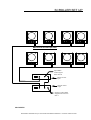
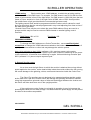
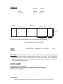
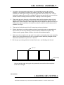
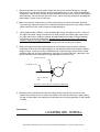
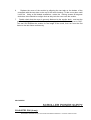
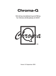
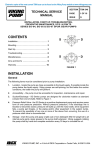
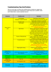
COLOURTEC
COLOUR SCROLLER
COLOURTEC
USER MANUAL
SHOWCRAFT AUSTRALIA Pty Ltd. 937 Bourke Street Waterloo NSW 2017. Document created 21/12/00
COLOURTEC
TECHNICAL DATA
Number of gels: 2-16 colours
Maximum Speed: 0.1 sec per frame
Size: 310mm x 310mm x 70mm
Weight: 1.75 Kg
Colour: Satin Black texture
Construction: Aluminium closed casing
Power: 24vDC 1.2Amp
Control: DMX512 Usitt - All 512 channels
Control channels: One
Scaling: Self detects number of frames for 0-100%
Mechanism: Electronic tensioning and zeroing
Cooling: Internal 60mm low noise
Noise Level: Less than 70dbA
Connection: 1 x 4pin XLR input - 1 x 4 pin XLR output
Wiring: Pin 1- Sheild and 24v Ground
Pin 2: DMX data minus
Pin 3: DMX data positive
Pin 4: 24vDC Plus
Cable: Eurocable DMX-CC - 1 shielded pair with 2 x power (2sq mm)
or
Hartland HCK604 4 pair 1 overall shield
1 pair = Data - pin 2 & 3
3 pair parallel wired to pin 1 & 4 - DC supply
overall shield drain wire to Pin 1
COLOURTEC
SHOWCRAFT AUSTRALIA Pty Ltd. 937 Bourke Street Waterloo NSW 2017. Document created 21/12/00
SCROLLER SET UP
Maximum 4 Scrollers per PSU
Input DMX
control signal
from console
240Vac Power
Input
240Vac Power
Input
Output to other DMX
Equipment/ColourTec
PSU’s
COLOURTEC
SHOWCRAFT AUSTRALIA Pty Ltd. 937 Bourke Street Waterloo NSW 2017. Document created 21/12/00
SCROLLER OPERATION
1.DMX setting
Each scroller uses 1 DMX address, to which the gel string position
tracks the value of the DMX input. For example, if a DMX chanel is set to 0% then the first
frame of gel would be in front of the light fixture, if a DMX chanel is 100%(full) then the last
frame of colour would be in front of the light fixture.A DMX value of 50% would position
the middle frame of gel (provided thet the recomended gel were used) .
The lighting control desk would be programmed with the various colour values for recall
during a show.Note that the values programmed in may need adjusting from time to time if
the dark colour gels warp.
Several ColourTecs may be set to share the same DMX address if they are used in a
groups,and this may be used to conserve DMX chanels on smaller lighting control
consoles.
DMX Range: 001 to 512
Test Mode: 900
CHANGING ADDRESS
To change the DMX address on a ColourTec scroller , use a small flat bladed
screwdriver to change the 3 DMX selectors marked on the bottom of the unit . The use of
a phillips head screwdriver or other tool may damage the selector pointer.
Note: Units sold prior to April ,2001 (software v1.0)- require a power-cycle reset to
recognise a new DMX assignment. A power-cycle reset consists of switching off the power
to the scrollers for 10 seconds, then switching on again. Units sold durring and after April
2001 (software V1.1) do not require a power-cycle.
2. General Scroller notes
At no time must the light fixture to which the scroller is attached be running without
power applied to the scroller, as the heat buildup inside the scroller without the fan running
will cause damage to the gelstring, rollers, motors and electronics inside the ColourTecs
The ColourTec scrollers are not designed to be operated pointing straight upright,
as the heat from a par-64 or similar fixture will damage the gelstring and rollers, however
using high temperature gels and a layer of infra-red blocking gel between the scroller and
the fixture will allow short term use in the upright position.
If the scrollers are noisy (fluttery) or sluggish in operation is may be because the
power/signal cables are not thick enough. It is advised that the power suppy unit be placed
as close to the scrollers as possible.
COLOURTEC
GEL SCROLL
SHOWCRAFT AUSTRALIA Pty Ltd. 937 Bourke Street Waterloo NSW 2017. Document created 21/12/00
FRAME SIZE
HEIGHT
1K units
Head & Tail
Head
Colour 1
WIDTH
197mm x
290mm
197mm x 100mm
Colour 2
Last Colour
Tail
197mm
290mm
100mm
All Colourtec scrolls are assembled with a head gel and a tail gel added.
THIS DRAWING IS NOT TO SCALE
TAPES
JOINING TAPE - "PERMACEL P-253 CLEAR"
18mm
GEL TYPES Scrolls for the ColourTec can be made from any common lighting gel,
however Showcraft strongly recommends that scrolls are made of Rosco Supergel,
GAMcolor or Lee HT gels, as the ColourTec gel transport system was designed for
optimum performance using these superior, thinner colour mediums. Using the
recommended gels will ensure :
• Quieter operation
• Longer scroll life
• Accurate colour positioning
• Dark colours are less likely to warp when used for long periods
• Faster colour changes
COLOURTEC
SHOWCRAFT AUSTRALIA Pty Ltd. 937 Bourke Street Waterloo NSW 2017. Document created 21/12/00
GEL SCROLL ASSEMBLY
1.
Cut gels to size accurately and square. Use a template to ensure all cuts are
accurate. It is important to ensure the edges to be joined are straight due to the
possibility of white light coming through any gaps when the scroll is in use. The top
and bottom edges also need to be straight to ensure the gel will roll from one roller to
another without creating excess noise from scraping on the roller guides.
2.
Place each gel to be joined on a flat surface (table) with the bottom edges of each
against a straight edge. Slide the two pieces to be joined together until the vertical
edges touch. Take a length of tape longer than the join length and place over the join.
Pressure the tape slowly from one end to the other in order to avoid creases and air
bubbles in the tape.
3.
Tape gel on both sides and trim off excess tape at top and bottom.
3.
Ensure that there is no sticky residue on the gel around the joins or exposed sticky
tape surface, as this may seriously effect the startup calibration sequence. Any
residue can be gently rubbed off with a soft cloth and metholated spirit.
4.
Make sure the area where the gel scroll is to made is reasonably clean and especially
has no lint or loose fibres around. Gel can easily become statically charged and will
attract dust and fibres as you move it around.
5. Roll the gel up, starting with the head and first frame, and finishing with the tail.
Tape join
Straight edge
Using a straight edge during gel string assembly ensures that the completed
scroll will be straight.
COLOURTEC
LOADING GEL SCROLL
SHOWCRAFT AUSTRALIA Pty Ltd. 937 Bourke Street Waterloo NSW 2017. Document created 21/12/00
1. Place the scroller on a horizontal surface with the motor section facing you, the gel
frame mount on the table surface and the gel loading door on top. Using a flat bladed
screwdriver, twist the two locking screws located on the top front of the unit 90 degrees
anticlockwise. This will release the front cover, which will hinge up and lift off along the
lower edge. Put the cover to one side.
2. Make sure that the rollers have no sticky residue from previous gel scrolls, as these
may seriously effect the ColourTec’s startup calibration sequence. Any residue can be
gently rubbed off with a soft cloth and methylated spirit.
3.
Unroll approximately 300mm of the prepared gel string, and place over the roller on
the right hand side. Using a small peice of tape, secure the centre edge of the tail to
the right hand roller, making sure that the gap between the edge of the gel and the
roller guide is even top and bottom. Double check that the tail of the last frame of
colour is taped to the right hand roller . Using a length of tape that is 190mm long,
tape the entire edge of the tail to the roller and smooth out any air bubbles.
4. Rotate the right hand roller anticlockwise so the gel flips under the roller untill the
underside of the of the first taped edge is on top and tape down with another 190mm
length of tape. Smooth out any air bubbles from under the tape, and check to make
sure that there are no sticky patches on the roller or the tail of the gel, especialy if the
gel has already been used and is being replaced into a ColourTec.
Tape on top side
Roller
Gel Head or Tail
Tape on bottom
side
SECTION VIEW OF GEL TAPED TO ROLLER
The Gel must be taped on both sides to the roller
5. Wind the roller clockwise and continue rolling untill the gel is fully wound on, and
repeat the process above to attach the header onto the left hand roller, again taping
the gel on both sides, and making sure that there are no sticky patches on the header
or roller.
COLOURTEC
LOADING GEL SCROLL
SHOWCRAFT AUSTRALIA Pty Ltd. 937 Bourke Street Waterloo NSW 2017. Document created 21/12/00
6.
Replace the cover of the scroller by alligning the two tabs on the bottom of the
coverplate with the two slots on the top of the motor housing. Tilt the cover down untill
it sits flat . Using a flat bladed screwdriver, rotate the locking screws 90 degrees
clockwise, there should be a slight click as they lock the cover onto the scroller.
7.
Double check that the cover is securely fastened to the scroller body , and test the
scroller by plugging it into a ColourTec power supply with the DMX address set to “900”.
This test will calibrate the scroller for the length of the scroll, then run from the first
frame to the last frame continuously.
COLOURTEC
SCROLLER POWER SUPPY
COLOURTEC PSU (4-way)
SHOWCRAFT AUSTRALIA Pty Ltd. 937 Bourke Street Waterloo NSW 2017. Document created 21/12/00
Input voltage: 220-250 VAC
Main fuse (rear):
2A (T) 20x5mm Anti-surge Ceramic fuse
Output voltage:
Output fuse (front):
24 - 28VDC, 4.8 Amps
6.25A (T) 3AG Anti-surge glass fuse
DMX Input:
DMX Thru:
Input from control DMX signal
Link Output - DMX signal to next unit
COLOURTEC CONNECTORS
The ColourTec units and power supply uses 4pin XLR cannon connectors for input and
output connections between each unit.
4pin connector wiring configuration:
PIN 1:
SUPPLY GROUND & SIGNAL GROUND (SHIELD)
PIN 2:
DMX (-) DATA, Buffered from input DMX
PIN 3:
DMX (+) DATA, Buffered from input DMX
PIN 4:
+24-28VDC SUPPLY TO COLOURTEC UNITS
COLOURTEC CABLE CONNECTIONS
ColourTec connection cables are wired PIN 1 to PIN1, PIN 2 to PIN 2, etc.
Note:
PIN 1 and PIN 4 supply power to each ColourTec units and can carry up to
4Amps.
PIN 2 and PIN 3 should be shielded with PIN 1.
Preferred cable size for wiring configuration:
PIN 1:
0.75mm2 to 1.0mm2
PIN 2:
0.1mm2 or thicker
PIN 3:
0.1mm2 or thicker
PIN 4:
0.75mm2 to 1.0mm2
The multi-core cable selected should have at least one overall screen to shield the two
data cables PIN 2 and PIN 3. If data cables are not properly shielded, the operation of the
ColourTec shutter units may be unreliable.
If the conductors for PIN 1 and PIN 4 are too thin, the response of the ColourTec units
may be slow, noisy or unreliable over long cable runs.
Care must be taken when constructing the cable, as short circuits between pins may
damage the ColourTec power supply DMX buffers and/or the ColourTec unit DMX
receivers.
SHOWCRAFT AUSTRALIA Pty Ltd. 937 Bourke Street Waterloo NSW 2017. Document created 21/12/00