1
Application Note
78K0
8-Bit Single-Chip Microcontroller
EEPROM Emulation
Kx2/Fx2/Lx2/Dx2/Lx3/LIN4/uCFL/Ix2/Kx2-L
Document No. U18991EE2V0AN00
Date published March 2009
© NEC Electronics 2009
Printed in Germany
Legal Notes
2
•
The information contained in this document is being issued in
advance of the production cycle for the product. The parameters
for the product may change before final production or NEC
Electronics Corporation, at its own discretion, may withdraw the
product prior to its production.
•
No part of this document may be copied or reproduced in any form
or by any means without the prior written consent of NEC
Electronics. NEC Electronics assumes no responsibility for any
errors that may appear in this document.
•
NEC Electronics does not assume any liability for infringement of
patents, copyrights or other intellectual property rights of third
parties by or arising from the use of NEC Electronics products listed
in this document or any other liability arising from the use of such
products. No license, express, implied or otherwise, is granted under
any patents, copyrights or other intellectual property rights of NEC
Electronics or others.
•
Descriptions of circuits, software and other related information in this
document are provided for illustrative purposes in semiconductor
product operation and application examples. The incorporation of
these circuits, software and information in the design of a customer's
equipment shall be done under the full responsibility of the customer.
NEC Electronics assumes no responsibility for any losses incurred
by customers or third parties arising from the use of these circuits,
software and information.
•
While NEC Electronics endeavors to enhance the quality, reliability
and safety of NEC Electronics products, customers agree and
acknowledge that the possibility of defects thereof cannot be
eliminated entirely. To minimize risks of damage to property or injury
(including death) to persons arising from defects in NEC Electronics
products, customers must incorporate sufficient safety measures in
their design, such as redundancy, fire-containment and anti-failure
features.
•
NEC Electronics products are classified into the following three
quality grades: "Standard", "Special", and "Specific". The "Specific"
quality grade applies only to NEC Electronics products developed
based on a customer-designated "quality assurance program" for a
specific application. The recommended applications of an NEC
Electronics product depend on its quality grade, as indicated below.
Customers must check the quality grade of each NEC Electronics
products before using it in a particular application.
"Standard": Computers, office equipment, communications
equipment, test and measurement equipment, audio and visual
equipment, home electronic appliances, machine tools, personal
electronic equipment and industrial robots.
"Special": Transportation equipment (automobiles, trains, ships,
etc.), traffic control systems, anti-disaster systems, anti-crime
systems, safety equipment and medical equipment (not specifically
designed for life support).
"Specific": Aircraft, aerospace equipment, submersible repeaters,
nuclear reactor control systems, life support systems and medical
equipment for life support, etc.
Application Note U18991EE2V0AN00
The quality grade of NEC Electronics products is "Standard" unless otherwise
expressly specified in NEC Electronics data sheets or data books, etc. If
customers wish to use NEC Electronics products in applications not intended by
NEC Electronics, they must contact an NEC Electronics sales representative in
advance to determine NEC Electronics' willingness to support a given application.
(Note)
(1) "NEC Electronics" as used in this statement means NEC Electronics
Corporation and also includes its majority-owned subsidiaries.
(2) "NEC Electronics products" means any product developed or manufactured
by or for NEC Electronics (as defined above).
Application Note U18991EE2V0AN00
3
Regional Information
Some information contained in this document may vary from country to country. Before
using any NEC product in your application, please contact the NEC office in your country
to obtain a list of authorized representatives anddistributors. They will verify:
•
Device availability
•
Ordering information
•
Product release schedule
•
Availability of related technical literature
•
Development environment specifications (for example, specifications for
third-party tools and components, host computers, power plugs, AC
supply voltages, and so forth)
•
Network requirements
In addition, trademarks, registered trademarks, export restrictions, and otherlegal
issues may also vary from country to country.
NEC Electronics Corporation
1753, Shimonumabe, Nakahara-ku,
Kawasaki, Kanagawa 211-8668, Japan
Tel: 044 4355111
http://www.necel.com/
[America]
[Europe]
[Asia & Oceania]
NEC Electronics America, Inc.
2880 Scott Blvd.
Santa Clara, CA 95050-2554,
U.S.A.
Tel: 408 5886000
http://www.am.necel.com/
NEC Electronics (Europe) GmbH
Arcadiastrasse 10
40472 Düsseldorf, Germany
Tel: 0211 65030
http://www.eu.necel.com/
NEC Electronics (China) Co., Ltd
7th Floor, Quantum Plaza, No. 27
ZhiChunLu Haidian District,
Beijing 100083, P.R.China
Tel: 010 82351155
http://www.cn.necel.com/
United Kingdom Branch
Cygnus House, Sunrise Parkway
Linford Wood, Milton Keynes
MK14 6NP, U.K.
Tel: 01908 691133
Succursale Française
9, rue Paul Dautier, B.P. 52
78142 Velizy-Villacoublay Cédex
France
Tel: 01 30675800
Tyskland Filial
Täby Centrum
Entrance S (7th floor)
18322 Täby, Sweden
Tel: 08 6387200
Filiale Italiana
Via Fabio Filzi, 25/A
20124 Milano, Italy
Tel: 02 667541
Branch The Netherlands
Steijgerweg 6
5616 HS Eindhoven,
The Netherlands
Tel: 040 2654010
NEC Electronics Shanghai Ltd.
Room 2511-2512, Bank of China
Tower,
200 Yincheng Road Central,
Pudong New Area,
Shanghai 200120, P.R. China
Tel: 021 58885400
http://www.cn.necel.com/
NEC Electronics Hong Kong Ltd.
12/F., Cityplaza 4,
12 Taikoo Wan Road, Hong Kong
Tel: 2886 9318
http://www.hk.necel.com/
NEC Electronics Taiwan Ltd.
7F, No. 363 Fu Shing North Road
Taipei, Taiwan, R.O.C.
Tel: 02 27192377
NEC Electronics Singapore Pte. Ltd.
238A Thomson Road,
#12-08 Novena Square,
Singapore 307684
Tel: 6253 8311
http://www.sg.necel.com/
NEC Electronics Korea Ltd.
11F., Samik Lavied’or Bldg., 720-2,
Yeoksam-Dong, Kangnam-Ku, Seoul,
135-080, Korea Tel: 02-558-3737
http://www.kr.necel.com/
4
Application Note U18991EE2V0AN00
Table of Contents
Chapter 1
Overview . . . . . . . . . . . . . . . . . . . . . . . . . . . . . . . . . . . . . . . . . . . . . . . . . . . . . . . . . . . .
7
1.1
Naming convention . . . . . . . . . . . . . . . . . . . . . . . . . . . . . . . . . . . . . . . . . . . . . . . . . . . . . . . . . . . . . . . 8
1.2
General approach . . . . . . . . . . . . . . . . . . . . . . . . . . . . . . . . . . . . . . . . . . . . . . . . . . . . . . . . . . . . . . . . . 9
Chapter 2
Architecture
. . . . . . . . . . . . . . . . . . . . . . . . . . . . . . . . . . . . . . . . . . . . . . . . . . . . . . . 10
2.1
System architecture . . . . . . . . . . . . . . . . . . . . . . . . . . . . . . . . . . . . . . . . . . . . . . . . . . . . . . . . . . . . . . . 11
2.1.1
Import-, export-lists . . . . . . . . . . . . . . . . . . . . . . . . . . . . . . . . . . . . . . . . . . . . . . . . . . . . . . . 12
2.1.2
Module relationship . . . . . . . . . . . . . . . . . . . . . . . . . . . . . . . . . . . . . . . . . . . . . . . . . . . . . . . 13
2.2
Driver architecture . . . . . . . . . . . . . . . . . . . . . . . . . . . . . . . . . . . . . . . . . . . . . . . . . . . . . . . . . . . . . . . .
2.2.1
Request response model . . . . . . . . . . . . . . . . . . . . . . . . . . . . . . . . . . . . . . . . . . . . . . . . . . .
2.2.2
Resource consumption and its distribution . . . . . . . . . . . . . . . . . . . . . . . . . . . . . . . . . . .
2.2.3
Physical placement of driver components . . . . . . . . . . . . . . . . . . . . . . . . . . . . . . . . . . . .
2.2.4
EEL anchor . . . . . . . . . . . . . . . . . . . . . . . . . . . . . . . . . . . . . . . . . . . . . . . . . . . . . . . . . . . . . . .
2.2.5
EEL pool . . . . . . . . . . . . . . . . . . . . . . . . . . . . . . . . . . . . . . . . . . . . . . . . . . . . . . . . . . . . . . . . .
2.2.6
EEL block . . . . . . . . . . . . . . . . . . . . . . . . . . . . . . . . . . . . . . . . . . . . . . . . . . . . . . . . . . . . . . . .
2.2.7
EEL reference table . . . . . . . . . . . . . . . . . . . . . . . . . . . . . . . . . . . . . . . . . . . . . . . . . . . . . . .
2.2.8
EEL instance lookup table . . . . . . . . . . . . . . . . . . . . . . . . . . . . . . . . . . . . . . . . . . . . . . . . . .
2.2.9
EEL data flash area . . . . . . . . . . . . . . . . . . . . . . . . . . . . . . . . . . . . . . . . . . . . . . . . . . . . . . . .
Chapter 3
Application Programming Interface . . . . . . . . . . . . . . . . . . . . . . .
14
14
14
15
15
16
17
18
18
19
20
3.1
Constant definitions . . . . . . . . . . . . . . . . . . . . . . . . . . . . . . . . . . . . . . . . . . . . . . . . . . . . . . . . . . . . . . . 20
3.2
Data type definitions . . . . . . . . . . . . . . . . . . . . . . . . . . . . . . . . . . . . . . . . . . . . . . . . . . . . . . . . . . . . . .
3.2.1
Block status type . . . . . . . . . . . . . . . . . . . . . . . . . . . . . . . . . . . . . . . . . . . . . . . . . . . . . . . . .
3.2.2
Command code type . . . . . . . . . . . . . . . . . . . . . . . . . . . . . . . . . . . . . . . . . . . . . . . . . . . . . .
3.2.3
Status type . . . . . . . . . . . . . . . . . . . . . . . . . . . . . . . . . . . . . . . . . . . . . . . . . . . . . . . . . . . . . . .
3.2.4
Error type . . . . . . . . . . . . . . . . . . . . . . . . . . . . . . . . . . . . . . . . . . . . . . . . . . . . . . . . . . . . . . . .
3.2.5
Request type . . . . . . . . . . . . . . . . . . . . . . . . . . . . . . . . . . . . . . . . . . . . . . . . . . . . . . . . . . . . .
20
21
22
22
23
24
3.3
Function prototypes . . . . . . . . . . . . . . . . . . . . . . . . . . . . . . . . . . . . . . . . . . . . . . . . . . . . . . . . . . . . . . .
3.3.1
EEL_Init() . . . . . . . . . . . . . . . . . . . . . . . . . . . . . . . . . . . . . . . . . . . . . . . . . . . . . . . . . . . . . . . . .
3.3.2
EEL_Enforce(my_request) . . . . . . . . . . . . . . . . . . . . . . . . . . . . . . . . . . . . . . . . . . . . . . . . . .
3.3.3
EEL_Execute(my_request) . . . . . . . . . . . . . . . . . . . . . . . . . . . . . . . . . . . . . . . . . . . . . . . . . .
3.3.4
EEL_Handler() . . . . . . . . . . . . . . . . . . . . . . . . . . . . . . . . . . . . . . . . . . . . . . . . . . . . . . . . . . . .
3.3.5
EEL_CheckDriverStatus() . . . . . . . . . . . . . . . . . . . . . . . . . . . . . . . . . . . . . . . . . . . . . . . . . . .
3.3.6
EEL_GetPool() . . . . . . . . . . . . . . . . . . . . . . . . . . . . . . . . . . . . . . . . . . . . . . . . . . . . . . . . . . . .
3.3.7
EEL_GetSpace() . . . . . . . . . . . . . . . . . . . . . . . . . . . . . . . . . . . . . . . . . . . . . . . . . . . . . . . . . .
3.3.8
EEL_GetBlockStatus(my_block_u08) . . . . . . . . . . . . . . . . . . . . . . . . . . . . . . . . . . . . . . . .
3.3.9
EEL_GetActiveBlock() . . . . . . . . . . . . . . . . . . . . . . . . . . . . . . . . . . . . . . . . . . . . . . . . . . . . . .
3.3.10 EEL_GetNextBlock() . . . . . . . . . . . . . . . . . . . . . . . . . . . . . . . . . . . . . . . . . . . . . . . . . . . . . . .
3.3.11 EEL_GetPrevBlock() . . . . . . . . . . . . . . . . . . . . . . . . . . . . . . . . . . . . . . . . . . . . . . . . . . . . . . .
25
25
25
26
27
28
29
29
29
30
30
30
Chapter 4
Commands . . . . . . . . . . . . . . . . . . . . . . . . . . . . . . . . . . . . . . . . . . . . . . . . . . . . . . . . .
31
4.1
startup . . . . . . . . . . . . . . . . . . . . . . . . . . . . . . . . . . . . . . . . . . . . . . . . . . . . . . . . . . . . . . . . . . . . . . . . . . . 32
4.2
write . . . . . . . . . . . . . . . . . . . . . . . . . . . . . . . . . . . . . . . . . . . . . . . . . . . . . . . . . . . . . . . . . . . . . . . . . . . . . 36
4.3
read . . . . . . . . . . . . . . . . . . . . . . . . . . . . . . . . . . . . . . . . . . . . . . . . . . . . . . . . . . . . . . . . . . . . . . . . . . . . . . 39
4.4
refresh . . . . . . . . . . . . . . . . . . . . . . . . . . . . . . . . . . . . . . . . . . . . . . . . . . . . . . . . . . . . . . . . . . . . . . . . . . . 41
4.5
format . . . . . . . . . . . . . . . . . . . . . . . . . . . . . . . . . . . . . . . . . . . . . . . . . . . . . . . . . . . . . . . . . . . . . . . . . . . . 44
4.6
prepare . . . . . . . . . . . . . . . . . . . . . . . . . . . . . . . . . . . . . . . . . . . . . . . . . . . . . . . . . . . . . . . . . . . . . . . . . . . 46
4.7
repair . . . . . . . . . . . . . . . . . . . . . . . . . . . . . . . . . . . . . . . . . . . . . . . . . . . . . . . . . . . . . . . . . . . . . . . . . . . . 48
Application Note U18991EE2V0AN00
5
4.8
exclude . . . . . . . . . . . . . . . . . . . . . . . . . . . . . . . . . . . . . . . . . . . . . . . . . . . . . . . . . . . . . . . . . . . . . . . . . . . 51
4.9
shutdown . . . . . . . . . . . . . . . . . . . . . . . . . . . . . . . . . . . . . . . . . . . . . . . . . . . . . . . . . . . . . . . . . . . . . . . . . 53
Chapter 5
EEL driver integration
. . . . . . . . . . . . . . . . . . . . . . . . . . . . . . . . . . . . . . . . . . 56
5.1
Flash self-programming library configuration . . . . . . . . . . . . . . . . . . . . . . . . . . . . . . . . . . . . . . . 56
5.2
EEPROM library configuration . . . . . . . . . . . . . . . . . . . . . . . . . . . . . . . . . . . . . . . . . . . . . . . . . . . . . 57
5.3
Linker configuration . . . . . . . . . . . . . . . . . . . . . . . . . . . . . . . . . . . . . . . . . . . . . . . . . . . . . . . . . . . . . . . 58
Chapter 6
EEL driver operation . . . . . . . . . . . . . . . . . . . . . . . . . . . . . . . . . . . . . . . . . . . .
59
6.1
EEL activation and deactivation sequence . . . . . . . . . . . . . . . . . . . . . . . . . . . . . . . . . . . . . . . . . . 59
6.2
Real-time capabilities . . . . . . . . . . . . . . . . . . . . . . . . . . . . . . . . . . . . . . . . . . . . . . . . . . . . . . . . . . . . .
6.2.1
Interrupts in enforced operation mode . . . . . . . . . . . . . . . . . . . . . . . . . . . . . . . . . . . . . . .
6.2.2
Interrupts in background operation mode . . . . . . . . . . . . . . . . . . . . . . . . . . . . . . . . . . . .
6.2.3
Chopper configuration . . . . . . . . . . . . . . . . . . . . . . . . . . . . . . . . . . . . . . . . . . . . . . . . . . . . .
Chapter 7
Error handling . . . . . . . . . . . . . . . . . . . . . . . . . . . . . . . . . . . . . . . . . . . . . . . . . . . . .
Chapter 8
Supported platforms
60
61
61
62
63
. . . . . . . . . . . . . . . . . . . . . . . . . . . . . . . . . . . . . . . . . . . 64
8.1
NEC compiler compatible version . . . . . . . . . . . . . . . . . . . . . . . . . . . . . . . . . . . . . . . . . . . . . . . . . . 64
8.2
IAR compiler compatible version . . . . . . . . . . . . . . . . . . . . . . . . . . . . . . . . . . . . . . . . . . . . . . . . . . . 64
Chapter 9
Supplemental information
. . . . . . . . . . . . . . . . . . . . . . . . . . . . . . . . . . . . 65
9.1
Driver configuration . . . . . . . . . . . . . . . . . . . . . . . . . . . . . . . . . . . . . . . . . . . . . . . . . . . . . . . . . . . . . . . 65
9.2
Resource consumption . . . . . . . . . . . . . . . . . . . . . . . . . . . . . . . . . . . . . . . . . . . . . . . . . . . . . . . . . . . . 65
9.3
Typical timing . . . . . . . . . . . . . . . . . . . . . . . . . . . . . . . . . . . . . . . . . . . . . . . . . . . . . . . . . . . . . . . . . . . . . 66
6
Application Note U18991EE2V0AN00
Chapter 1 Overview
Conventional EEPROM memory (electrically erasable programmable read only
memory) is used in embedded applications for storing data that has been modify
at operation time but must maintain after power supply is switched off. It’s
normally used as an external component controlled by the micro-controller via
appropriate communication interface (CSI, I²C or others). Some microcontrollers
are already equipped with EEPROM on-chip, but in any case an real EEPROM in
a system is always a matter of costs.
Modern microcontroller are using flash technologies with sufficient endurance
and data retention characteristics suitable for storing of dynamical data in flash
memory under software control only.
Generally EEPROM emulation is a piece of software emulating the functionality of
a conventional EEPROM based on usage of internal flash memory. It’s managing
the used resources like flash memory space, endurance, data retention and the
access to the virtual EEPROM memory during its operation..
As well real EEPROM as its emulation can only write into location eased
beforehand, but there is one fundamental difference between both:
- in case of conventional EEPROM the memory content can be re-programmed
(erased and written) as one access in units of one ore more bytes.
- EEPROM emulation driver has to consider the device and flash technology
requirements and restrictions during its operation. One of these is the difference
between the smallest erasable unit (one flash block) and the smallest writeable
unit (here 1 flash-word = 4 bytes). This specific characteristic requires some tricky
countermeasure to keep the data always consistent. Another constraining
parameter is the limited number of block erase-cycles (endurance) requires an
efficient, secure and sophisticated implementation.
This User’s Manual describes the usage of NEC’s EEPROM emulation library
featuring EEPROM emulation on NEC’s 78k0 microcontroller with embedded
single voltage flash. It sketches the internal driver architecture necessary for
general understanding but its emphasis is the integration and operation of the
EEPROM emulation driver in embedded applications.
Application Note U18991EE2V0AN00
7
Chapter 1
Overview
1.1 Naming convention
Active block
the only one block inside the EEL pool that contains all actual instances of EEL
variables. The read and write access is processed via this block.
Firmware
Internal software, that is managing the access to the flash system.
FSL
Short form of Flash Self-programming Library
EEL
Short form of Eprom Emulation Library
EEL pool
Set of subsequent flash blocks used for saving the EEPROM data.
EEL anchor
ROM constant structure containing EEL variable description managed by EEL.
Chopper
- periodical interrupt source “chopping” the execution time of the selfprogramming commands used by the EEL driver into predefined time slices.
Background operation mode
EEL driver commands are executed state-wise (state by state) controlled by the
EEL-Handler. In this operation mode the application undertakes the CPU control
in between internal EEL states. This mode is preferably in applications using
preemptive or non-preemptive operating systems.
Enforced operation mode
EEL driver commands are executed completely at the caller side. In this operation
mode the EEL driver retains the CPU control as long executing the command.
EEL variable
Variable registered in eel_anchor[] with its attributes “identifier” and “size”.
EEL instance
Data-set of a given EEL variable written to the flash. Each write access to the EEL
generates a new reference inside the ILT and a new instance in the data flash area
(DFA).
ILT (Instance LookupTable)
Area on the top of active block containing all active instance references.
DFA (Data Flash Area)
Area on the bottom of the active block where pure data of the instances are stored.
Separator
The first flash word inside the erased area between the ILT and the DFA. The
separator must not disappear.
8
Application Note U18991EE2V0AN00
Overview
Chapter 1
1.2 General approach
For the 78k0 devices the same physical flash memory is used for storing
application code as well for the EEL data. The flash memory does not support so
called “dual operation”, consequently each flash access being performed by the
self-programming firmware inhibits the execution of application code at the same
time. From CPU point of view the application code disappears practically during
the flash access. This fact influences seriously the real-time behavior of the whole
system when the EEL driver is active. NEC’s implementation of the EEPROM
emulation tries to defuse the real-time situation and to retrieve the maximum of
flexibility and transparency for applications operation. Following claims and
requirements formed the guideline for the chosen implementation way:
•
•
•
•
•
•
•
•
•
simple straight forward architecture based on request-response
model
write and read access of any data portions between 1 and 255 bytes
EEL variable identification based on unique 1 byte identifier
inconsistencies caused by asynchronous power-off RESET are
always detectable and repairable
reparation initiated by the application to avoid a non-deterministic
write/read access time
read- and write-access time is independent of the internal driver
status
no blocking time longer than a period pre-determined by the user
user configurable interrupt scenario for EEL operation
no additional interrupt latency caused by the EEL driver
Basically the data stored in an EEPROM could be categorized as following:
1.
2.
3.
static data like product number, serial number, static parameter….
rare updatable data like immobilizer key, engine characteristic…
agile, dynamic data like ODO-meter, window lifter position….
For handling of data type (1.) we recommend to use pure self-programming
functions however it is also possible to integrate it into the EEPROM emulation.
Data of type (2.) and (3.) are predestined to be managed by the EEPROM
emulation driver. The partitioning of the data should be done with respect to
constrains resulting from the limited flash block-size. This causes limited number
of independent EEL variables and is limiting total size (sum of particular sizes) of
all EEL variables.
Application Note U18991EE2V0AN00
9
Chapter 2 Architecture
The EEPROM emulation driver architecture and strategy described in this
document is chosen by NEC to offer the user a maximum of flexibility and safety
under acceptable losses in real-time behavior. But this is one possible
implementation. Principally based on the flash self-programming library FSL the
user can implement a different EEPROM emulation strategy. However some rules
and recommendation has to be considered to achieve the specified flash
endurance and data retention of the EEPROM data:
1.
2.
3.
4.
5.
6.
only commands offered by NEC's self-programming library can be
used for implementation
write access into previously erased full flash words (4 bytes) is
allowed only
after power-on RESET read- and write-access to/from the related
flash block is possible after successful internal verification by the
"FSL_IVerify" command.
do not use a flash blocks for data and code anymore when
"FSL_Write" or "FSL_EEPROMWrite" was terminated with error
code “0x1C(FSL_ERR_WRITE)" or “0x1D
(FSL_ERR_EEPWRITE_VERIFY)“
do not use a flash block for data and code anymore when
"FSL_Erase" command was terminated with error code “"0x1A
(FSL_ERR_ERASE)"
It is recommended to keep one data block available for redundancy
reasons
Note:
Data retention time starts when writing a word into an erased block. When adding
more data records into the same block, full data retention of the whole block is
achieved only, if internal verify command is executed after writing the last data
record.
10
Application Note U18991EE2V0AN00
Architecture
Chapter 2
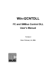
2.1 System architecture
The EEL driver is embedded in a strictly layered system and building up on NEC’s
self-programming library as a bridge between the flash control subsystem
(firmware and hardware) and the EEL. For details please refer to the flash selfprogramming library user’s manual.
Figure 2-1
EEPROM emulation layer model
Application Note U18991EE2V0AN00
11
Chapter 2
Architecture
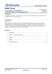
2.1.1 Import-, export-lists
The EEL driver is using the software interface (FSL API) offered by NEC’s flash
self-programming library (FSL). On its part the EEL driver offers a dedicated user
interface (EEL API) can be used by the application for operative and administrative
measures like command execution and operation supervision. The precompiled
EEL like the FSL, contains an user configurable parts bordered in red.
Figure 2-2
12
import export diagram (RAM variables marked in blue)
Application Note U18991EE2V0AN00
Architecture
Chapter 2
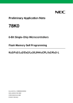
2.1.2 Module relationship
The file relationship of the EEL library obeys strict hierarchical top down order.
Figure 2-3
Note
include hierarchy diagram
1.
2.
3.
NEC compatible modules are marked in blue.
NEC compatible version of the EEL driver specifies the device file in
the project manager PM3+
IAR version of the EEL driver has to include the device I/O-file explicit
in eel_user.h
Application Note U18991EE2V0AN00
13
Chapter 2
Architecture
2.2 Driver architecture
The strongest requirement for the design of the driver was avoiding of blocking
time during driver operation time. For that reason this EEL implementation
dispenses of any automatic mode, like automatic copy process (refresh),
automatic erase process (prepare) and others. The application can check the
internal status of the driver and can initiate appropriate command at most
convenient time. This can be used to prepare erased blocks in advance in
uncritical timing situation. Leaned on a typical client-server architecture the
application (client) can formulate some requests (commands) and can “send” it
to the server via proprietary software interface. However in case of the 78k0 EEL
driver command queuing is not implemented, its architecture and the chosen
application interface are already prepared for that.
2.2.1 Request response model
The user application can use the pre-defined data type t_eel_request to define a
private EEL request variable. Using the request variable the application and the
EEL driver can exchange information. The owner task can formulate and “send”
private requests to the EEL driver. On the other hand the EEL driver can use it for
sending feedback to the “requester”. The request variable is synchronizing the
application and the driver. Please have a look to chapter 3.2 for details.
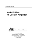
2.2.2 Resource consumption and its distribution
The EEL is consuming some resources distributed across the device memory
address space.
From compiler/linker point of view, the EEL driver consists of three logical parts:
•
•
•
user configurable source file where all driver parameter are defined
precompiled EEL library containing the whole driver functionality
self-programming library interfacing the firmware
Each of the above parts claims resources as shown in the figure below:
Figure 2-4
14
resource distribution
Application Note U18991EE2V0AN00
Architecture
Chapter 2
2.2.3 Physical placement of driver components
In the EEL driver the part where the data are stored is completely independent
from the part where the driver code is stored. The EEL driver code is fully relocatable and can be linked into the application code as a pre-compiled library.
The EEL pool area defined by the user is complete out of linker control. Please
take care, that EEL_POOL and application code does not overlap by creation of
a suitable linker description file (*.DR for NEC linker or *.XCL for the IAR compiler).
Figure 2-5
physical placement inside device flash memory
2.2.4 EEL anchor
The ROM constant eel_anchor[...] contains the description of all variables the
EEL driver can handle. It reserves unique identifier code for each EEL variable and
defines its size expressed in bytes and flash-words. Other identifier than defined
in eel_anchor[] cannot be used. Zero flash-word has to terminate the array
eel_anchor[...]
The eel_anchor[var_no+1][4] is a two dimensional array of bytes. Both
dimensions are defined automatically without user intervention. The only
configurable parameter influencing the dimension is the constant
EEL_VAR_NO. Each element of eel_anchor[N] is a complete EEL variable
descriptor consisting of 4 bytes:
Application Note U18991EE2V0AN00
15
Chapter 2
Architecture
Figure 2-6
eel_anchor[N][0]
EEL variable identifier (unique inside the eel_anchor).
Valid range 0x01…0xFE (253 identifiers possible).
eel_anchor[N][1]
EEL variable size expressed in flash word units.
Valid range 0x01…0x40 (1..64 words possible).
eel_anchor[N][2]
EEL variable size expressed in flash byte units (1…254)
Valid range 0x01…0xFF (1..255 bytes possible).
eel_anchor[N][3]
0x00, limiter
EEL anchor structure (example).
2.2.5 EEL pool
the EEL_pool is a flash area consists of 2-4 subsequent flash blocks where the
EEL instances are stored. The flash blocks of the EEL-pool are organized like a
ring where the “activated” status is passed to the next higher block by the refresh
command (for details refer to the command description). When the last block is
reached, the 1’st one becomes the “activated” one after “refresh”. To have at least
one redundant block in spare that can be excluded in case of flash problems the
recommended min. pool-size is 3 blocks. When no active block can be found by
StartUp command the complete EEL_POOL has to be formatted by using the
"format" command. All data are lost in that case.
Figure 2-7
16
EEL pool
Application Note U18991EE2V0AN00
Architecture
Chapter 2
2.2.6 EEL block
Each of the flash blocks belonging to the EEL_POOL is structured in the same
wise. On the top two flash words are used as block status flags followed by the
erase counter. Underlying the instance lookup table is used for stacking the
instance references from the top to the bottom. At the bottom of the active block
the referenced instances are stacked in the opposed direction. Both zones are
running contrary to meet somewhere in the middle of the block. At least one
"erased" flash word called separator has to isolate both zones. In case the
separator is not available in the active block, the complete EEL_POOL hast to be
formatted by using the "format" command. All data are lost in that case.
Figure 2-8
Typical structure of an EEL block
Application Note U18991EE2V0AN00
17
Chapter 2
Architecture
2.2.7 EEL reference table
The EEL reference table is a simple RAM vector defined in eel.c.
The number of EEL variables managed by the driver hast to be configured in the
header-file eel.h
eel_u08 eel_reference[EEL_VAR_NO];
The read-pointer of each EEL variables is saved there to accelerate read access
and makes the read access time independent of fill status of the active block.
Linear search of the youngest instances is not necessary anymore. The reference
table is initialized during startup command and updated in each write access. A
refresh command is modifying the reference table to. Analogical, the separator
word-index is used as a write pointer inside the active block to provide constant
write access time. The separator widx is not visible to the user.
The reference table is automatically defined in eel_user.c. The user does not need
to take care of the right dimension.
2.2.8 EEL instance lookup table
The Instance Lookup Table (ILT) is located at the begin of the active block and
realizes two main purposes:
•
•
Figure 2-9
Note
18
connection between the EEL variable identifier (identifier field) and
its written instance (widx field)
detection of problems caused by unexpected disturbance like
asynchronous power on RESET, power supply voltage drop or
others.
Instance lookup table (ILT) structure
Each write access is divided into two separated phases. In the first one the
reference is written into the ILT to allocate the needed space inside the data flash
Application Note U18991EE2V0AN00
Architecture
Chapter 2
area (DFA). In the second one the actual data of the written instance are written
into the DFA.
2.2.9 EEL data flash area
The Data Flash Area (DFA) is located at the end of the active block and contains
the pure data of the written instances only. The DFA is growing downstairs from
higher addresses to lower addresses inside the active block.
Figure 2-10
Note
Data flash area (DFA) structure
The content of unused bytes inside the instance data is undefined.
Application Note U18991EE2V0AN00
19
Chapter 3 Application Programming Interface
The application programmer interface is completely defined in the header file
eel.h It contains all necessary constant, type definitions as well all function
prototypes interfacing the functionality of the EEL driver. The interface definition
is fully C-compatible even though the implementation is done in assembler.
3.1 Constant definitions
All constants used for the EEL driver operation are available in form of
enumeration types defined in eel.h. The meaning of all particular enumeration
codes is described in the following chapter "Data type definitions".
3.2 Data type definitions
All data types used by the EEL driver are defined in the eel.h header file.
Table 3-1
20
overview of predefined data types
data type
description
eel_block_status_t
enumeration type for coding the status of each EEL pool block
eel_command_t
enumeration type for coding the available commands
eel_status_t
enumeration type for coding the driver and request status
eel_error_t
enumeration type coding all possible errors
eel_request_t
structure type for definition of EEL request variables
Application Note U18991EE2V0AN00
Application Programming Interface
Chapter 3
3.2.1 Block status type
Each block of the EEL_POOL contains two 32-bit status flags F0 and F1 on its
top. Both flags are coding all the block conditions can appear during EEPROM
emulation. The data type eel_block_status_t reflects all relevant combination of
both status flags.
Table 3-2
EEL block status code
block flag pattern
block status code
comment
F0=0xFFFFFFFF
F1=0xFFFFFFFF
EEL_BLK_ERASED
status of a virgin erased block,
means “block can be prepared”
F0=0xFFFFFFFF
F1=0x555555555
EEL_BLK_PREPARED
block status after "prepare" or
"format", means “block can be
activated”
F0=0x55555555
F1=0x55555555
EEL_BLK_ACTIVATED
status of EEL block being “in
use”, contains actual data
F0=0x55555555
F1=0x00000000
EEL_BLK_CONSUMED
block filled up with old instances,
means “block can be prepared”
F0=0x00000000
F1=0x00000000
EEL_BLK_EXCLUDED
after problems the block was
excluded by the application
other pattern than above
EEL_BLK_INVALID
blocks outside EEL pool
EEL_BLK_UNDEFINED
unknown status, means "block
has to be repaired"
the specified block does not
belong to the EEL pool area
Caution:
The block status reflects only the interpretation of both status flags F0 and F1.
Power-on RESET during execution time of the erase command can produce
scenarios where even though both flags are indicating the “erased” status, some
words inside are not erased correctly. The only one way to ensure, that the status
flags express the real physical status of the blocks is the positive termination of
the StartUp command.
Application Note U18991EE2V0AN00
21
Chapter 3
Application Programming Interface
3.2.2 Command code type
All commands provided by the EEL driver are represented by the enumeration
type eel_command_t.
Table 3-3
EEL command code
Command code
Comment
Electrical and logical plausibility checks of all blocks
belonging to the EEL pool
EEL_CMD_STARTUP
EEL_CMD_WRITE
Writes the actual data of an EEL-variable from its mirror
variable (RAM) into the active block of the EEL pool. Creates
a new instance of the EEL-variable.
EEL_CMD_READ
the data of the youngest instance of the specified EELvariable are copied into its mirror-variable (RAM)
EEL_CMD_REFRESH
Copies the lates instances of all registered EEL variables
into the next "fresh" block.
EEL_CMD_FORMAT
Create a virgin EEL-pool, all instances of EEL-variables are
lost
EEL_CMD_PREPARE
the next “non-prepared” and “non-active” block is erased
and marked as “prepared”
EEL_CMD_REPAIR
Erase and mark as “prepared” the specified block
EEL_CMD_EXCLUDE
Excludes the specified block from pool EEL management.
EEL_CMD_SHUTDOWN
Verifies the active block to ensure the data retention of the
data inside. Disables read- and write-access.
3.2.3 Status type
The predefined type eel_status_t ca be used for two different purposes. The first
one is to indicate the status of the EEL request serviced by the driver. The other
one meaning is to represent the internal status of the EEL driver themselves.
Table 3-4
request and driver status codes
status code
EEL_STS_READY
EEL_STS_ACTIVE
EEL_STS_ABORTED
related to Comment
request
the related request was finished successfully
driver
the driver is ready to accept any EEL request
request
driver
request
driver
driver is processing a request in background mode
the driver is processing any request
the request is not finished due to any problems
not relevant
Use cases:
1.
2.
3.
The request-status can be used by the application (the requesting
task) for checking the status of its own request (polling mode).
The EEL driver-status can be used by the application to check the
availability of the EEL driver in advance.
Before entering the standby mode the application can check whether
any EEL request is pending and can wait active until it’s finished.
Note: The function EEL_CheckDriverStatus() can be used for 2) and 3).
22
Application Note U18991EE2V0AN00
Application Programming Interface
Chapter 3
3.2.4 Error type
All error codes supported by the driver during execution of EEL requests are
collected in the predefined enumeration type eel_error_t. In case of problems the
application can analyze the error-code to identify the reason.
Table 3-5
EEL error code
Error code
meaning
EEL_OK
no error occurred during command execution
EEL_ERR_PARAMETER
1)
parameter error (FSL)2)
EEL_ERR_PROTECTION
protection error (FSL)2)
EEL_ERR_ERASE
flash block could not been erased (FSL)2)
EEL_ERR_VERIFY
data couldn't be verified (FSL)2)
EEL_ERR_WRITE
data could not been written into flash (FSL)2)
EEL_ERR_EEPWRITE_VERIFY
verify error during writing into flash (FSL)2)
EEL_ERR_EEPWRITE_BLANK
area not blank, data remain untouched (FSL)2)
EEL_ERR_INTERRUPTED
self-programming interrupted (FSL)2)
EEL_ERR_DRIVER_BUSY
the driver is currently busy with an other request
EEL_ERR_STARTUP_MISSING
read/write access is disabled as long "startup"
isn’t executed successfully
EEL_ERR_POOL_CONSUMED
no “prepared” block available for “refresh”
execution
EEL_ERR_BLOCK_CONSUMED
no space for the instance in the active block
EEL_ERR_FLMD0_LOW
FLMD0 signal error
EEL_ERR_TWO_ACTIVE_BLOCKS
startup found two EEL blocks marked as “active”
EEL_ERR_BLOCK_NOT_EMPTY
any “prepared” block contains undefined data.
EEL_ERR_BLOCK_INVALIDE
EEL block status flags couldn’t been interpreted
EEL_ERR_INSTANCE_UNKNOWN
specified EEL variable was never written
EEL_ERR_VARIABLE_CHECKSUM
checksum of the read instance does not match
EEL_ERR_NO_ACTIVE_BLOCK
startup could not recognize any “active” block
EEL_ERR_SEPARATOR_LOST
ILT and DFA not separated anymore
EEL_ERR_POOL_EXHAUSTED
less than two "healthy" blocks inside the EEL-pool
EEL_ERR_COMMAND_UNKNOWN invalid command code detected
EEL_ERR_POOL_SIZE
invalid EEL pool configuration
EEL_ERR_VARIABLE_UNKNOWN
variable identifier not registered in eel_anchor[]
EEL_ERR_PROTECTED_BLOCK
block protected against "repair" or "exclude"
Note 1)
this error can happen when any of the EEL RAM mirror variables is located in the
short-address area 0xFE20…0xFE83. The reason is, that this RAM area cannot
be used by the firmware as a data-buffer. To reduce the RAM consumption and
CPU time the EEL driver is using the EEL RAM mirror variables directly as databuffer. Other user variables can be located in area 0xFE20…0xFE83 without
restrictions.
Application Note U18991EE2V0AN00
23
Chapter 3
Application Programming Interface
Note 2)
Error generated by the Flash Selfprogramming Library converted (FSL error code
+ 0x80) and passed directly to EEL.
3.2.5 Request type
Using the predefined request type the application can create request variables
and use it for communication and synchronization purpose with the EEL driver.
Status of the request can be polled and error code can be analyzed in case of any
problems. It's practically the central point of interaction between the application
and the EEL driver. The request data type is predefined in eel.h
// EEL request type (base type for any EEL access)
typedef struct
{
eel_u08*
address;
// 2, source/destination address
eel_u08
identifier; // 1, identifier (variable/block)
eel_command_t
command;
// 1, command has to be processed
eel_status_t
status;
// 1, status during/after execution
eel_error_t
error;
// 1, error after command execution
} eel_request_t;
// -------------------------------// 6 bytes in total
Figure 3-1
request variable synchronizing EEL and the application
Variables of that type can be used as a kind of common area where the application
and the EEL driver can exchange information. The application formulates the
request (command) and initiates the execution. The driver is returning the requeststatus and error-code. The parameter-less commands like "startup" or
"prepare" can return the related block number in identifier-field when problems
occur.
24
Application Note U18991EE2V0AN00
Application Programming Interface
Chapter 3
3.3 Function prototypes
The functions offered by the EEL API are divided in operative and administrative.
Operative functions are responsible for the pure request registration and request
execution. Administrative functions can be used by the application to examine
the status of some internal EEL parameters. Based on that information the
application can always act and react in suitable and reasonable wise depending
on its own context.
Table 3-6
EEL function overview
functions
operative
administrative
description
EEL_Init()
driver initialization
EEL_Enforce(…)
request and execution in standalone
applications
EEL_Execute(…)
request in real-time applications
EEL_Handler()
execution in real-time applications
EEL_CheckDriverStatus()
returns the current EEL driver status
EEL_GetPool()
returns the number of “prepared”
blocks
EEL_GetSpace()
returns the number of free words
inside the active block
EEL_GetBlockStatus(...)
returns the status of the specified
block
EEL_GetActiveBlock()
returns the number of the "active"
block
EEL_GetNextBlock()
returns the number of the
subsequent, "non-excluded" block
to the "active" one
EEL_GetPrevBlock()
returns the number of the previous,
"non-excluded" block to the "active"
one
3.3.1 EEL_Init()
This parameter less function should be used during power-on initialization of the
device. All internal EEL variables are initialized but the driver remains inactive.
3.3.2 EEL_Enforce(my_request)
This function can be used to execute any EEL command in so called “enforced"
mode. This way of command execution is designed to support standalone
applications. Such an application can call EEL_Enforce() to execute specified
command and waits at the calling position until the command execution is
completed. From the application point of view it works like a simple call, but it
takes much “longer” time. During the command execution in “enforced" mode all
enabled interrupts will be serviced with a delay specific for the self-programming
commands used inside the EEL command.
Application Note U18991EE2V0AN00
25
Chapter 3
Application Programming Interface
Figure 3-2
Typical flow of an interrupted EEL command in “enforced" mode
Code example:
// “StartUp” commad request
my_eel_request.command = EEL_CMD_STARTUP;
EEL_Enforce(&my_eel_request);
if (my_eel_request.status == EEL_STS_ABORTED)
my_EEL_ErrorHandler();
3.3.3 EEL_Execute(my_request)
This function can be used to execute any EEL command in so called
“background" mode. This way of command execution is designed to support realtime multitasking applications. Such applications reserve a time slice for the EEL
task (process) and calls periodically EEL_Execute() to execute specified
command in predetermined time pieces until the command execution is
completed. The application can check the status of its own EEL request by polling
the variable my_request.status. In between the time slices the application
reclaims the fully control about the CPU and can manage time critical tasks, like
watchdog reset or readout and release of communication-buffer. During the
command execution in “background mode” all enabled interrupts will be serviced
with a delay specific for the self-programming commands used inside the EEL
command.
26
Application Note U18991EE2V0AN00
Application Programming Interface
Figure 3-3
Chapter 3
Typical flow of EEL command execution in “background mode”
Code example:
“StartUp” commad request
my_eel_request.command = EEL_CMD_STARTUP;
EEL_Execute(&my_eel_request);
my_state = default_state;
if (my_eel_request.status == EEL_STS_ABORTED)
if (my_eel_request.status == EEL_STS_ACTIVE)
my_state = error_state;
my_state = polling_state;
3.3.4 EEL_Handler()
This function can be used to execute EEL command time-slice by time-slice in so
called “background " mode. Typically, it should be called in the scheduler loop to
share the CPU time with other processes. Theoretically the EEL_Handler() can
also be called in a waiting-loop, but better to use EEL_Enforce() directly for such
purpose. Have a look to the listing below that illustrates the typical use-case for
the EEL handler.
Application Note U18991EE2V0AN00
27
Chapter 3
Application Programming Interface
Code examples:
1)
//
//
//
do
----------------------------------------------OS scheduler's idle loop (cooperative system)
----------------------------------------------{
EEL_Handler();
if (task_A.tcb.status==active) (*task_A.tcb.state)();
if (task_B.tcb.status==active) (*task_B.tcb.state)();
if (task_C.tcb.status==active) (*task_C.tcb.state)();
if (task_D.tcb.status==active) (*task_D.tcb.state)();
} while (true);
2)
// --------------------------// possible, but not preferable
// --------------------------my_eel_request.command = EEL_CMD_STARTUP;
EEL_Execute(&my_eel_request);
while (my_eel_request.status) == EEL_STS_ACTIVE
{
EEL_Handler();
}
if (my_eel_request.status == EEL_STS_ABORTED) my_EEL_ErrorHandler();
3.3.5 EEL_CheckDriverStatus()
This function can be used to check the internal status of the EEL driver in advance
before placing the EEL request. Also other administrative functions requiring
"ready" status can use EEL_CheckDriverStatus() to check it.
The result returned by EEL_CheckDriverStatus() is:
•
•
Note
EEL_STS_READY – when he EEL driver is ready to accept a new
request.
EEL_STS_ACTIVE – when the EEL driver is processing an other
request in “background mode”
The status returned by this function cannot be “EEL_STS_ABORTED”. This value
is reserved for request status only.
Code examples:
1) check in advance if request acceptable
// --------------------------------------if (EEL_CheckDriverStatus()==EEL_STS_READY)
{
my_eel_request.command = EEL_CMD_PREPARE;
EEL_Execute(&my_eel_request);
if (my_eel_request.status == EEL_STS_ABORTED)
};
my_EEL_ErrorHandler();
2) check if driver "passive" before reading its parameter
// ------------------------------------------------------if (EEL_CheckDriverStatus()==EEL_STS_READY)
my_eel_space = EEL_GetSpace();
28
Application Note U18991EE2V0AN00
Application Programming Interface
Chapter 3
3.3.6 EEL_GetPool()
This function provides the number of “prepared” coherent blocks inside the EEL
pool. The application can use it to check the stock of prepared blocks in advance
at most convenient time.
Code example:
if (EEL_CheckDriverStatus()==EEL_STS_READY) my_eel_pool = EEL_GetPool();
3.3.7 EEL_GetSpace()
This function provides the “free” space inside the active block. The application
can use it to check if the available space is sufficient for the incoming write access,
but it has to take care, that the driver is not “busy” at that time. The returned value
represents the erased space inside the active block expressed in flash words (4
bytes)
Code example:
if (EEL_CheckDriverStatus()==EEL_STS_READY)
my_eel_space = EEL_GetSpace();
3.3.8 EEL_GetBlockStatus(my_block_u08)
This function provides the status of the specified EEL block. It can be useful for
reparation purpose when the application has to distinguish between active and
other block.
Code example:
if (EEL_CheckDriverStatus()==EEL_STS_READY)
{
if (EEL_GetBlockStatus()==EEL_BLK_ACTIVATED)
my_request.command = EEL_CMD_REFRESH;
else
my_request.command = EEL_CMD_PREPARE;
}
EEL_Enforce(&my_eel_request);
if (my_eel_request.status == EEL_STS_ABORTED)
Application Note U18991EE2V0AN00
my_EEL_ErrorHandler();
29
Chapter 3
Application Programming Interface
3.3.9 EEL_GetActiveBlock()
This function provides the number of currently "active" block. It can be useful for
reparation purpose.
Code example:
if (EEL_CheckDriverStatus()==EEL_STS_READY)
my_active_block = EEL_GetActiveBlock();
3.3.10 EEL_GetNextBlock()
This function provides the number of next block to the currently "active" one.
Blocks marked as "excluded" are ignored. It can be useful for reparation purpose.
Code example:
if (EEL_CheckDriverStatus()==EEL_STS_READY)
my_active_block = EEL_GetNextBlock();
3.3.11 EEL_GetPrevBlock()
This function provides the number of previous block to the currently "active" one.
Blocks marked as "excluded" are ignored. It can be useful for reparation purpose.
Code example:
if (EEL_CheckDriverStatus()==EEL_STS_READY)
my_active_block = EEL_GetPrevBlock();
30
Application Note U18991EE2V0AN00
Chapter 4 Commands
The available command codes are defined in the enumeration type
eel_command_t. The EEL commands can be divided into two groups: operative
(necessary for access to the virtual EEPROM) and administrative (used for
administrative measures necessary for smooth and secure driver operation).
Table 4-1
EEL command overview
commands
operative
administrative
EEL_CMD_STARTUP
short description
plausibility check of the EEL, unlocks access to EEL
EEL_CMD_WRITE
write access to virtual EEPROM memory
EEL_CMD_READ
read access to virtual EEPROM memory
EEL_CMD_PREPARE
formats of one additional (subsequent) block
EEL_CMD_REFRESH
copy all recent instances into a fresh block
EEL_CMD_REPAIR
formats of one dedicated block
EEL_CMD_FORMAT
formats the complete EEL pool (all blocks), data are
lost
EEL_CMD_EXCLUDE
excludes one block from EEL pool management
EEL_CMD_SHUTDOWN
electrical check of the active EEL block, locks the
access to EEL
Application Note U18991EE2V0AN00
31
Chapter 4
Commands
4.1 startup
The StartUp command is checking the plausibility and consistency of the EEL
pool. This is the first command has to be executed before read- and write-access
to the EEL is possible at all. Before the structure of each block can be analyzed
logically, the electrical status of the information stored in the flash is checked by
the self-programming command “verify”. After that the status of each block and
its logical block structure can be analyzed. Finally the reference table (all EEL
variable read pointer) and the separator-index (EEL write pointer) are initialized to
achieve fast and constant read/write access time.
State sequence of the startup command:
1.
2.
3.
4.
plausibility check of EEL configuration data (descriptors in
eel_user.c)
electrical verification of each block of the EEL pool
structure and status of the EEL pool
status and structure of each block
Self-programming commands used by startup
•
32
FSL_IVerify(my_block_u08)
Application Note U18991EE2V0AN00
Commands
Chapter 4
Startup request and feedback
To initiate the startup command the application has to specify the command code
only. Any problems during startup execution time will be signaled in the request
variable via its status and error members. In case of block related problems, the
number of the affected block can be found in the identifier field. The application
(its central error handler) has to take care for reparation. After that the startup
command has to be executed again.
Code example:
// “StartUp” commad request
my_eel_request.command = EEL_CMD_STARTUP;
EEL_Enforce(&my_eel_request);
if (my_eel_request.status == EEL_STS_ABORTED)
my_EEL_ErrorHandler();
Startup error handling
Whenever problems are detected during “startup”-command execution, the
request status is modified by the EEL driver to “EEL_STS_ABORTED”. In such a
case the application has to analyze the error code and initiate appropriate
reparation. The possible error codes with corresponding reparation rules can be
found below:
Application Note U18991EE2V0AN00
33
Chapter 4
Commands
Table 4-2
Startup error code
startup error codes
EEL_ERR_DRIVER_BUSY
class
normal
error background and handling
meaning
driver is already “busy” with another
request
reason
another task already initiated its own
request
remedy
wait until driver-status is “ready” and
retry
meaning undefined command code detected
EEL_ERR_COMMAND_UNKNOWN
EEL_ERR_BLOCK_INVALIDE
EEL_ERR_BLOCK_NOT_EMPTY
EEL_ERR_VERIFY
reason
propably wrong command code used
by the user
remedy
check source code, correct the
command code and re-compile the
project.
meaning
block status flags F0/F1 could not be
interpreted
reason
probably RESET during writing F0/F1
remedy
execute “repair” command and
“startup” again.
meaning
A “prepared” block is not “erased”
anymore.
reason
probably RESET during “refresh”
command
remedy
execute “repair” command and
“startup” again.
meaning
the level of some data dropped below
the verify level
reason
RESET during writing into flash, data
retention
initial
middle
middle
middle
remedy
EEL_ERR_TWO_ACTIVE_BLOCKS
middle
1) affected block is the “active”–>
execute “refresh”
2) affected block is not “active” ->
execute “repair”
meaning
there are two “active” blocks detected
in the EEL pool
reason
RESET during execution of “refresh”
command
remedy
execute “repair” command and
“startup” again.
meaning ILT and DFA not separated anymore
EEL_ERR_SEPARATOR_LOST
EEL_ERR_NO_ACTIVE_BLOCK
EEL_ERR_POOL_EXHAUSTED
34
heavy
heavy
fatal
reason
EMI, malfunction, flash problems
remedy
execute “format” , all data are lost
meaning
no “active” block detected during
startup
reason
possibly EMI, malfunction, flash
problems
remedy
execute “format”, all data are lost
meaning
EEL pool consists of less than two
“healthy” blocks
reason
flash endurance exceeded
remedy
none
Application Note U18991EE2V0AN00
Commands
Chapter 4
Application Note U18991EE2V0AN00
35
Chapter 4
Commands
4.2 write
The write command is writing a data-set of a registered EEL variable from its RAMmirror into the virtual EEPROM memory. The application has to specify the
identifier and the starting address of the RAM-mirror variable before initiating the
command execution.
Caution:
The EEL RAM mirror variables shouldn't be located in the short-address area
0xFE20…0xFE83 because this area cannot be used by the firmware as a databuffer. To reduce the RAM consumption of the driver the EEL RAM variables are
used directly as a kind of "temporary data-buffer" during the write command.
Other user variables can be located in area 0xFE20…0xFE83.
State sequence of the write command:
1.
2.
3.
allocating the space for the data by writing the new reference into
the ILT
writing the new data set into the allocated space inside the DFA
actualize the corresponding EEL variable reference inside the
eel_reference[…]
Self-programming commands used by write command
•
36
FSL_EEPROMWrite(my_addr_u32, my_wordcount_u08)
Application Note U18991EE2V0AN00
Commands
Chapter 4
Write request and feedback
The application has to specify the EEL variable identifier of and the starting
address of the RAM-mirror variable.
Code example:
// “Write” commad request
my_eel_request.command
= EEL_CMD_WRITE;
my_eel_request.identifer = ‘A’;
my_eel_request.address
= (eel_u08*)&A[0];
EEL_Enforce(&my_eel_request);
if (my_eel_request.status == EEL_STS_ABORTED)
my_EEL_ErrorHandler();
Write error handling
Whenever problems are detected during “write”-command execution, the request
status is modified by the EEL driver to EEL_STS_ABORTED. In such a case the
application can analyze the error code and react to properly to that exception.
The possible error codes with recommended reparation rules can be found below:
Application Note U18991EE2V0AN00
37
Chapter 4
Commands
Table 4-3
Write command error handling
write error codes
class
error background and handling
meaning driver is already “busy” with a request
EEL_ERR_DRIVER_BUSY
normal
reason
another task initiated its own request
remedy
wait until driver-status is “ready” and
retry
meaning write access is not yet enabled
EEL_ERR_STARTUP_MISSING
normal
reason
“startup” command wasn’t successful
till now
remedy
execute “startup” and “write” again
meaning the active block is full
EEL_ERR_BLOCK_CONSUMED
EEL_ERR_VARIABLE_UNKNOWN
normal
initial
reason
size of the EEL variable exceeds the
available space
remedy
execute the “refresh” command and
“write” again
meaning
specified EEL variable unknown by the
EEL driver
reason
used identifier is not registered in
eel_anchor[]
remedy
register variable in eel_anchor[], recompile the project
meaning FLMD0 signal error
EEL_ERR_FLMD0_LOW
EEL_ERR_EEPWRITE_BLANK
EEL_ERR_EEPWRITE_VERIFY
EEL_ERR_WRITE
unlikely
heavy
reason
FLMD0 signal remains LOW during
self-programming
remedy
check FLMD0 hardware and software
meaning
the destination flash area in not erased
enymore
reason
possibly EMI, malfunction, flash
problems
remedy
execute the “refresh” command and
“write” again
meaning
the written data could not be verified
electrically
reason
power, EMI or flash problem
remedy
retry write up to 3 times, if not
successful:
execute “refresh” and “exclude” the
previous block and "write" again
meaning
the data could not be written correctly
into flash
reason
power, EMI or flash problem
remedy
retry write up to 3 times, if not
successful: execute “refresh” and
“exclude” the previous block and
"write" again
heavy
heavy
meaning no “active” block found
EEL_ERR_NO_ACTIVE_BLOCK
38
heavy
reason
possibly EMI, malfunction
remedy
execute “format” command, all data
are lost
Application Note U18991EE2V0AN00
Commands
Chapter 4
4.3 read
The read command can be used to read the youngest written data-set from the
virtual EEPROM memory into the specified RAM-mirror variable. Beside the
command-code, the application has to specify the identifier of the EEL-variable
and the starting address of the RAM-mirror variable.
State sequence of the read command:
The read command returns immediately the result of the read-access,
independent whether “background” or “enforced” mode was used for the
execution. The actual data-set is copied immediately from flash into the RAM
mirror variable.
1.
2.
3.
4.
search active block
search the actual instance
check the checksum
copy data of the instance into RAM mirror variable
Self-programming commands used by read command
•
none FSL function is used
Read request and feedback
The application has to specify the EEL variable identifier and the starting address
of the RAM-mirror variable.
Application Note U18991EE2V0AN00
39
Chapter 4
Commands
Code example:
// “Read” commad request
my_eel_request.command
= EEL_CMD_READ;
my_eel_request.identifer = ‘A’;
my_eel_request.address
= (eel_u08*)&A[0];
EEL_Enforce(&my_eel_request);
if (my_eel_request.status == EEL_STS_ABORTED)
my_EEL_ErrorHandler();
Read error handling
Whenever problems are detected during “read”-command execution, the request
status is modified by the EEL driver to EEL_STS_ABORTED. In such a case the
application can analyze the error code and react properly to that exception. The
possible error codes with corresponding reparation rules can be found below:
Table 4-4
Read error handling
read error code
EEL_ERR_DRIVER_BUSY
class
normal
error background and handling
meaning
driver is already “busy” with another
request
reason
another task initiated its own request
remedy
wait until driver-status is “ready” and
retry
meaning read access is not yet enabled
EEL_ERR_STARTUP_MISSING
EEL_ERR_VARIABLE_UNKNOWN
EEL_ERR_INSTANCE_UNKNOWN
normal
initial
normal
reason
“startup” command wasn’t successful
till now
remedy
execute “startup” and “read” again
meaning
specified EEL variable unknown by the
EEL driver
reason
used identifier is not registered in
eel_anchor[]
remedy
register variables in eel_anchor[], recompile the project
meaning
no data set found for the used EEL
variable
reason
the used EEL variable was never
written into EEL
remedy
initialize the EEL variable by writing
initial value
meaning checksum error detected
EEL_ERR_VARIABLE_CHECKSUM
EEL_ERR_NO_ACTIVE_BLOCK
40
normal
heavy
reason
RESET during last EEL write access
remedy
over-"write” the EEL variable with
corrected value
meaning
no “active” block detected during
startup
reason
possibly EMI, malfunction
remedy
execute “format” command, all data
are lost
Application Note U18991EE2V0AN00
Commands
Chapter 4
4.4 refresh
Each write access to the virtual EEPROM consumes some “erased” space within
the active block as long as enough space is available. When the active block
becomes full, the write access is not possible anymore. To enable the write access
new space has to be created. The refresh command is doing that by copying the
relevant information only from the currently "active" (full) block into a
"prepared" (empty) one.
Especially when fast, immediately write access is required by the application, it
has to take care for enough space inside the active block in advance. This can be
performed by the application using the EEL_GetSpace() function and refresh
command. Depending on the situation the application can realized it immediately
or at more comfortable time in advance.
State sequence of the refresh command:
The refresh command is performed in three steps:
1.
2.
3.
copy all latest instances of all registered EEL variables into the
subsequent block.
mark the new, “fresh” block is marked as “active”
mark the old one block as “consumed”.
However asynchronous RESET during execution of the refresh command can
produced some inconsistencies that has to be detected by the startup command
and has to be repaired by the application.
Application Note U18991EE2V0AN00
41
Chapter 4
Commands
Self-programming commands used by refresh command
•
•
FSL_EEPROMWrite(my_addr_u32, my_wordcount_u08)
FSL_Write(my_addr_u32, my_wordcount_u08)
Refresh request and feedback
The application has to specify the command code only.
Code example:
// “Refresh” commad request
my_eel_request.command
= EEL_CMD_REFRESH;
EEL_Enforce(&my_eel_request);
if (my_eel_request.status == EEL_STS_ABORTED)
my_EEL_ErrorHandler();
Refresh error handling
Whenever problems are detected during “refresh”-command execution, the
request status is modified by the EEL driver to EEL_STS_ABORTED. In such a
case the application can analyze the error code and react properly to that
exception. The possible error codes with corresponding reparation rules can be
found below:
42
Application Note U18991EE2V0AN00
Commands
Chapter 4
Table 4-5
Refresh error handling
refresh error codes
EEL_ERR_DRIVER_BUSY
class
normal
error background and handling
meaning
driver is already “busy” with another
request
reason
another task initiated its own request
remedy
wait until driver “ready” and retry
meaning no “prepared” block for "refresh"
EEL_ERR_POOL_CONSUMED
normal
reason
all clocks were consumed or are
invalide
remedy
execute “prepare” and “refresh”
again
meaning FLMD0 signal out of control
EEL_ERR_FLMD0_LOW
unlikely
reason
FLMD0 signal remains LOW during
self-programming
remedy
check FLMD0 hardware/software
meaning EEL variables unknown by the EEL
EEL_ERR_VARIABLE_UNKNOWN
EEL_ERR_BLOCK_CONSUMED
EEL_ERR_EEPWRITE_BLANK
EEL_ERR_EEPWRITE_VERIFY
EEL_ERR_WRITE
initial
unlikely
heavy
heavy
heavy
reason
used identifier is not registered in
eel_anchor[]
remedy
register variable in eel_anchor[], recompile the project
meaning
no space for initial data inside the
“new” block
reason
the sum of EEL variable sizes
remedy
reduce the amount of data (count or
size of variables) and re-compile the
project.
meaning
the destination flash area is not erased
anymore
reason
possibly EMI, malfunction, flash
problems
remedy
"repair" next block and "refresh"
again
meaning
the written data could not be verified
electrically
reason
possibly EMI, malfunction, flash
problems
remedy
“exclude” next block, execute
"prepare" and "refresh" again
meaning
the data could not be written correctly
into flash
reason
possibly EMI, malfunction, flash
problems
remedy
“exclude” next block, execute
"prepare" and "refresh" again
meaning no “active” block found
EEL_ERR_NO_ACTIVE_BLOCK
heavy
reason
possibly EMI, malfunction, flash
problems
remedy
execute “format” command, all data
are lost
Application Note U18991EE2V0AN00
43
Chapter 4
Commands
4.5 format
The format command is a command that should be used in exceptional cases
only. It erases the whole EEL pool, marks one block as “activated” and all other
blocks as “prepared”. All data in the previously “active” block are lost. The
application has to take care for re-incarnation (initial write) of all EEL variable after
“format”.
State sequence of the format command:
The format command erases the complete EEL pool block by block and writes
the header data into each of it. The block next to the previously active one
becomes "activated" after format. All other blocks becomes "prepared". The
erase counter is managed by the format command.
Self-programming commands used by format command
•
•
•
FSL_Erase(my_block_u08)
FSL_EEPROMWrite(my_addr_u32, my_wordcount_u08)
FSL_IVerify(my_block_u08)
Format request and feedback
The application has to specify the command code only. When problems occur
during execution the affected block number is provided by the driver in the
identifier field of the request variable.
44
Application Note U18991EE2V0AN00
Commands
Chapter 4
Code example:
// “Format” commad request
my_eel_request.command
= EEL_CMD_FORMAT;
EEL_Enforce(&my_eel_request);
if (my_eel_request.status == EEL_STS_ABORTED) my_EEL_ErrorHandler();
Format error handling
Whenever problems are detected during “format”-command execution, the
request status is modified by the EEL driver to EEL_STS_ABORTED. In such a
case the application can analyze the error code and react properly to that
exception. The possible error codes with corresponding reparation rules can be
found below:
Table 4-6
Format error handling
format error code
EEL_ERR_DRIVER_BUSY
class
light
error background and handling
meaning
driver is already “busy” with another
request
reason
another task initiated its own request
remedy
wait until driver-status is “ready” and
retry
meaning FLMD0 signal out of control
EEL_ERR_FLMD0_LOW
EEL_ERR_PROTECTION
EEL_ERR_EEPWRITE_BLANK
EEL_ERR_EEPWRITE_VERIFY
EEL_ERR_WRITE
EEL_ERR_ERASE
heavy
initial
unlikely
heavy
heavy
heavy
reason
FLMD0 signal remains LOW during
self-programming
remedy
check FLMD0 hardware and software
meaning
EEL driver tries to overwrite protected
area
reason
possibly EMI, malfunction, bootcluster
remedy
check EEL pool range
meaning
destination flash area is not blank
enymore
reason
possibly EMI, malfunction, flash
problems
remedy
depends on the origin of the problem
meaning
the written data could not be verified
electrically
reason
possibly flash problem
remedy
"exclude" the block and "format"
again
meaning
the data could not be written correctly
into flash
reason
possibly flash problem
remedy
"exclude" the block and "format"
again
meaning
the specified flash block could not be
erased
reason
possibly flash problems
remedy
"exclude" the block and "format"
again
Application Note U18991EE2V0AN00
45
Chapter 4
Commands
4.6 prepare
The prepare command looks for the next “consumed” or "erased" block inside
the EEL pool, erases and marks it as “prepared”. The application can execute this
command whenever it can take the liberty to spend time for that. In case that all
blocks of the EEL pool are already “prepared” the command will terminate
immediately with minimum of CPU load. It can be used by the application in
advance, just to avoid driver blocking at uncomfortable time period. Blocks
marked as “excluded” or “invalid” are over-jumped by the “prepare” command.
Especially when immediately write access is required by the application, it has to
take care for availability of at least one “prepared” block for execution of
unexpected “refresh” command. The administrative function EEL_GetPool() can
be used for that purpose
State sequence of the prepare command:
The prepare command is performed in two steps: 1) searching and erasing of the
next “consumed” or "erased" block. 2) marking of the erased block as “prepared”.
However asynchronous RESET during execution of the refresh command can
produced some inconsistencies that has to be detected by the startup command
and has to be repaired by the application.
Self-programming commands used by prepare command
•
•
FSL_Erase(my_block_u08)
FSL_EEPROMWrite(my_addr_u32, my_wordcount_u08)
Prepare request and feedback
The application has to specify the command code only. When problems occur
during execution the affected block number is provided by the driver in the
identifier field of the request variable.
46
Application Note U18991EE2V0AN00
Commands
Chapter 4
Code example:
// “Prepare” commad request
my_eel_request.command
= EEL_CMD_PREPARE;
EEL_Enforce(&my_eel_request);
if (my_eel_request.status == EEL_STS_ABORTED)
my_EEL_ErrorHandler();
Prepare error handling
Whenever problems are detected during execution of the “prepare”-command,
the request status is modified by the EEL driver to EEL_STS_ABORTED. In such
a case the application can analyze the error code and react properly to that
exception. The possible error codes with corresponding reparation rules can be
found below:
Application Note U18991EE2V0AN00
47
Chapter 4
Commands
Table 4-7
Prepare error handling
prepare error code
class
error background and handling
meaning driver is already “busy” with another request
EEL_ERR_DRIVER_BUSY
normal
reason
another task initiated its own request
remedy
wait until driver-status is “ready” and retry
meaning FLMD0 signal error
EEL_ERR_FLMD0_LOW
heavy
reason
FLMD0 signal remains LOW during selfprogramming
remedy
check FLMD0 hardware and software
meaning EEL driver tries to overwrite protected area
EEL_ERR_PROTECTED_BLOCK
EEL_ERR_EEPWRITE_BLANK
EEL_ERR_EEPWRITE_VERIFY
EEL_ERR_WRITE
heavy
unlikely
heavy
heavy
reason
the block is “active” or it doesn't belong to
EEL pool
remedy
check EEL pool range
meaning
the destination flash area ins not erased
enymore
reason
possibly EMI, malfunction, flash problem
remedy
depends on the origin of the problem
meaning
the written data could not be verified
electrically
reason
EMI, malfunction, flash problem
remedy
“exclude” the block, "prepare" again
meaning
the data could not be written correctly into
flash
reason
possibly flash problem
remedy
“exclude” the block, "prepare" again
meaning the specified flash block could not be erased
EEL_ERR_ERASE
heavy
reason
possibly flash problems
remedy
“exclude” the block, "prepare" again
meaning no “active” block detected during startup
EEL_ERR_NO_ACTIVE_BLOCK
heavy
reason
possibly EMI, malfunction, flash problems
remedy
execute “format” command, all data are lost
4.7 repair
The repair command erases and marks as “prepared” a specific block. This
command can be used for reparation purpose of undefined or inconsistent blocks.
State sequence of the repaire command:
The repair command is performed in two steps: 1) erasing of the specified block.
2) marking of the erased block as “prepared”. However asynchronous RESET
during execution of the refresh command can produced some inconsistencies
that has to be detected by the startup command and has to be repaired by the
application.
48
Application Note U18991EE2V0AN00
Commands
Chapter 4
Self-programming commands used by repair command
•
•
FSL_Erase(my_block_u08)
FSL_EEPROMWrite(my_addr_u32, my_wordcount_u08)
Repair request and feedback
The application has to specify the command code and the block number has to
be repaired.
Code example:
// “Repair” commad request
my_eel_request.command
= EEL_CMD_REPAIR;
my_eel_request.identifier= my_eel_block_u08;
EEL_Enforce(&my_eel_request);
if (my_eel_request.status == EEL_STS_ABORTED)
Application Note U18991EE2V0AN00
my_EEL_ErrorHandler();
49
Chapter 4
Commands
Repair error handling
Whenever problems are detected during execution of the “repair”-command, the
request status is modified by the EEL driver to EEL_STS_ABORTED. In such a
case the application can analyze the error code and react properly to that
exception. The possible error codes with corresponding reparation rules can be
found below:
Table 4-8
Repair error handling
repair error code
EEL_ERR_DRIVER_BUSY
class
normal
error background and handling
meaning
driver is already “busy” with another
request
reason
another task initiated its own request
remedy
wait until driver-status is “ready” and
retry
meaning FLMD0 signal out of control
EEL_ERR_FLMD0_LOW
heavy
reason
FLMD0 signal remains LOW during
self-programming
remedy
check FLMD0 hardware and software
meaning EEL driver tries to erase protected area
EEL_ERR_PROTECTED_BLOCK
EEL_ERR_EEPWRITE_BLANK
EEL_ERR_EEPWRITE_VERIFY
EEL_ERR_WRITE
EEL_ERR_ERASE
EEL_ERR_NO_ACTIVE_BLOCK
50
initial
unlikely
heavy
heavy
heavy
heavy
reason
the block is “active” or it doesn't
belong to EEL pool
remedy
correct the flow and re-compile the
project
meaning
the destination flash area is not erased
enymore
reason
possibly EMI, malfunction, flash
problems
remedy
depends on the origin of the problem
meaning
the written data could not be verified
electrically
reason
possibly flash problem
remedy
“exclude” the block
meaning
the data could not be written correctly
into flash
reason
possible flash problem
remedy
“exclude” the block
meaning
the specified flash block could not be
erased
reason
possible flash problem
remedy
“exclude” the block
meaning
no “active” block detected during
startup
reason
possibly EMI, malfunction, flash
problems
remedy
execute “format” command, all data
are lost
Application Note U18991EE2V0AN00
Commands
Chapter 4
4.8 exclude
The exclude command marks the specified block as “excluded”. It can be used
for exclude any EEL block, except the active one, from the EEL block
management. Data are not stored in that block anymore.
State sequence of the exclude command:
The exclude command overwrites both status flags of the specified EEL block
with the pattern 0x00000000. However asynchronous RESET during execution of
the refresh command can produced some inconsistencies that has to be detected
by the startup command and has to be repaired by the application.
Self-programming commands used by exclude command
•
FSL_Write(my_addr_u32, my_wordcount_u08)
Repair request and feedback
The application has to specify the command code and the block number has to
be excluded.
Code example:
// “Exclude” commad request
my_eel_request.command
= EEL_CMD_EXCLUDE;
Application Note U18991EE2V0AN00
51
Chapter 4
Commands
my_eel_request.identifier= my_eel_block_u08;
EEL_Enforce(&my_eel_request);
if (my_eel_request.status == EEL_STS_ABORTED) my_EEL_ErrorHandler();
52
Application Note U18991EE2V0AN00
Commands
Chapter 4
Exclude error handling
Whenever problems are detected during execution of the “shutdown”-command,
the request status is modified by the EEL driver to EEL_STS_ABORTED. In such
a case the application can analyze the error code and react properly to that
exception. The possible error codes with corresponding reparation rules can be
found below:
Table 4-9
Exclude error handling
exclude error code
EEL_ERR_DRIVER_BUSY
class
normal
error background and handling
meaning
driver is already “busy” with another
request
reason
another task initiated its own request
remedy
wait until driver-status is “ready” and
retry
meaning FLMD0 signal error
EEL_ERR_FLMD0_LOW
EEL_ERR_PROTECTED_BLOCK
EEL_ERR_WRITE
heavy
light
reason
FLMD0 signal remains LOW during
self-programming
remedy
check FLMD0 hardware and software
meaning
the specified block cannot be
excluded
reason
the block is “active” or it doesn't
belong to EEL pool
remedy
check/correct the software flow, recompiler the project
meaning
block flags couldn’t be overwritten
with 0x00000000
reason
possibly flash problem
remedy
None. Block status "excluded" could
not be written correctly. F0/F1 are
probably damaged and indicates a
block status “invalid”. Blocks marked
as “invalid” are treated as “excluded”
unlikely
4.9 shutdown
The shutdown command verifies electrically the “active” block to ensure the
maximum specified data retention for the EEL data.
State sequence of the shutdown command:
The shutdown performs the internal verify and marks the status of the driver as
“non started up”. In that status read and write access to the EEL in disabled.
Self-programming commands used by shutdown command
•
FSL_IVerify(my_block_u08)
Application Note U18991EE2V0AN00
53
Chapter 4
Commands
Shutdown request and feedback
The application has to specify the command code only.
Code example:
// “Shutdown” commad request
my_eel_request.command
= EEL_CMD_SHUTDOWN;
EEL_Enforce(&my_eel_request);
if (my_eel_request.status == EEL_STS_ABORTED)
54
Application Note U18991EE2V0AN00
EEL_ErrorHandler();
Commands
Chapter 4
Shutdown error handling
Whenever problems are detected during execution of the “shutdown”-command,
the request status is modified by the EEL driver to EEL_STS_ABORTED. In such
a case the application can analyze the error code and react properly to that
exception. The possible error codes with corresponding reparation rules can be
found below:
Table 4-10
Shutdown error handling
shutdown error code
EEL_ERR_DRIVER_BUSY
EEL_ERR_VERIFY
EEL_ERR_NO_ACTIVE_BLOCK
class
normal
light
heavy
error background and handling
meaning
driver is already “busy” with another
request
reason
another task initiated its own request
remedy
wait until driver-status is “ready” and
retry
meaning
the active block could not be verified
sucessfully
reason
any data bit in “active” block dropped
below the verify level
remedy
execute “refresh” and “shutdown”
again.
meaning
no “active” block detected during
startup
reason
possibly EMI, malfunction
remedy
execute “format” command, all data
are lost
Application Note U18991EE2V0AN00
55
Chapter 5 EEL driver integration
Before the EEL driver can be integrated several parameter has to be configured.
Following files are touched by this configuration: fsl_user.h, eel_user.h,
eel_user.c and linker description file (my_project.dr or my_project.xcl)
5.1 Flash self-programming library configuration
The self-programming library is used by the EEPROM emulation to access the
flash memory. Be aware, that the chosen configuration is valid and constant for
the operation time of each self-programming command. The functions FSL_Open
() and FSL_Close() are called directly by the EEL driver and its handler.
fsl_user.h
constants:
FSL_DATA_BUFFER_SIZE, the min. size for correct EEL operation is 12 bytes
FSL_MKmn_MASK, interrupt configuration during firmware operation,
effective when FSL_INT_BACKUP defined
macros:
FSL_FLMD0_HIGH,
FSL_FLMD0_LOW, assignment of the FLMD0 control port
controls:
FSL_INT_BACKUP, determines whether a specific interrupt scenario defined as
FSL_MKmn_MASK is effective during firmware operation
fsl_user.c
code:
FSL_Open(), adapt the functions due to the requirements
FSL_Close()
56
Application Note U18991EE2V0AN00
EEL driver integration
Chapter 5
5.2 EEPROM library configuration
Before being integrated into users application, the EEPROM emulation must be
adapted its requirements to. The main parameters are memory mode and the
number and size of EEL variables.
eel_user.h
constants:
EEL_BANKED_MODEL, = 0x00 when EEL pool is located in common area of the
flash
= 0x01 when EEL pool is located in any of flash bank 1…5
EEL_FIRST_BLOCK, assignment of the EEL pool, check if it does match
EEL_LAST_BLOCK, with segment EEL pool limits
Blocks are numbered lineary (regardless of tflash banking) starting with block
0x00 and ending with the last block of the flash macro.
EEL_VAR_NO, number of EEL variables handled by the EEL driver
macros:
EEL_START_CHOPPER, starts the periodical interrupt used as a chopper
EEL_STOP_CHOPPER, stops the chopper interrupt
eel_user.h
ROM constants:
eel_anchor[…][4], fill in description data of all your EEL variables (identifier and
size)
code:
EEL_Open(), adapt the functions due to the requirements
EEL_Close()
Note
In module eel_user.c some configuration checks are realize to omit contradictory
configuration parameters. Following errors can be generated during compilation:
EEL ERROR=001, data flash overlaps the NON-BANKED area in BANKED-mode !
EEL ERROR=002, flash overlaps the BANKED area in NON-BANKED-mode !
EEL ERROR=003, EEL data flash size invalid !
EEL ERROR=004, at least 1 EEL-variable has to be registrated in eel_anchor[..] !
Application Note U18991EE2V0AN00
57
Chapter 5
EEL driver integration
5.3 Linker configuration
Using the linker description file the application can bind necessary logical
segments the EEL requires to absolute addresses the application can offer.
Examples of platform specific linker description files are part of the installation
package:
EEL_78F054780.DR for NEC’s CC78k0 tool chain
EEL_78F054780.XCL for the IAR platform.
Required logical segments are:
FSL_DATA data segment where entry_ram[100] is located
FSL_CODE code segment where the FSL code is located
EEL_POOL specify the address space of the EEL pool
Note
58
The NEC version of the EEL driver reserves the last byte of the short adress area
at address 0xFEDF for internal purpose. The application cannot allocate this byte
when integrating the EEL driver.
Application Note U18991EE2V0AN00
Chapter 6 EEL driver operation
6.1 EEL activation and deactivation sequence
One important issue in systems using EEPROM (internal, external as well EEL) is
the integrity and consistency of the stored data. In all the systems listed above
the write access takes certain time an unexpected RESET or power break can
produce data inconsistencies. To ensure proper EEL driver operation and to
discover potential inconsistencies in an early stage the following activation
sequence:
Startup phase:
1.
2.
3.
execute EEL_Init(), power-on initialization, driver remains passiv
execute EEL_Open(), activation of chopper interrupt and other user
defined functionalities
execute the startup-command to check the driver consistency. In
case of problems process suitable reparation and repeat step 3.
Normal operation:
4.
execute of any defined EEL driver commands
Shutdown phase:
5.
6.
7.
execute of shutdown-command to ensure the max. data retention.
execute EEL_Close(), deactivate the chopper and other user defined
functionalities
EEL driver is inactive, standby mode can be entered
Application Note U18991EE2V0AN00
59
Chapter 6
EEL driver operation
Figure 6-1
EEL driver activation and deactivation sequence
6.2 Real-time capabilities
The EEL driver is using commands of the self-programming library their execution
time is not always constant. It depends on the device oscillator configuration
(internal/external) as well on the system configuration (entry RAM location). The
execution time of some self-programming commands is not always deterministic.
Especially the real execution time of the Erase- and Write-command can enlarge
during the device live time. Some systems cannot accept this fact due to its critical
timing requirements (i.e. communication protocols). Also watchdog based
systems has to re-trigger it at certain, precise pre-defined time point. To fulfill such
strict timing requirements during EEPROM emulation running in the background
the complete system has to be configured very carefully. Execution time of selfprogramming commands is specified in the device user’s manual.
The execution time of the self-programming commands isn’t the only parameter
influencing the real-time behavior of the EEPROM emulation. Each time a running
FSL command is interrupted by a non-masked interrupt source the corresponding
interrupt service routine is invoked after certain non-deterministic delay. This
interrupt latency depends several factors like: the interrupted command, the used
oscillator type (internal/external), the internal status of the interrupted firmware.
For device specific interrupt latency please have a look to the user’s manual of
the used device.
The interrupt latency in firmware operation cannot be influenced by the
application, but the problem of non-deterministic command execution time can
60
Application Note U18991EE2V0AN00
EEL driver operation
Chapter 6
be solved by using any periodical non-masked interrupt source for interruption of
the command execution. We call such an interrupt “chopper” because it’s
interrupting running self-programming commands each predetermined period. Of
course, jitter caused by the interrupt latency mentioned before has to be taken
into account.
6.2.1 Interrupts in enforced operation mode
When EEL commands are executed in “enforced” mode, the application gives up
the control of the CPU until the entire command is finished. However during the
whole command execution time all non-masked interrupts are serviced, but the
application “blocked” for this period. The worst-case interrupt latency specified
for the used device has to be taken into account. From application point of view
the EEL command execution is like a simple function call.
Figure 6-2
Timing example of interrupted "enforced" operation mode
6.2.2 Interrupts in background operation mode
When EEL commands are executed in “background” mode, the application
regains the CPU control for any desired time after a non-masked interrupt was
serviced. The application gets the chance to react to the interrupt event, but also
watchdog or other timed actions can be processed. The resumption of the not
finished command is done by the EEL_Handler() who is re-calling the EEL driver
recurrently. The worst-case interrupt latency specified for the used device has to
be taken into account.
Figure 6-3
Timing example of interrupted "background" operation mode
Application Note U18991EE2V0AN00
61
Chapter 6
EEL driver operation
6.2.3 Chopper configuration
Chopper is a periodical interrupt source that should prevent the system against
undetermined holding time inside the firmware in the meantime the application is
blocked. Any periodical interrupt source generating periodical interrupts requests
can be used as a chopper. Examples: internal interval timer, external square-wave
interrupt signal and others. The EEL library offers two predefined macros located
in eel_user.h. The user can adapt these macros and use it to control the chopper
operation. In the delivered EEL library the chopper is automatically activated in
EEL_Open() and deactivated in EEL_Close().
#define EEL_START_CHOPPER { TMC51
TCL51
CR51
TMIF51
TMMK51
TMC51
}
=
=
=
=
=
=
0x03;
0x06;
0x50;
0;
0;
0x87;
/*
/*
/*
/*
/*
/*
stop TM51
set TM51 clock
set TM51 interval
init TM51 interrupt
enable TM51 interrupt
start TM51
#define EEL_STOP_CHOPPER { TMC51 = 0x03; /* stop TM51 generator
TMIF51 = 0;
/* init TM51 interrupt
TMMK51 = 1;
/* disable TM51 int.
}
62
Application Note U18991EE2V0AN00
*/\
*/\
*/\
*/\
*/\
*/\
*/\
*/\
*/\
Chapter 7 Error handling
During operation time several problems can be signalized by the EEL driver. Some
of them are indicating normal internal status that can be used by the application
to maintain the operation of the EEL driver. Other signalizes more or less serious
problems and requires reparation sequences to be removed. All the possible error
codes are described in the command related chapters. The developer can use
this description to implement a standard, central error handler for his application.
The EEL driver does not correct/repair such problems automatically to avoid any
unnecessary negative impact of the real-time characteristics. The application
retains the flexibility to decide about CPU allocation used for the reparation
process in dependency on the current situation.
Application Note U18991EE2V0AN00
63
Chapter 8 Supported platforms
There are two platform specific versions of the 78k0 EEL driver.
Both libraries are precompiled offers the same application programming interface.
The file structure and hierarchy is also widely the same.
8.1 NEC compiler compatible version
This EEL driver version is supporting the compiler version 3v70 and later.
Package content:
eel.h - API definition header file
eel.lib - precompiled EEL library
eel_user.h - user configurable definitions of the EEL driver
eel_user.c - user configurable part of the EEL driver
eel_pool.c - EEL pool area allocation
eel_78F054780_NEC.dr - linker description file
8.2 IAR compiler compatible version
This EEL driver version is supporting the compiler version 4v20 and later.
Package content:
eel.h - API definition header file
eel.r26 - precompiled EEL library
eel_user.h - user configurable definitions of the EEL driver
eel_user.c - user configurable part of the EEL driver
eel_pool.c - EEL pool area allocation
eel_78f0547_80_saddr.xcl - linker description file (debug version)
eel_78f0547_80_saddr_hex.xcl - linker description file (release version)
64
Application Note U18991EE2V0AN00
Chapter 9 Supplemental information
9.1 Driver configuration
Driver configuration:
EEL pool:
- the EEL pool can be located in common area as well in any of the flash banks
- maximum 4 blocks can be assigned to the EEL pool (4k in total)
- minimum 2 blocks have to be assigned to the EEL pool (block redundancy
required)
EEL variables (recommendation):
- total number of EEL variables should not exceed 30
- total size (sum of all particular sizes) of all EEL variables should not exceed 100
bytes.
Flash characteristics:
- for flash specification (flash endurance and data retention data) please refer to
the device users manual.
Interrupt latency:
- the interrupt latency during EEPROM emulation is identical with the interrupt
latency during self-programming functions. For interrupt latency of selfprogramming please refer to the device users manual.
9.2 Resource consumption
The resource consumption is directly influenced by the number of required EEL
variables and by the number of required flash blocks of the EEL pool.
Table 9-1
Resources consumed by the EEPROM emulation
Object
type size
unit
comment
fsl_entry_ram
RAM 100
byte
allocated by the FSL (automatically)
fsl_data_buffer
RAM min. 12
byte
allocated by the FSL (user configurable)
EEL driver data
RAM 16
byte
internal EEL driver variables
eel_references
RAM N
byte
1 byte for each EEL variable
EEL pool
ROM max. 4k
byte
EEL data flash area
EEL descriptors ROM 10
byte
EEL driver descriptors
eel_anchor
ROM 4*(N+1)
byte
EEL variable descriptors
EEL code
ROM 3100
byte
EEL driver functionality
Application Note U18991EE2V0AN00
65
Chapter 9
Supplemental information
9.3 Typical timing
The execution time is influenced by following factors:
- execution time of used self-programming commands
- eventually necessity of firmware internal retries of erase- or write-pulses
- time consumed by the application in between the chopper time-slices
- time consumed in the interrupt services.
- overhead time caused by the interruption of self-programming commands
All these factors make it difficult to specify the real execution time of the EEL
commands absolutely. For better estimation of the timing behavior the typical
execution time of all commands was measured.
Conditions:
Device: uPD78F0547A
Frequency: 20 MHz
Table 9-2
Typical EEL command execution time
non-interrupted
interrupted each 1 ms
[ms]
[ms]
4 blocks
78
108
3 blocks
68
98
2 blocks
58
88
1 byte
2.3
2.7
13 bytes
2.8
5.7
27 bytes
3.3
6.5
255 bytes
14
26
1 byte
0.7
0.7
13 bytes
0.9
0.9
27 bytes
1.1
1.1
255 bytes
4.5
4.8
prepare
1 block
20
38
refresh
4 EEL variables
45
46
repair
1 block
20
38
4 blocks
120
220
3 blocks
90
170
2 blocks
60
110
exclude
1 block
1.2
1.2
shutdown
1 block
13
20
Command
startup
write
read
format
Note
66
Conditions
This timing information is not a specification. They are typical values
measured on one specific device in the laboratory. In reality the EEL command
execution time can be influenced by the retry-counters inside the used FSL
commands like FSL_Write(...), FSL_EEPROMWrite(...) and FSL_Erase(...). For
details please refer to the users manual of the target device.
Application Note U18991EE2V0AN00
Revision History
All changes of this document revision are related to the new supported devices
(78K0/Ix2/Kx2-L/Dx2/uCFL/LIN4). The previous version of this document is
U18991EE1V0AN00.
Chapter
Page
Description
1
9
Chapter Overview and Architecture exchanged.
4
34
Error code description changed
Application Note U18991EE2V0AN00
67