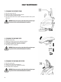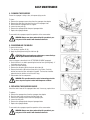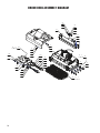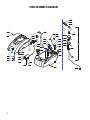
1
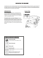
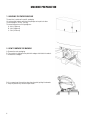
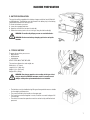
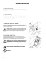
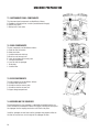
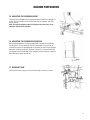
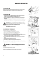
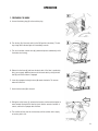
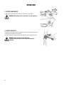
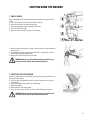
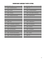
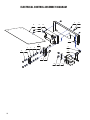
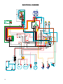
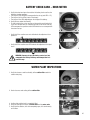
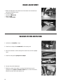
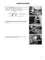
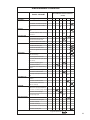
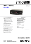
E29951-00
E29952-00
STEALTH ASC24BT
™
24" Cylindrical Scrubber
with Traction Drive
Operator and Parts
Manual
1001 Brown Avenue • Toledo, Ohio 43607-0127
Customer Service: 888-GO-BETCO • Fax: 800-445-5056 • Technical Service: 877-856-5954 • www.betco.com
1
TABLE OF CONTENTS
RECEIVING THE MACHINE............................................. 3
TECHNICAL SPECIFICATIONS......................................... 4
GENERAL SAFETY REGULATIONS.................................. 5
MACHINE PREPARATION.........................................6 - 12
OPERATION...........................................................13 - 14
TURNING OFF THE MACHINE....................................... 15
DAILY MAINTENANCE.............................................16 -17
WEEKLY MAINTENANCE............................................... 18
TROUBLESHOOTING.................................................... 19
BRUSH AND SELECTION USE...................................... 19
PARTS DIAGRAMS AND LISTINGS........................20 - 44
BATTERY CHECK CARD – HOUR METER...................... 45
WATER PLANT INSPECTIONS...................................... 45
BRAKE ADJUSTMENT................................................... 46
VACUUM SYSTEM INSPECTION................................... 46
SQUEEGEE ADJUSTMENT............................................ 47
CHECK LIST.................................................................. 48
MAINTENANCE SCHEDULE.......................................... 49
WEAR ITEMS................................................................ 50
WARRANTY.................................................................. 52
2
RECEIVING THE MACHINE
Immediately check, when receiving the machine, that all the materials indicated on delivery documents have been received and
also that the machine has not been damaged in transit. If it has been damaged, this damage must be immediately reported to
the shipper and also to our customer’s service department. Only acting promptly in this manner will make it possible to receive
missing material and to be compensated for damage.
INTRODUCTION
Serial # Plate
This is an automatic scrubber which, via the mechanical action of the rotating brush and the chemical action of a water/
detergent solution, can clean many types of hard flooring. As
it advances, it also collects the dirt removed and the detergent
solution not absorbed by the floor.
The machine must be used only for this purpose. Even the
best machines will only work well if used correctly and kept in
good working order. We therefore suggest you read this instruction booklet carefully and re-read it whenever difficulties arise
while using the machine. Please contact our technical service
department or your dealers if you have any questions about the
machine.
SYMBOLS USED ON THE MACHINE
Solution valve symbol
Used to indicate the water regulation switch
Battery charge gauge
Battery symbol
Open book symbol
Used to tell the operator to read the manual before
using the machine
Maximum solution temperature gauge
Located near the solution tank inlet
3
TECHNICAL DESCRIPTION Measurement Unit
Stealth™ ASC24BT
Working Width
Inches
24
Work Capacity
Sq. Ft. / Hr.
32,000
Brush Width
Inches
24
Brush RPM
RPM
575
Brush Pressure
Lbs. (Kg)
110 (50)
Brush Motor
V / HP / W
24 / 0.75 / 560
Drive Type
Forward Speed
MPH (km/h)
Maximum Grade
Vacuum Motor
Automatic
1.9 (3)
10%
V / HP / W
24 / 0.5 / 310
Vacuum Motor Suction
Millibar
188
Solution Tank Capacity
Gallons (L)
21 (80)
Recovery Tank Capacity
Gallons (L)
24 (90)
Lbs. (Kg)
385 (175)
V / A
24 / 25
in x in x in
57 x 43 x 26
dBA
58
Weight of Machine (excluding batteries)
Battery Charger
Machine Dimensions (Length/Width/Height)
Noise Level
4
GENERAL SAFETY REGULATIONS
The regulations below must be carefully followed in order to avoid harm to the operator and damage to the machine.
• Read all labels on the machine carefully. Do not cover them for any reason and replace them immediately if they become
damaged.
• The machine must be used exclusively by authorized and trained personnel.
• When operating the machine be careful of other people.
• The machine is not designed for cleaning carpets.
• The power cable outlet must be provided with a proper ground.
• Avoid damaging the power cable of the battery charger by crushing, bending, cutting or stressing it.
• Whenever the power cable of the battery charger is damaged, immediately contact a BETCO service center.
• Do not mix different types of detergent as this may produce harmful gases.
• Do not set containers on the machine.
• Machine storage temperature is between -10°F and 130°F, never store outside under humid conditions.
• Operating conditions: room temperature between 33°F and 100°F with relative humidity between 30% to 95%.
• Only use the machine in closed areas and do not expose it directly to rain.
• Never use the machine in an explosive environment.
• Do not use the machine as a means of transport.
• Never use acidic chemicals which could damage the machine.
• Avoid running the brushes with the machine stopped; this could damage the floor.
• Never vacuum up flammable liquids.
• Never use the machine to gather dangerous powders.
• Use a powder fire extinguisher in case of fire. Do not use water.
• Do not hit against shelving or scaffolding. The operator must always be equipped with the appropriate safety device
(gloves, shoes, helmet, glasses, etc.)
• Do not use the machine on surfaces with an inclination greater than the one shown on the serial plate.
• The machine is designed to wash and dry floors simultaneously. Signal the presence of wet floors with suitable signs.
• If the machine does not work properly, perform routine maintenance. Otherwise, request the assistance of the BETCO technical service.
• When replacing parts ask for ORIGINAL spare parts from your Authorized BETCO Dealer and/or Retailer.
• Always turn off the machine and disconnect the battery connector whenever maintenance is performed.
• Never remove guards that require tools for removal.
• Never wash the machine with direct or pressurized jets of water or with corrosive substances.
• Have your BETCO service center check the machine once a year.
• To prevent the formation of scale in the solution tank filter, do not store the machine with detergent solution in the tanks.
• Before using the machine make sure that all doors and covers are positioned as shown in this operating and maintenance
manual.
• When your BETCO machine is ready to be retired, the machine must be disposed of properly. It contain oils and electronic
components. The machine was built using totally recyclable materials.
• Use only brushes furnished with the machine or those specified in the user's manual. Use of other brushes can compromise safety.
• When removing the battery, unplug the battery connection, unplug the charger and disconnect the battery terminals.
• Before recycling the machine, remove the battery.
5
MACHINE PREPARATION
1. HANDLING THE PACKED MACHINE
The machine is contained in specific packaging.
It is not possible to place more than two packages on top of each other.
The total weight is 735 Lbs. (335 kg).
The overall dimensions of the package are:
A: 69 in (1760 mm)
B: 40 in (1020 mm)
C: 50 in (1270 mm)
2. HOW TO UNPACK THE MACHINE
A. Remove the outer packaging.
B. The machine is attached to the pallet with wedges which block the wheels.
C. Remove these wedges.
D.Use a ramp to get the machine down from the pallet, pulling it backwards.
E. Keep the pallet for any future transport needs.
6
MACHINE PREPARATION
3. BATTERY INSTALLATION
The machine will be supplied with a battery charger and either four 6V Wet Cell
or AGM batteries. The batteries must be housed in the battery tray in the battery
compartment beneath the recovery tank.
To insert the batteries you must:
A. Lower the squeegee and base.
B. Open the rear latch that secures the tank (2).
C. Rotate the recovery tank as far as it will go, using the side handle (3).
WARNING: To avoid acid spillage you can use sealed batteries.
WARNING: Perform one battery charging cycle before using the
machine.
4. TYPE OF BATTERY
To power the machine you can use:
• Wet batteries
• AGM batteries
• Gel batteries
OTHER TYPES MUST NOT BE USED.
The maximum dimensions and weight are:
Width 6.8 in. (172 mm)
Length 14.2 in. (360 mm)
Height 11.2 in. (285 mm)
Weight 97 lb. (44 kg)
WARNING: Your charger must be set according to the type of battery you install. Call BETCO customer service to ensure correct
charger setting after replacement batteries are installed.
• The batteries must be handled using lifting and transportation means suitable
for the weight and dimensions.
• They must be lifted by the handles on the upper part.
• They must be connected together in series, to obtain an overall voltage of 24
V on the lugs.
• The electrical connection operations must be carried out by certified trained
personnel.
7
MACHINE PREPARATION
5. BATTERY MAINTENANCE
For maintenance and recharging, follow the instructions provided by the battery
manufacturer.
6. BATTERY DISPOSAL
When the battery reaches the end of its life, it must be disconnected by certified professional, then lifted (using the handles and suitable lifting device) to
remove it from the battery compartment.
7. CONNECTING THE BATTERY CHARGER
Beneath the recovery tank there is the battery connector (7), the battery charger
connector must be plugged into. Disconnect the battery plug and plug the
charger into the machine plug.
WARNING: This process must be carried out by qualified personnel. The incorrect or imperfect connection of the cables to the
connector can seriously harm people and damage objects.
8. RECHARGING THE BATTERIES
Perform one complete battery charge cycle before using the machine.
Avoid totally discharging the batteries! This can cause permanent damage.
Recharge as soon as the battery discharged signal light starts to flash.
WARNING: Never leave the batteries completely discharged, not
even if the machine is not being used. This can cause permanent damage to them. While recharging, keep the recovery tank
raised.
Danger of inhalation of gas and leakage of corrosive liquids.
Danger of fire.
8
MACHINE PREPARATION
9. CONNECTING THE BATTERY CONNECTOR
Connect the battery connector (2) to the machine connector (1)
10. BATTERY INDICATOR
The battery indicator uses LEDs and has 8 positions (7 yellow - charged batteries, and 1 red - run down batteries).
WARNING: A few seconds after the red indicator light comes on,
the brush motor turns off automatically. The vacuum motor will
remain in operation so that the remaining water can be removed
from the floor.
9
MACHINE PREPARATION
11. INSTRUMENT PANEL COMPONENTS
The instrument panel components are identified as follows:
A. Paddles to activate brushes / traction (located beneath the grip)
B. ON/OFF key switch
C. Battery level / hour meter
12. REAR COMPONENTS
The rear components are identified as follows:
A. Pedal to raise the brushes
B. Water level tube
C. Solution tank water inlet cap
D.Drain hose of recovery tank
E. Latch to lock down the recovery tank
F. Storage compartment
H.Lever to raise the squeegee
I. Brake lever
J. Solution filter
13. SIDE COMPONENTS
The side components are identified as follows:
A. Solution flow control valve
B. Handle to raise the recovery tank
C. Handle to raise the vacuum unit
D.Upper storage compartment
14. ASSEMBLING THE SQUEEGEE
For packaging reasons, the squeegee is supplied disassembled from the machine, and must be assembled as shown in the figure, inserting the small pin of
the squeegee into the coupling mechanism until it locks into place.
Install the squeegee vacuum hose over the squeegee shoe adapter and be certain that the vacuum hose in to the right of the squeegee lift cable.
10
MACHINE PREPARATION
15. ADJUSTING THE SQUEEGEE HEIGHT
The height of the squeegee must be adjusted based on wear of the squeegee. To
do this, turn the knob (2) counter clockwise to raise the squeegee, and clockwise to lower it.
Note: the right and left wheels must be adjusted to the same level, so the
squeegee works parallel to the floor.
16. ADJUSTING THE SQUEEGEE INCLINATION
During working operation, the rear squeegee blade is slightly bent backwards
(by about 0.2 in (5 mm)) uniformly over its entire length. If it’s necessary to
increase the bend of the squeegee blade in the center, you must tilt the squeegee
backwards, rotating the adjuster (1) counter clockwise. To increase the bend of
the squeegee at the outside edges of the squeegee, rotate the adjuster clockwise.
After adjustment, tighten the jam nut.
17. RECOVERY TANK
Check the drain hose cap (on the rear of the machine) to ensure it’s closed.
11
MACHINE PREPARATION
18. SOLUTION TANK
Remove the front inlet cap and check the solution filter is correctly installed.
Check the solution filter cover (beneath the tank) is correctly closed.
19. SOLUTION TANK
• Fill the tank with clean water in the front fill location (1) or at the rear fill
location (2) at a temperature not exceeding 120°F (50°C).
• You can check the level of solution in the tank by means of the rear sight
gauge (3).
• Add the liquid detergent into the tank, in the concentration and manner
specified by the manufacturer. The formation of excess foam could damage
the vacuum motor, so be sure to use only the correct amount of detergent.
WARNING: Always use low-foam detergent. Introduce a small
amount of defoaming liquid in the recovery tank before starting
to work to prevent foam from being generated.
WARNING: Never use pure acids.
20. ASSEMBLING THE BRUSHES
Proceed as follows to assemble the brushes:
1. Use the side parking brake lever to stop the machine.
2. Raise the brush head by means of the appropriate pedal.
3. Make sure that the key switch is in the “0” position.
4. Remove the right-side splash guard by loosening the knob (1).
5. Insert the brush (the side with 5 teeth) in the tunnel until it couples with the
dragging device hub on the opposite side of the tunnel.
6. Insert the idle hub (2) of the mobile support in the brush (the side with 5
teeth).
7. Repeat the operation for the second brush.
8. Reassemble the side splash guard, tightening the knob (1).
Take care how the brushes are mounted, the assembly is correct if the direction
of the bristles form an X looking from above.
WARNING: You are advised to always wear protective gloves in
order to avoid the risk of serious injury to your hands.
21. REGULATING THE SOLUTION
Regulate the quantity of water with the solution control valve (1).
12
OPERATION
1. PREPARING TO WORK
A. Connect the battery plug (1) to the machine plug
B. Turn the key (1) of the main switch to the "ON" position (clockwise). The battery charge level indicator lights will immediately come on.
C. Turn on the solution control valve (2) (solution dispenses automatically while
the brushes are turning).
D.Release the foot lever (3) and lower the brush deck. If the floor is particularly
dirty, you can apply additional pressure to the brush deck by raising the foot
lever (3) until the lock down is engaged.
E. Lower the squeegee, turning the lever (4) counter clockwise. The vacuum
motor will switch on.
F. Check that the brake (5) is released.
G.Pulling the switch levers (1), activates the brushes and the machine begins to
move forward. During the first few feet, check that the amount of solution is
correct, and that the squeegee dries the floor.
H.The machine will now start to scrub and dry until the solution tank is empty
or recovery tank is full.
13
OPERATION
2. REVERSE MOVEMENTS
To move in the reverse direction, push the switch levers (1) forward.
WARNING: When making reverse movements, raise the squeegee.
3. OVERFLOW DEVICE
The machine has a float in the filter basket that activates when the recovery tank
is full and stops airflow into the vacuum.
You must empty the recovery tank by removing the cap of the rear drain hose.
WARNING: Always wear gloves when doing this
operation to protect yourself from contact with hazardous
chemicals.
14
SHUTTING DOWN THE MACHINE
1. END OF WORK
When shutting down the machine and before you perform any type of maintenance:
A. Turn off the solution control valve using the handle (1)
B. Raise the brush deck using the foot lever (2)
C. Raise the squeegee using the squeegee lift lever (3)
D.Turn off the key switch (4)
E. Move the machine where the tanks can be drained.
F. Remove the drain hose from its holder, unscrew the drain cap and empty the
recovery tank.
G.The squeegee must be raised when the machine is not operating, to avoid
deforming the squeegee blade blades.
H.Remove the pads and clean them with water.
WARNING: Always wear gloves when doing this operation to protect yourself from contact with hazardous chemicals.
2. EMPTYING THE DUST HOPPER
Empty the hopper after work and before performing any type of maintenance, to
do so proceed as follows:
A. Push the knob (1) toward the rear of the machine and release the left side
splash guard.
B. Remove the hopper, empty and clean it thoroughly.
C. Return the hopper.
D.Reassemble the side splash guard.
E. Raise the brush head at the end of work to avoid deforming the brushes.
WARNING: Always wear gloves when doing this operation to protect yourself from contact with hazardous chemicals.
15
DAILY MAINTENANCE
1. CLEANING THE RECOVERY TANK
A. Raise the vacuum unit (1).
B. Remove the drain hose (2) and empty the tank.
C. Rinse the inside of the tank with water.
D.Close the vacuum unit on the machine and replace the drain hose cap and
drain hose.
WARNING: Always wear gloves when doing this operation to protect yourself from contact with hazardous chemicals.
2. CLEANING THE VACUUM FILTER
A. Raise the vacuum unit.
B. Remove the vacuum filter cover by rotating it clockwise.
C. Pull the filter straight down from the lid to remove it.
D.Use water to clean the walls and base of the filter.
E. Reassemble all the components.
WARNING: Always wear gloves when doing this operation to protect yourself from contact with hazardous chemicals.
3. CLEANING THE VACUUM HOSE FILTER
A. Raise the vacuum unit.
B. Rotate the inner filter (1) and remove it.
C. Use water to clean the walls and base of the filter.
D.Reassemble all the components.
WARNING: Always wear gloves when doing this operation to protect yourself from contact with hazardous chemicals.
16
DAILY MAINTENANCE
4. CLEANING THE SQUEEGEE
Ensure the squeegee is always clean, to improve drying results.
To clean:
A. Remove the squeegee vacuum hose from the squeegee shoe adapter.
B. Remove the cotter pins that attach the pins of the squeegee shoe.
C. Disassemble the squeegee from its support.
D.Loosen the wing nuts (1).
E. Remove the squeegee band clamp and squeegee blade.
F. Replace the squeegee blades.
To reassemble the squeegee, repeat the operations in the reverse order.
WARNING: Always wear gloves when doing this operation to protect yourself from contact with hazardous chemicals.
5. DISASSEMBLING THE BRUSH
To remove the brushes:
1. Turn the key to position "0" (1).
2. Apply the parking break using the side lever (2).
ATTENTION: Before performing any maintenance, remove the keys
from the panel and disconnect the batteries.
Clean the hopper as described in the "AT THE END OF WORK" paragraph.
3. Check that there is no debris preventing the brushes from spinning freely. If
the brushes are not clean:
4. Loosen the thumb knob (1).
5. Remove the side plate (2) with the brush drive hubs (3).
6. Remove the brushes (4) and clean them with a jet of water. Check the
bristles for excessive wear and replace if needed. The brushes should be
replaced when the bristles are less than 0.5" long.
7. Reassemble all of the components.
WARNING: This operation must be carried out wearing protective
gloves to protect against contact with dangerous solutions.
6. REPLACING THE SQUEEGEE BLADES
Check the state of wear of the squeegee blades and, if necessary, replace them.
To replace:
A. Remove the squeegee hose from the squeegee shoe adapter.
B. Push the release lever and release the right hand stud.
C. Remove the squeegee vacuum from the squeegee yoke.
D.Loosen the wing nuts.
E. Remove the squeegee band clamp and squeegee blade.
F. Replace the squeegee blades.
To reassemble the squeegee, repeat the operations in the reverse order.
WARNING: Always wear gloves when doing this operation to protect yourself from contact with hazardous chemicals.
17
WEEKLY MAINTENANCE
1. CLEANING THE SQUEEGEE HOSE
Every week, or whenever vacuum seems to be unsatisfactory, check the squeegee hose for obstructions. To clean:
A. Remove the hose from the squeegee shoe adapter on the squeegee shoe.
B. Remove the other end from the recovery tank.
C. Wash the inside of the hose with water from the end of the hose which is
connected to the recovery tank.
D.Reassemble the hose.
WARNING: Always wear gloves when doing this operation to protect yourself from contact with hazardous chemicals.
2. CHECKING THE BRAKE
Every week, check the distance between the brake pads and the wheels. If necessary, adjust them, so the pads are 0.12 inches away from the transport wheels at
a distance of 0.12 in (3 mm) when released.
3. CLEANING THE SOLUTION TANK
A. Loosen the solution tank cap.
B. Rinse with water.
C. Loosen the drain cap (1) located on the filter, and empty the tank.
WARNING: Always wear gloves when doing this operation to protect yourself from contact with hazardous chemicals.
18
TROUBLESHOOTING GUIDE
INSUFFICIENT WATER ON THE PAD
1. Verify that the solution control valve – located beneath the symbol – (1) is
turned on.
2. Verify that there is water in the solution tank.
THE MACHINE DOES NOT CLEAN WELL
1. Check the state of wear of the scrubbing pad and, if necessary, replace it.
2. Use a different kind of scrubbing pad.
THE SQUEEGEE DOES NOT DRY THE FLOOR
1. Ensure that the squeegee blades are clean.
2. Adjust the inclination of the squeegee.
3. Ensure the vacuum hose is correctly installed.
4. Check the inner filter of the recovery tank to ensure it is not dirty and, if necessary, clean it thoroughly.
5. Disassemble the entire vacuum unit and clean it.
6. Replace the squeegee blades, if worn.
7. Ensure the vacuum motor is turned on.
8. Check squeegee wheel adjustment.
TOO MUCH FOAM IS GENERATED
Check that low-foam detergent is being used. If necessary add a small amount of defoamer liquid to the recovery tank.
Remember that more foam is generated when the floors are not very dirty. Dilute the detergent more when cleaning floors that
are not very dirty.
CHOOSING AND USING THE BRUSHES
POLYPROPYLENE BRUSH (PPL)
Used on all types of floors. Good resistance to wear and tear, and hot water (no greater than 140°F (60°C)).
NYLON BRUSH
Used on all types of floors. Excellent resistance to wear and tear and hot water (even over 140°F (60°C)).
ABRASIVE BRUSH
The bristles of this type of brush are coated with highly aggressive abrasives. It is used to clean very dirty floors. To avoid floor
damage work only with the brush pressure necessary.
THICKNESS OF THE BRISTLES
Thicker bristles are more rigid and are therefore used on smooth floors or floors with small joints. On uneven floors or those with
deep joints, it is advisable to use softer bristles which can enter the gaps easier. When the bristles are worn and too short, they
will become rigid and are no longer able to penetrate and clean deep down and the brushes tends to jump.
PAD DRIVER
Pad Holders and scrub pads are recommended for cleaning smooth surfaces. There are two types of pad holder:
1. The traditional pad holder has a series of anchor points that allow the abrasive floor pad to be held and dragged while working.
2. The CENTER LOCK type pad holder not only has anchor points, but also a snap-type central locking system made of plastic
that allows the abrasive floor pad to be centered and held without any risk of it becoming detached. This type of pad driver is
recommended above all for machines with more than one brush.
19
BRUSH DECK ASSEMBLY DIAGRAM
2.3
2.5
2.5
2.2
2.8
2.1
2.5
2.4
2.9
2.6
2.7
5
15
8
1.18
4
13
3
5
4
1.16
1.14
1.9
1.12
1.5
1.2
16
17
1.1
1.3
10
6
1.13
1.4
1.11
1.15
1.17
12
20
14
1.8
1.7
1.10
9
1.6
11
7
BRUSH DECK ASSEMBLY PARTS LISTING
Item# Part # Description
Qty.
Item# Part # Description
Qty.
1.1
E83434 Brush Hub
2
2.4
E22507 Nut, M6 x 8
1
1.2
E83435 Pin / Shaft
2
2.5
E83799 Flat Washer M6.6x18x2 SS
3
1.3
E22197 Side Plate
1
2.6
E86275 Barbed Elbow, 3/8"
1
1.4
E83580 Ring
2
2.7
E81944 Grommet
1
1.5
E83439 Oil seal DRS/CRS
2
2.8
E22508 Blade
1
1.6
E83436 Seeger ring
DRS/CRS
2
2.9
E22509 Filter
1
1.7
E83437 Retaining Ring - External
2
3
E22510 Brush Base Assembly
1
1.8
E22181 Bearing, 6202 2RS 15x35x11
2
4
E83850 Flat Washer M5x20 SS
8
1.9
E83835 Screw M6 x 12
4
5
E20290 Flat Hd Soc Machine Screw M5x16 SS
8
1.1
E83441 Screw
2
6
E22511 Flat Hd Soc Machine Screw M6x16
4
1.11
E81934 Flat Washer M6x12x1.6 SS
4
7
E22512 Brush, General Purpose, 0.4mm
2
1.12
E22199 Cupped Washer
2
8
E22513 Side Squeegee, 40 SH Gum Rubber
1
1.13
E83438 Cover DRS/CRS
2
9
E22513 Side Squeegee, 40 SH Gum Rubber
1
1.14
E22500 Knob
1
10
E22201 Retaining Blade
1
1.15
E20323 Lock Washer M6 SS
4
11
E22516 Brush, Medium Duty, 0.6mm
2
1.16
E22501 Retaining Blade
1
12
E22517 Brush, Tynex Grit, 0.9mm
2
1.17
E22502 Screw, M6 x 10
4
13
E22518 Base Cover
1
1.18
E22503 Side Squeegee, 30 SH Gum Rubber
1
14
E22503 Side Squeegee, 30 SH Gum Rubber
1
2.1
E22505 Debris Hopper
1
15
E22520 Side Squeegee, 40 SH Poly
1
2.2
E22506 Bolt, M6 x 30
1
16
E22520 Side Squeegee, 40 SH Poly
1
2.3
E88024 Spring CM 70 HS
1
17
E22522 Retaining Blade
1
DRS/CRS
21
BRUSH BASE ASSEMBLY DIAGRAM
95
39
73
63
58
94
39
74
77
91
5
16
39
63
19
48
37
79
57
73
30
39
90
57
92
74
55
58
67
52
73
41
29
73
20.162
20.2
77
87
61
70
86
8
32
68
44
2
42
13
39
28
5
27
59
1
96
59
33
3
28
26
73
74
50
5
38
59
1
27
48
22
83
18
39
47
18
5
73
64
15
10
89
60
56
81
17
40
11
85
9
74
24
38
64
40
28
78
74
83
5
80
8
11
38
24
57
57
66
22
73
45
54
49
75
38
55
51
53
72
24
10
73
60
73
5
74
4
50
34
14
73
88
43
35
25
69
95
20.3
57
74
44
76
20.6
58
7
46
93
65
70
5
81
23
20.4
21
12
36
31
5
6
74
74
5
28
82
20.5
BRUSH BASE ASSEMBLY PARTS LISTING
Item# Part # Description
Qty.
Item# Part # Description
Qty.
1
E83274 Support
2
47
E83831 Flat Hd Soc Machine Screw M6x20 SS
1
2
E22523 Stop
2
48
E22511 Flat Hd Soc Machine Screw M6x16
5
3
E81778 Spring
1
49
E22547 Screw
2
4
E82701 Tube
2
50
E83947 Hex Nut, M6x5 SS
2
5
E83469 Washer
9
51
E20113 Hex Jam Nut, M6X4 SS
2
6
E22524 Pulley
1
52
E85499 Hex Nut, M8x6.5 SS
2
7
E22525 Female Coupling
1
53
E20117 Nyloc Hex Jam Nut, M6x9 SS
2
8
E20206 Bushing
2
54
E81342 Nyloc Hex Jam Nut, M8 SS
2
9
E22526 Pulley
1
55
E20119 Nyloc Hex Nut, M8 SS
4
10
E22527 Hub
2
56
E22548 Cage Nut
4
11
E22528 Shaft
2
57
E81934 Flat Washer M6x12x1.6 SS
5
12
E22529 Pulley
1
58
E83799 Flat Washer M6.6x18x2 SS
4
13
E22530 Pin
1
59
E20125 Flat Washer M8x17x1.6 SS
8
14
E22531 Pulley
1
60
E86164 Flat Washer M9x24x2.5 SS
4
15
E22532 Pin
1
61
E81751 Washer
2
16
E22533 Support
1
62
E22199 Cupped Washer
4
17
E22534 Pin
1
63
E22549 Shim
2
18
E22535 Support
1
64
E87289 Shim Washer M20x28x0.3
2
19
E22536 Pulley
1
65
E82260 Carbon Brush
4
20.1
E22158 Sheath
1
66
E20129 Cap
2
20.2
E22538 Stud Bolt
1
67
E22550 Rubber Cap
1
20.3
E82738 Brush Motor 24VDC 560W
1
68
E22551 Elbow
1
20.4
E83801 Hex Bolt M8x35 Zinc
1
69
E86275 Barbed Elbow, 3/8"
1
20.5
E83656 Hex Nut, M8x6.5 Zinc
1
70
E22552 Elbow
2
20.6
E83935 Wire Tie
3
71
E22553 Carbon Brush Holder
1
21
E22539 Spacer
1
72
E20322 Hex Nut, M5 SS
1
22
E22540 Cover
1
73
E82314 Nyloc Hex Nut, M6 SS
14
23
E22541 Brush Base
1
74
E20323 Lock Washer M6 SS
15
24
E83276 Washer
4
75
E20299 Loop Clamp
2
25
E83580 Ring
2
76
E22554 Screw
1
26
E83896 Wheel
2
77
E81896 Carriage Bolt M6x16 SS
3
27
E82451 Wheel 45 OD x 25 W
4
78
E22555 Washer
1
28
E83279 Screw
4
79
E22556 Blade
1
29
E20087 Hex Bolt M6x16 SS
1
80
E22557 Belt
1
30
E83914 Hex Bolt M6x20 SS
1
81
E22558 Shim
2
31
E22506 Screw
1
82
E22559 Belt
1
32
E82396 Spacer
2
83
E22560 Screw
2
33
E83524 Bushing
2
84
E22561 Screw
1
34
E22542 Spring
1
85
E22502 Screw, M6 x 10
6
35
E83436 Seeger Ring
1
86
E22562 Hose
1
36
E82449 Key
1
87
E22563 T-Fitting
1
37
E83700 Shaft Key 5x5x20mm
1
88
E22564 Screw
4
38
E22181 Bearing
4
89
E22565 Screw
2
39
E82764 Bearing Sweeper
7
90
E22566 Shaft Key 5x3x20mm
1
40
E83923 Bearing, 6004 2RS
2
91
E22567 Shaft
1
41
E22544 O-Ring
1
92
E22568 Pulley
1
42
E89630 O-Ring
2
93
E22569 Tube
1
43
E20234 Carriage Bolt M6x20 SS
2
94
E22570 Mounting Bracket
1
44
E22545 Screw
3
95
E22571 Screw
2
45
E22546 Screw
1
96
E22572 Spacer
1
46
E83671 Hex Bolt M8x30 SS
2
23
DECK LIFT ASSEMBLY DIAGRAM
24
32
31
32
4
34
3
6
24
13
18
30
16
28
28
20
26
1
33
19
25
23
30
12
26
10
27
25
22
14
25
16
2
15
28
29
11
28
11
28
25
27
28
11
8
28
9
17
21
25
5
28
25
25
35
24
28
28
11
16
28
28
16
11
DECK LIFT ASSEMBLY PARTS LISTING
Item# Part # Description
Qty.
Item# Part # Description
Qty.
1
E20220 Brush Deck Lift Arm Linkage
1
19
E22289 Hex Bolt M10x50 Zinc
1
2
E22573 Bushing
1
20
E20112 Hex Nut, M6x6 Zinc
1
3
E22574 Lever
1
21
E83852 Hex Nut, M6x5
1
4
E22575 Spacer
1
22
E82808 Hex Jam Nut, M8X5 Zinc
1
5
E22576 Arm
1
23
E81673 Hex Nyloc Nut, M3 Zinc
2
6
E22577 Lever
1
24
E83550 NyLoc Hex Nut, M6 Zinc
2
7
E88279 Micro Switch Sealed
1
25
E86853 Nyloc Hex Nut, M8 Zinc
7
8
E22578 Arm
1
26
E83381 Nyloc Hex Nut, M10 Zinc
2
9
E20088 Hex Bolt M6x18 Zinc
1
27
E81874 Flat Washer M8x17x1.6 Zinc
3
10
E20090 Hex Bolt M6x25 Zinc
1
28
E83404 Flat Washer M9x24x2.5 Zinc
17
11
E83932 Bushing
5
29
E83704 Lock Washer M8x13x2.2 Zinc
1
12
E82285 Bushing
2
30
E82773 FI1241-Flat Washer M10x21x2 Zinc
2
13
E22579 Bushing
1
31
E88782 Gas Shock Absorber
1
14
E22580 Spring
1
32
E22581 Spring
2
15
E83833 Hex Bolt M8x25 Zinc
1
33
E20533 Hex Bolt M3x20 SS
2
16
E83802 Hex Bolt M8x30 Zinc
4
34
E20635 Abrasive Antislip Tape
1
17
E83801 Hex Bolt M8x35 Zinc
1
35
E22582 Spring
2
18
E83830 Hex Bolt M8x40 Zinc
1
25
SQUEEGEE ASSEMBLY DIAGRAM
22
22
1
15
9
2
18
14
16
15
10
10
3
13
18
16
7
21
11
19
17
12
5
20
17
10
9
10
6
11
26
4
13
8
SQUEEGEE ASSEMBLY PARTS LISTING
Item# Part # Description
Qty.
Item# Part # Description
Qty.
1
E89559 Squeegee Vacuum Adapter (H)
1
12
E22352 Center Front Squeegee Blade Clamp
1
2
E82275 Pin, Adjustable Mounting M10 Zinc
1
13
E22354 Outer Front Squeegee Blade Clamp
2
3
E82280 Pin, Fixed Mounting M10 Zinc
1
14
E22355 Center Rear Squeegee Blade Clamp
1
4
E22351 Squeegee Body 42.5 Inch ASM
1
15
E22357 Outer Rear Squeegee Blade Clamp
2
5
E88442 Bushing, Steel, 12mm OD, 8mm ID, 28mm L
2
16
E86255 Flat Washer M10x21x2 SS
2
6
E22358 Wing Nut Knob
13
17
E86164 Flat Washer M9x24x2.5 SS
4
7
E22359 Wing Nut Knob
13
18
E20128 Lock Washer M10 SS
2
8
E88953 Squeegee Blade Kit, 42.75"
1
19
E20252 Lock Washer M8x13x2.2 SS
2
9
E88953 Squeegee Blade Kit, 42.75"
1
20
E88280 Wheel 80 OD x 23 W
2
10
E22385 O-Ring 7mm
52
21
E20287 Hex Bolt M8x45 SS
2
11
E22346 Custom Cap Screw
26
22
E22630 Thumb Screw
2
27
SQUEEGEE SUPPORT ASSEMBLY DIAGRAM
3.25
3.30
3.1
3.10
3.26
3.16
3.11
10
17
3.32
3.3
2
3.15
3.18
9
3.4
16
3.12
3.7
3.2
1
3.14
6
3.21
4
3.23
5
3.29
3.26
3.34
3.9
18
3.8
3.5
3.19
3.17
12
3.27
11
3.33
3.18
3.23
3.6
3.31
4
28
15
3.22
3.31
19
7
3.33
3.27
3.20
3.35
3.13
3.28
8
3.24
14
13
SQUEEGEE SUPPORT ASSEMBLY PARTS LISTING
Item# Part # Description
Qty.
Item# Part # Description
Qty.
1
E20313 Squeegee Lift Lever
1
3.26
E20121 Flat Washer M5x15x1.5 Zinc
2
2
E88279 Micro Switch Sealed
1
3.27
E82761 Flat Washer M6x12x1.6 Zinc
6
3.1
E22583 Support
1
3.28
E83278 Flat Washer M6.5x24x2 Zinc
2
3.2
E20010 Pivot Pin
1
3.29
E82774 Lock Washer, M6 Zinc
2
3.3
E82265 Knob, Squeegee Pitch Adjustment
1
3.3
E20125 Flat Washer M8x17x1.6 SS
1
3.4
E83331 Knob, M8 Round Nylon Female
2
3.31
E85722 Flat Washer M13x24x2.5 Zinc
2
3.5
E85776 Pivot Connector
1
3.32
E81406 External Serrated Lock Washer M13x18 Zinc
1
3.6
E20078 Squeegee Wheel Support
2
3.33
E82314 Nyloc Hex Nut, M6 SS
3
3.7
E81880 Squeegee Yoke
1
3.34
E20382 Nyloc Hex Nut, M5 x 5 Zinc
1
3.8
E20079 Threaded Adjuster Rod
2
3.35
E88280 Wheel 80 OD x 23 W
2
3.9
E20080 Ballast
2
4
E20337 Flat Washer M17x40x2 Delrin
2
3.1
E86252 Latch, Squeegee Connector
1
5
E20231 Bushing
1
3.11
E83881 Hex Bolt M5x20 Zinc
1
6
E82455 Hex Bolt M10x35 Zinc
1
3.12
E20090 Hex Bolt M6x25 Zinc
2
7
E83838 Screw, Flat Hd M4x15 Zinc
4
3.13
E82274 Bushing
2
8
E83535 Hex Nut, M5x5 Zinc
1
3.14
E20091 Spring
2
9
E82317 Hex Jam Nut, M5X3.5 Zinc
1
3.15
E82703 Spring, 16.6x2x23mm Compression
1
10
E81673 Hex Nyloc Nut, M3 Zinc
2
3.16
E82453 Spring, 10x1.1x38 SS Extension
1
11
E83381 Nyloc Hex Nut, M10 Zinc
1
3.17
E86158 Spring, 86mm Torsion Custom
1
12
E20295 Flat Washer M10.5x32x4Zinc
1
3.18
E85498 E Style Circlip
2
13
E83538 Fork WS17
1
3.19
E86159 Hex Bolt M6x50 Zinc
1
14
E83542 Clip WS17
1
3.2
E83866 Hex Bolt M6x60 SS
2
15
E20533 Hex Bolt M3x20 SS
2
3.21
E20098 Hex Bolt M8x18 Zinc
1
16
E20382 Nyloc Hex Nut, M5 x 5 Zinc
1
3.22
E83672 Hex Jam Nut, M8x5 SS
2
17
E20638 Knob
1
3.23
E83824 Square Nut, M8 SS
3
18
E88250 Squeegee Lift Cable
1
3.24
E83550 NyLoc Hex Nut, M6 Zinc
2
19
E20641 Bracket
1
3.25
E86853 Nyloc Hex Nut, M8 Zinc
1
29
FRAME ASSEMBLY DIAGRAM
9
22
25
10
29
30
15
31
26
11
15
6
36
37
4
16
44
12.8
29
25
33
18
38
12.13
24
34
17
27
13
3
28
14
43
16
39
30
42
2
12.3
12.11
40
26
18
46
12.4
35
20
1
12.12
12.5
12.7
32
8
34
5
38
12.9
45
19
41
23
12.10
21
3
12.2
7
24
25
12.8
12.1
12.6
FRAME ASSEMBLY PARTS LISTING
Item# Part # Description
Qty.
Item# Part # Description
Qty.
1
E82689 Spring, 15x2x60mm Galv Extension
1
18
E81917 Bolt, Hex, M8x20, Zinc
5
2
E82395 Washer
2
19
E22592 Screw, M6 x 35
4
3
E22584 Spacer
2
20
E20390 Soc Hd Cap Screw M8x22 Zinc
2
4
E20609 Bearing Mount Base
2
21
E20111 Flat Hd Soc Machine Screw M6x20 Zinc
3
5
E20014 Bearing Mount Cap
2
22
E83835 Screw M6 x 12
4
6
E22585 Frame
1
23
E20247 Flat Hd Soc Machine Screw M8x18 Zinc
2
7
E22586 Rocker Arm, Left
1
24
E82808 Hex Jam Nut, M8X5 Zinc
2
8
E22587 Rocker Arm, Right
1
25
E83550 NyLoc Hex Nut, M6 Zinc
4
9
E22588 Pad
1
26
E86853 Nyloc Hex Nut, M8 Zinc
6
10
E22537 Battery Tray
1
27
E20250 Cage Nut M5
2
11
E22590 Support
1
28
E81618 Flat Washer M5x10x1 SS
2
12
E20518 Brake Lever ASM
1
29
E82761 Flat Washer M6x12x1.6 Zinc
3
12.1
E20595 Brake Lever
1
30
E82798 Flat Washer, M6x18x1.5 Zinc
6
12.2
E20522 Brake Lever Bracket
1
31
E82774 Lock Washer, M6 Zinc
6
12.3
E81928 Latch Lock
1
32
E81874 Flat Washer M8x17x1.6 Zinc
4
12.4
E82255 Spring 4.7x0.5x20mm Compression
1
33
E83404 Flat Washer M9x24x2.5 Zinc
1
12.5
E20341 Hex Bolt M4x16 Zinc
1
34
E83704 Lock Washer M8x13x2.2 Zinc
5
12.6
E83974 Hex Bolt M6x30 Zinc
1
35
E82760 Washer, M8
2
12.7
E81917 Bolt, Hex, M8x20, Zinc
1
36
E22593 Bearing
1
12.8
E20112 Hex Nut, M6x6 Zinc
2
37
E22594 Flange
2
12.9
E22591 Lock Nut, M4 x 6
1
38
E22322 Soc Hd Cap Screw M8x70 Zinc
4
12.10
E83550 NyLoc Hex Nut, M6 Zinc
1
39
E20175 Brake Pad M8x17
2
12.11
E86853 Nyloc Hex Nut, M8 Zinc
1
40
E20176 Band Clamp
1
12.12
E88376 Knob Hole 5 x 20
1
41
E22595 Traction Motor, 250W
1
12.13
E20537 Brake Cable
1
42
E22596 Wheel
2
13
E20084 Hex Bolt M5x16 SS
2
43
E22597 Axle Shaft, Left
1
14
E20088 Hex Bolt M6x18 Zinc
1
44
E22598 Axle Shaft, Right
1
15
E82772 Hex Bolt M6x20 Zinc
6
45
E22599 Splash Guard
1
16
E81657 Bearing, 6204 2RS
2
46
E22600 Caster Wheel
1
17
E88239 Screw
2
31
TANK ASSEMBLY DIAGRAM
19.8
19.9
19.7
A
16
17
8
18
1.5
1.6
1.2
2.8
5
2.5
6
2.4
9
8
2.1
2.7
2.2
A
15
7
19.2
19.4
19.1
19.3
19
19.5
2.9
3
10
4
11
12
13
2.6
32
19.6
2.3
1.4
14
19.4
6
1.7
1.1
1.3
9
19.1
TANK ASSEMBLY PARTS LISTING
Item# Part # Description
Qty.
Item# Part # Description
Qty.
1.1
E20107 Screw, Pan Hd Phil Self Tap M4.2x16 SS
2
8
E82808 Hex Jam Nut, M8X5 Zinc
2
1.2
E20432 Hose Clamp
1
9
E20127 Flat Washer M9x18x1.5 Zinc
2
1.3
E81619 Cable Tie Holder
1
10
E85762 Hose Clamp
2
1.4
E20468 Flat Hd Phil Machine Screw M5x12 Zinc
1
11
E86275 Barbed Elbow, 3/8"
1
1.5
E12633 Latch & Hook ASM
1
12
E20651 Tee Fitting
1
1.6
E88286 Hose, Drain
1
13
E82269 Barbed Fitting, 3/8 in.
1
1.7
E22601 Recovery Tank
1
14
E20190 Spacer Block
2
2.1
E82429 Cap
1
15
E22606 Plate
2
2.2
E82612 Filter
1
17
E22074 Plug, Vac Lid Bale
2
2.3
E20107 Screw, Pan Hd Phil Self Tap M4.2x16 SS
2
18
E22072 Bale, Vac Lid
1
2.4
E81619 Cable Tie Holder
3
19
E22608 Vacuum Hose Assembly
1
2.5
E20468 Flat Hd Phil Machine Screw M5x12 Zinc
3
19.1
E85762 Hose Clamp
2
2.6
E20627 Plug, 3/8" Male
1
19.2
E22609 Flange
1
2.7
E82269 Barbed Fitting, 3/8 in.
1
19.3
E82606 Hose
1
2.8
E20185 Cap
1
19.4
E83920 Clamp 9x300 4,8x360 black
2
2.9
E22602 Solution Tank
1
19.5
E82478 Hose, Vacuum Media
1
3
E22603 Solution Hose
1
19.6
E88499 Hose, Vacuum
1
4
E22604 Solution Hose
1
19.7
E85763 Connector
1
5
E22605 Cable
1
19.8
E22610 Ring Nut
1
6
E83833 Hex Bolt M8x25 Zinc
2
19.9
E82341 Gasket
1
7
E20107 Screw, Pan Hd Phil Self Tap M4.2x16 SS
4
33
VACUUM LID ASSEMBLY DIAGRAM
2.24
2.11
2.13
2.14
2.9
2.3
1
2.18
2.17
2.10
4
2.23
2.15
2.16
2.7
2.30
2.19
2.12
2.8
2.26
2.1
2.28
3
2.4
2.25
2.2
2.21.2
2.6
2.21.1
2.22
2.21.3
2.21.4.2
2.5
34
2.21.4.1
2.21.4
2.21
VACUUM LID ASSEMBLY PARTS LISTING
Item# Part # Description
Qty.
Item# Part # Description
Qty.
1
E20265 Plate
2
2.17
E20182 Sound Deadening Foam
1
2.1
E20305 Mounting Ring
1
2.18
E22519 Gasket
1
2.2
E20652 Sound Deadening Foam
1
2.19
E22075 Hook, Vac Lid Bale
1
2.3
E20180 Sound Deadening Foam
1
2.21
E88291 Vacuum Motor 24VDC 310W
1
2.4
E20179 Sound Deadening Foam
1
2.21.1 E83897 Connector, Electrical Housing 30A
2
2.5
E20178 Sound Deadening Foam
1
2.21.2 E83883 Lug, Electrical 30A
2
2.6
E20266 Sound Deadening Foam
1
2.21.3 E83935 Wire Tie
2
2.7
E88292 Filter, Cage
1
2.21.4.2 E22624 Carbon Brush - Vacuum Motor
2
2.8
E22076 Screw, M4 x 10
2
2.22
E81006 Vacuum Splash Guard
1
2.9
E20384 Vacuum Motor Cover
1
2.23
E20122 Flat Washer M5 x 15 x 1.5 SS
5
2.1
E20191 Deflector
1
2.24
E88290 Hose, Vacuum 1-1/2" x 22-1/4"
1
2.11
E20199 Recovery Tank Cover
1
2.25
E20440 Sound Deadening Foam
1
2.12
E81710 Hose Clamp
1
2.26
E22381 Screw, Pan Hd Phil Self Tap M4.2x16 SS
2
2.13
E82695 Clamp 44-56x12.2
2
2.28
E20106 Screw, Pan Hd Phil Self Tap M4.2x13 SS
2
2.14
E20181 Sound Deadening Foam
1
2.3
E20084 Hex Bolt M5x16 SS
5
2.15
E20184 Sound Deadening Foam
1
3
E22382 Screw, Pan Hd Phil Self Tap M4.2x16 SS
4
2.16
E20183 Sound Deadening Foam
1
4
E20298 Soc Button Head Screw M5x16 SS
1
35
SOLUTION ASSEMBLY DIAGRAM
14
8.2
21
8.1
19
25
10
23
12
17
3
22
15
6.2
16
6.4
7
5
6.3
19
6.1
1
19
19
5
18
9
19
11
4
13
20
2
19
5
18
36
SOLUTION ASSEMBLY PARTS LISTING
Item# Part # Description
Qty.
Item# Part # Description
Qty.
1
E20004 Tubing 12 ID x 200 L
1
10
E82322 Solenoid Valve, 24v 10w 3-Port Nylon
1
2
E81348 Hose
1
11
E83858 Oval Hd SL Machine Screw M4x12 SS
1
3
E82693 Hose, 17 OD x 12 ID x L 420
1
12
E83617 O-Ring, 14x2.5mm Buna-N
1
4
E22612 Spacer
1
13
E20098 Hex Bolt M8x18 Zinc
1
5
E82447 Fitting, 1/2" NPT & 1/2"" Barbed Nylon
3
14
E83838 Screw, Flat Hd M4x15 Zinc
4
6
E88207 Filter Assembly, Inline Double Female 1/2" NPT 1
15
E86853 Nyloc Hex Nut, M8 Zinc
1
6.1
E20512 Filter, Body
1
16
E81874 Flat Washer M8x17x1.6 Zinc
1
6.2
E20144 Cap
1
17
E20253 Flat Washer M21x60x3 Nylon
2
6.3
E88218 Filter Cartridge
1
18
E22611 Hose Clamp
3
6.4
E20145 O-Ring
1
19
E85762 Hose Clamp
6
7
E20457 Bracket
1
20
E82366 Valve
1
8
E20463 Instrument Panel ASM
1
21
E81446 Fitting, 1/2" NPT & 1/2" Barbed Nylon Elbow
1
8.1
E20332 Panel
1
22
E83882 Cap, 1/2" NPT
1
8.2
E88293 Battery Check Card, Hour Meter
1
23
E20433 Ring Nut 1/2"
1
9
E82705 Valve Lever
1
25
E83499 Hose Clamp
1
37
HANDLEBAR ASSEMBLY DIAGRAM
20
1.1
7
10
1.4
23
21
1.2
1.3
9
19
3.15
1.5
3.6
25
24
3.10
27
26
3.9
3.14
3.1
3.17
4
22
38
12
6
3.17
3.16
15
16
3.2
3.7
2
5
8
3.13
18
11
3.8
3.5
17
14
3.3
13
3.12
3.11
3.4
HANDLEBAR ASSEMBLY PARTS LISTING
Item# Part # Description
Qty.
Item# Part # Description
Qty.
1
E82351 Key Switch Assembly w/Keys
1
4
E22615 Pin
2
1.1
E83173 Contact, Key Switch
1
5
E83836 Hex Bolt M5x16 Zinc
1
1.2
E83316 Key Switch
1
6
E20288 Soc Hd Cap Screw M8x30 Zinc
4
1.3
E83316 Key Switch
1
7
E20242 Pan Hd Phil Machine Screw M3x20 Zinc
2
1.4
E81358 Switch Flange
1
8
E88042 Flat Hd Soc Machine Screw M6x16 Zinc
2
1.5
E83315 Switch Key (1)
1
9
E20346 Flat Hd Soc Machine Screw M8x25 SS
2
2
E22613 Electrical Control Panel Assembly
1
10
E81673 Hex Nyloc Nut, M3 Zinc
2
3.1
E20330 Ball Stud M10x22.5
2
11
E20121 Flat Washer M5x15x1.5 Zinc
2
3.2
E20574 Bushing
1
12
E81874 Flat Washer M8x17x1.6 Zinc
4
3.3
E20556 Plate
1
13
E83959 Circuit Breaker 20A
1
3.4
E81763 Cam
1
14
E20298 Soc Button Head Screw M5x16 SS
1
3.5
E88204 Spring
1
15
E81046 Lock Washer M8 Zinc
7
3.6
E20341 Hex Bolt M4x16 Zinc
1
16
E20614 Soc Hd Cap Screw M8x20 Zinc
3
3.7
E20243 Pan Hd Phil Machine Screw M3x30 Zinc
4
17
E88299 Cover, Thermal Switch
1
3.8
E20248 Hex Nut, M4x4 Zinc
1
18
E20576 Cap, M10x13 Threaded Poly
1
3.9
E82317 Hex Jam Nut, M5X3.5 Zinc
2
19
E22616 Circuit Breaker
1
3.10
E81673 Hex Nyloc Nut, M3 Zinc
4
20
E88300 Lever, Left Switch
1
3.11
E83550 NyLoc Hex Nut, M6 Zinc
1
21
E88301 Lever, Right Switch
1
3.12
E82798 Flat Washer, M6x18x1.5 Zinc
1
22
E22617 Door
1
3.13
E82270 Micro Switch
4
23
E88267 Switch Cam
1
3.14
E81625 Shank, M5x32 Female Threaded Nylon
2
24
E22618 Handle Bar
1
3.15
E20360 Hex Bolt M6x45 Zinc
1
25
E88408 Knob
1
3.16
E20362 Set Screw Hex Soc Dog Point M5x30 Zinc
1
26
E22619 Nut
2
3.17
E20382 Nyloc Hex Nut, M5 x 5 Zinc
2
27
E22620 Hose Clip
1
39
ELECTRICAL CONTROL ASSEMBLY DIAGRAM
17
23
19
21
22
18
9
1
20
11
12
7
6
8
5
15
14
13
4
16
40
10
2
3
ELECTRICAL CONTROL ASSEMBLY PARTS LISTING
Item# Part # Description
Qty.
Item# Part # Description
Qty.
1
E22194 Mounting Plate
1
13
E20484 Fuse Block
1
2
E20536 Buss Bar
1
14
E83170 Fuse, 80 Amp
1
3
E83628 Remote control switch
2
15
E20448 Bracket
1
4
E20097 Hex Bolt M8x40 SS
2
16
E20129 Cap
4
5
E20248 Hex Nut, M4x4 Zinc
2
17
E20468 Flat Hd Phil Machine Screw M5x12 Zinc
6
6
E83672 Hex Jam Nut, M8x5 SS
2
18
E81998 Pan Hd Phil Machine Screw M4x10 SS
3
7
E20115 Hex Nut, M8x6.5 Brass
4
19
E20382 Nyloc Hex Nut, M5 x 5 Zinc
4
8
E20479 Spring Nut M5
2
20
E20475 Lock Washer M4 Zinc
2
9
E22195 Washer
3
21
E20301 Flat Hd Phil Machine Screw M4x20 Zinc
2
10
E82761 Flat Washer M6x12x1.6 Zinc
2
22
E82569 Variable Speed Controller
1
11
E20124 Flat Washer M8x17x1.6 SS
6
23
E88456 Electrical Cover Rubber Flap
1
12
E20252 Lock Washer M8x13x2.2 SS
2
41
ELECTRICAL DIAGRAM
42
ELECTRICAL LISTING
Item# Part # Description
Item# Part # Description
2
E82351 Key Switch Assembly w/Keys
16
E82569 Variable Speed Controller
3
E88293 Battery Check Card, Hour Meter
17
E83952 Circuit Breaker 30A
5
E11410 SB175 Red Electrical Connector
17A
ET1002 Part Placeholder for Fimap Parts - FI1241
6
E11410 SB175 Red Electrical Connector
18
E88249 Micro Switch
7
E83170 Fuse, 80 Amp
19
E88249 Micro Switch
8
E83628 Remote Control Switch
20
E20402 Electrical Connector 30A
9
E83628 Remote Control Switch
21
E20402 Electrical Connector 30A
10
E82322 Solenoid Valve, 24v 10w 3-Port Nylon
22
E83959 Circuit Breaker 20A
11
E82270 Micro Switch
M1
E22595 Traction Motor, 250W
12
E82270 Micro Switch
M2
E82738 Brush Motor 24VDC 560W
13
E82270 Micro Switch
M2A
E82738 Brush Motor 24VDC 560W
14
E82270 Micro Switch
M3
E88291 Vacuum Motor 24VDC 310W
15
E82824 Potentiometer
43
ELECTRICAL DIAGRAM
44
BATTERY CHECK CARD – HOUR METER
1. Verify that when turning on the machine the battery check card has the
following starting sequence:
• Turning on of the LED which correspond to the set-up (red LED = “0”).
• Turning on of all the LEDs (check of the lamps)
• Turning on of the LEDs depending on the charge of the battery
2. Verify the hour meter functionality
• To verify which is the set-up you turn on the machine and check which
is the first LED that turns on. Counting the LEDs since the left side any
LED correspond to a position and the LED which turn on correspond to
the current set-up.
• Verify that if the machine uses wet cell batteries the adjustment is on
position 1.
1
• Verify that if the machine uses GEL batteries the adjustment is on position 4.
4
WARNING: A wrong set-up of the battery control card can
compromise the battery efficiency and damage then in irreversible way.
WATER PLANT INSPECTIONS
1. Verify the cleanness and functionality of the solution filter under the
solution tank plug.
2. Check cleanness and sealing of the solution filter.
3. Confirm that solution tank is completely filled.
4. Verify the sealing of the hoses, solenoid valve and the water valve.
5. Verify that the solution, with valve completely open, falls continuously
on the floor.
45
BRAKE ADJUSTMENT
1. Adjust the brake pads on the wheels to lock the wheels when the brake lever
reaches the third ratchet notch.
2. To adjust the pads:
• Unscrew the M8 jam nut.
• Adjust the pad.
• Tighten the M8 jam nut.
VACUUM SYSTEM INSPECTION
1. Confirm that the float filter is clean.
2. Check the air sealing of the vacuum unit on the recovery tank.
3. Verify the connections and the sealing of the vacuum hoses and the squeegee
hoses.
4. Check the sealing of the squeegee hose adapter.
6. Vacuum micro switch adjustment:
7. Adjust the vacuum micro switch in a manner that when the cam on the
squeegee lift lever pushes on the micro switch there is 0.5 mm of clearance
between the micro switch roller and the cam.
46
SQUEEGEE ADJUSTMENT
1. Adjust the inclination adjuster of the squeegee assembly until the squeegee
blade has a uniform deflection along its entire length.
2. Adjust the height of the squeegee wheels using the knob such that the squeegee blade has an inclination between 30 and 45 degrees.
3. Verify that the squeegee assembly in up position does not interfere with the
brush deck foot lever by adjusting the nyloc nut internal to the squeegee
cable spring.
4. Adjust the spring tension so that the squeegee blades deflect when they
contact the floor by tightening the nyloc nut.
47
CHECK LIST
Functional check of the machine
Check the functionality of switches and warning lamps.
Check the functionality of the switch lever.
Check the functionality of the brush deck.
Check the functionality of the brush motor.
Check the functionality of the solenoid valve.
Check the functionality of the vacuum motor.
Check the functionality of the brakes.
Check the functionality of batteries and power cables.
Functional test of the machine
Fill the tanks completely and verify that there are no leaks.
Adjust the inclination and the height of the squeegee blades.
Adjust the inclination of the brush deck.
Check the function of the parking brake.
Verify the forward and backward movement, acceleration and braking.
Final test
48
Check all the functions: washing, drying and movement.
MAINTENANCE SCHEDULE
RECOMMENDED SERVICE INTERVALS
(HOURS)
Stealth™ ASC24BT
Machine components
BATTERIES
Suggested replacement
DAILY
50
100
1,000
250
Check state of power contactors and
fuses
100
1,000
Check state of electric cables crossing
the machine
Check cleanless of solution filter
400
DAILY
750
Check solenoid valve, hoses and
connections to the brush head
100
Check flow of water on the brushes
RECOVERY TANK
250
DAILY
Check filter and float system
DAILY
1,000
Check vacuum and drain hoses
DAILY
1,000
50
1,000
Check tension and wear of belt and
state of the bearings
250
Check the right brush inclination
1,000
100
Check brush attachments (rust, ruined
parts, cracks)
250
Check wear of spraying guard
50
Check wear of brushes
50
400
100
Check function of the lifting/lowering
element
BRUSH MOTOR
400
Check the cleanless of the tank
Check vacuum gasket and drain hoses
plugs
BRUSH DECK
250
Check cleanless of air cooling inlet
100
Check wear of carbon brushes
250
400
Check amps consumption and noise
level
VACUUM MOTOR
750 1,000
50
Check cleanless of machine battery
tray
SOLUTION TANK
400
Check water level and add if necessary DAILY
Check cables, connections and plugs
ELECTRIC
250
750
Check noise level and cleanless of the
inlet hose
100
Check wear of carbon brushes
250
750
Check the vacuum performance,
replace if necessary
SQUEEGEE
Check cleanless of the squeegee
blades and the squeegee adjustment
1,000
DAILY
Check wear of central squeegee blades
50
Check wear of front squeegee
50
100
250
Check squeegee yoke
TRACTION SYSTEM
400
Check wear of motor carbon brushes
Check cleanless air cooling inlet
250
750
100
Check wear of wheels
400
Check state of bearings
400
C h e c k th e function of the p a r k in g b r a k in g
250
Check wear of brake pads
400
Suggested replacement
1,000
49
WEAR ITEMS
PART
NUMBER
E22512
E22516
E22517
E22503
E22513
E88953
E22264
E22265
E22557
E22559
E86277
E88031
E88036
E88548
50
Stealth™ ASC24BT
DESCRIPTION
Brush, General Purpose, 0.4mm
Brush, Medium Duty, 0.6mm
Brush, Tynex Grit, 0.9mm
Side Squeegee, 30 SH Gum Rubber
Side Squeegee, 40 SH Gum Rubber
Squeegee Blade Kit, 42.75"
Squeegee Blade Kit Poly, 42.75"
Squeegee Blade Kit Latex, 42.75"
Brush Drive Belt
Brush Drive Belt
Battery 6V 235 AH Wet
Battery 6V 200AH AGM
Charger 24VDC 25AMP 120VAC EXT WET RSB5175
Charger 24VDC 25AMP 120VAC EXT AGM/GEL RSB175
51
BETCO US WARRANTY POLICY
10 year coverage
3 Year Coverage
1 Year Coverage
Subject to the conditions stated below,
Betco warrants parts and labor on
rotationally molded polyethylene tanks/
housings and injection molded vacuum
head assemblies to be free from defects
in materials and workmanship for
a period of ten years to the original
purchaser.
Subject to the conditions stated below,
Betco warrants parts and labor on all
other Betco components to be free from
defects in materials and workmanship
for a period of three years to the original purchaser.
Subject to the conditions stated below,
Betco offers a limited warranty on parts
and labor on the following equipment:
parts and accessories to be free from
defects in materials and workmanship
for a period of one year to the original
purchaser.
• PowerUp™ 14 Upright Vacuum: #E29990-00
• Bac Pac Lite Vacuum: #85903-00
• FiberPRO® Floor Dryer: #85507-00
• WORKMAN™ Series Vacuums:
#85024-00, #85025-00, #83012-00,
#85027-00
• All Tools and Accessories
• All Battery Chargers
• All Batteries are pro-rated for 1 year
Allowable Travel Time Warranty Reimbursement:
Eligible equipment: All battery and propane powered equipment products. Warranty period: 90 days from date of sale to the
original purchaser. A maximum 180 mile round trip at 50 cents per mile will be allowed for warranty consideration.
Propane Machine Warranty:
Kawasaki engines are warranted by Kawasaki for a period of 2 years against manufacturer defects. All other components
(except wear items)* are warranted by Betco for a period of 3 years.
*Wear Items exempt from Warranty consideration include but may not be limited to: power cords, transport wheels,
vacuum bags, belts, squeegee blades, pad drivers, clutch plates, handle grips, filters, screens, throttle cables, brushes
and carbon brushes.
Subject to the conditions and exceptions stated in this warranty, Betco warrants the Betco products to be free from defects in
material and workmanship, under normal use and service, for the periods listed under the warranty policy to the original purchaser. At any time during the warranty period, Betco will furnish replacement parts for the Betco parts to the original purchaser. Such parts will be furnished and charged including transportation costs, to the original owner through any Betco authorized
Service Distributor. If the original part is returned within the warranty policy period from date of delivery for inspection by
Betco and is found to be defective the owner will be credited for the cost of replacement parts plus shipping and handling.
Replacement parts that have become defective through wear or abuse are not included in this warranty.
This warranty does not apply to damage or defect caused by accident, misuse. Negligence, fire, or to any Betco product which
has been serviced or repaired by other than an authorized Betco Service Distributor or Betco factory personnel. This warranty
is void if products are used for any purpose other than that which was intended. There are no other warranties expressed or
implied. In no event shall Betco be liable for incidental or consequential damages or any damage to person or property. (Please
note some states do not allow the exclusion or limitations for incidental and consequential damages).
52
1001 Brown Avenue • Toledo, Ohio 43607-0127
Customer Service: 888-GO-BETCO • Fax: 800-445-5056 • Technical Service: 877-856-5954 • www.betco.com
92168-92 Sept15B