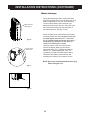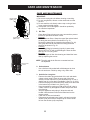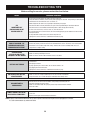
1
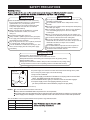
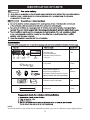
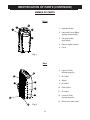
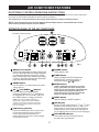
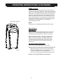
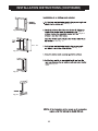
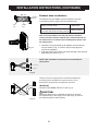
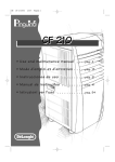
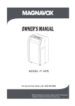
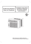
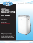
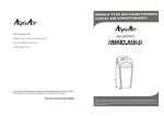
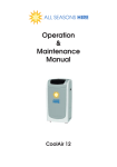
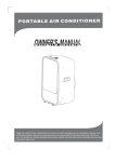
Your Source for Home Comfort
(8,000 & 10,000 BTU)
PORTABLE
AIR CONDITIONER
USER MANUAL
FOR MODELS:
PATC8000
PATC10000
PATCH10000
with 3,400 BTU electric heater
Before using your portable air
conditioner, please read this manual
carefully and keep it for future
reference, along with your receipt.
CONTENTS
SAFETY PRECAUTIONS ..................................................................................... 2
IDENTIFICATION OF PARTS................................................................................3
AIR CONDITIONER FEATURES.......................................................................... 5
OPERATING INSTRUCTIONS .............................................................................6
INSTALLATION INSTRUCTIONS ........................................................................ 8
CARE AND MAINTENANCE ...............................................................................13
TROUBLESHOOTING TIPS ............................................................................... 14
This manual provides the information needed for proper use and maintenance of this air
conditioner. Basic preventative care can help extend the life of this unit. The “Troubleshooting
Tips” section in this manual contains a chart with solutions to the most common problems.
Referring to this section may save time and prevent the need for a service call in the event of
a problem.
NOTE: The rating data indicated on the energy label is based on the testing condition of installing the
un-extended air exhaust duct without flat mouth, round mouth, and wall exhaust adaptors.
(The duct and the adaptors are listed in the accessories chart of this Instruction Manual.)
! CAUTION
● Contact an authorized service technician for repair or maintenance of this unit.
● Contact an installer for installation of this unit if necessary.
● The air conditioner is not intended for use by young children without supervision.
Young children should be supervised to ensure that they do not play with the air conditioner.
● Disabled persons may require assistance with set up.
● If the power cord is to be replaced, replacement work should be performed by authorized
personnel only.
● Installation and repair work must be performed in accordance with the national wiring
standards by authorized personnel only.
● Do not operate your air conditioner in a wet room such as a bathroom or laundry room.
● Units with a heating function should be at least 3 1/3 ft (1 meter) away from any combustible/
flammable materials.
NOTE: All the illustrations in this manual are for explanation purposes only. Unit purchased
may be slightly different.
The design and specifications are subject to change without prior notice for product
improvement. Contact customer service for details.
1
SAFETY PRECAUTIONS
Never do this
! Always do this
Do not operate your air conditioner in a wet room such as a
bathroom or laundry room.
Do not touch the unit with wet or damp hands or when
barefoot.
Do not press the buttons on the control panel with anything
other than your fingers.
Do not remove any fixed covers. Never use this appliance
if it is not working properly or if it has been dropped
or damaged.
Never use the plug to start and stop the unit. (Always use
the switch on the control panel to power the unit on and off.)
Do not cover or obstruct the inlet or outlet grilles.
Do not use hazardous chemicals to clean or come into
contact with the unit. Do not use the unit in the presence of
flammable substances or vapor such as alcohol,
insecticides, petrol, etc.
Do not allow children to operate the unit unsupervised.
Do not use this product for functions other than those
described in this instruction manual.
Your air conditioner should be used in such a way
that it is protected from moisture (i.e. condensation,
splashed water, etc.). Do not place your air
conditioner where it can fall or be pulled into water
or any other liquid. If the unit does ever fall into
water, unplug immediately.
Always transport your air conditioner in a vertical
position and stand on a stable, level surface
during use.
Turn off the product when not in use.
Always contact a qualified person to carry out repairs.
If the supply cord is damaged it must be replaced by
an authorized service technician.
Keep an air path of at least 11.8 in (30 cm) all around
the unit from walls, furniture and curtains.
If the air conditioner is knocked over during use, turn
off the unit and unplug from the main power supply
immediately.
Energy Saving Tips
● Use the unit in the recommended room size.
● Locate the unit where furniture cannot obstruct the air flow.
● Keep blinds/curtains closed during the sunniest part of the day (cooling mode).
● Keep the filters clean.
● Keep doors and windows closed to keep cool air in and warm air out (cooling mode)
or keep warm air in and cool air out (heating mode for units with heat function).
Operation of Current Device
The power supply cord contains a current device that senses damage to the power
cord. To test your power supply cord do the following:
Plug in &
press RESET
TEST
RESET
1. Plug in the air conditioner.
2. The power supply cord will have TWO buttons on the plug head. Press the TEST
button. The RESET button will click as it pops out.
3. Press the RESET button; again you will notice a click as the button engages.
4. The power supply cord is now supplying electricity to the unit.
(On some products this is also indicated by a light on the plug head.)
NOTE: Some plugs have buttons on the top.
NOTES:
Do not use this device to turn the unit on or off.
Always make sure the RESET button is pushed in for correct operation.
The power supply must be replaced if it fails to reset when either the TEST button is pushed or it cannot be reset.
If power supply cord is damaged, it cannot be repaired. Please call customer service to assist with replacement.
The air conditioner must be operated within the temperature range indicated below:
MODE
ROOM TEMPERATURE
COOL
62°F (17°C) – 95°F (35°C)
DRY
55°F (13°C) – 95°F (35°C)
HEAT*
≤86°F (30°C)
*Applies to units with electric heater only.
2
IDENTIFICATION OF PARTS
Vent
Joint
Exhaust
Hose
Flat Mouth
Adaptor
Bolt
Window
Slider Kit
• Exhaust hose
• Flat mouth adaptor
• Window slider kit with bolt
• Vent joint
1 Set
• Foam Seal
1 Piece
• Wall exhaust adaptor A*
Not
• Round mouth adaptor B*
Available
• Expansion Plugs & Wooden Screws*
(*Not included. Set sold separately.)
• Remote Control and Battery
1 Set
• Drain hose
1 Piece
NOTE:
All of the illustrations in this manual are for explanation purposes only. Your air conditioner may be slightly different.
3
IDENTIFICATION OF PARTS (CONTINUED)
NAMES OF PARTS
Front
1
3
4
1. Operation Panel
2
2. Horizontal Louver Blade
(swings automatically)
5
3. Carrying Handle
(both sides)
4. Remote signal receptor
5. Panel
Fig.1
Rear
6. Upper Air Filter
(behind the grille)
9
7. Air Outlet
6
8. Wheel
10
7
9. Air intake
10. Drain Outlet
11
11. Air intake
12
12. Lower Air Filter
(behind the grille)
13
13. Bottom tray drain outlet
8
Fig. 2
4
AIR CONDITIONER FEATURES
ELECTRONIC CONTROL OPERATING INSTRUCTIONS
Before you begin, thoroughly familiarize yourself with the control panel and remote control and all its
functions, then follow the symbol for the functions you desire.
The unit can be controlled by the unit control panel alone or with the remote control.
NOTE: This manual does not include Remote Control Operations, see the Remote Control
Instructions packed with the unit for details.
OPERATION PANEL OF THE AIR CONDITIONER
9
Remote signal receptor
DRY
FAN
COOL
HEAT
MODE
TIMER OFF
ION
TIMER ON
SLEEP
HI
SLEEP
ION
AUTO
MED
SWING
FOLLOW
ME
10
1
2
SPEED
3
4
5
3
6
7
LOW
8
Fig.3
5 POWER button
Power switch on/off.
1 MODE select button
Selects the appropriate operating mode. Each
time you press the button, a mode is selected
in a sequence that goes from AUTO, COOL,
DRY, FAN and HEAT (on models with heating
function). The mode indicator light illuminates
under the different mode setting.
6 TIMER button
Used to initiate the AUTO ON start time
and AUTO OFF stop time program, in
conjuction with the
&
buttons.
2 SWING button
Use this button to initiate/cancel the auto
swing feature .
7 SPEED button
Press to select the fan speed in four stepsAUTO, LOW, MED (on some models) and
HIGH.The fan speed indicator light illuminates
under different fan settings except AUTO
speed. When AUTO fan speed is selected,
all the fan indicator lights turn dark.
3 UP ( ) and DOWN ( ) buttons
Used to adjust (increase/decrease)
temperature settings (2°F/1°C increments)
in a range of 62°F (17°C) to 88°F (30°C) or
the TIMER setting in a range of 0-24 hrs.
8 SLEEP button
Used to initiate the SLEEP operation.
NOTE: The control is capable of displaying
temperature in degrees Fahrenheit or degrees
Celsius. To convert from one to the other, press
and hold the Up and Down buttons at the same
time, for 3 seconds.
9 LED Display
Shows the set temperature in " O C" or " O F" and
the Auto-timer settings. While on DRY and
FAN modes, it shows the room temperature.
(Details about error codes that may appear
on the display can be found on the next page.)
4 ION button (optional)
Press the ION button; the ion generator
is energized and will help to remove
pollen and impurities from the air,
trapping them in the filter. Press it again
to stop the function.
10 FOLLOW ME indicator
To activate the FOLLOW ME feature,
the indicator light flashes.
5
OPERATING INSTRUCTIONS
Error and protection codes:
AUTO operation
- When you set the air conditioner in AUTO mode,
it will automatically select cooling, heating
(on models with heating function only) or fan
only operation.
- The air conditioner will control room temperature
automatically around the temperature point you
have set.
- Under AUTO mode, you cannot select the
fan speed.
E1- Room temperature sensor errorUnplug the unit and plug it back in.
If error repeats, call customer service.
E2- Evaporator temperature sensor errorUnplug the unit and plug it back in.
If error repeats, call customer service.
E4- Display panel communication errorUnplug the unit and plug it back in.
If error repeats, call customer service.
P1- Bottom tray is full - Connect the
drain hose and drain the collected
water away. If error repeats, call
customer service.
TIMER operation
If setting the timer when the unit is on:
First press the TIMER button; the TIMER OFF
indicator light illuminates. It indicates the Auto Stop
program is initiated. Press the TIMER button again;
the TIMER ON indicator light illuminates. It
indicates the Auto Start program is initiated.
NOTE: When more than one error occurs,
the priority of the code display order is:
E4--E2--E1--P1.
COOL operation
- Press the "MODE" button until the "COOL"
indicator light comes on.
- Press the ADJUST buttons "∧" or "∨" to
select your desired room temperature. The
temperature can be set within a range of
62OF-88OF/17OC-30OC.
- Press the "SPEED" button to choose the
fan speed.
If setting the timer when the unit is off:
First press the TIMER button; the TIMER ON
indicator light illuminates. It indicates the Auto Start
program is initiated. Press the TIMER button again;
the TIMER OFF indicator light illuminates. It
indicates the Auto Stop program is initiated.
- Press or hold the UP or DOWN button to change
the Auto time by 0.5 hour increments, up to 10
hours, then at 1 hour increments up to 24 hours.
The control will count down the time remaining
until start.
- The selected time will register in 5 seconds and
the system will automatically revert back to
displaying the previous temperature setting.
- Turning the unit ON or OFF at any time or
adjusting the timer setting to 0.0 will cancel the
Auto Start/Stop timed program.
- When the malfunction (E1 or E2) occurs, the Auto
Start/Stop timed program will also be cancelled.
HEAT operation
(for units with heating function only)
- Press the "MODE" button until the "HEAT"
indicator light comes on.
- Press the ADJUST buttons "∧" or "∨" to
select your desired room temperature. The
temperature can be set within a range of
62OF-88OF/17OC-30OC.
- Press the "SPEED" button to choose the
fan speed. For some models, the fan speed
can not be adjusted under HEAT mode.
- Remove exhaust hose. (See page 11.)
FOLLOW ME
DRY operation
- Press the "MODE" button until the "DRY"
indicator light comes on.
- Under this mode, you cannot select a fan
speed or adjust the temperature.
- Keep windows and doors closed for
dehumidifying effect.
- Remove exhaust hose. (See page 11.)
This feature can be activated from the remote
control ONLY. The remote control serves as a
remote thermostat allowing for the precise
temperature control at its location.
To activate the FOLLOW ME feature, point the
remote control towards the unit and press the
FOLLOW ME button. The light on the unit control
panel will illuminate to indicate it received the signal.
It will continue to send this signal until the feature is
deactivated by pressing the FOLLOW ME button
again. If the unit does not receive the FOLLOW ME
signal during any 7 minute interval, the unit will
beep to indicate the FOLLOW ME mode has ended.
The display on the remote control indicates the
temperature at the remote ONLY.
FAN operation
- Press the "MODE" button until the "FAN"
indicator light comes on.
- Press the "SPEED" button to choose the fan
speed. The temperature cannot be adjusted.
- Remove exhaust hose. (See page 11.)
6
OPERATING INSTRUCTIONS (CONTINUED)
Swings automatically
SLEEP operation
In this mode the selected temperature will increase
(cooling) or decrease (heating - units with heater only)
by 2 O F/1 O C 30 minutes after the mode is selected.The
temperature will then increase (cooling) or decrease
(heating - units with heater only) by another 2 O F/1 O C
after an additional 30 minutes. This new temperature
will be maintained for 7 hours before it returns to the
originally selected temperature. This ends the Sleep
mode and the unit will continue to operate as
originally programmed.
NOTE:
This feature is not available under FAN or DRY mode.
Other features
Auto-Restart
If the unit breaks off unexpectedly due to the power
being cut, it will restart with the previous function
setting automatically when the power is restored.
Wait 3 minutes before resuming operation.
After the unit has stopped, operation cannot be
restarted in the first 3 minutes. This is to protect
the unit. Operation will automatically start after
3 minutes.
Air flow direction adjustment
The louvers can be adjusted automatically .
Fig. 4
Adjust the air flow direction automatically (Fig. 4):
- When the Power is ON, the louver opens fully.
- Press the SWING button on the panel or remote
control to initiate the auto swing feature.
- The louver will swing up and down automatically.
Please do not adjust the louver manually.
7
INSTALLATION INSTRUCTIONS
11.8
.
11
in
8i
n
Fig. 5
Vertical
window
Window Slider Kit
Minimum:2.22 ft (67.5 cm)
Maximum:4.04 ft (123 cm)
Fig. 6
Horizontal
window
7
7
Window Slider Kit
Minimum:2.22 ft (67.5 cm)
Maximum:4.04 ft (123 cm)
bolt
Fig. 7
NOTE: If the window opening is less than 2.22 ft, cut
the extension piece (see Fig. 7a) shorter so the kit
properly fits in the window opening. Only cut if
absolutely necessary. Never cut the hole in the window
slider kit.
Extension
piece
Window slider kit
Fig. 7a
8
INSTALLATION INSTRUCTIONS (CONTINUED)
See Fig. 8.
Fig. 8
sill. See Fig. 9.
See Fig. 10.
26.5” - 48”
Fig. 9
Window sill
See Fig. 11.
Fig. 10
Window sill
Fig. 11
9
INSTALLATION INSTRUCTIONS (CONTINUED)
See Fig. 12.
Fig. 12
height of
height of
sill. See Fig. 13.
26.5” - 48”
See Fig. 14.
Fig. 13
See Fig. 15.
Fig. 14
Fig. 15
10
INSTALLATION INSTRUCTIONS (CONTINUED)
Fig. 16
Flat Mouth
Adaptor
Vent
Joint
Exhaust
Hose
Exhaust hose installation:
The exhaust hose and adaptor must be installed or removed
in accordance with the usage mode as indicated below.
COOL or AUTO mode
Install Hose
FAN, DRY, HEAT*
(*for units with electric heating function)
Remove Hose
Note: Flat mouth adaptor and vent joint must be threaded
counter clockwise onto the exhaust hose. Extend both ends of
the exhaust hose 1-2 inches before installing these pieces onto
the exhaust hose.
Fig. 17
1. Install the vent joint and flat mouth adaptor onto the exhaust
hose as shown in Fig. 16. Refer to the previous pages for
window kit installation.
2. Slide the exhaust hose into the air outlet opening in the direction
depicted by the arrow in Fig. 17.
NOTE: Wall ventilation accessories are not available for
this product.
max 47.25 in (120 cm)
min 11.8 in (30 cm)
Fig. 18
The duct can be compressed or extended moderately
according to the installation requirements, but it is
desirable to keep the duct length to a minimum.
IMPORTANT:
DO NOT OVER BEND THE DUCT. See Fig. 19.
CAUTION:
Fig. 19
Make sure that there is no obstacle around the air outlet of
the exhaust hose (in the range of 20 in (500 mm)) in order for
the exhaust system to work properly.
11
INSTALLATION INSTRUCTIONS (CONTINUED)
Water drainage:
-
During dehumidifying modes, remove the drain
plug from the back of the unit and attach 3/4” vinyl
tube included with the unit (5/8” outer diameter).
For the models without drain connector, just
attach the drain hose to the hole. Place the open
end of the hose directly over the drain area in
your basement floor. See Fig. 20 & 21.
-
When the water level of the bottom tray reaches
a predetermined level, the unit beeps 8 times and
the digital display area shows "P1". At this time
the air conditioning/dehumidification process will
immediately stop. However, the fan motor will
continue to operate (this is normal).
Carefully move the unit to a drain location,
remove the bottom drain plug and let the
water drain away (Fig. ). Restart the machine
until the "P1" symbol disappears. If the “P1”
symbol will not clear after following the above
instructions and waiting a few minutes after
restarting the machine, call customer service.
Remove the
drain plug
Fig.20
Continuous
drain hose
NOTE: Be sure to reinstall the bottom drain plug
before using the unit.
Fig.21
Fig.22
12
CARE AND MAINTENANCE
CARE AND MAINTENANCE
IMPORTANT:
1) Be sure to unplug the unit before cleaning or servicing.
2) Do not use gasoline, thinner or other chemicals to clean
the unit.
3) Do not wash the unit directly under a tap or using a hose.
It may cause electrical danger.
4) If the power cord is damaged, it should be repaired by
an authorized repairman.
Upper filter
(take out)
1. Air filter
Lower filter
(take out)
Fig. 23
-
-
-
Remove the
screws
Fig. 24
Clean the air filter at least once every two weeks to prevent
inferior fan operation because of dust.
Removal
This unit has two filters. Grasp the upper filter tab and take it
out along the arrow direction as shown in Fig. 23.
Remove the lower filter by loosening the screws (Fig. 24);
then grasp the filter tab and take it out along the arrow
direction as shown in Fig. 23.
Cleaning
Wash the air filter by immersing it gently in warm water
(about 104OF/40OC) with a mild detergent. Rinse the filter
and dry it in a cool, dry place.
Mounting
Install the upper air filter after cleaning and install the lower
filter by replacing the screws.
NOTE: The grille and the air filter are connected and can
be separated.
2. Unit enclosure
- Use a lint-free cloth soaked with mild detergent to clean
the unit enclosure. Finish by using a dry, clean cloth.
3. Unit idle for a long time
-
-
Remove the rubber plug at the back of the unit and attach
a hose to drain outlet. Place the open end of the hose
directly over the drain area in your basement floor or over a
shallow pan (if no floor drain is available). (See Fig. 21 & 22.)
Remove the plug from the bottom drain outlet; all of the water
in the bottom tray will drain out. (See Fig. 22.)
Keep the appliance running on FAN mode for half a day in
a warm room to dry the appliance inside and prevent mold
from forming.
Stop the appliance and unplug it. Wrap the cord and
bundle it with the band. Remove the batteries from the
remote control.
Clean the air filter and reinstall it.
Disconnect the exhaust hose. Keep it safe and cover the
window (wall) hole with the adaptor cap or remove slider
kit from the window (wall) completely.
13
TROUBLESHOOTING TIPS
Before calling for service, please review the chart below.
Issue
AIR
CONDITIONER NOT
COOLING ROOM, OR NOT
BLOWING COLD AIR
AIR CONDITIONER COOLING BUT
ROOM IS TOO WARM - ICE
FORMING ON COOLING COIL
BEHIND DECORATIVE FRONT
AIR CONDITIONER
CYCLING ON AND OFF TOO
FREQUENTLY OR NOT ENOUGH
UNIT WILL NOT TURN ON
UNIT BLOWS FUSES OR POPS
CIRCUIT BREAKER
AIR CONDITIONER IS
MAKING NOISES
REMOTE SENSING / FOLLOW ME
DEACTIVATING PREMATURELY
Possible Solutions
• Be sure unit is not too large or too small for the area of the room.
• Verify that all doors, windows, curtains and any other openings are closed off. Verify nothing is obstructing the
airflow to/from the unit and louvers such as curtains, etc.
• Allow enough time for room to cool, especially if outside temp is very high.
• Check that the filter is not dirty and louvers are open all the way and blowing in the direction desired.
• Check that unit is set to Cool Mode and that temperature is down enough (but not too low).
• If unit is near a heat source, such as a stove, etc., then relocate unit.
• If air coming from unit is cool to the touch, then unit is working properly; please double check the first three
bullet points above.
• If using Follow Me remote feature, move remote away from unit.
• Unplug unit for at least 5 minutes. Follow Reset instructions on plug.
• Outdoor temperature is below 64ºF (18ºC). To defrost the coil, set to Fan Only mode.
• Air filter may be dirty. Clean filter. Refer to Care and Maintenance section. To defrost, set to Fan Only mode.
• Thermostat is set too cold for night-time cooling. To defrost the coil, set to Fan Only mode. Then, set
temperature to a higher setting.
• Be sure unit is not too large or too small for the area of the room.
• Make sure nothing is blocking the louvers.
• Make sure there is no dirt or debris inside the unit or on the filters.
• Reset circuit breaker. Make sure there are not too many items (ie lamps, TV’s, etc.) working off the
same breaker.
• Check plug connection.
• If plug is operating on an on/off switch, be sure that the switch is ‘on’.
• Try plugging unit into another outlet.
• Unplug unit for at least 5 minutes. Follow Reset instructions on plug.
• Make sure there are enough available amps on the circuit for the air conditioner.
• Large units which run on a 230v will require a dedicated 20 or 30 amp circuit.
• Check to be sure the unit is free from debris. Verify nothing is obstructing the unit.
• Check the fan blade for cracks or chips.
• Make sure the window slider kit is properly and securely mounted inside the window.
• Clean the air filter.
• Remote control not located within range. Place remote control within 20 ft and 180º radius of the front
of the unit.
• Remote control signal obstructed. Remove obstruction.
NOTE: A highly recommended troubleshoot for any issue in general consists of turning off unit and unplugging for 5 minutes.
It is also recommended to try another wall outlet.
14
Your Source for Home Comfort
Distributed by:
Perfect Aire, LLC
5151 Belt Line Rd.
Suite 878
Dallas, TX 75254
877-365-6274
www.perfectaire.us
Specification and performance data is subject to change without notice.
Printed in PRC