1
FEATURES
n Infrared pass through housing
n Miniature size and shape
Installation friendly design:
n 10' of cable with 3.5mm plug
n Reliable adhesive backing
n Includes IR blocking cover
PACKAGE CONTENTS: IR-E1
n IR-E1 Emitter x 1
PREPARING FOR
INSTALLATION
The IR-E1 and IR-E2 are typically mounted to the
infrared remote receiver windows of audio/video
components, using the attached self-adhesive
tape. The emitter directs its infrared output
toward the component, not out into the room. If
the component has a tray or door that opens, you
may have to route the emitter wire from the top
or the side of the component. Make sure the
mounting surface is cleaned and degreased
before installation.
n 10 Feet of Connecting Wire x 1
n IR Blocking Cover x 1
n IR-E2 Emitter x 1
INCREASING THE WIRE LENGTH
1. Locate the IR remote receiver window of each
component to control. The receiver is usually
located behind its own plastic window, on the
front of the component.
If the connecting wire is too short to reach the IR
Connecting Blocks, an additional length of wire
may be spliced in to extend it. Cut the emitter wire
approximately six inches from the plug end, strip off
1/4", and connect your additional wiring between
the ends of the original emitter wire. For distances
between 10 and 20 feet upgrade the original wire to
an 18 gauge 2-conductor wire. For distances of up
to 200 feet a 16 gauge two-conductor wire should
be used.
2. Make sure the mounting surface is clean.
3. Attach the IR-E1/E2 directly over the IR remote
receiver windows of the components using its
self-adhesive tape.
4. Route the connecting two-conductor wire to
the IR Connecting Block and plug it into an
Emitter output.
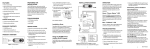
IR-E1/E2
Be sure to observe proper polarity when extending
the emitter wire.
Self-adhesive tape
JobSite
IR-E1/E2
Emitter
Infrared
LED
n Extra emitter adhesive strips x 4
10 feet of
2-conductor
24 gauge
connecting
wire
IR-CB2
Infrared
Transparent
Housing
12V DC
Power Supply
(Not Supplied)
plugged into the
Switched Outlet
IR-SMR
3.5mmmo
no miniplug
Figure 1
2
USING THE IR
BLOCKING COVER
Stereo Receiver
IR Blocking
Cover
n IR Blocking Covers x 2
The wire lead marked with a gray stripe is positive
(+); the unmarked lead is negative (-).
6. On IR Connecting Blocks with selectable
Emitter outputs, make certain the HI-LOW
SWITCH is placed in the LOW position. See
figure 2 and 3.
PRODUCT OVERVIEW
n 10 Feet of connecting wire x 1
1
Figure 2 Connecting the emitter to the main
system unit’s emitter low outputs.
5. Coil any excess wire and tie it in place.
n Extra Emitter Adhesive strips x 2
PACKAGE CONTENTS: IR-E2
INSTALLATION
3
12V DC Power Supply
Plugged into an
Unswitched AC Outlet
Powers the System
4
Figure 3
To prevent A/V components from receiving IR
commands from sources other than the IR-E1 and
IR-E2, the IR Blocking Cover should be used. The IR
Blocking Cover is designed to cover both the IR-E1
and IR-E2 and the IR Receiver window of the
component. The IR Blocking Cover serves two
functions:
1. It ensures that a component receives IR signals
solely from the IR-E1 and IR-E2.
Figure 4 Mounting the IR Blocking Cover.
MOUNTING THE
IR BLOCKING COVER
Make sure the mounting surface is clean before
installing the blocking cover. You may improve
the appearance by trimming the cover with
scissors to exactly cover the remote receiver
window. Mount the blocking cover (using the
self-adhesive tape) so that the IR-E1 and IR-E2
and the IR remote receiver window of the
component are completely covered. See figure 4.
TROUBLESHOOTING
Testing the Remote Control
Test to see that the hand-held remote control
operates the component when you point it at the
front panel (check the batteries if it does not).
IR Connecting Blocks Power Supply
2. It prevents the IR output of the IR-E1 and IR-E2
from radiating to other components or IR
receivers.
Check that the red power light on the IR
Connecting Blocks is lit (the in-line power supply
should be plugged into an active AC wall outlet
and supplying 12V DC).
5
6
Over Please
IR Saturation
Solution
LIMITED WARRANTY
Sometimes the emitter output can saturate the IR
receiving window of a component. When this
occurs, the IR command will not be executed.
This can occur anytime the output level of the
emitters exceeds the input capability of the IR
receiving circuit. Having a Plasma TV in the
system can cause this to occur on an intermittent
basis.
You can eliminate optical feedback by covering
all emitters with the supplied IR Blocking Covers.
There are many methods for reducing
interference. Which solution is best for you
depends on your situation.
JobSite Systems (“JOBSITE”), a Niles Audio
Corporation company, warrants its passive products
(those not requiring AC or battery power) to the
original purchaser to be free of manufacturing
defects in material and workmanship for a period of
ten years from date of purchase.
IR system
Solution
1. Remove the IR Blocking Cover if you
are using one.
2. Turn on the Plasma TV, because this may be
contributing to the problem.
JOBSITE SYSTEMS
12331 S.W. 130 STREET, MIAMI, FLORIDA 33186
P 866.4JB.SITE (866.452.7483) – F 305.238.0185
WWW.JOBSITESYSTEMS.COM
© 2004 JobSite Systems. All rights reserved. JobSite, Pure
Custom and Niles are registered trademarks of Niles Audio
Corporation and the JobSite Logo is a trademark of Niles Audio
Corporation. All other trademarks are the property of their
respective owners. Some JobSite products (or components
thereof) are manufactured under one or more U.S. Patents,
foreign equivalents and/or pending patents (see product for
details). Because we constantly strive to improve our products,
JobSite reserves the right to change product specifications,
descriptions, and prices without notice. The technical and other
specifications of information contained herein are not intended to
set forth all technical and other specifications of JobSite
products. Additional information can be obtained at
WWW.JOBSITESYSTEMS.COM or by calling JobSite at
866.452.7483. Printed in China. 7/04 DS00392BCN
SPECIFICATIONS
3. Relocate the IR Emitter approximately 1/2"
away from the IR Receiving window. Some
experimentation will be required to determine
the best location for emitter.
4. Test system. Do not use an IR Blocking Cover if
a component is sensitive to IR saturation.
Optical Feedback Loop
If you have an IR Receiver in the same room as
an emitter, and you have some low-level noise or
interference, an optical feedback loop can occur
which will interfere with proper operation.
Symptoms can include: poor range, intermittent
operation or no operation.
Works with practically all brands of
IR remote controls
IR transmitting
Up to 4' (line of sight)
Emitters mount directly to the IR window of a
component
Wiring requirements
10" of 2-conductor 24-gauge wire with a 3.5mm
plug is supplied
Use 18-gauge for distances up to 20' and 16gauge for up to 200’
Mounting
Self-adhesive, surface mount
Dimensions
5/16" wide x 3/16" high x 1/2" deep
IR Blocking Cover Dimensions
2" wide x 2" high x 1/4" deep
Warranty: 2 year limited
JOBSITE warrants its passive loudspeaker products
(those not requiring AC or battery power) to the
original purchaser to be free of manufacturing
defects in material and workmanship for a period of
five years from date of purchase.
JOBSITE warrants its indoor/outdoor loudspeaker
products to the original purchaser to be free of
manufacturing defects in material and workmanship
for a period of two years from date of purchase.
JOBSITE warrants its all weather rock loudspeaker
products to the original purchaser to be free of
manufacturing defects in material and workmanship
for a period of five years from date of purchase.
JOBSITE warrants its active products (those
requiring AC or battery power) to the original
purchaser to be free of manufacturing defects in
material and workmanship for a period of two years
from date of purchase.
This Warranty is subject to the following additional
conditions and limitations. The Warranty is void and
inapplicable if JOBSITE deems that the product has
been used or handled other than in accordance with
the instructions provided by the manufacturer,
including, but not limited to, damage caused by
accident, mishandling, improper installation, abuse,
negligence, or normal wear and tear, or any defect
caused by repair to the product other than by
JOBSITE or an authorized JOBSITE wholesale
distributor.
To obtain warranty service, you must write to
9
10
11
JOBSITE: Include your name, address, telephone
number, model number and serial number of your
unit, and a brief description of the problem.
INSTALLATION & USER GUIDE
A factory Return Authorization Number will be sent
to you. DO NOT RETURN ANY UNIT WITHOUT FIRST
RECEIVING WRITTEN AUTHORIZATION AND
SHIPPING INSTRUCTIONS FROM JOBSITE.
If the above conditions are met, the purchaser’s sole
remedy shall be to return the product to JOBSITE, in
which case JOBSITE will repair or replace, at its sole
option, the defective product without charge for
parts or labor. JOBSITE will return the unit repaired
or replaced under warranty by shipping it by its usual
shipping method from the factory (only) at its
expense within the United States of America. THERE
ARE NO OTHER WARRANTIES, INCLUDING,
WITHOUT LIMITATION, EITHER EXPRESS OR
IMPLIED WARRANTIES OF MERCHANTABILITY OR
FITNESS FOR A PARTICULAR PURPOSE, WITH
RESPECT TO THE PRODUCT.
For Transmitting
Infrared Commands to
Audio/Video Components
REPAIR OR REPLACEMENT AS PROVIDED UNDER
THIS WARRANTY IS THE EXCLUSIVE REMEDY OF
THE CONSUMER/PURCHASER. NILES SHALL NOT
BE RESPONSIBLE FOR ANY INCIDENTAL OR
CONSEQUENTIAL DAMAGES EXCEPT TO THE
EXTENT PROVIDED (OR PROHIBITED) BY
APPLICABLE LAW.
Some states do not allow the exclusion or limitation
of incidental or consequential damages, so the
above limitation may not apply to you. This warranty
gives you specific legal rights, and you may also
have other rights, which vary from state to state.
For the name of the nearest authorized JOBSITE
wholesale distributor, contact:
JobSite Systems
12331 S.W. 130 Street, Miami, Florida 33186
WWW.JOBSITESYSTEMS.COM
12
SINGLE/DUAL IR EMITTER
IR-E1/E2