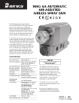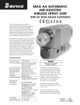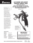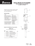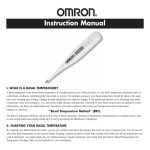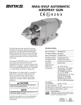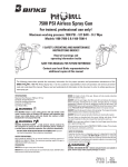
1
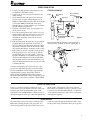
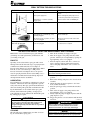
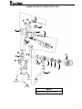
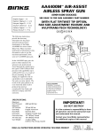
AA4000 AIR-ASSISTED
AIRLESS SPRAY GUN
II 2 G X
The following instructions provide the
necessary information for the proper
operation and preventive maintenance
of the Binks AA4000 Air-Assisted
Airless Spray Gun. Please read and
understand all information in this
document in order to get the maximum
performance from your new AA4000
spray gun.
In the AA4000 spray gun, the paint or
other material to be sprayed is preatomized and forced through the carbide tip
by the typical 1,500-3,800 psi fluid
pressure (with capabilities up to 4,000
psi/275 bar). As a result of the preatomizing, the final shaping air supplied by
the air cap produces an exceptionally
fine and even spray pattern. The result
of this spray pattern is an even finish
that lends itself to products that need an
exceptionally fine finish with reduced
overspray and VOC emissions.
SPECIFICATIONS:
Maximum
Fluid Pressure:
Maximum
Air Pressure:
Gun Body:
Fluid Path:
Fluid
Shut Off Type:
4000 psi/275 bar
100 psi/6.8 bar
Forged Aluminum
Stainless Steel
Tungsten Carbide Seat standard
(UHMW Seat optional)
Fluid Inlet Size: 1/4" NPS(m) Thread
Air Inlet Size:
1/8" NPT(m) x 1/4" NPS(m)
D.M. Nipple
Gun Weight:
16-oz.
Product shown is covered by U.S. patent No. 6,276,616.
Foreign patents are issued or pending.
Replaces
Part Sheet
77-2776R-8
Part
Sheet
77-2776R-9
!
WARNING
HIGH PRESSURE CAN CAUSE SERIOUS INJURY
IF EQUIPMENT IS INSTALLED OR USED INCORRECTLY—
READ, UNDERSTAND, AND OBSERVE
ALL WARNINGS AND INSTRUCTIONS
IN THIS MANUAL.
FLAMMABLE, EXPLOSIVE AND TOXIC VAPORS
HIGH PRESSURE SPRAY
AND HOSE LEAKS
OPERATE EQUIPMENT ONLY AFTER ALL
INSTRUCTIONS ARE CLEARLY UNDERSTOOD.
In this part sheet, the words WARNING, CAUTION and NOTE are used to emphasize important safety information as follows:
WARNING
!
!
Hazards or unsafe practices which could
result in severe personal injury, death or
substantial property damage.
CAUTION
Hazards or unsafe practices which could
result in minor personal injury, product
or property damage.
INJECTION HAZARD
Spray from the gun, hose leaks, or ruptured components can inject fluid into
your body and cause extremely serious injury, including poisoning or the need
for amputation. Splashing fluid in eyes or on skin can also cause a serious injury.
• Fluid injected into the skin might look like just a cut, but is a serious injury and
should be treated as such. GET IMMEDIATE MEDICAL ATTENTION. INFORM THE
PHYSICIAN WHAT TYPE OF MATERIAL WAS INJECTED.
• Do not point the spray gun at anyone or any part of the body.
• Do not put fingers or hand over the spray tip.
• Do not stop or detect fluid leaks with a rag, hand, body or glove.
• Do not use a rag to blow back fluid. THIS IS NOT AN AIR SPRAY GUN.
• Engage the gun safety when not spraying.
• ALWAYS RELIEVE THE PRESSURE WHENEVER WORKING ON THE SPRAY GUN.
• Tighten all fluid connections before operating equipment.
• Check all hoses, tubes, and couplings daily. Replace all worn, damaged, or
loose parts immediately.
Hazardous fluids or toxic fumes can cause serious injury or death if splashed on
skin or in the eyes, swallowed or inhaled.
TOXIC FLUID HAZARD
• Know the specific hazards of the fluid you are using. This information is on the
MSDS for the material being used. Read all fluid manufacturer’s warnings.
• Store hazardous fluids in approved containers only. Dispose of all hazardous
fluids in accordance with all state, local and national guidelines.
• Wear the appropriate protective clothing, gloves, eyewear and respirator.
Equipment misuse can cause the equipment to fail, malfunction, or start unexpectedly and result in serious injury.
NOTE
Important installation, operation or
maintenance information.
• Use the equipment only for its intended purpose. If you are unsure about its
purpose call your local Binks distributor.
• Do not alter or modify this equipment. Use only genuine Binks parts.
• Do not exceed the maximum working pressure of the lowest rated system
component. THE MAXIMUM RATING OF THE AA4000 IS 4000 PSI (275 BAR)
FLUID PRESSURE. DO NOT EXCEED THE FLUID PRESSURE RATING.
• Route all hoses away from all sharp edges, moving parts, hot surfaces and
high traffic areas.
• Do not use hoses to pull the equipment.
• Use only Binks approved hoses. Do not remove spring guards from hoses,
these are on the hoses to prevent rupture from kinking at the connectors.
• Use only solvents compatible with hoses and wetted parts of the equipment
used.
• Comply with all applicable local state and national fire, electrical, and other
safety regulations.
Improper grounding, poor air ventilation, open flames, or sparks can cause a
hazardous condition and result in fire or explosion and cause serious injury.
FIRE AND EXPLOSION HAZARD
• Ground the equipment and object being sprayed.
• Provide fresh air ventilation to avoid the build up of flammable fumes from
the material being sprayed or from solvent.
• Extinguish all open flames or pilot lights in spray area.
• Electrically disconnect all equipment in the spray area.
• Keep the spray area free from all debris, including solvent rags.
• If there is any static sparking while using the equipment, STOP SPRAYING
IMMEDIATELY. Identify and correct problem.
NOISE LEVELS
EQUIPMENT MISUSE HAZARD
• This equipment is for professional use only.
• Read and understand all instructional manuals, tags, and labels before operating equipment.
• The A-weighted sound level of spray guns may exceed 85 dB(A) depending
on the setup being used. It is recommended that ear protection is worn at all
times when spraying.
The Spray Gun models listed in the following declaration of conformity may be used in some potentially explosive atmospheres ONLY when
the special conditions for safe installation and operation have been followed as expressed in this user manual (Part Sheet). These models
are approved to ATEX regulations 94/9/EC, protection level: II 2 G X: Suitable for use in Zones 1 and 2.
EC Declaration of Conformity
Manuf. By:
Industrial Finishing
195 Internationale Blvd.
Glendale Heights, IL 60139
Type/Series:
Manifold Mounted Automatic Spray Guns
Model:
AA1500, AA4000
The equipment to which this document relates is in conformance with the following standards or other normative references:
EN ISO 12100-1&2:2003 and BS EN 1953:1999 and thereby conform to the protection requirements of Council Directive
98/37/EC relating to Machinery Safety Directive, and;
EN 13463-1:2001, Council Directive 94/9/EC relating to Equipment and Protective Systems for use in Potentially Explosive
Atmospheres, protection level II 2 G X.
Approved By:
______________________________
Chuck McCulloch,
2
11/19/07
Date: ____________
Industrial Finishing
Industrial Finishing reserves the right to modify equipment specification without prior notice.
SPRAY GUN SET-UP
1. Connect your high-pressure airless fluid hose to the
gun fluid inlet and tighten securely.
2. Connect your air hose to the gun air connection and
tighten securely.
3. Set the fluid pressure at the gun’s lower end of the
pressure range. A typical starting fluid pressure is
1600 psi. Actual starting pressure points may be higher
or lower than 1600 psi and depend on the setup—
including the type of pump used, the type of material
sprayed, and the spray gun itself.
4. Using the control knob on the gun air regulator, set
the air pressure at zero.
5. To test the spraying pattern, spray a piece of wood or
cardboard with a fast pass about one foot away from
the piece. The results of the test will allow you to
determine the uniformity of the particle size and
spraying pattern.
6. If the spraying pattern develops tails or is not uniform,
gradually increase the air pressure as necessary to
develop a uniform spraying pattern. Typically, 10 psi
air pressure is adequate, since the air is used to shape
the patterns rather than for atomization of the coating.
7. If the quality of spray is acceptable, begin spraying.
If the spraying rate is too slow to keep up with the
production line speed, or if the quantity of material
sprayed is inadequate for acceptable coverage, gradually increase the fluid pressure in 50 psi increments
using the fluid regulator control knob. However, note
that as the fluid pressure increases, more air is needed
to eliminate the tails.
TYPICAL HOOK-UP
Grounding
Wire
Regulator
Pump
Oil and Water
Extractor
Air
In
Air
Regulator
Air
Gun
Air
Fluid Filter
Fluid
Figure 1
Fan pattern adjustment: turn knob counterclockwise to
increase pattern; clockwise to decrease pattern (Fig. 2).
Fan Control
Knob
Consistency in spraying can be increased across spray
gun operators and similar spraying jobs by developing
pressure standardization charts. Repeat step 6 until the
required material coverage and spraying speed are
achieved. If the maximum fluid pressure is reached
before the required material coverage and spraying speed
are achieved, you may need to switch to a larger fluid tip.
Figure 2
FLUID TIP SELECTION
Factors to consider in selecting a fluid tip for an airassisted airless spray gun include (1) the size of the parts
being sprayed; (2) the production line speed; (3) the
material flow rate and film thickness; (4) the viscosity of
the material applied; (5) the type of material applied; and
(6) the quality of atomization of the coating required.
The selection of a fluid tip necessary to perform a specific spraying job is best determined through a combination
of experimentation and expert advice from your material
and equipment suppliers.
FLUID HOSES
Air-assisted airless spray guns operate at fluid pressures
higher than operating pressures of air spray guns. As a
result, when operating an air-assisted airless spray gun, it
is critical to select the appropriate fluid hose that is rated
for the pressure range at which the airless gun is operated.
3
TROUBLESHOOTING DEFECTIVE SPRAY PATTERNS
The following procedure summarizes the steps that an
operator must immediately take when the first signs of a
defective spray pattern emerge.
1. Check the external portion of the fluid tip for material
buildup. If buildup has occurred, secure the gun trigger safety switch and clean the gun fluid tip with a
non-metal soft brush.
2. If the spray pattern exhibits signs of tails at the top or
bottom ends of the pattern, increase the air pressure
gradually until the tails disappear.
3. If increasing air pressure does not dissipate the tails,
the fluid tip may be worn and may need to be
replaced. Another sign of the need to replace a worn
tip is a gradual decline in spraying pattern width.
4. If cleaning or replacing the fluid tip does not dissipate
the tails; the spraying defect is most likely due to the
material temperature and/or viscosity.
5. If pattern pulsation or blinking occurs, check the pressure regulators, all downstream regulators, and the
pump. These may require further adjustment or even
repairs.
Distorted
Pattern
Tails
Correct
Pattern
Hour
Glass
Figure 3
GENERAL TROUBLESHOOTING
PROBLEM
CAUSE
ACTION
Fluid leaking from the back
of seal cartridge assembly (8)
Worn seal or needle shaft.
Replace needle packing cartridge (8).
Fluid leaking from the front
of the gun
Needle ball worn or damaged.
Replace needle packing cartridge (8).
Worn seat assembly.
Replace fluid seat (4).
Spray tip seal leaking.
Fluid in air passages
Leaking around fluid seat.
Tighten retaining ring (1)
Replace carbide tip assembly (3).
Tighten or replace fluid seat (4).
Slow fluid shut off
Fluid buildup on cartridge assembly.
Clean or replace cartridge assembly (8).
No fluid output when triggered
Tip orifice plugged.
Turn off fluid supply. Relieve pressure into a
closed-grounded container.
Engage trigger safety.
Remove tip guard assembly (1) and air cap (2)
and the carbide tip (3).
Clean or replace carbide tip assembly (3).
Turn off fluid supply. Relieve pressure into a
closed-grounded container.
Remove trigger (20). Remove needle packing
cartridge (8). Loosen collet and move until
the needle is flush with the rear of the collet.
Tighten collet.
Turn off fluid supply. Relieve pressure into a
closed-grounded container. Turn off air supply
to pump and relieve fluid pressure with bypass
valve. Engage trigger safety. Very slowly loosen
the hose connection at the gun to relieve any
pressure in hose. Remove hose and clear
obstruction.
Collet on needle has slipped.
Fluid filter or fluid hose plugged.
IMPORTANT REGULATORY NOTE
The AA-4000 Air-Assisted H.V.L.P. hand spray gun combines the proven efficiency of the Binks compliant spray guns with
air-assisted atomization to yield a reliable, carefully engineered compliant spray gun. With 25' of 5/16" I.D. air hose and
regulator set at only 20 p.s.i. the compliant air cap registers 10 p.s.i. of atomization air to shape and soften the spray
pattern. The AA-4000 air-assisted H.V.L.P. gun operates at high transfer efficiencies and fully complies with all government regulations for H.V.L.P. spray guns.
Max. Fluid Input:
Max. static air pressure at regulator with 25' of hose to inlet:
Max. Dynamic Gun Inlet Air Pressure:
Gun Body:
Fluid Path:
4
4000 p.s.i.
20 p.s.i.
15 p.s.i.
Forged Aluminum Alloy
Stainless Steel and Tungsten Carbide
SPRAY PATTERN TROUBLESHOOTING
PROBLEM
CAUSE
ACTION
Fluttering Spray Pattern
Insufficient fluid supply.
Adjust fluid regulator or fill fluid supply
tanks.
Air in paint supply line.
Check and tighten pump siphon hose
connections, bleed air from paint line.
Attempting to “feather” (Partially
trigger gun).
Cannot feather with an AA4000 gun.
Striping Spray – Fingers
Carbide tip partially plugged.
Clean or replace carbide tip assembly.
Irregular Pattern
Fluid builds up on carbide tip, or tip
partially plugged.
Clean carbide tip.
On defective side of pattern, air horn
holes are plugged.
Clean air horn holes with solvent and
a soft brush.
On defective side of pattern, air horn
holes are plugged.
Clean air horn holes with solvent and
a soft brush or toothpick.
Pattern pushed to one side, same
side of air cap gets dirty
AIR-ASSISTED AIRLESS SPRAY GUN MAINTENANCE AND CLEANING
Maintenance of air-assisted airless spray guns includes
(1) fluid tip wear and replacement; (2) lubrication; and
(3) cleaning of the gun.
FLUID TIP
Operating an air-assisted airless spray gun with a worn
fluid tip will result in increased usage of spraying material and therefore, HAP emissions. For example, an
increase in the diameter of a tip from 0.015 inch to 0.021
inch due to wear can result in up to a 100 percent
increase in material consumption and cost. To prevent
waste in spraying material and non-value-adding costs, a
maintenance schedule that includes fluid tip inspection
and replacement must be established.
LUBRICATION
Proper lubrication is essential for optimum spray gun performance. Lubrication allows the equipment to operate
easily and correctly. The spray gun should be lubricated
after each cleaning. The points that need lubrication during the maintenance of air-assisted airless spray guns
include (1) the fluid needle packing; (2) trigger pivot
point. Gun lube is used to lubricate the fluid needle packing and trigger pivot point.
!
CAUTION
Never immerse the entire gun in solvent or thinners. Some
gun parts will lose their lubricative film and wear more
quickly. Additionally, solvents may carry impurities
throughout the gun body and allow them to clog small air
and fluid passages.
CLEANING
The following steps summarize the procedure for cleaning air-assisted airless spray guns:
1. Turn off the atomizing air supply to the gun.
2. Turn off air supply to the pump and relieve fluid
pressure. This may be accomplished by opening the
bypass/priming valve, if so equipped.
3. Place the siphon (suction) tube into a solvent container. If pump is directly immersed in material,
remove the pump and immerse it in a solvent container.
NOTE
Use only compatible solvents that are identified as
approved for cleaning and wash-off use.
4. Place the gun trigger safety switch in the locked
position.
5. Remove the fluid tip and place it in a closed solvent
container.
6. Adjust the pump air supply regulator to its lowest
level (counter-clockwise).
7. Place the gun trigger safety switch in the unlocked
position.
8. Turn on the air supply to the pump and close the
bypass/priming valve, if so equipped.
9. Slowly adjust the pump air supply regulator until the
pump begins to cycle.
10. Trigger the gun into a closed container until the fluid
(continued)
runs clear.
!
WARNING
Failure to reduce pump air supply pressure or to use a
closed container can result in material “bounce-back”.
Material “bounce back” can cause injury and damage.
NOTE
During cleaning, the gun may only be sprayed into a closed
container, never flush the gun into the air or spray booth.
5
CLEANING (Continued)
11. Using a rag dampened with solvent, wipe the exterior surface of the gun. Additionally, some solvents are
prohibited from being used for cleaning. The operator must take care to use only approved cleaning solvents for equipment cleaning. These materials are
clearly labeled as approved for cleaning and wash off
operations. If the operator has any question on
selecting appropriate cleaning solvents, the operator
should consult a supervisor or plant environmental
staff.
WIRE AND BALL ASSEMBLY AND SEAT REPLACEMENT
Refer to assembly drawing on page 7 to locate numbered
items.
1. Engage the trigger safety.
2. Shut off fluid pump and disconnect its air or power
supply.
3. Release pressure from the entire fluid system, from
the pump to the spray gun.
4. Remove tip guard assembly (1), air cap (2) and spray
tip (3). Remove trigger (20) by removing the trigger
stud (13) and the trigger screw (12).
5. Remove the AA4000 needle packing cartridge (8).
6. Carefully install new AA4000 needle packing
cartridge (8).
7. Remove fluid seat (4) and o-ring.
8. Install new fluid seat (4) and o-ring.
9. Reinstall trigger (20), trigger stud (13) and trigger
screw (12).
10. Reinstall air cap (2), spray tip (3) and tip guard
assembly (1).
AIR VALVE REPLACEMENT
1. Engage the trigger safety.
2. Shut off fluid pump and disconnect its air or power
supply.
3. Release pressure from the entire fluid system, from
the pump to the spray gun.
4. Remove trigger (20) by removing the trigger stud
(13) and the trigger screw (12).
5. Remove air valve assembly (21).
6. Replace air valve assembly (21).
7. Reinstall trigger (20), trigger stud (13) and trigger
screw (12).
PARTS LIST
When ordering, please specify Part No.
(Not all part numbers are available for purchasing.)
ITEM PART
NO.
NO.
1
54-4983
2
54-4978 ◆
54-4980
3
113-0XXXX
DESCRIPTION
QTY.
TIP GUARD ASSEMBLY .............. 1
AA4 AIR CAP (Standard) .............. 1
AA2 AIR CAP (Optional) ................ 1
CARBIDE TIP ASSEMBLY ............ 1
(See Tip Selection Chart, pg. 8)
4
4A
5
6
7
8
54-4960*
20-6037 ■
54-4906
54-4986
54-4923*
54-4963*
FLUID SEAT
(Tungsten Carbide ........
Standard or UHMW Optional, 54-4926)
1
O-RING........................................
FLUID TUBE ASSEMBLY..............
GUN HEAD ................................
FRONT HEAD GASKET ..............
NEEDLE PACKING CARTRIDGE....
1
1
1
1
1
(4,000 PSI Maximum)
9
10
11
12
6
—
54-4925
54-4977
54-4939
GUN BODY (Not Sold Separately)
FLUID INLET NUT........................ 1
FAN CONTROL ASSEMBLY ........ 1
TRIGGER SCREW ........................ 1
ITEM
NO.
PART
NO.
DESCRIPTION
QTY.
13
14
15
16
17
54-4938
—
54-4947
54-4943
54-4975▲
TRIGGER STUD ..........................
FLAT PLUG (Not Sold Separately)
FLUID TUBE BRACKET SPACER ..
FLUID TUBE BRACKET................
PUSH IN TUBE FITTING ..............
1
18
19
20
21
22
20-6718
54-4944●
54-4937
54-4909*
71-28
BUTTON HEAD CAP SCREW ......
FLUID INLET FITTING..................
TRIGGER......................................
AIR VALVE ASSEMBLY................
D.M. NIPPLE................................
23
54-4725
FILTER ASSEMBLY (100 Mesh) ........ 1
1
1
1
1/8" NPT(m) x 3/8" O.D.
1
1
1
1
1
1/8" NPT(m) x 1/4" NPS(m)
◆ Also available: 20-6750-K10 (Kit of 10 O-rings for AA-4 Air Cap).
* Available as part of Repair Kit 54-4993.
■ Also available: 20-6037-K10 (Kit of 10 O-rings).
▲ Alternate Push-In Tube Fitting (17) is included in gun package.
● Alternate Fluid Inlet Fitting (19)—order separately.
AA4000 AIR-ASSISTED AIRLESS SPRAY GUN
13
12
11
10
14
9
8
21
15
20
1
16
22
7
6
4A
4
3
2
5
18
23
17
See
note
below
(Alternate)
19
(Alternate)
NOTE
Do not overtighten for ease of filter replacement.
Adequate torque required is 5 – 6 ft. lbs.
7
SPRAY TIP SELECTION CHARTS
HOW TO ORDER THE AA 4000 AIRASSISTED AIRLESS SPRAY GUN
PART NO.
SIZE
FAN
WIDTH
PART NO.
SIZE
FAN
WIDTH
4000-0000-4
113-01110
113-01112
113-01114
.011
.011
.011
8"-10"
10"-12"
12"-14"
113-01806
113-01808
.018
.018
4"-6"
6"-8"
113-01304
113-01306
113-01308
113-01310
113-01312
113-01314
113-01316
.013
.013
.013
.013
.013
.013
.013
2"-4"
4"-6"
6"-8"
8"-10"
10"-12"
12"-14"
14"-16"
113-01906
113-01908
113-01910
113-01912
113-01914
113-01916
113-01918
.019
.019
.019
.019
.019
.019
.019
4"-6"
6"-8"
8"-10"
10"-12"
12"-14"
14"-16"
16"-18"
113-01506
113-01508
113-01510
113-01512
113-01514
113-01516
113-01518
.015
.015
.015
.015
.015
.015
.015
4"-6"
6"-8"
8"-10"
10"-12"
12"-14"
14"-16"
16"-18"
113-02110
113-02112
113-02114
113-02116
113-02118
.021
.021
.021
.021
.021
8"-10"
10"-12"
12"-14"
14"-16"
16"-18"
113-01706
113-01708
113-01710
113-01712
113-01714
113-01716
113-01718
.017
.017
.017
.017
.017
.017
.017
4"-6"
6"-8"
8"-10"
10"-12"
12"-14"
14"-16"
16"-18"
113-02410
113-02412
113-02414
113-02416
113-02418
.024
.024
.024
.024
.024
8"-10"
10"-12"
12"-14"
14"-16"
16"-18"
113-02710
113-02712
113-02714
113-02716
113-02718
.027
.027
.027
.027
.027
8"-10"
10"-12"
12"-14"
14"-16"
16"-18"
(Standard AA4 Air Cap less Spray Tip)
(Optional AA2 Air Cap order separately)
Spray Tip must be ordered separately.
Use this chart to determine orifice size and
fan size required*.
*Note: Listed Fan Widths based on 1000 PSI with
water. Actual results may vary, depending on
material viscosity.
PART NO.
SIZE
FAN
WIDTH
113-00702
113-00704
113-00706
113-00708
.007
.007
.007
.007
1"-2"
2"-4"
4"-6"
6"-8"
113-00902
113-00904
113-00906
113-00908
113-00910
113-00912
.009
.009
.009
.009
.009
.009
1"-2"
2"-4"
4"-6"
6"-8"
8"-10"
10"-12"
113-01104
113-01106
113-01108
.011
.011
.011
2"-4"
4"-6"
6"-8"
FLUID SEAT APPLICATION CHART
APPLICATION CHART
APPLICATION CHART
Carbide (Standard) .....54-4960
UHMW (Optional) ....54-4926
ACCESSORIES
HOSES
71-4990
71-4991
71-8087
71-8088
AIR CAP APPLICATION CHART
AA2 (Optional) 54-4980 Thin to Medium Materials
AA4 (Standard) 54-4978 Medium to Hvy. Materials
ACCESSORIES (Cont.)
15' Polyurethane Air Tubing ASM w/fittings,
3/8" O.D., 1/4" I.D.
25' Polyurethane Air Tubing ASM w/fittings,
3/8" O.D., 1/4" I.D.
15' 3/16" High Pressure Fluid Hose Assembly
25' 3/16" High Pressure Fluid Hose Assembly
FITTINGS
54-4975 1/8" NPT Male x 3/8" O.D. Push-In
Tube Fitting (optional)
54-4976 1/4" NPT Female x 3/8" O.D. Push-In
Tube Fitting (optional)
FLUID FILTERS
103-1241 100 Mesh Inline Filter, 4000 PSI working pressure
54-3655 100 Mesh (Element) Gun Mounted Filter, 5800 PSI w.p.
54-5010 100 Mesh (Screen) Gun Mounted Filter, 4000 PSI w.p.
54-4725 100 Mesh (Element) Gun Mounted Filter, 4000 PSI w.p.
FLUID REGULATORS
845011
Less Gauge, 1000 to 3000 PSI regulated range
845013
Less Gauge, 2000 to 5000 PSI regulated range
CLEANING KIT
54-4994 Cleaning Kit: Includes one standard stiff
nylon pipe cleaning brush, full-size nylon
brush, tip cleaner and Binks Gunners Mate
lubricant.
REPAIR KIT
54-4993 Replacement Parts Kit Items
(Includes Items 4, 4A, 7, 8, 10 and 21)
TEST GAUGES
54-4997 H.V.L.P. Test Gauge AA2
54-5022 H.V.L.P. Test Gauge AA4
REPLACEMENT FILTERS
54-1835 Replacement filters for 54-3655 and 54-4725
54-5012-K10 Replacement filter for 54-5010
Industrial Finishing
Binks has authorized distributors throughout the world. For technical
assistance or the distributor nearest you, see listing below.
Binks Worldwide Sales and Service Listing:
www.binks.com
U.S./Canada Technical Service Office:
195 Internationale Blvd., Glendale Heights, IL 60139
Toll-Free Telephone: 1-888-992-4657 (U.S.A. and Canada only)
Toll-Free Fax: 1-888-246-5732
WARRANTY
This product is covered by Binks’ 1 Year Limited Warranty.
77-2776R-9 Revisions: (P2) Replaced warnings.
12/07 © 2007
Inc. All rights reserved. Printed in U.S.A.