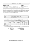
1
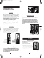
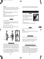
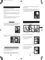
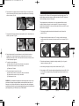
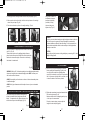
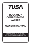
TOKYO
LOS ANGELES
SYDNEY
AMSTERDAM
T.E.C. [TABATA EUROPE CORPORATION] B.V.
Den Brielstraat 2b, 1055RV, Amsterdam, The Netherlands
TEL 020-58-11-280/FAX 020-58-11-285 (Country Code=31)
TABATA U.S.A. INC.
2380 Mira Mar Ave., Long Beach, CA 90815, U.S.A.
TEL 562-498-3708/FAX 562-498-1390 (Country Code=1)
TABATA AUSTRALIA PTY. LTD.
4D James Ruse Business Park 6 Boundary Road, Northmead, Sydney, NSW 2152, Australia
TEL 02-9890-4555/FAX 02-9890-5222 (Country Code=61)
TABATA CO., LTD. JAPAN
1-3-17, Higashikomagata, Sumida-ku, Tokyo, Japan 130-0005
TEL 03-3624-2816/FAX 03-3623-9902 (Country Code=81)
TABATA MFG. [TAIWAN] CO., LTD.
54-8 Hsutsogang, Nankang Vil., Tayuan Hsiang, Tao Yuan Hsien, Taiwan R.O.C.
TEL 03-386-5100/FAX 03-386-5103 (Country Code=886)
© Copyright TABATA CO., LTD
Printed in Taiwan
9 th.
250
0426 EN
EN 1809
BCJ(CE)002-021 GB 10.11.17 9:34 AM ページ 2
CONGRATULATIONS! You are now the owner of one of the many fine TUSA
products. Your new Buoyancy Compensation Jacket is built to exacting standards,
using only the highest quality materials.
Before you use your new B.C.J., please read this manual carefully. The following
warning, cautions, and notes were written to make it possible for you to enjoy your
diving experience with maximum safety.
We at TUSA want you to have many years of dependable service from your new
equipment and have many memorable and safe dives.
Thank you for purchasing one of our high quality products.
WARNING : THIS PRODUCT IS A SCUBA DIVING BUOYANCY DEVICE. THIS IS
NOT A LIFEJACKET: IT DOES NOT GUARANTEE A HEAD UP POSITION OF THE
WEARER AT THE SURFACE.
IMPORTANT NOTICE : TUSA BCJ is intended to be used down to a 50 meter (164
feet) maximum water depth and can be used in cold water with temperature below
10°C.
“MARKING”
When fully inflated in fresh water at sea-level, approximate buoyancy capacity of each
size is as follows:
Size
XS
XS-S
S
M
L
L-XL
XL
Size
XS
XS-S
S
M
L
L-XL
XL
Lift Capacity
BCJ-5960
BCJ-5560 BCJ-2100/3200 BCJ-1800
BCJ-9300
BCJ-3860
–
–
190N (=19.4kgf) 130N (=13.3kgf)
–
–
190N (=19.4kgf) 160N (=16.3kgf)
–
–
190N (=19.4kgf) 230N (=23.5kgf)
–
–
85N (=8.7kgf)
–
105N (=10.7kgf)
125N (=12.8kgf)
140N (=14.3kgf)
–
–
15
BCJ-7000
80N (=8.2kgf) 75N (=7.7kgf)
–
–
–
165N (=16.8kgf)
100N (=10.2kgf)
93N (=9.5kgf)
–
140N (=14.3kgf) 110N (=11.2kgf) 165N (=16.8kgf)
170N (=17.3kgf) 147N (=15.0kgf) 220N (=22.4kgf)
–
–
–
–
205N (=20.9kgf)
220N (=22.4kgf)
Lift Capacity
BCJ-1650
105N (=10.7kgf) 80N (=8.2kgf)
–
–
125N (=12.8kgf) 95N (=9.7kgf)
155N (=15.8kgf) 135N (=13.8kgf)
–
–
195N (=19.9kgf) 170N (=17.3kgf)
–
–
BCJ-6900
140N (=14.3kgf)
–
140N (=14.3kgf)
140N (=14.3kgf)
140N (=14.3kgf)
–
180N (=18.4kgf)
MAX. CAPACITY : 15 Litres Tank
Diameter MAX. : 204mm (8.0 inch)
2
BCJ-6910
140N (=14.3kgf)
–
140N (=14.3kgf)
140N (=14.3kgf)
140N (=14.3kgf)
–
–
NOTICE: The PPE (Personal Protective Equipment) mentioned in this User’s Manual
was submitted to tests for validation of the design and certified according to Art. 10 of
Directive 89/686/EEC by ITALCERT - Viale Sarca 336, 20126 Milano ITALY, Notified
body n° 0426. This device is in compliance with EN 1809:1997 (PPE belonging to
category II) and EN 250:2000 (PPE belonging to category III).
The CE marking means the compliance of the device to the Basic Health and Safety
Requirements of Annex II of Directive 89/686/EEC. The number 0426 near the CE
identifies the Notified Body ITALCERT, entitled for the EC quality control system for
the final product according to Art. 11.A of Directive 89/686/EEC."
The definition of SCUBA according to EN 250:
- demand regulator, - air cylinder with cylinder valves
- carrying harness / support for air cylinder (your B.C.J.!)
- safety device/s (e.g. your Pressure gauge) , - facepiece / mouthpiece
This device is a component of your SCUBA. Remember that a SCUBA must be
composed only of CE marked components. Please read carefully the User’s Manuals
attached to all the components you intend to use to assemble your SCUBA."
Tabata cannot be considered responsible for any damage / injury to persons or things
for eventual uncompatibilities / misuse due to use of non CE marked components.
WARNING STATEMENTS
This information has been put together for your safety. Please read and understand
this manual completely before using your new B.C.J.
Prior to using this product, it is required that you receive training in buoyancy
compensation from an internationally recognized educational organization.
You should also carefully read the owner’s manual and all instructions that
accompany this product before its use.
Misuse of this product may result in uncontrolled ascents, descents, loss of
buoyancy and control which could lead to serious injury or death.
Please Note: This B.C.J. is not a Coast Guard approved surface flotation device for
all users and conditions.
Always inflate your B.C.J. slowly to avoid uncontrolled ascents. Rapid inflation can lead
to loss of control upon ascent which could result in air embolism, serious injury or death.
A significant amount of practice is required in order to maintain a safe rate of ascent.
The Overpressure Valve cannot and should not be used to control or prevent
uncontrolled ascents.
Do not add weight to the B.C.J. by placing them in the pockets, or other form of
attachment . Doing so may prevent you from easily releasing them in case of
emergency. Additionally, excess weight may reduce the buoyancy of the B.C.J. and
impair or prevent its proper operation.
Your cummerbund and attachment straps should be adjusted for a comfortable and
proper fit. Your B.C.J. should not restrict your breathing when fully inflated. Check
all bands, straps, quick-disconnect buckle and the cummerbund for wear prior to
3
GB
BCJ(CE)002-021 GB 10.11.17 9:34 AM ページ 4
each use. Replace worn or damaged items before use, using only an authorized
scuba equipment repair facility.
● Modifying your B.C.J. or using after-market accessories may prevent it from
functioning properly and could result in damage to the B.C.J. which may lead to
serious personal harm or death.
● Always examine your B.C.J. on a pre-dive, dive and post-dive basis. This will help
you identify equipment problems before they occur. Virtually all B.C.J. equipmentrelated diving accidents can be prevented by following these simple warnings and
precautions. It is also strongly recommended to have your B.C.J.
checked regularly by your authorized TUSA dealer/service
center to ensure that the inflator and/or other mechanical
devices are operating properly.
● It is important to have the APA system serviced every 12 month or after 100 dives
(whichever comes first). Please see authorized dealer for overhaul.
● This equipment is designed to use standard air mixtures containing 21% oxygen
and 79% nitrogen. (the breathable air must be in compliance with EN 12021.)
Fill in your air cylinders only from certified compressors. If you have any doubt
concerning the quality of the air (e.g. smell) DON’T DIVE!
The addition of helium or other substances, or using different
mixtures may cause deterioration or corrosion of metal and rubber parts. Such
deterioration may lead to premature aging or failure. Non-standard air mixtures may
also increase the risk of fire or explosion.
● When storing, transporting in your car, or shipping the BCJ, do not have the inflator
hose folded. Also, do not pull on the inflator section when taking the BCJ out from a
mesh bag or the like or when carrying it around. Applying excess force to the inflator
hose, for example by folding it, twisting it, or pulling on it too hard, can cause cracks
in the hose.
● Never leave the BCJ in the passenger compartment or trunk of your car on a clear
day, exposed on a boat to direct sunlight, or in any location that might reach
extremely high temperatures over 60°C. The heat and UV rays can cause
deformation and discoloration and reduce the service life of the material the BCJ is
made from.
● Keep the BCJ away from knives, cutters, and other sharply pointed objects.
● When handling the BCJ, never place any heavy object on it, drag it around, or
handle it in any way roughly.
PLEASE NOTE:
This Owner’s Manual contains important safety and maintenance information. The
entire manual should be read and understood fully before using your Buoyancy
Compensator Jacket (B.C.J.). If you have any questions concerning the use or care of
your B.C.J. contact your TUSA Dealer, your diving instructor, or the nearest TUSA
Distributor.
BEFORE DIVING INSTRUCTIONS
open water. Practice in a controlled environment, such as a pool, using all equipment
that would be used in an open water dive. Satisfy yourself fully as to its performance
under all conditions of use. Certified instruction on buoyancy control must be obtained
before using this Buoyancy Compensator Jacket. This B.C.J. is designed to make
diving more comfortable by allowing the diver to maintain neutral buoyancy. It cannot
substitute for proper swimming and diving skills. Your dive shop or diving instructor
has recommended the B.C.J. best suited for your particular diving needs.
The checks that must be performed before dive:
- Connect the QD hose to the inflator and to the pressure reducer (follow instructions
on “AIRWAY SYSTEM” para).
- Open the tank valve slowly after all the SCUBA is assembled.
- Check all the devices for inflation and deflation for correct functioning: Inflate and
deflate activating all the devices. If you feel that any of the devices do not function
properly, DON’T DIVE.
- Inflate B.C.J. until it feels firm. Let stand for 30 minutes. If the bag is not as firm as
when inflated, DON’T DIVE.
NOTE: These information are partially included in “PRE-DIVE INSPECTION” in page 9.
GB
BUOYANCY COMPENSATOR JACKET
DESIGN AND FUNCTION
Your TUSA Buoyancy Compensator Jacket is a single bag construction. With proper
care, it should give you many years of trouble-free service.
Your TUSA Buoyancy Compensator Jacket functions three ways:
1. Provides surface flotation-Your B.C.J. supplies added surface buoyancy, allowing
you to direct your energy to swimming rather than flotation.
2. Effortless ascent and descent-Increasing or decreasing air to your B.C.J. provides
positive or negative buoyancy, with rate of air increase or decrease controlling rates
of ascent/descent.
PLEASE NOTE:
Adjusting air for ascent requires practice in order to maintain a safe rate of ascent. Air
inside your B.C.J. expands as you approach the surface, causing acceleration.
Consult your certified diving instructor or diving manual for instruction regarding safe
rates of ascent and descent.
3. Allows for neutral buoyancy at various depth-When you have reached the desired
depth, adding or releasing the correct amount of air will allow you to reach neutral
buoyancy. You will neither ascend nor descend.
PLEASE NOTE:
Should repairs ever become necessary, work is to be performed only by an authorized
TUSA Dealer.
Take the time to familiarize yourself with the function of your B.C.J. prior to use in
4
5
BCJ(CE)002-021 GB 10.11.17 9:35 AM ページ 6
AIRWAY SYSTEM
Airway Systems are standard on all TUSA B.C.J. ’s
Low Pressure Quick Disconnect(QD) Hose Installation
To Your Regulator
HAND-SCREW in threaded end of the QD Hose into Low Pressure Port of Regulator.
Tighten gently but firmly with a 15mm hexagonal key. The threaded connection of
the QD hose to the pressure reducer is a standardized connection 3/8" UNF. Please
refer to the User’s Manual of your regulator for identification of LP outlets.
Check your system before dive: a low pressure gauge connected to LP Ports must
not read over 1.2MPa (12bar), and under 0.8MPa (8bar) if tank is full.
It is recommended that your TUSA dealer installs your QD Hose on your regulator.
WARNING: Do not connect QD Hose to Regulator High Pressure(H.P.) Port.
Injury to diver and equipment may result.
(Fig. 3)
(Fig. 4)
Inflator setting position (APA type)
The recommended APA inflator setting position is the same as for a regular inflator.
(Fig. 5)
Of course, normal exhaust operations and use of the Rapid Exhaust Deflation by
pulling the APA inflator main unit are both possible. When primarily using the rapid
exhaust function with the APA exhaust button, there is also an APA inflator setting
position that uses the BCJ hose holder to fasten with the APA exhaust button right at
hand. (Fig. 6)
GB
To Your B.C.J. (Fig. 1)
Connect QD Hose Inflator by pulling Quick-Disconnect Collar back with thumb and
forefinger, while pushing Hose Coupling onto Inflator Plug. Release Collar when
Coupling is engaged fully. Pull gently but firmly on Hose to check if Coupling is
securely joined to Plug. To disconnect Inflation Hose from Inflator, pull QuickDisconnect Collar back and disengage Coupling from Plug
(Fig. 5)
(Fig. 6)
B.C.J. DEFLATION
(Fig. 1)
Attach the “Low
Pressure Quick
Disconnect Hose”
to the inflator plug.
(Fig. 2)
Secure the airway
together with QD
Hose to the Hock &
Loop hose retainer.
Rapid Exhaust Deflation (Fig. 7)
Rapid Exhaust feature is a standard item on the TUSA B.C.J.’s allowing the diver to
vent air rapidly from the B.C.J.
Procedure for activating valve is as follows:
Setting the low pressure hose (APA type)
Connect the plug for the coupler for the regulator BCJ low pressure hose, then fit in
the low pressure hose in the groove on the side of the inflator hose as in Photographs
3 and 4. This arranges the hose neatly and makes it easier to handle and makes it
easier to mount and remove the BCJ.
6
1. Pull gently on forward Inflator Assembly to activate
Exhaust Valve. Maintain forward pressure until enough
air has been exhausted to reach desired buoyancy.
Release pressure to close valve.
(Fig. 7)
7
BCJ(CE)002-021 GB 10.11.17 9:35 AM ページ 8
PLEASE NOTE:
Rapid Exhaust Valve has a pull travel limited to approximately 1/4". Pulling harder
WILL NOT increase air flow. Do not yank or jerk hard on Inflator Assembly to activate
valve, or this could lead to the damage of parts and malfunction of the system.
It is very important to practice oral inflation method , manual deflation method and
disconnecting LP hose to prepare for any type of malfunction or emergency situation.
NOTE:
Should Rapid Exhaust Valve not operate properly, manual(oral) deflation can be
accomplished using the Manual Deflation Button.
CAUTION:
Do not press Manual(oral) Inflation/Deflation Button while exhausting air through
Rapid Exhaust Valve, as this will cause water to enter B.C.J.
B.C.J. INFLATION
Oral Inflation
Procedure for Oral Inflation:
1. Before activating valve, purge any water that may be
trapped in mouthpiece by exhaling a small amount of
air into oral inflator opening.
2. With mouth still pressed against oral inflator opening,
press Manual Inflation/Deflation Button as you exhale.
(Fig. 9)
Manual Deflation
Procedure for Manual Deflation.
1. Raise Inflation/Deflation Assembly to a position nearest the surface of the water.
2. Press Manual Inflation/Deflation Button until enough air has been exhausted to
reach desired buoyancy. (Fig. 8)
(Fig. 9)
3. Release button as you inhale air.
4. Continue inflation using Steps 1-3 until desired buoyancy is achieved.
3. Release pressure from button and re-position hose.
NOTE: Do not continue pressing button after all air has been exhausted from B.C.J.
Doing so may cause water to enter into inner bladder.
APA type
Manual Inflation/Deflation button
Manual Inflation/Deflation button
Manual Inflation/Deflation button
Auto Inflation
To inflate B.C.J. slowly press Auto Inflation Button. (Fig. 8)
WARNING:
While inflating the B.C.J. it is recommended to have contact on the deflation button to
prevent an out of control ascent.
Over-Pressure Exhaust Valve
Auto Inflation
button
Auto Inflation
button
Auto
inflation
button
APA
deflation
button
All TUSA B.C.J.’s are equipped with an Over Pressure Exhaust Valve. (O.P.E.V.)
This allows the B.C.J. to be automatically vented should air pressure in the inner
bladder become too great. O.P.E.V. valve will close once desired air pressure is
achieved, thus preventing damage to B.C.J. due to overexpansion.
(Fig. 8)
APA inflator unit (APA type)
To take in air from the tank and obtain buoyancy, press the Auto inflation button.
Holding down this button can take in more air than necessary, so adjust the amount of
air by repeatedly pressing the button for a short while then releasing it. On the other
hand, air can be deflated from the BCJ to lower buoyancy by raising the APA inflator
main unit high in the direction of the water surface and pressing the regular Deflation
button. It is also possible to deflate rapidly by pressing the APA deflation button. Of
course, it is equipped with the Rapid Exhaust Deflation, which is a feature of TUSA
BCJs. This function “enables you to exhaust rapidly by grasping the APA inflator main
unit with one hand and just pulling in forward direction”.
In case of malfunction of APA power exhaust upon emergency such as damage of
internal wire, use oral exhaust method.
If the APA inflator main unit is dragged along a surface, for example when you reach
the bottom, then sand and pebbles may jam the APA deflation button and make
exhaust operation impossible. If exhaust operations do become impossible, either use
a normal exhaust operation or use the Rapid Exhaust Deflation to exhaust. After
exiting, carefully wash out the sand clogging the button with running water.
8
9
CAUTIONS FOR APA INFLATOR USAGE (APA TYPE)
GB
BCJ(CE)002-021 GB 10.11.17 9:35 AM ページ 10
metal slider out through the slot. Reinsert the metal slider into the new slot with
the same procedure.
PRE-DIVE INSPECTION
Following procedures to be performed before every dive:
1. Check the Rapid Exhaust Valve threaded fitting, and make sure they are tightened
down properly.
(3) (Fig. 13) shows the anchor belt after adjustment. If the metal slider comes out, the
BCJ may be pulled back by the weight of the tank and slide down. Be sure to
check that the metal slider is securely fastened.
2. Inflate B.C.J. until it feels firm. Let stand for 30 minutes. If the bag is not as firm as
when inflated, do not use. Return B.C.J. to the nearest TUSA Dealer for inspection
and/or repair.
3. It is important to have the APA system serviced every 12 month or after 100 dives
(whichever comes first). Please see authorized dealer for overhaul.
(Fig. 13)
THREADING AND ADJUSTING TANK BELT
Cummerbund Adjustment
(1) Peel off the Hook & Loop fastener of the rear end of cummerbund which has been
folded back through the appropriate slot of the waist support panel. Adjust the
length and then close the Hook & Loop fastener. (Fig. 10)
1. Thread the cam buckle as shown in Figure (14 to 16).
GB
(Fig. 14)
(Fig. 15)
(Fig. 10)
(2) If you must make a major adjustment in length, use a different slot in the waist
support panel. (Fig. 11, 12)
(Fig. 11)
2. Slide the backpack onto tank to desired position.
3. Cam belt should now be positioned as shown
in Figure 17. Pull firmly on end of the belt until
all slack has been removed.
(Fig. 17)
(Fig. 12)
4. Once again check that the backpack is at desired position on tank.
Adjusting the tightness around the arm hole. (BCJ-9300, 5560, 3860)
(1) There are two adjustment slots on the waist support panel. If you feel the shoulder
strap too tight or too loose against your shoulder / arm, you can adjust by
attaching the shoulder strap into another slot.
5. To prevent slack of the belt while buckle is
lifted, mate the Hook and Loop fastener on the
belt once in this timing. (Fig. 18)
(2) Move the metal slider to desired slot. Outer slot for wider fitting, inner slot for
tighter fitting. Simply pull on, turn parallel, and slant the metal slider . Pull the
10
(Fig. 18)
11
(Fig. 16)
BCJ(CE)002-021 GB 10.11.17 9:35 AM ページ 12
6. Pull the buckle to be upright positioned as shown in Figure 19 so the belt cannot
slip. And release the Hook and Loop fastener then thread the end of belt through
end slot of buckle. (Fig. 20)
LOADING THE WEIGHTS (ex. BCJ-2100, 1800, 1650)
Except for the BCJ-2100 and 1650 are equipped with a weight loading system. The
weight loading system loads weights to optimize the balance of the BCJ in the water.
Use the following procedure to load weights.
The photographs were specially made to use for the explanation. When actually
loading the weights, please do so after setting the BCJ on the tank. Loading the
weights before putting the BCJ on the tank could make it difficult to set the BCJ on the
tank because of the weight.
(Fig. 19)
(Fig. 20)
7. Grasp belt end firmly and pull buckle to closed position. (Fig. 21) Attach belt end to
Hock & Loop fastener. (Fig. 22)
1. Firmly grasp the weight release knobs located under the unit’s right and left
pockets. (Fig. 23)
2. Pulling the knob will release the safety lock. For safety you will feel the weight
cartridge catch a little bit, however just continue to pull it out of the holder. (Fig. 24
and 25)
GB
(Fig. 21)
(Fig. 22)
8. Check that the tank belt is securely fastened to tank. Hold tank in place in an
upright position. Grasp backpack by upper carrying handle, and try to move
backpack up and down on tank. There should be no movement, if belt moves, has
not been adequately tightened.
9. To readjust to proper tightness:
(a) Remove belt end from Hock & Loop fastener, and cam buckle.
(b) Unthread belt from end slot only of cam buckle.
(c) Repeat step 5-8 above.
10. To remove backpack from tank after a dive:
(a) Remove belt end Hock & Loop fastener, and open cam buckle.
(b) Unthread belt from end slot only of cam buckle.
(c) Slide backpack off tank.
(Fig. 23)
(Fig. 24)
(Fig. 25)
3. Place the required amount of weight in the weight cartridge. [Up to 4 kg can be
loaded in a single side.] (Fig. 26)
4. After inserting the weight, securely close the surface fastener. (Fig. 27)
5. After putting on the BCJ, insert the weight cartridge holders as shown in Fig. 28. Be
sure to insert the cartridge. Having a diving buddy help will make it easier to insert
the weights.
WARNING: Proper installation and adjustment are extremely important to assure correct
performance of backpack. Improper installation on tank may allow the tank to slip out of
backpack. Loss of the tank could result in loss of buoyancy control, and/or air supply and
personal injury could result. If you have any questions about proper use for this product, ask
your diving instructor, your TUSA dealer, or your TUSA distributor.
(Fig. 26)
12
(Fig. 27)
13
(Fig. 28)
BCJ(CE)002-021 GB 10.11.17 9:35 AM ページ 14
6. After inserting the weight cartridges all the way into the holder, close the weight
holder’s cover buckle as shown in Fig. 29 and Fig. 30 until it locks closed.
7. Finally, lock the safety lock lever to complete insertion of the weights. (Fig. 31).
LOADING THE WEIGHTS (BCJ-1800, 1650)
The BCJ-1650 has a weight loading system. Use the following procedure to
mount weights.
* The strength of the Hook & Loop fastener is set on the condition that it be used
underwater. Therefore, you will encounter strong resistance when carrying out
setting it out of the water. Be careful not to let the fastener’s hook come in contact
with any other material since it may damage it.
(Fig. 29)
(Fig. 30)
(Fig. 31)
1. Peel off the Hook & Loop
fastener of the cartridge
closure cover, which are on
the top of left and right
pockets. (Fig. 35)
2. Pull out the weight cartridge
from the mounting holder.
(Fig. 36)
unlocked
locked
(indication “locked” appears)
ON DEMAND WEIGHT RELEASE PROCEDURE (ex. BCJ-2100, 1800, 1650)
Use the following procedure to remove the weight cartridge during use.
(Fig. 35)
(Fig. 36)
3. Peel off the closure cover of
the weight cartridge. (Fig. 37)
GB
4. Insert as much weight as
needed into the weight
cartridge. (Up to 4kg / 8lbs.
can be inserted into each
cartridge.) (Fig. 38)
(Fig. 37)
(Fig. 38)
(Fig. 39)
(Fig. 40)
5. After inserting the weights,
firmly close the cover.
1. Firmly grasp the weight release knob as shown in Fig. 32.
2. Pull the knob strongly to unlock the safety lock lever. Continue to pull it to release
the mein buckle. (Fig. 33)
3. Pull the knob further and remove the weight cartridge. (Fig. 34)
6. Hold open the cartridge
mounting holder with one
hand and insert the weight
cartridge. (Fig. 39)
7. Push the weight cartridge all the way in, then fasten
the Hook and Loop fastener of the cartridge closure
cover. (Fig. 40)
8. Finally, close the cartridge closure cover completely.
(Fig. 41)
(Fig. 32)
(Fig. 41)
(Fig. 33)
* It is difficult to check the weight release knob while
diving, so make an effort to remember the position and
shape of the knob by feel.
14
(Fig. 34)
15
BCJ(CE)002-021 GB 10.11.17 9:35 AM ページ 16
ON DEMAND WEIGHT RELEASE PROCEDURE (BCJ-1800, 1650)
1. Securely grab hold of the weight release knob as in the photograph. (Fig. 42)
2. When you pull on the knob forcefully, the Hook and Loop fastener of the cartridge
closure cover peel apart. (Fig. 43)
3. Pull on the knob further to pull out of the weight cartridge. (Fig. 44)
GUSSET ADJUSTER STRAP (BCJ-7000, 6910, 6900, 5960)
Side gusset of bladder can
be adjusted to the proper
buoyancy by tightening
(increase) or loosing
(decrease) the gusset
adjuster strap. (Fig. 47)
(Fig. 47)
(Fig. 42)
(Fig. 43)
(Fig. 44)
*“NON RELEASABLE” EXTRA POCKETS
Two non-releasable not zippered pockets are located in the rear of
the B.C.J. (Fig. 45)
These pockets may be used for additional weights. However,
please note that these pockets CANNOT be reached by the diver
him/herself to release the weights. Please refer to the warning
listed below for further details.
WARNING :
To control your ascent when drawing your weight cartridges, release one side at a
time. Often, it may not be necessary to draw both weights to ascend safetly.
The release handles are difficult to view while diving , so it is important that you
practice and become familiar with the location and shape of the weight release
handle prior to each dive.
CAUTION :
Always notify your diving instructor or diving buddy that you are using a B.C.J. with
a Weight Loading System.
BCJ ATTACHMENT
(Fig. 45)
WARNING : With the B.C.J. deflated completely, and no additional weights attached,
the amount of weight in the non-releasable weight pockets MUST not cause you to
sink from the surface of the water.
ALWAYS consult with your dive instructor on the use of the non-releasable pockets
for additional weights.
(1) Put the BCJ on your back and tighten the shoulder
belts by pulling the D-shaped rings (Fig. 48) on the
front edge of the shoulder belts, tightening them
enough to fit comfortably to your body. Stoop forward a
little, as if you were carrying a child on your back, so as
to lessen the burden of the tank on your back.
ALWAYS notify your divemaster and dive buddy on the use of your non-releasable
pockets.
*ADJUSTING THE ANCHOR BELT LENGTH (BCJ-9300, 5560, 1650, 3860)
If you fill the cartridge up completely with weights, the
pocket of the bladder tends to hang down under the
weight. To compensate for this, tighten the strap on the
anchor belt so that you feel a little weight. (Fig. 46)
(Fig. 48)
(2) Tighten the cummerbund securely and fasten with the
Hook and Loop fastener (Fig. 49).
Make sure that the hook is overlapping exactly on top
of the Loop on the cummerbund.
* If there is not exact overlap, you must adjust the
length of the waist belt (see page13).
(Fig. 46)
16
(Fig. 49)
17
GB
BCJ(CE)002-021 GB 10.11.17 9:35 AM ページ 18
(3) Do up the waist buckle
(Fig. 50), pulling evenly on
both ends of the waist strap
to tighten it (Fig. 51).
CHEST BELT POSITION ADJUSTER (BCJ-6910)
(Fig. 50)
(Fig. 51)
The position of the BCJ-6910 chest belt can be adjusted both up and down. The
product is set in the upper position when it is shipped, as shown (Fig. 57). If the lower
position fits better, remove the end of the belt from the buckle, thread through the
lower hole of the belt holder, and set. If the belt still wraps around the shoulder part in
the same way as it did when in the upper position, it will deform the end of the
shoulder part. To avoid this, be sure to set by directly folding back with the belt holder
as shown (Fig. 58).
(4) Finally, do up the chest buckle (Fig. 52), pulling the
end of the chest strap to one side to tighten it.
(Fig. 52)
Belt Holder
Buckle
(Fig. 57)
DUMP VALVE
(Fig. 58)
GB
To operate the dump valve on the rear
of your right shoulder or lower back,
hold the knob and pull it sideways and
downwards, as shown in (Fig. 53, 54).
CHEST BELT POSITION ADJUSTER (BCJ-9300, 7000)
(Fig. 53)
The position of the BCJ-9300 and 7000 chest belt can be adjusted up and down. The
product is set in the upper position when it is shipped. (Fig. 59) In the lower position
fits better, slip the Slick Clip® of the chest belt from the loop of the shoulder belt as
shown (Fig. 60), thread through the lower loop and lock the Slick Clip®.
(Fig. 54)
SHOULDER ANGLE ADJUSTER (BCJ-9300, 6910)
The upper back section of the BCJ-9300 and 6910 is equipped with a shoulder angle
adjuster, for adjusting the opening of the shoulder belt (Fig. 55). When loading the
BCJ on to the tank, adjust the length of the adjuster belt to the desired position (Fig.
56).
* Does not need
to be adjusted for
every dive.
(Fig. 59)
(Fig. 60)
ROLLUP BUCKLE (BCJ-1800)
(Fig. 55)
18
(Fig. 56)
The BCJ-1800 weighs less than 2kg/4.4lbs and is designed for destination diving.
A buckle located behind the right side pocket can be used to roll and pack the BCJ1800 for travel.
19
BCJ(CE)002-021 GB 10.11.17 9:35 AM ページ 20
Usage Method
CARE AND MAINTENANCE OF YOUR B.C.J.
1. Slide the female buckle on the right side of the waist
belt (left side from your perspective) to the end of the
webbing. (Fig. 61)
(Fig. 61)
2. Tightly roll up the pocket section on the left side as
shown in Picture 2. (Fig. 62)
With proper care and maintenance, your TUSA B.C.J. should provide years of
trouble-free service.
1. Rinse the B.C.J. thoroughly inside and out with fresh water after every use as
follows.
(a) Fill B.C.J. ’s Bladder to approximately 1/4 full with clean, fresh water through
Inflator’s mouthpiece. (Manual Infration /Deflation button should be pressed.)
(b) Inflate B.C.J. by mouth and shake to distribute clean water around.
(c ) Remove the Airway system by unscrewing bracket
counter clockwise. (Fig. 66)
(Fig. 62)
3. Fold the right side pocket section over the rolled up left
side section. (Fig. 63)
(Fig. 63)
4. Connect the female waist belt buckle (from Step 1) to
the male side (rollup buckle) located behind the right
side pocket. (Fig. 64)
(Fig. 64)
5. The BCJ-1800 Voyager is now rolled and packed for
travel. (Fig. 65)
(d) Pull the valve assembly away from the nut bracket.
(e) Hold the B.C.J. upside down and allow all water and
air to drain out of the nut bracket opening.
(Fig. 66)
( f ) The Airway system should be cleaned separately from the B.C.J. With the
inflation button depressed, flush with fresh water through the opening of the
shoulder dump (water should run out through the mouth piece.)
* During this procedure some residual water will remain in the inflation/deflation
head. To drain the water hold the Airway system upside down (Inflator side
up/Exhaust side down) and press the Auto inflation button. Water will then drain
from the inflation plug.
(g) Reinstall the Airway system. (Follow steps (d) & (c) in reverse.)
(h) Rinse the entire B.C.J. by dipping B.C.J. in tub of fresh water or flushing with
hose.
( i ) Dry the B.C.J. in a shaded area out of direct sunlight. (B.C.J. should be
completely dry before storage.)
(Fig. 65)
CAUTION:
If the BCJ is left rolled up for longer extended periods of time, the soft pad sections
and other sections could change shape. Be sure to store the equipment in the normal
fashion except when transporting.
2. Do not store damp or while folded. Store slightly inflated in cool, dark, dry location.
3. Avoid prolonged exposure to direct sunlight. The sun’s ultraviolet rays will shorten
the life of the fabric and especially the Inner Bladder.
4. Never rest sharp or heavy objects on the B.C.J.
After every use:
Rinse inside and out with fresh water and drain. Inflate for storage.
20
21
GB
BCJ(CE)002-021 GB 10.11.17 9:35 AM ページ 22
TUSA strongly recommends inspection, overhaul and scheduled parts
replacement at least once a year in order to ensure the optimum functioning of
the BCJ.
CAUTIONS FOR APA INFLATOR USAGE (APA TYPE)
In case of malfunction of APA power exhaust upon emergency such as damage of
internal wire, use oral exhaust method.
If the APA inflator main unit is dragged along a surface, for example when you reach
the bottom, then sand and pebbles may jam the APA deflation button and make
exhaust operation impossible. If exhaust operations do become impossible, either use
a normal exhaust operation or use the Rapid Exhaust Deflation to exhaust. After
exiting, carefully wash out the sand clogging the button with running water.
GB
22
23


![Corel Office Document [PFP#241512617]](http://vs1.manualzilla.com/store/data/005699212_1-655f6a875c479857ca50d39f97eeaf8f-150x150.png)