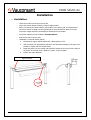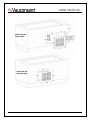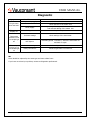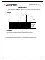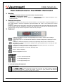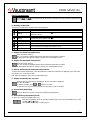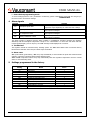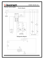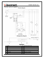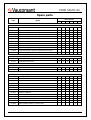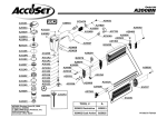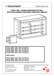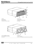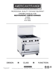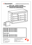
1
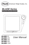
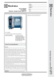
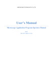
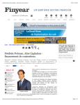
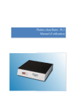
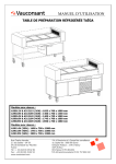
USER MANUAL
VISIO-LINE – REFRIGERATED WELL
STATIC COLD
Without glass cabinet:
A31908 (2GN): 820 x 700 x 70 mm
A31913 (3GN): 1150 x 700 x 70 mm
A31915 (4GN): 1475 x 700 x 70 mm
A31919 (5GN): 1800 x 700 x 70 mm
A31922 (6GN): 2150 x 700 x 70 mm
A31925 (7GN): 2450 x 700 x 70 mm
With glass cabinet:
With "Salad Bar" glass cabinet:
A31008 (2GN): 820 x 700 x 70+430 mm
A31013 (3GN): 1150 x 700 x 70+430 mm
A31015 (4GN): 1475 x 700 x 70+430 mm
A31019 (5GN): 1800 x 700 x 70+430 mm
A31022 (6GN): 2150 x 700 x 70+430 mm
A31025 (7GN): 2450 x 700 x 70+430 mm
A31108 (2GN): 820 x 700 x 70+530 mm
A31113 (3GN): 1150 x 700 x 70+530 mm
A31115 (4GN): 1475 x 700 x 70+530 mm
A31119 (5GN): 1800 x 700 x 70+530 mm
A31122 (6GN): 2150 x 700 x 70+530 mm
A31125 (7GN): 2450 x 700 x 70+530 mm
Rue Charles Hermite
Z.I des Sables – BP 59
54110 Dombasle-sur-Meurthe
France
Tel.: + 33 (0)3 83 45 82 82
Fax: +33 (0)3 83 45 82 93
www.vauconsant.com
Limited company with executive board and supervisory board
capitalised at €1,000,000
Postal cheques: 2145 J Nancy
NAF 28.93.Z
RCS Nancy B 757.804.042
Intracommunity VAT n° FR 52 757 804 042
USER MANUAL
Manual to be read and kept
Contents
Introduction ……………………………………………………………………..
3
Installation ……………………………………………………………………….
4
Commissioning / Use …………………………………………………………
8
Cleaning ………………..…………………………………………………………
9
Diagnostic ……………………………………………………………………….. 10
Maintenance ……………………………………………………………………. 11
Thermostat instructions / settings ......................................... 12
Electric and refrigeration diagrams …………………………….......... 15
Spare parts ……………………………………………………………………… 17
Technical support / Warranty …………………………..……………….. 18
Vauconsant SA, all rights reserved A310xx & A311xx & A319xx -rev0-FR, 18th November 2009
-2-
USER MANUAL
Introduction
Performance of the unit
The "cold static" refrigerated well is designed to keep food at a temperature lower than 8°C at core in a
room temperature of 25°C for a maximum of 60 minutes.
The temperature of the food provided should be between 0°C and 3°C.
These units comply with applicable EC norms and should be installed and used following the
instructions in this manual to ensure good performance and to be covered by the warranty.
Vauconsant SA, all rights reserved A310xx & A311xx & A319xx -rev0-FR, 18th November 2009
-3-
USER MANUAL
Installation
• Installation:
o
Insert the module into the purpose-cut slot.
o
Mount the switch cabinet vertically, using its angle bracket.
o
Before connecting the switch cabinet (fuse holder) to the power grid, it is imperative to
control its tension to adapt it to that mentioned on the manufacturer' plate of the unit.
The mains supply should be protected by a differential circuit breaker.
o
The switch cabinet must be located in closed premises.
o
Seal the top with a silicone joint.
o
Installation of a breath shield (option)
1.
Dismantle the upper glass brackets with a Allen spanner Ø 2.5
2.
Stick the black non-slip adhesive patches in the specified markings on the part of the
bracket in contact with the breath shield.
3.
Install the glass, the non-domed end should be positioned 120 mm from the edge of
the beam. In the case of the "salad bar" option, centre the glass.
4.
Tighten the upper brackets.
Upper brackets
Vauconsant SA, all rights reserved A310xx & A311xx & A319xx -rev0-FR, 18th November 2009
-4-
USER MANUAL
View from the
service side
View from the
customer side
Vauconsant SA, all rights reserved A310xx & A311xx & A319xx -rev0-FR, 18th November 2009
-5-
USER MANUAL
Refrigeration connection
Installation of the condensation generator
The condensation generator should be positioned facing the ventilation grid provided which is the
same format as the condenser.
It is imperative to position the condenser as close as possible (1 cm) to the ventilation grid.
1 cm
Connect the refrigerating circuit, following the refrigeration diagram.
•
Option with condensation generator supplied
Tightening of connections with protective cap
1.
2.
3.
4.
5.
Manually tighten both ½ female and male connections with protective cap
Use two flat 27/33 spanners to strike the ½ protective caps
Continue to tighten to obtain the tightness (2 cycles of tightening force )
Test tightness with soapy water or a leak detector
Repeat the operation with both ¼ female and male connections with protective cap
(identified with red tape) using 21/19 flat spanners.
Before tightening
After tightening
Vauconsant SA, all rights reserved A310xx & A311xx & A319xx -rev0-FR, 18th November 2009
-6-
USER MANUAL
Connect the pluggable connectors
Evaporation tank option
o
The tank should be preferably positioned in front of the generator to facilitate exit of
condensate vapours and avoid hot air intake.
o
The evaporation tank's supply cable should be connected to the socket installed in the switch
box of the unit.
o
Thedeflecting sheet placed in the evaporation tank is used to guide the steam. It should be
positioned at the centre of the evaporation tank (or should have the same play each side of the
sheet) and should follow the incline direction, as shown on the diagrams below.
deflector
o
Mount the draining tube on the plug, not forgetting the joint supplied. Place the tube at the
other end in the clip provided on the evaporation tank.
NB: The evaporation tray is only designed to evacuate defrosted water.
Installation of the ventilated evaporation tray
If the generator is at a distance, the tray should be placed in front of a grid to facilitate output of
condensate vapours.
•
The condensation generator option is not supplied
The connection should be done by a professional refrigeration technician.
Vauconsant SA, all rights reserved A310xx & A311xx & A319xx -rev0-FR, 18th November 2009
-7-
USER MANUAL
Commissioning / Use
• Commissioning:
Switch the well on two hours before filling it.
• Use:
Well
Press the
thermostat button.
Once the thermostat is on, the generator starts a minute afterwards (safety delay-time) to supply
the glass cabinet.
The thermostat is set in the factory after tests.
When the temperature required is reached, the generator stops automatically.
Press the
thermostat button to stop regulation of the unit.
Lighting option
Press the
thermostat button to switch lighting on and off.
Setting of the thermostat
See section "User instructions for the XW40L thermostat"
Automatic defrosting
This function set in the factory is built into the thermostat.
See section "User instructions for the XW40L thermostat"
Vauconsant SA, all rights reserved A310xx & A311xx & A319xx -rev0-FR, 18th November 2009
-8-
USER MANUAL
Cleaning
Always take care to switch off the appliance with thermostat before cleaning. This unit is not
impermeable to water. Do not use a high pressure water jet to clean it inside or out.
Every day:
•
Metal surfaces:
Stainless steel should be cleaned with soapy warm water or a special product for high quality
metal surfaces. Never use abrasive sponges or scourers to avoid scratching the surface.
•
Glass (breath shield):
Clean using a high quality glass cleaning product and clean cloth. Never use abrasive sponges or
scourers to avoid scratching the surface.
Vauconsant SA, all rights reserved A310xx & A311xx & A319xx -rev0-FR, 18th November 2009
-9-
USER MANUAL
Diagnostic
Symptoms
Possible causes
No electricity supply
The generator
does not start
Thermostat off
Faulty supply
Thermostat
displays P1
Remedies
Switch on the thermostat
Check the general circuit breaker
Check the fuse in the switch box
Check tightening of the lugs and wires on all the internal
and external cabling of the switch box
Faulty probe
Replace the probe
Thermostat
switched on No
Cold COMP light
off
Incorrect settings
Check settings of the thermostat.
DEF light on
Defrosting period. To delete it, switch the thermostat off
and back on again.
Thermostat
switched off No
Cold COMP light
on
Incorrect settings
Check settings of the thermostat.
Faulty connections
Check the generator's connections
NB
Fuses should be replaced by the same type and same caliber fuses.
If you have not solved your problem, contact a refrigeration professional.
Vauconsant SA, all rights reserved A310xx & A311xx & A319xx -rev0-FR, 18th November 2009
- 10 -
USER MANUAL
Maintenance
Always remember to switch off the appliance by opening the fuse holder before any
maintenance operations.
•
Features:
Reference
A31908
A31913
A31915
A31919
A31922
A31925
With glass cabinet
A31008 & A31108
A31013 & A31113
A31015 & A31115
A31019 & A31119
A31022 & A31122
A31025 & A31125
•
Capacity
2GN
3GN
4GN
5GN
6GN
7GN
2GN
3GN
4GN
5GN
6GN
7GN
Power
Refrigeration
Electric
272 W
300 W
272 W
300 W
272 W
300 W
272 W
300 W
272 W
300 W
272 W
300 W
272 W
272 W
272 W
272 W
272 W
272 W
400 W
400 W
400 W
400 W
400 W
400 W
Option
evaporation
tray
+ 600 W
Option
evaporation
tray
+ 600 W
Procedures:
Every 4 months, check that the condenser is not blocked and clean it properly.
Every year, check that the condenser's ventilator works properly.
The installer should check electric connections when commissioning the unit then once a year.
Any other maintenance operation should be done by a professional.
Vauconsant SA, all rights reserved A310xx & A311xx & A319xx -rev0-FR, 18th November 2009
- 11 -
USER MANUAL
User instructions for the XW40L thermostat
1. Warning
o Important: disconnect electrical connections before any intervention.
o The appliance should not be opened.
o In the event of a breakdown, send the appliance to
, with a detailed description of the
problem observed.
2. General description
The XW 40L is a regulator with microprocessor aimed at medium or low temperature refrigeration applications. It
has 3 relay outputs to control the compressor, light and ventilator and 1 NTC or PTC probe input to control
temperature.
Regulation is obtained by the temperature measured by an atmospheric probe with positive differential with respect
to the set point: when the temperature increases and reaches the set point plus the differential, then the
compressor starts. It stops when the temperature reaches the set point again.
3. Keyboard
CF
V
To display and modify the set point. In programming mode, this key is used to select a setting or
confirm an operation.
By pressing this key for 3 seconds when the maximum or minimum temperature is displayed, it will be
erased.
To display the maximum temperature recorded. In programming mode, this key is used to browse
through the list of settings or increase the displayed value. By pressing this key for 3 seconds, the rapid
refrigeration cycle starts.
To display the minimum temperature recorded. In programming mode, this key is used to browse
through the list of settings or reduce the displayed value.
By keeping it pressed down for 3 seconds, defrosting starts.
Starts or switches off lighting
Switches the appliance on or off.
COMBINED KEYS
+
+
+
To lock or unlock the keyboard.
To enter programming mode.
To leave programming mode.
a. Lock and unlock the keyboard
LOCK THE KEYBOARD
Press the
and
keys at the same time for more than 3 seconds. The "POF" message is displayed
and the keyboard is locked. It is then only possible to see the set point, minimum and maximum
temperatures and activate or disactivate the lights and regulator.
Vauconsant SA, all rights reserved A310xx & A311xx & A319xx -rev0-FR, 18th November 2009
- 12 -
USER MANUAL
UNLOCK THE KEYBOARD
Press the
and
keys simultaneously for more than 3 seconds. The "POn" message is displayed and
the keyboard is unlocked.
b. Meaning of the LEDs
The function of each LED is described in the following table:
LED
MODE
ON
Compressor on.
Programming phase (flashes with
Flashing
Anti-short cycle on
ON
Ventilator on
Flashing
Programming phase (flashes with
ON
Flashing
ON
ON
ON
FUNCTION
)
)
Defrosting on
Drainage in progress
Rapid refrigeration cycle on
Signals an alarm
In "Pr2" indicates the settings also present in "Pr1"
The light is on
c. Display the minimum temperature
Press and release this key.
The "Lo" message is displayed followed by the minimum temperature recorded.
By pressing this key again or waiting 5 seconds, the normal display returns.
d. Display the maximum temperature
Press and release this key.
The "Hi" message is displayed followed by the maximum temperature recorded.
By pressing this key again or waiting 5 seconds, the normal display returns.
e. Reboot minimum and maximum temperatures
To reboot the recorded temperature, when the maximum or minimum temperature is displayed, press on the SET
key until the "rST" code starts to flash.
N.B.: After an installation, reboot the recorded temperature.
f. Display and modify the set point
Press the SET key and release it immediately: the set point value is displayed.
The SET LED flashes.
To change the value, press
or
within 10 seconds.
To store the new set point value, press the SET key again or wait 10 seconds.
g. Start manual defrosting
Press the DEF key more than 2 seconds and manual defrosting starts.
h. Enter the Pr1 programming mode
To enter "Pr1" (settings accessible to the user):
Enter the programming mode by pressing simultaneously on the SET and DOWN keys for a few
seconds (
and
flash).
The regulator displays the 1st setting in "Pr1".
Vauconsant SA, all rights reserved A310xx & A311xx & A319xx -rev0-FR, 18th November 2009
- 13 -
USER MANUAL
i. Enter the Pr2 programming mode
To access settings present in "Pr2" (accessible to technicians), please contact
the secret code to access these settings.
, who will give you
4. Alarm signals
Message
Cause
"P1"
Atmospheric probe fault
"HA"
High temperature alarm
"LA"
Low temperature alarm
"EE"
Memory breakdown or fault
Outputs
ON alarm output
Compressor output depending on "COn" and "COF" settings
ON alarm output
Other outputs unchanged
ON alarm output
Other outputs unchanged
ON alarm output
Other outputs unchanged
The alarm message is displayed until the alarm condition is reestablished. All alarm messages are displayed
alternately with the atmospheric temperature except for "P1" which flashes. To reboot the "EE" alarm and start
normal operation again, press on any key. The "rSt" message will be displayed for 3 seconds.
a. The EE alarm
The regulator includes an internal memory checking system. The "EE" alarm flashes when an internal memory
fault has been detected. In this case, the alarm output is activated.
b. Alarm reset
"P1" probe alarms (probe defect), "P2": they stop automatically 10 seconds after the probe has resumed normal
operation. Check the connections before putting back the probe.
"HA" and"LA" temperature alarms: they stop automatically when the regulator's temperature returns to normal
values or when defrosting starts.
5. Settings programmed in the factory
Setting
Set
Hy
AC
rES
IdF
MdF
ALU
ALL
ot
Adr
P2r
Name
Set point
Differential
Anti-short cycle time
Resolution
Interval between defrosting cycles
(Maximum) defrosting time
High temperature alarm
Minimum temperature alarm
Atmospheric probe calibration
Serial address (not used)
Access to the list of protected settings (read only)
Value
-8
1
1
dE
7
0
8
2
0
1
Vauconsant SA, all rights reserved A310xx & A311xx & A319xx -rev0-FR, 18th November 2009
- 14 -
USER MANUAL
Generator option supplied
Electric diagram
Refrigeration diagram
Vauconsant SA, all rights reserved A310xx & A311xx & A319xx -rev0-FR, 18th November 2009
- 15 -
USER MANUAL
Generator option not supplied
Electric diagram
Refrigeration diagram
Caption
B
C
Ca
Cd
D
Dh
Kb
Kd
Q
Rb
Ballast
Compressor
Capillary
Condenser
Reducing valve
Dehydrator
Evaporation tray contactor
Defrosting contactor
Fuse holder
Evaporation tray heating element
Rd
S
Sf
Sn
St
T
Tb
Tf
Va
Vc
Defrosting heating element
Coil
Starter
Evaporation well water level probe
Temperature probe
XW40L thermostat
Evaporation tray safety thermostat
Fluorescent tube
Schraeder ¼ connection
Condenser ventilator
Vauconsant SA, all rights reserved A310xx & A311xx & A319xx -rev0-FR, 18th November 2009
- 16 -
USER MANUAL
Spare parts
Code
Name
Unit capacity
2GN 3GN 4GN 5GN 6GN 7GN
Accessories
03.0742
Upper domed glass, 647 mm long
03.0743
Upper domed glass, 992mm long
03.0750
Upper domed glass, 1,297mm long
03.0755
Upper domed glass, 1,647mm long
03.0760
Upper domed glass, 1,997mm long
03.0765
Upper domed glass, 2,297mm long
03.0787
Upper domed glass, 647 mm long domed on two sides
03.0788
Upper domed glass, 992mm long domed on two sides
03.0795
Upper domed glass, 1,297mm long domed on two sides
03.0800
Upper domed glass, 1,647mm long domed on two sides
03.0802
Upper domed glass, 1,997mm long domed on two sides
03.0805
Upper domed glass, 2,297mm long domed on two sides
X
X
X
X
X
X
X
X
X
X
X
X
Electric equipment
06.0038
600W evaporation tray element
X
X
X
X
X
X
12.0273
Dixell XW40L thermostat
X
X
X
X
X
X
X
X
X
X
X
X
Compressor generator
12.2750
AEZ 4425 ZH condensation generator
12.2752
AEZ 3430 ZH condensation generator
Fluorescent tube lighting
06.4778
438mm 15W power fluorescent tube
06.4780
590mm 18W power fluorescent tube
06.4784
970mm 36W power fluorescent tube
06.4786
1,200mm 36W power fluorescent tube
06.4788
1,500mm 58W power fluorescent tube
06.4810
Ballast for 18 W tube
06.4812
Ballast for 36W tube
06.4813
Ballast for 58W tube
06.4828_A
Water resistant sheath for 440 mm tube
06.4820
Water resistant sheath for 590mm tube
06.4828_B
Water resistant sheath for 970mm tube
06.4822
Water resistant sheath for 1,200mm tube
06.4826
Water resistant sheath for 1,500mm tube
X
X
X
X
X
X
X
X
X
X
X
X
X
X
X
Vauconsant SA, all rights reserved A310xx & A311xx & A319xx -rev0-FR, 18th November 2009
X
X
X
- 17 -
USER MANUAL
Technical support
[email protected]
Spare Parts Department: +33 (0)3 83 45 82 78
Hotline:
+33 (0)3 83 45 44 48
Fax:
+33 (0)3 83 45 82 75
Warranty
The appliance's warranty applies as of the shipment date from our factory in Dombasle Sur Meurthe
(France) for a period of 12 months. It does not cover breakage of the glass.
To benefit from the warranty, the buyer should order by fax or email, specifying the warranty
application with appliance reference found on the identification plaque. On reception of the appliance, the
buyer should return and pay shipment for the defective appliance, within fifteen working days. Any appliance
not returned shall be invoiced. Any appliance bought from another supplier may not benefit from a credit as
covered by the warranty.
Transport and labour costs are to be paid by the buyer.
The buyer is invited to make any reservations to customers for appliances stored without
commissioning on delivery, particularly for refrigerated and electrical equipment.
The warranty does not extend to wear caused by defects or poor maintenance of equipment or damage
caused by knocks or improper use.
Any warranty also excludes incidents caused by fortuitous events or force majeure, unidentified causes
or causes by the buyer's actions of any form whatsoever: improper location, faults linked to use (operation,
maintenance not in accordance with this manual, unqualified staff, etc.), modification of the equipment,
repair conducted outside the terms of this manual, spare parts, etc.
Liability
Vauconsant's liability is strictly limited to the obligations defined above and it is formally agreed that
Vauconsant shall not be required to pay compensation.
Under not circumstances shall Vauconsant be required to pay compensation for any immaterial or
indirect damage such as: loss of business, loss of profit, loss of an opportunity, commercial prejudice,
shortfall.
In any case, Vauconsant's civil liability, for all causes, with the exception of corporal damage and fraud
or serious misdemeanour, may not exceed the sum of the contract.
The buyer and its insurers shall not take legal action against Vauconsant and its insurance companies
above and beyond the limits and exclusions set out above.
Vauconsant SA, all rights reserved A310xx & A311xx & A319xx -rev0-FR, 18th November 2009
- 18 -