1
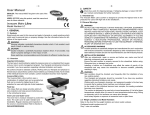
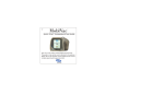
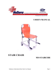
Transfer Bench Assembly, Installation and Operating Instructions Model Nos. 9670, 9670U, 9670C NOTE: Check ALL parts for shipping damage. If shipping damage is noted, DO NOT use. Contact Carrier/ Dealer for further instruction. MODEL 9670 9670U 9670C SPECIFIC WARNINGS CONTINUED After ANY adjustments, repair or service and BEFORE use, make sure all attaching hardware is securely tightened - otherwise injury or damage may result. DESCRIPTION Assembled w/o commode Unassembled w/o commode Assembled with commode Tools Required: Phillips Screwdriver; Crescent Wrench, Slotted Screwdriver SAFETY SUMMARY The following recommendations are made for the safe use of the Transfer Bench: NOTE: The illustrations in this instruction sheet reflect the Transfer Bench w/o commode. The transfer bench with commode assembles in the same manner. GENERAL WARNINGS DO NOT use this equipment without first reading and understanding this instruction sheet. If you are unable to understand the Warnings, Cautions, and Instructions, contact your Invacare dealer or Invacare Account Services at 1-800-333-6900 before attempting to use this equipment - otherwise, injury or damage may occur. ATTACHING THE TRANSFER BENCH LEGS (FIGURE 1) NOTE: Refer to SPECIFIC WARNINGS in the SAFETY SUMMARY of this instruction sheet. 1. Remove all components of the transfer bench and attaching hardware from the packaged container. SPECIFIC WARNINGS NOTE: If your transfer bench is assembled, proceed to ATTACHING THE SEAT ARM in this instruction sheet. The weight limitation of a transfer bench manufactured BEFORE November 1, 1999 is 350 lbs. (159kg.). The weight limitation of transfer bench Manufactured AFTER November 1, 1999 is 400 lbs. (181.4 kg.). The serial number (date code decal), located on the underside of the seat, is a 5 (five) digit identification and traceability label detailing the date of manufacture, arranged as follows: XXXXX 1st digit signifies the last digit of the year. XXXXX 2nd and 3rd digits signify the month. XXXXX 4th and 5th digits signify the day. Example: 91101 = November 1, 1999 2. Place seat upside down on floor/work bench. 3. Position transfer bench legs on the underside of the seat (snap buttons face inward). 4. Secure transfer bench legs to underside of seat with the eight (8) slotted mounting screws provided. Securely tighten. 5. Position the end rail against transfer bench legs, on the opposite side of the handle, and secure with the two (2) short phillips head mounting screws and locknuts provided. Securely tighten. Slotted Mounting Screws (Step 4) Users with limited physical capabilities should be supervised or assisted when using the transfer bench. Handle Transfer Bench Legs Ensure the compression buttons on the back are fully visible through notch on back of seat before using. Ensure leg extension snap buttons are fully engaged before use. Check rubber tips for rips, tears, cracks or wear. If any of these conditions exist, replace rubber tips immediately. Short Phillips Mounting Screws (Step 5) Seat Snap Buttons Most tub floors are higher than the bathroom floor. Before using, ensure that the two (2) legs inside the tub are adjusted to the same height and the two (2) legs outside the tub are adjusted to the same height, so that an level seat height adjustment is achieved. DO NOT use if wobbly or unstable. End Rail (Step 5) Slotted Mounting Screws (Step 4) FIGURE 1 - ATTACHING THE TRANSFER BENCH LEGS 1 ATTACHING THE SEAT ARM (FIGURE 2) Removing NOTE: Refer to SPECIFIC WARNINGS in the SAFETY SUMMARY of this instruction sheet. 2. Hold back handles and lift up. Back Handles Back 1. To remove back, place one (1) knee on the seat. 1. Place transfer bench in upright position. 2. To attach the seat arm to the transfer bench, perform the following: Slot BACK VIEW Slot Seat A. Locate the end rail beneath the soap dish. B. Remove the hardware that secures the end rail to the transfer bench. 3. Position the end rail against the transfer bench leg. Position seat arm on outside of transfer bench leg. Thread the two (2) long phillips head mounting screws through the seat arm, the transfer bench leg, and the end rail. Secure with the two (2) locknuts provided. Securely tighten. Notch Compression Buttons FIGURE 3 - INSTALLING/REMOVING THE BACK 4. Install the back. Refer to INSTALLING/REMOVING THE BACK in this instruction sheet. ADJUSTING LEG EXTENSIONS (FIGURE 3) 5. Adjust the leg extensions, if necessary. Refer to ADJUSTING THE LEG EXTENSIONS in this instruction sheet. NOTE: Refer to SPECIFIC WARNINGS in the SAFETY SUMMARY of this instruction sheet. 1. Select one (1) of the nine (9) adjustment holes located on the lower leg frame. 2. Depress the snap button and slide the leg extension up or down to the desired height until snap button protrudes fully through the adjustment hole of the leg extension. 3. Repeat for the other legs. 4. Make sure all four (4) legs are adjusted so that the transfer bench sits level in and outside the tub. Transfer Bench Soap Dish Seat Arm End Rail Locknut Adjustment Holes Transfer Bench Leg Long Phillips Head Mounting Screws Snap Button Leg Extension FIGURE 2 - ATTACHING THE SEAT ARM FIGURE 3 - ADJUSTING LEG EXTENSIONS INSTALLING/REMOVING THE BACK (FIGURE 3) CLEANING NOTE: Refer to SPECIFIC WARNINGS in the SAFETY SUMMARY of this instruction sheet. NOTE: BEFORE using any cleaning products, test an area on the underside of the seat for any discoloration or staining. Installing 1. Use a mild soap and water or non-abrasive cleanser to clean the Transfer Bench. 1. Position back in slots provided on seat. 2. Push down on back until back is secured. 3. Ensure the compression buttons on the back are fully visible through notch on back of seat before using. 2 MODEL NO. 9670/9670U MODEL NO. 9670C 1 1 2 2 6 3 6 12 12 5 5 3 16 13 16 13 4 4 9 7 9 7 10 10 11 15 11 14 8 8 QUANTITY ITEM 1. 2. 3. 4. 5. 6. 7. 8. 9. 10. 11. 12. 13. 14. 15. 16. DESCRIPTION SEAT BACK TRANSFER BENCH SEAT ARM 10-32 x1-1/2 PH HD SCREW BENCH LEG END RAIL RELEASE SPRING SNAP BUTTON ANTI-RATTLE LEG EXTENSIONS CRUTCH TIP 1/4-20 X 1-1/4 PH SCREW 1/4-20 LOCKNUT COMMODE, PAIL PAIL HOLDER 1/4-20 x 1-1/2 PH SCREW 9670/9670U 1 1 1 8 2 2 4 4 4 4 4 2 4 N/A N/A 2 3 9670C 1 1 1 8 2 2 4 4 4 4 4 2 4 1 2 2 LIMITED WARRANTY PLEASE NOTE: THE WARRANTY BELOW HAS BEEN DRAFTED TO COMPLY WITH FEDERAL LAW APPLICABLE TO PRODUCTS MANUFACTURED AFTER JULY 4, 1975. This warranty is extended only to the original purchaser/user of our products. This warranty gives you specific legal rights and you may also have other legal rights which vary from state to state. Invacare warrants the Transfer Bench to be free from defects in materials and workmanship for the lifetime of the product for the original purchaser/user. If within such warranty period any such product shall be proven to be defective, such product shall be repaired or replaced, at Invacare’s option. This warranty does not include any labor or shipping charges incurred in replacement part installation or repair of any such product. Invacare’s sole obligation and your exclusive remedy under this warranty shall be limited to such repair and/or replacement. For warranty service, please contact the dealer from whom you purchased your Invacare product. In the event you do not receive satisfactory warranty service, please write directly to Invacare at the address below, provide dealers name, address, date of purchase, indicate nature of the defect and, if the product is serialized, indicate the serial number. Do not return products to our factory without our prior consent. LIMITATIONS AND EXCLUSIONS: THE FOREGOING WARRANTY SHALL NOT APPLY TO SERIAL NUMBERED PRODUCTS IF THE SERIAL NUMBER HAS BEEN REMOVED OR DEFACED; PRODUCTS SUBJECTED TO NEGLIGENCE, ACCIDENT, IMPROPER OPERATION, MAINTENANCE OR STORAGE, COMMERCIAL OR INSTITUTIONAL USE; PRODUCTS MODIFIED WITHOUT INVACARE’S EXPRESS WRITTEN CONSENT INCLUDING, BUT NOT LIMITED TO, MODIFICATION THROUGH THE USE OF UNAUTHORIZED PARTS OR ATTACHMENTS; PRODUCTS DAMAGED BY REASON OF REPAIRS MADE TO ANY COMPONENT WITHOUT THE SPECIFIC CONSENT OF INVACARE; OR TO A PRODUCT DAMAGED BY CIRCUMSTANCES BEYOND INVACARE’S CONTROL. SUCH EVALUATION WILL BE SOLELY DETERMINED BY INVACARE. THE WARRANTY SHALL NOT APPLY TO PROBLEMS ARISING FROM NORMAL WEAR OR FAILURE TO ADHERE TO THE THESE INSTRUCTIONS. THE FOREGOING WARRANTY IS EXCLUSIVE AND IN LIEU OF ALL OTHER EXPRESS WARRANTIES. IMPLIED WARRANTIES, IF ANY, INCLUDING THE IMPLIED WARRANTIES OF MERCHANTABILITY AND FITNESS FOR A PARTICULAR PURPOSE, SHALL NOT EXTEND BEYOND THE DURATION OF THE EXPRESS WARRANTY PROVIDED HEREIN AND THE REMEDY FOR VIOLATIONS OF ANY IMPLIED WARRANTY SHALL BE LIMITED TO REPAIR OR REPLACEMENT OF THE DEFECTIVE PRODUCT PURSUANT TO THE TERMS CONTAINED HEREIN. INVACARE SHALL NOT BE LIABLE FOR ANY CONSEQUENTIAL OR INCIDENTAL DAMAGES WHATSOEVER. SOME STATES DO NOT ALLOW THE EXCLUSION OR LIMITATION OF INCIDENTAL OR CONSEQUENTIAL DAMAGE, OR LIMITATION ON HOW LONG AN IMPLIED WARRANTY LASTS, SO THE ABOVE EXCLUSIONS AND LIMITATIONS MAY NOT APPLY TO YOU. THIS WARRANTY SHALL BE EXTENDED TO COMPLY WITH STATE/PROVINCIAL LAWS AND REQUIREMENTS. Invacare Corporation USA One Invacare Way Elyria, Ohio USA 44036-2125 800-333-6900 www.invacare.com Invacare and Yes, you can. are trademarks of Invacare Corporation. © 2000 Invacare Corporation Form No. 96-161 Part No. 1064531 Rev C (1) 12/00